EP2398540B1 - Steerable catheter having intermediate stiffness transition zone - Google Patents
Steerable catheter having intermediate stiffness transition zone Download PDFInfo
- Publication number
- EP2398540B1 EP2398540B1 EP10705508.9A EP10705508A EP2398540B1 EP 2398540 B1 EP2398540 B1 EP 2398540B1 EP 10705508 A EP10705508 A EP 10705508A EP 2398540 B1 EP2398540 B1 EP 2398540B1
- Authority
- EP
- European Patent Office
- Prior art keywords
- section
- stiffness
- catheter
- zone
- shaft
- Prior art date
- Legal status (The legal status is an assumption and is not a legal conclusion. Google has not performed a legal analysis and makes no representation as to the accuracy of the status listed.)
- Active
Links
- VONKRKBGTZDZNV-UHFFFAOYSA-N CC=C1CCCC1 Chemical compound CC=C1CCCC1 VONKRKBGTZDZNV-UHFFFAOYSA-N 0.000 description 1
Images


Classifications
-
- A—HUMAN NECESSITIES
- A61—MEDICAL OR VETERINARY SCIENCE; HYGIENE
- A61M—DEVICES FOR INTRODUCING MEDIA INTO, OR ONTO, THE BODY; DEVICES FOR TRANSDUCING BODY MEDIA OR FOR TAKING MEDIA FROM THE BODY; DEVICES FOR PRODUCING OR ENDING SLEEP OR STUPOR
- A61M25/00—Catheters; Hollow probes
- A61M25/01—Introducing, guiding, advancing, emplacing or holding catheters
- A61M25/0105—Steering means as part of the catheter or advancing means; Markers for positioning
- A61M25/0133—Tip steering devices
- A61M25/0141—Tip steering devices having flexible regions as a result of using materials with different mechanical properties
-
- A—HUMAN NECESSITIES
- A61—MEDICAL OR VETERINARY SCIENCE; HYGIENE
- A61M—DEVICES FOR INTRODUCING MEDIA INTO, OR ONTO, THE BODY; DEVICES FOR TRANSDUCING BODY MEDIA OR FOR TAKING MEDIA FROM THE BODY; DEVICES FOR PRODUCING OR ENDING SLEEP OR STUPOR
- A61M25/00—Catheters; Hollow probes
- A61M25/01—Introducing, guiding, advancing, emplacing or holding catheters
- A61M25/0105—Steering means as part of the catheter or advancing means; Markers for positioning
- A61M25/0133—Tip steering devices
- A61M25/0144—Tip steering devices having flexible regions as a result of inner reinforcement means, e.g. struts or rods
-
- A—HUMAN NECESSITIES
- A61—MEDICAL OR VETERINARY SCIENCE; HYGIENE
- A61M—DEVICES FOR INTRODUCING MEDIA INTO, OR ONTO, THE BODY; DEVICES FOR TRANSDUCING BODY MEDIA OR FOR TAKING MEDIA FROM THE BODY; DEVICES FOR PRODUCING OR ENDING SLEEP OR STUPOR
- A61M25/00—Catheters; Hollow probes
- A61M25/01—Introducing, guiding, advancing, emplacing or holding catheters
- A61M25/0105—Steering means as part of the catheter or advancing means; Markers for positioning
- A61M25/0133—Tip steering devices
- A61M25/0147—Tip steering devices with movable mechanical means, e.g. pull wires
Definitions
- This invention relates to steerable intra-vascular catheters, such as endovascular electrophysiology mapping and ablation catheters.
- Electrophysiology is the study of electrical impulses that are transmitted through the heart and is focused primarily on diagnosing and treating arrhythmias, or conditions in which electrical impulses within the heart vary from the normal rate or rhythm of a heartbeat.
- a common arrhythmia is atrial fibrillation (AF), which is characterized by rapid, disorganized contractions of the heart's upper chambers, the atria. AF results from abnormal electrical impulses propagating through aberrant myocardial tissue pathways, which leads to ineffective pumping of the blood through the heart, as well as other complications.
- AF atrial fibrillation
- Atria flutter (AFL) another type of arrhythmia, is characterized by a rapid beating of the atria.
- AFL arises from a single electrical wave that circulates rapidly throughout the right side of the heart. Since this arrhythmia can arise from multiple electrical sites, effective treatment of these conditions requires electrical isolation of the aberrant signal sites, thereby forcing the heart's normal conduction pathway to take over.
- the practice of interventional electrophysiology for treating arrhythmias generally involves inserting catheters into a patient's vasculature (e.g., through the groin and inferior vena cava) and navigating the distal or "working" end of the catheters into the patient's heart chambers to identify or "map" the locations of heart tissue that are a source of the arrhythmias.
- the mapping of the heart's electrical activity is typically accomplished using one or more pairs of electrodes that are axially spaced apart from each other along the working end of the catheter.
- the attending physician may use a separate ablation catheter or ablation electrode carried by the catheter that is also used for mapping to disable (or “ablate") the tissue containing the aberrant signal(s) or signal pathway(s), thereby restoring the heart to its normal rhythm.
- mapping electrodes in surface area
- lead wires that connect mapping electrodes to processing circuitry are much smaller than are used to couple ablation electrodes to an RF generator.
- a larger number of electrodes may be provided on a mapping catheter than on an ablation catheter having a same or similar profile.
- WO 2006/091597 A1 discusses a deflectable sheath catheter comprising different flexible segments which have different stiffness.
- WO 96/40347 discusses a catheter the shaft of which may have continuously graduated stiffness from a proximal to a distal end of the shaft.
- US 2002/0177840 A1 discusses a medical device shaft including a plurality of slits of varying frequency, location and depth, which can be used for varying the stiffness of the shaft.
- US patient number 5,928,191 discusses a catheter including an elongate body the stiffness of which may be adapted by moving a stiffness increasing member along the length of the elongate body.
- Embodiments include steerable catheters, as described in claim 1 having a heterogeneous, multi-zone stiffness profile such that a catheter shaft has smooth or gradual transitions between different stiffnesses of distal and proximal portions of the shaft, thereby providing for improved distal torque transmission (ability of the steerable distal portion to transmit input rotational force from the handle to a distal tip), trackability (ability of the entire catheter to follow itself through varying and tortuous anatomy), pushability (ability of the catheter to efficiently move axially through the anatomy), lateral stability (ability of a distal tip electrode to remain stable on the heart tissue when subjected to side loading) and distal durability (ability of the steerable distal portion to remain undamaged when subjected to clinical use).
- the shaft is structured such that catheter pushability and torque transmission are maximized, while the most distal portion is structured to emphasize stiffness transition and lateral stability.
- a steerable intravascular catheter comprises an elongate flexible shaft or tube having a proximal portion and a steerable distal portion and that includes a first, distal section, a second, transition section that is proximal relative to, and less flexible than, the first section, and a third section that is proximal relative to, and less flexible than, the first and second sections.
- the flexibility or stiffness of the second section varies along its length to gradually transition between the first and third sections.
- the steering apparatus can be integrated into various shafts of various catheters.
- a steerable intravascular catheter comprises an elongate flexible shaft or tube having a proximal portion and a steerable distal portion.
- the shaft includes a first, distal section, a second, transition section that is proximal relative to, and stiffer or less flexible than, the first section, and a third section that is proximal relative to, and stiffer or less flexible than, the first and second sections, and a fourth section that is proximal relative to the third section and stiffer or less flexible than the first, second and third sections.
- the flexibility or stiffness of the first section is substantially constant along its length, and the flexibility or stiffness of the second section varies along its length to gradually transition between the first section and the third section.
- the steering apparatus can be incorporated into a shaft of various catheters.
- a steerable intravascular catheter comprises an elongate, flexible shaft, a steering apparatus and an electrode.
- the shaft has a proximal portion, which may extend from a handle, and a steerable distal portion.
- the electrode is carried on the steerable distal portion of the shaft.
- the steering apparatus is positioned within the shaft and includes a first, distal section, a second, transition section that is proximal relative to and stiffer or less flexible than, the first section, and a third section that is proximal relative to, and stiffer or less flexible than, the first section.
- the flexibility or stiffness of the second section varies along its length to transition between the first and third sections.
- the catheter shaft may also include one or more control elements or wires that can be manipulated to move the steering apparatus and catheter shaft in different directions.
- the stiffness of the catheter shaft is varied along the length to provide a gradual transition by incorporating various stiffness zones directly into an outer tubing of the catheter shaft or body.
- tubing segments of various stiffnesses may be stacked on a common inner core and thermally fused into a single shaft.
- the resulting shaft has at least two distinct stiffness zones and a "transition zone” or "step-like” or “ramp-like” transition between the two stiffness zones.
- extrusion technologies such as interrupted co-extrusion may be used that directly integrate materials of different stiffnesses into a single tube over a common lumen.
- the resulting tube will have at least two distinct stiffness zones and a transition zone between the two stiffness zones.
- a gradual transition between two adjacent stiffness zones of a distal portion of a shaft is may be substantially linear, e.g., as a step-like or ramp-like transition or slope between two stiffness levels.
- the gradual transition may also be non-linear, e.g., parabolic or exponential.
- the first or distal section may also transmit less torque than the second section, which may transmit less torque than the third section.
- a catheter may include one or more additional sections.
- a fourth section may be proximal relative to the third section and stiffer or less flexible than each of the more distal sections.
- the fourth section may have a substantially constant or distinct stiffness or flexibility.
- At least one other section of a catheter steering apparatus other than an intermediate or second section includes a variable flexibility or stiffness along at least a portion of its length.
- the flexibility or stiffness of at least a portion of the third section can vary along its length.
- the third section may include multiple segments. A first segment of the third section is proximal relative to and adjacent to the second section. A second segment of the third section is proximal relative to and adjacent to the first segment of the third section and is stiffer or less flexible than the first segment of the third section.
- the first or distal section of the steering apparatus has a substantially constant or distinct flexibility or stiffness along its length, and the flexibility or stiffness of the second segment of the third section also varies along its length. The rate at which the stiffness or flexibility changes in the second section is more gradual than the rate which stiffness or flexibility changes in the second segment of the third section.
- the first or distal section of a catheter shaft includes a substantially constant or distinct flexibility or stiffness along its length. At least a portion of the third section is stiffer than the first section and has a substantially constant or distinct flexibility or stiffness.
- the first or distal section of a catheter shaft includes an internal support member, which may be formed from or made of a material that has a yield strength greater than about 120,000 pounds per square inch (827370 kPa) In one example the internal support member has a yield strength of about 140,000 psi (965266 kPa) and may be Type 301 stainless steel.
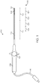
- a bi-directional steerable catheter 100 constructed according to certain embodiments includes an elongate, flexible shaft 110 that is structurally configured to have a heterogeneous, multi-zone stiffness profile or structure 120 having different or variable rigidity, stiffness or flexibility along its length.
- this specification generally refers to a multi-zone structure or profile 120 having different stiffness attributes, noting that sections having different stiffnesses have different flexibilities.
- the shaft 110 extends from a distal portion of a handle 130, as is known in the art of electrophysiology catheters.
- the catheter shaft 110 generally includes a proximal section or portion 111 and a steerable distal section or portion 112 that is sized and configured for placement and manipulation within in a heart of patient without prolapsing.
- Fig. 1 generally illustrates proximal and distal portions 111, 112, but the lengths of these portions 111, 112 and the dividing line between these portions 111, 112 may vary in different implementations and catheter designs.
- An electrical cable or other suitable connector 140 extending from a proximal end of the handle 130 may be coupled to a source of energy or other equipment (not shown in Fig. 1 ) for transmitting one or more ablation signals and/or receiving signals or data from mapping electrodes.
- Fig. 1 generally illustrates electrodes as a distal tip electrode 141 and shaft or ring electrodes 142.
- the catheter shaft 110 is advanced into a patient, e.g., through a puncture into the femoral vein of a patient, through the inferior vena cava and into the right atrium using a bi-directional steering support member 610 (shown in Fig. 6A ) that is embedded in the distal portion 112.
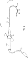
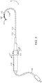
- An actuator 131 such as a rotatable knob or dial as shown in Fig. 2 , can be manipulated by the surgeon to position the distal section 112 of the shaft 110 as desired by adjusting tension on the steering member, e.g., forming the distal section 112 into a three-quarter loop in different directions as shown in Figs. 2-3 .
- an electrical current can be applied to one or more electrodes through the connector or cable 140 to map and/or ablate target tissue.
- non-ablative energy can be applied to target tissue through one or more mapping electrodes 142
- ablation energy can be applied to target tissue through a distal tip ablation electrode 141.
- Figs. 1-3 illustrate one manner in which electrodes 141, 142 may be configured, other electrode configurations may be utilized.
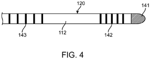
- Fig. 4 shows ring electrodes 142, 143, and an ablation tip electrode 141.
- various electrode configurations may also be utilized, and the electrodes may be used for ablation and/or mapping.
- the shaft 110 includes, or is formed or designed to have, a heterogeneous, multi-zone structure or profile 120 that includes different stiffness zones.
- the example of a stiffness profile illustrated in Fig. 5A includes four different stiffness zones 121-124, but other examples may include different numbers of stiffness zones, e.g., three, five or other numbers of stiffness zones.
- zones 121 and 122 form a distal section 112 of the shaft, and zones 123 and 124 form a proximal portion 111 of the shaft 110.
- At least one stiffness zone e.g., zone 122 of the distal portion 111 in the illustrated embodiment, is an intermediate stiffness zone that is configured to provide a smooth, gradual transition, step or ramp between two other zones 121 and 123 having different stiffness attributes.
- Different zones 121-124 may have different stiffness attributes as a result of having different stiffness magnitudes, i.e., one zone is stiffer or more flexible than another, different stiffness profiles or patterns, i.e., a zone may have a constant or substantially constant (i.e., distinct) stiffness, a variable stiffness, or both.
- Different zones of the multi-zone structure 120 can be formed or fabricated in different ways.
- the stiffness of the catheter shaft 110 is varied along the length by incorporating various stiffness zones directly into an outer tubing of the catheter shaft 110 or body. For example, sections of tubing with varying stiffness may be stacked on a common inner core and thermally fused into a single shaft 110.
- the resulting shaft 110 has at least two distinct stiffness zones and one transition zone there between.
- extrusion technologies such as interrupted co-extrusion may be used to directly integrate varying stiffness materials into a single tube over a common lumen.
- the resulting tube(s) will have at least two distinct stiffness zones and at least one intermediate transition zone between two stiffness zones.
- Each of the zones 121-124 can be same length or different lengths.
- a multi-zone structure 120 can be constructed in other ways, e.g., by selection and configuration of certain internal materials and components, and that these configurations and methods of fabrication are provided as examples of how examples may be implemented to provide for more gradual transitions between different sections of the catheter shaft 110, thereby providing improved pushability, tracking, and torsional strength and a smoother transition of flexibility along the length of the shaft 110 to optimize each section of the shaft 110.
- this specification refers to different materials and material configurations that can be used to implement a particular zone, but it should be understood that a multi-zone structure 120, including the multi-zone structure 120 illustrated in Fig. 5A , can be implemented in other ways.
- the catheter shaft 110 is structured to include four different stiffness zones 121-124.
- Fig. 5B illustrates stiffness in terms of lb f -in 2 , how bending stiffness varies across a length of a catheter shaft 110 constructed according to one embodiment, and how the bending stiffness of the intermediate or transition portion 122 varies according to embodiments.
- the bending stiffness 510 increases across four zones 121-124 from the distal portion 112 (left edge of the graph shown in Fig. 5 ) to the proximal portion 111 (right edge of the graph shown in Fig. 5B ) of the catheter shaft 110.
- a catheter shaft 110 can have a length of about 35-45 inches (88.9-114.3 cm) and the first or distal zone 121 of the distal portion 111 of the shaft 110 can have a length of about 1.5 inches (3.81 cm) to about 4.5 inches (114.3 cm) e.g., about 2.5 inches (6.35 cm) a diameter of about 0.092 inches (0.023cm) (and other suitable diameters), and be made of or include a polyether-polyamide block copolymer and Type 301 stainless steel (and other suitable materials).
- the second zone 122 of the distal portion 111 of the shaft 110 can have a length of about 1.0 inch (2.54 cm) to about 4.0 inches (10,16 cm) e.g., about 1.75 inches (4.45 cm) a diameter of about 0.092 inches (0.023 cm) (and other suitable diameters) and be made of or include a polyether-polyamide block copolymer and Type 301 stainless steel (and other suitable materials).
- the distal portion 112 of the shaft 110 includes the intermediate or stiffness transition zone and can have a length of about 6 to about 9 inches (15.24-22.86 inches), e.g., about 7 inches (17.78) In the example illustrated in Fig.
- the third zone 123 which can be a part of the proximal portion 112 of the shaft 110, can have a length of about 1 to 4 inches and a diameter of about 0.092 inch (0.023 cm) (or other suitable diameters) and be made of or include a polyether-polyamide block copolymer and Type 301 stainless steel (and other suitable materials).
- the fourth zone 124 which is also part of the proximal portion 112 extends to the handle 130 and can have various lengths, e.g., about 25.5 inches (64.77 cm) to about 36.0 inches (91.44 cm) and may have a diameter of about 0.092 inches (0.023 cm) (or other suitable diameter) and be made of or include a polyether-polyamide block copolymer and Type 301 stainless steel (or other suitable materials).
- Different zones 121-124 can be defined by sections having different diameters and including or being made of different materials.
- the dimensions, ranges of dimensions, and materials mentioned above are provided as examples of how embodiments may be implemented, and stiffness profiles according to embodiments can be implemented using components and structures that are described in U.S. Patent No. 5,984,907 .
- the bending stiffness 510 of the first zone 121 of the distal portion 111 is distinct (constant or substantially constant) across its length, e.g., about 0.01 lb f -in 2 (69 Pa) to about 0.1 lb f -in 2 (689 Pa) e.g. about 0.07 lb f -in 2 (482.6 Pa) along its length, which may be about 2.5" (6.35 cm).
- the stiffness of the proximal end of the first zone 121 may begin to step or ramp up and increase slightly at or near the proximal end of the first zone 121 or at or near the distal end of the second zone 122, depending on the type of transition that is utilized in the second zone 122.
- the second zone 122 of the distal portion112 which is proximal relative to and adjacent to the first or distal zone 121, is an intermediate transition zone located between the first zone 121 of the distal portion 112and the third zone 123, which is shown as being a part of the proximal portion 111 of the shaft 110.
- the second zone 122 has a bending stiffness 510 that varies across its length.
- the bending stiffness profile of the second zone 122 is not distinct or substantially constant along its length as in the first zone 121 and/or the third zone 123 or other, more proximal zones.
- the stiffness varies in a substantially linear manner and may do so in a step-like or ramp-like manner.
- the bending stiffness varies substantially linearly in a step-like or ramp-like manner from about 0.01 lb f -in 2 (68 Pa) to about 0.1 psi (689 Pa), e.g., 0.07 psi (482 Pa) to up to about 0.2 psi (1378 Pa), e.g., up to about 0.17 psi (1172 Pa) over a length of about 1.5" (3.81 cm) to about 4 inches (10.16 cm) e.g., about 2.5 inch (6.35 cm)
- the intermediate or transition zone 122 has a bending stiffness that varies by about 0.04 lb f -in 2 (275 Pa) per 2.54 cm of length.
- the second zone 122 may include or be composed of a polyether-polyamide block copolymer and Type 301 stainless steel and have a diameter of about 0.092 inches (0.023 cm).
- Fig. 5B illustrates an intermediate transition zone 122 including a substantially linear step-like or ramp-like stiffness profile
- the stiffness profile of the transition zone 122 may vary in a non-linear manner, e.g., in a curved or exponential manner.
- Fig. 5B is provided to illustrate one example of how embodiments can be implemented.
- the bending stiffness 510 of the third zone 123 which can be a part of the proximal portion 111 and is proximal relative to the first and second zones 121, 122 of the distal portion 112, is distinct (constant or substantially constant) along its length.
- the bending stiffness of the third zone 123 is about 0.17 psi (1172 Pa).
- the third zone 123 may be structured in a manner that is similar to the first zone 121 of the distal portion 111 except that the third zone 123 is stiffer or less flexible than the first zone 121.
- the third zone 123 includes multiple sub-zones or segments.
- the third zone 123 includes a first sub-zone or segment 531 and a second sub-zone or segment 532.
- the length of the first segment 531 can be about 0.5" (1,27 cm) to about 2 inches (5.08 cm,) and the length of the second segment 532 can also be about 0.5" to about 2".
- the first segment 532 has a distinct (constant or substantially constant) stiffness 510 of about 0.17 psi (1172 Pa) and the second sub-zone or segment 532 has a stiffness 510 that varies in a step-like or ramp-like manner across its length from about 0.17 lb f -in 2 up to about 0.5 psi (3447 Pa) e.g., about 0.32 psi (2206 Pa).
- the bending stiffness across the second segment 532 varies in a substantially linearly manner.
- the third zone 123 is a "combination" transition zone that includes multiple transition zones and at least one segment 531 (other than the transition zone 120) that has a distinct stiffness and another segment 532 that provides a transition or stiffness that varies along its length.
- This type of stiffness profile of the first, second and third zones 121-123 as illustrated in Fig. 5B enhances trackability of a catheter 100 through a tortuous vasculature.
- the rate at which the stiffness 510 changes in the second zone 122 is less than the rate at which the stiffness 510 changes in the second segment 532 of the third zone 123.
- the rate at which stiffness 510 changes in the second zone 122 is about 0.04 psi (275 Pa) per inch, and the rate at which stiffness 510 changes in the second segment 532 of the third zone 123 is about 0.1 psi (689 Pa) per 2.54 cm.
- the rate at the stiffness 510 varies in the second zone 122 may be greater than or the same as, the rate at which the stiffness 510 varies in a segment of the third zone 123.
- the stiffness 510 of the fourth zone 124 which is proximal relative to the first, second and third zones 121-123, also has a distinct (constant or substantially constant) stiffness across its length, similar to the stiffness profile of the first zone 121 and the third zone 123 (or segment 531 thereof).
- the stiffness 510 of the fourth zone 124 is substantially constant and is about 0.32 psi (2206 Pa) over a length to the handle 130.
- each zone 121-124 and the manner in which the stiffness profiles of respective zones 121-124 are substantially constant or vary across a length of a zone, result in an intermediate or transition section or zone 122 that is stiffer or less flexible than the most distal or first section or zone 121, and more flexible than the proximal portion 111, which includes zones 123 and 124.
- embodiments provide for a more gradual transition between two distinct stiffness zones (or a segment thereof) and enhance pushability, tracking, and the torsional strength or rigidity of the catheter 100.
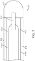
- the distal or first zone or section 121 of a catheter shaft 110 includes a center support member 610 that is encased in a reinforcing sleeve 612.
- the center support member 610 terminates in a rounded tip 617 and is embedded within and connected to the tip 617 by solder or another suitable connection.
- the sleeve 612 maintains steering wires 614a,b (generally 614) in position against the center support member 610 in order to prevent kinking or tangling of the steering wires 614.
- the first zone 121 also includes tubing 616 that surrounds the sleeve 612 and the center support 610, as shown in phantom in FIG. 6 .
- the first zone 121 may optionally include leaf springs that are attached to the center support 610.
- the material of the center support 610 is a high yield strength material having a yield strength that is greater than about 120,000 psi (827370 kPa).
- the internal support member has a yield strength of about 140,000 psi (965266 kPa) and may be made of Type 301 stainless steel.
- Such material attributes advantageously provide increased lateral rigidity and greater resistance to permanent deformation of the distal portion 112 of the catheter shaft 110.
- the material of the center support 610 may be Type 17-7 PH stainless steel, which has a yield strength of 185,000 psi, Type 440C stainless steel, which has a yield strength of 275,000 psi (1896058 kPa) and other suitable high yield strength materials.
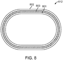
- the reinforcing sleeve 612 encasing the center support 610 may, for example, be made from an inner shrink tube 801, an outer shrink tube 802, and a reinforcing fabric 803 there between.
- the inner and outer tubes 801, 802 may be made of Teflon® polytetrafluoroethylene and the fabric 803 may be a Kevlar® polyaramid material, e.g., in the form of a yarn, which is wrapped in tension over the inner shrink tube 801 as a single spiral about the tube 801 in order to obtain a desired, closely spaced pitch, and the outer shrink tube 802 may be positioned over the reinforcing fabric 803.
- the fabric 803 can be wrapped around the tube 801 to a pitch of about 30 to 35 wraps per inch (e.g., as shown in Fig. 8A ).
- the pitch may be 15 to 20 wraps per inch (e.g., as shown in Fig. 8B ).
- a first shrink step may be performed on the inner shrink tube 801 before the reinforcing fabric 803 is applied thereto, and a second shrink step may be performed on the second shrink tube 802 after the second shrink tube 802 is positioned over the reinforcing fabric. 803.
- the configuration of the sleeve 612 may vary as necessary and depending on the manufacturing method and braid density employed.
- the cross-sectional view of a sleeve 612 may be as shown in Fig. 8 , in which the fabric or braiding 803 extends around the inner tube 801, or the layer 803 may be less dense, e.g., as shown by the braiding pattern employed in Fig. 8B .
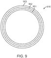
- the tubing 616 may be composite tubing comprised of a fiber-reinforced dual polymer layer.
- the tubing 616 material may depend on the desired bending stiffness and torsional rigidity in the first zone 121.
- stiffer, distal tubing 616 having a higher torsional rigidity, may include an inner layer 901 of 63D Pebax® fiber, a Vectran® liquid crystal polymer reinforcing braid 902, and a 40D outer layer 903, while softer, composite tubing, having a lower torsional rigidity, may include an inner layer 901 of 55D Pebax®, a Vectran® liquid crystal polymer reinforcing braid 902, and a 35D outer layer 903.
- the reinforcing fabric braid 902 may add torsional rigidity to the first zone 121 without the risk of the electrical shorting that a metallic braid would impart.
- the increased torsional strength provided by the braid 902 may help to prevent wind-up of the distal section 112 of the catheter 100 when the handle 130 and/or proximal portion 111 of the catheter 100 are rotated.
- the fabric braid 902 may also add to the lateral or side load strength of the steered distal portion 112 because the braid 902 adds to the torsional strength of the tubing 616.
- the proximal ends of the center support 610 and the reinforcing sleeve 612 are coupled to a flexible inner shaft 620 at the junction between the distal or first zone 121 and the transition or second zone 122.
- the flexible inner shaft 620 may extend from the center support 610 to a handle assembly 130 on the proximal end of the catheter 100 and may comprise a stainless steel coil.
- the proximal end of the center support 610 may fit within the distal end of the inner shaft 620, and the proximal end of the reinforcing sleeve 612 may fit over the distal end of the inner shaft 620, thereby providing a smoother transition between the center support 610 and the coil inner shaft 620.
- the flexible inner shaft or tubing 122 may be enclosed by a stiffening sheath 622, while in the third zone 123 and the fourth zone 124, the flexible inner shaft 620 may be enclosed by a main sheath or tubing 630 (shown in phantom in Fig. 6 ).
- the mechanical properties of the stiffening sheath 622 are such that the stiffness of the second zone 122 is between the stiffness of the first zone 121 and the stiffness of the third zone 123, thus advantageously providing a gradual transition between the first zone 121 and the third zone 123 over the length of the second or transition zone 122.
- the gradual transition achieved with examples over a length of the second zone 122 improves the trackability of the catheter 100.
- the second zone may be comprised of a stiffening sheath 622.
- the inner shaft 620 is covered by the main sheath 630. While the third zone 123 is stiffer than the first and second zones 121, 122, the third zone 123 should be sufficiently compliant or flexible to bend freely as the catheter 100 tracks through the anatomy (e.g., an aortic arch), yet sufficiently stiff or rigid to be highly pushable.
- a main sheath 134 may surround the inner shaft 620, and the main sheath 630 may be comprised of a braided material.
- the fourth zone 124 comprises the proximal portion of the main sheath 630 (which may also form a part of the third zone 123 as shown in Fig. 6 ) and may have increased stiffness compared to the third zone 123.
- the added stiffness of the fourth zone 124 may be accomplished by inserting a stiff metallic rod (not shown) within the catheter shaft 110.
- a stiff metallic rod (not shown) within the catheter shaft 110.
- a long steel wire may be inserted into the proximal shaft for increased rigidity.
- Such a wire may be positioned within a lumen of the inner shaft 620 or between an outer surface of the inner shaft 620 and an inner surface of the main sheath 630.
- the resulting enhanced stiffness of the fourth zone 124 may provide increased pushability, torque, and steering fidelity of the catheter shaft 110.
- a multi-zone structure 120 may have different numbers of zones and different zone profiles, while still having an intermediate or transition zone to provide a smooth or gradual transition between distal and more proximal portions of a shaft.
- different stiffness zones can be formed in various ways, e.g., by adding layers around a catheter, or forming a catheter section of a different material, and/or integrating different internal materials such as an internal distal support member made of Type 301 stainless steel.
- a transition zone may vary in different manners and by different degrees.
- different stiffness zones can be implemented using different catheter materials, diameters, and/or thicknesses and may extend for different lengths.
- the stiffness profile illustrated in Fig. 5 and the materials and dimensions described are provided as one example.
- a stiffness profile may include a single transition zone or multiple transition zones. The stiffness within multiple transition zones may change at the same or different rates.
Landscapes
- Health & Medical Sciences (AREA)
- Life Sciences & Earth Sciences (AREA)
- Engineering & Computer Science (AREA)
- Hematology (AREA)
- Pulmonology (AREA)
- Anesthesiology (AREA)
- Biomedical Technology (AREA)
- Heart & Thoracic Surgery (AREA)
- Biophysics (AREA)
- Animal Behavior & Ethology (AREA)
- General Health & Medical Sciences (AREA)
- Public Health (AREA)
- Veterinary Medicine (AREA)
- Mechanical Engineering (AREA)
- Media Introduction/Drainage Providing Device (AREA)
- Surgical Instruments (AREA)
Applications Claiming Priority (2)
| Application Number | Priority Date | Filing Date | Title |
|---|---|---|---|
| US15408709P | 2009-02-20 | 2009-02-20 | |
| PCT/US2010/024616 WO2010096579A1 (en) | 2009-02-20 | 2010-02-18 | Steerable catheter having intermediate stiffness transition zone |
Publications (2)
| Publication Number | Publication Date |
|---|---|
| EP2398540A1 EP2398540A1 (en) | 2011-12-28 |
| EP2398540B1 true EP2398540B1 (en) | 2018-04-25 |
Family
ID=42077525
Family Applications (1)
| Application Number | Title | Priority Date | Filing Date |
|---|---|---|---|
| EP10705508.9A Active EP2398540B1 (en) | 2009-02-20 | 2010-02-18 | Steerable catheter having intermediate stiffness transition zone |
Country Status (4)
| Country | Link |
|---|---|
| US (2) | US8725228B2 (enExample) |
| EP (1) | EP2398540B1 (enExample) |
| JP (1) | JP5784506B2 (enExample) |
| WO (1) | WO2010096579A1 (enExample) |
Families Citing this family (150)
| Publication number | Priority date | Publication date | Assignee | Title |
|---|---|---|---|---|
| US7653438B2 (en) | 2002-04-08 | 2010-01-26 | Ardian, Inc. | Methods and apparatus for renal neuromodulation |
| US8774913B2 (en) | 2002-04-08 | 2014-07-08 | Medtronic Ardian Luxembourg S.A.R.L. | Methods and apparatus for intravasculary-induced neuromodulation |
| US8150519B2 (en) | 2002-04-08 | 2012-04-03 | Ardian, Inc. | Methods and apparatus for bilateral renal neuromodulation |
| US9955994B2 (en) | 2002-08-02 | 2018-05-01 | Flowcardia, Inc. | Ultrasound catheter having protective feature against breakage |
| US7335180B2 (en) | 2003-11-24 | 2008-02-26 | Flowcardia, Inc. | Steerable ultrasound catheter |
| US7604608B2 (en) * | 2003-01-14 | 2009-10-20 | Flowcardia, Inc. | Ultrasound catheter and methods for making and using same |
| US7758510B2 (en) | 2003-09-19 | 2010-07-20 | Flowcardia, Inc. | Connector for securing ultrasound catheter to transducer |
| WO2006097931A2 (en) | 2005-03-17 | 2006-09-21 | Valtech Cardio, Ltd. | Mitral valve treatment techniques |
| US8951285B2 (en) | 2005-07-05 | 2015-02-10 | Mitralign, Inc. | Tissue anchor, anchoring system and methods of using the same |
| US9883943B2 (en) | 2006-12-05 | 2018-02-06 | Valtech Cardio, Ltd. | Implantation of repair devices in the heart |
| US11259924B2 (en) | 2006-12-05 | 2022-03-01 | Valtech Cardio Ltd. | Implantation of repair devices in the heart |
| US11660190B2 (en) | 2007-03-13 | 2023-05-30 | Edwards Lifesciences Corporation | Tissue anchors, systems and methods, and devices |
| US8382829B1 (en) | 2008-03-10 | 2013-02-26 | Mitralign, Inc. | Method to reduce mitral regurgitation by cinching the commissure of the mitral valve |
| EP2296744B1 (en) | 2008-06-16 | 2019-07-31 | Valtech Cardio, Ltd. | Annuloplasty devices |
| US8241351B2 (en) | 2008-12-22 | 2012-08-14 | Valtech Cardio, Ltd. | Adjustable partial annuloplasty ring and mechanism therefor |
| US10517719B2 (en) | 2008-12-22 | 2019-12-31 | Valtech Cardio, Ltd. | Implantation of repair devices in the heart |
| US8715342B2 (en) | 2009-05-07 | 2014-05-06 | Valtech Cardio, Ltd. | Annuloplasty ring with intra-ring anchoring |
| WO2010073246A2 (en) | 2008-12-22 | 2010-07-01 | Valtech Cardio, Ltd. | Adjustable annuloplasty devices and adjustment mechanisms therefor |
| US8911494B2 (en) | 2009-05-04 | 2014-12-16 | Valtech Cardio, Ltd. | Deployment techniques for annuloplasty ring |
| US8652129B2 (en) | 2008-12-31 | 2014-02-18 | Medtronic Ardian Luxembourg S.A.R.L. | Apparatus, systems, and methods for achieving intravascular, thermally-induced renal neuromodulation |
| US8353956B2 (en) | 2009-02-17 | 2013-01-15 | Valtech Cardio, Ltd. | Actively-engageable movement-restriction mechanism for use with an annuloplasty structure |
| JP5784506B2 (ja) * | 2009-02-20 | 2015-09-24 | ボストン サイエンティフィック サイムド,インコーポレイテッドBoston Scientific Scimed,Inc. | 中間部の剛性を備えた移行領域を有する操作可能なカテーテル |
| US9254123B2 (en) | 2009-04-29 | 2016-02-09 | Hansen Medical, Inc. | Flexible and steerable elongate instruments with shape control and support elements |
| US9968452B2 (en) | 2009-05-04 | 2018-05-15 | Valtech Cardio, Ltd. | Annuloplasty ring delivery cathethers |
| US12485010B2 (en) | 2009-05-07 | 2025-12-02 | Edwards Lifesciences Innovation (Israel) Ltd. | Multiple anchor delivery tool |
| US9180007B2 (en) | 2009-10-29 | 2015-11-10 | Valtech Cardio, Ltd. | Apparatus and method for guide-wire based advancement of an adjustable implant |
| US10098737B2 (en) | 2009-10-29 | 2018-10-16 | Valtech Cardio, Ltd. | Tissue anchor for annuloplasty device |
| EP2506777B1 (en) | 2009-12-02 | 2020-11-25 | Valtech Cardio, Ltd. | Combination of spool assembly coupled to a helical anchor and delivery tool for implantation thereof |
| US8870863B2 (en) | 2010-04-26 | 2014-10-28 | Medtronic Ardian Luxembourg S.A.R.L. | Catheter apparatuses, systems, and methods for renal neuromodulation |
| US20120191107A1 (en) | 2010-09-17 | 2012-07-26 | Tanner Neal A | Systems and methods for positioning an elongate member inside a body |
| US8652033B2 (en) * | 2010-09-23 | 2014-02-18 | Karl Storz Endovision, Inc. | Video stylet with directable tip |
| US9084610B2 (en) | 2010-10-21 | 2015-07-21 | Medtronic Ardian Luxembourg S.A.R.L. | Catheter apparatuses, systems, and methods for renal neuromodulation |
| JP2013544133A (ja) | 2010-10-25 | 2013-12-12 | メドトロニック アーディアン ルクセンブルク ソシエテ ア レスポンサビリテ リミテ | 腎ニューロモジュレーションのためのマルチ電極アレイを有するカテーテル装置ならびに関連のシステムおよび方法 |
| US8721588B2 (en) | 2011-04-15 | 2014-05-13 | DePuy Synthes Products, LLC | Noncircular inner lumen guiding catheter with assisted variable support |
| EP3725269A1 (en) | 2011-06-23 | 2020-10-21 | Valtech Cardio, Ltd. | Closure element for use with annuloplasty structure |
| US10792152B2 (en) | 2011-06-23 | 2020-10-06 | Valtech Cardio, Ltd. | Closed band for percutaneous annuloplasty |
| US20130030363A1 (en) | 2011-07-29 | 2013-01-31 | Hansen Medical, Inc. | Systems and methods utilizing shape sensing fibers |
| US8858623B2 (en) | 2011-11-04 | 2014-10-14 | Valtech Cardio, Ltd. | Implant having multiple rotational assemblies |
| EP3970627B1 (en) | 2011-11-08 | 2023-12-20 | Edwards Lifesciences Innovation (Israel) Ltd. | Controlled steering functionality for implant-delivery tool |
| WO2013088327A1 (en) | 2011-12-12 | 2013-06-20 | David Alon | Heart valve repair device |
| USD715430S1 (en) * | 2012-05-07 | 2014-10-14 | St. Jude Medical, Atrial Fibrillation Division, Inc. | Control handle for a medical device |
| USD715429S1 (en) * | 2012-05-07 | 2014-10-14 | St. Jude Medical, Atrial Fibrillation Division, Inc. | Control handle for a medical device |
| US8888773B2 (en) | 2012-05-11 | 2014-11-18 | Medtronic Ardian Luxembourg S.A.R.L. | Multi-electrode catheter assemblies for renal neuromodulation and associated systems and methods |
| US8998844B2 (en) | 2012-06-04 | 2015-04-07 | St. Jude Medical, Atrial Fibrillation Division, Inc. | Handle extension for an elongate medical device |
| USD726906S1 (en) * | 2012-06-04 | 2015-04-14 | St. Jude Medical, Atrial Fibrillation Division, Inc. | Control handle for a medical device |
| US8998845B2 (en) | 2012-06-04 | 2015-04-07 | St. Jude Medical, Atrial Fibrillation Division, Inc. | Deflection mechanism for an elongate medical device |
| JP5660737B2 (ja) * | 2012-07-20 | 2015-01-28 | 日本ライフライン株式会社 | 電極カテーテルおよびその製造方法 |
| WO2014022716A2 (en) | 2012-08-02 | 2014-02-06 | Flowcardia, Inc. | Ultrasound catheter system |
| CA2885354A1 (en) | 2012-09-29 | 2014-04-03 | Mitralign, Inc. | Plication lock delivery system and method of use thereof |
| EP3578222B1 (en) | 2012-10-22 | 2024-06-19 | Medtronic Ardian Luxembourg S.à.r.l. | Catheters with enhanced flexibility |
| US9044575B2 (en) | 2012-10-22 | 2015-06-02 | Medtronic Adrian Luxembourg S.a.r.l. | Catheters with enhanced flexibility and associated devices, systems, and methods |
| US9949828B2 (en) | 2012-10-23 | 2018-04-24 | Valtech Cardio, Ltd. | Controlled steering functionality for implant-delivery tool |
| EP2911593B1 (en) | 2012-10-23 | 2020-03-25 | Valtech Cardio, Ltd. | Percutaneous tissue anchor techniques |
| US20140148673A1 (en) | 2012-11-28 | 2014-05-29 | Hansen Medical, Inc. | Method of anchoring pullwire directly articulatable region in catheter |
| WO2014087402A1 (en) | 2012-12-06 | 2014-06-12 | Valtech Cardio, Ltd. | Techniques for guide-wire based advancement of a tool |
| WO2014134183A1 (en) | 2013-02-26 | 2014-09-04 | Mitralign, Inc. | Devices and methods for percutaneous tricuspid valve repair |
| US10149720B2 (en) | 2013-03-08 | 2018-12-11 | Auris Health, Inc. | Method, apparatus, and a system for facilitating bending of an instrument in a surgical or medical robotic environment |
| US10449333B2 (en) | 2013-03-14 | 2019-10-22 | Valtech Cardio, Ltd. | Guidewire feeder |
| US10376672B2 (en) | 2013-03-15 | 2019-08-13 | Auris Health, Inc. | Catheter insertion system and method of fabrication |
| US9724195B2 (en) | 2013-03-15 | 2017-08-08 | Mitralign, Inc. | Translation catheters and systems |
| US9066726B2 (en) | 2013-03-15 | 2015-06-30 | Medtronic Ardian Luxembourg S.A.R.L. | Multi-electrode apposition judgment using pressure elements |
| US10548663B2 (en) | 2013-05-18 | 2020-02-04 | Medtronic Ardian Luxembourg S.A.R.L. | Neuromodulation catheters with shafts for enhanced flexibility and control and associated devices, systems, and methods |
| US10070857B2 (en) | 2013-08-31 | 2018-09-11 | Mitralign, Inc. | Devices and methods for locating and implanting tissue anchors at mitral valve commissure |
| US10299793B2 (en) | 2013-10-23 | 2019-05-28 | Valtech Cardio, Ltd. | Anchor magazine |
| EP3689284B1 (en) | 2013-10-24 | 2025-02-26 | Auris Health, Inc. | System for robotic-assisted endolumenal surgery |
| CN110898312B (zh) | 2013-12-20 | 2022-11-15 | 波士顿科学国际有限公司 | 集成导管系统 |
| US9610162B2 (en) | 2013-12-26 | 2017-04-04 | Valtech Cardio, Ltd. | Implantation of flexible implant |
| EP3099377B1 (en) | 2014-01-27 | 2022-03-02 | Medtronic Ireland Manufacturing Unlimited Company | Neuromodulation catheters having jacketed neuromodulation elements and related devices |
| USD726908S1 (en) | 2014-02-06 | 2015-04-14 | St. Jude Medical, Cardiology Division, Inc. | Catheter handle |
| US10736690B2 (en) | 2014-04-24 | 2020-08-11 | Medtronic Ardian Luxembourg S.A.R.L. | Neuromodulation catheters and associated systems and methods |
| US10792464B2 (en) | 2014-07-01 | 2020-10-06 | Auris Health, Inc. | Tool and method for using surgical endoscope with spiral lumens |
| US9744335B2 (en) | 2014-07-01 | 2017-08-29 | Auris Surgical Robotics, Inc. | Apparatuses and methods for monitoring tendons of steerable catheters |
| US9561083B2 (en) | 2014-07-01 | 2017-02-07 | Auris Surgical Robotics, Inc. | Articulating flexible endoscopic tool with roll capabilities |
| US10194893B2 (en) * | 2014-09-26 | 2019-02-05 | BostonScientific Scimed, Inc. | Medical retrieval systems and related methods |
| EP4331503A3 (en) | 2014-10-14 | 2024-06-05 | Edwards Lifesciences Innovation (Israel) Ltd. | Leaflet-restraining techniques |
| WO2016069473A1 (en) * | 2014-10-27 | 2016-05-06 | Qxmedical, Llc | Variable stiffness balloon catheter and related methods |
| WO2016081650A1 (en) | 2014-11-19 | 2016-05-26 | Advanced Cardiac Therapeutics, Inc. | Ablation devices, systems and methods of using a high-resolution electrode assembly |
| WO2016081611A1 (en) | 2014-11-19 | 2016-05-26 | Advanced Cardiac Therapeutics, Inc. | High-resolution mapping of tissue with pacing |
| EP3220844B1 (en) | 2014-11-19 | 2020-11-11 | EPiX Therapeutics, Inc. | Systems for high-resolution mapping of tissue |
| CA2974354C (en) | 2015-01-22 | 2021-11-16 | Hollister Incorporated | Lubricious urinary catheters having varying flexibility |
| US20160256269A1 (en) | 2015-03-05 | 2016-09-08 | Mitralign, Inc. | Devices for treating paravalvular leakage and methods use thereof |
| US9636164B2 (en) | 2015-03-25 | 2017-05-02 | Advanced Cardiac Therapeutics, Inc. | Contact sensing systems and methods |
| US11819636B2 (en) | 2015-03-30 | 2023-11-21 | Auris Health, Inc. | Endoscope pull wire electrical circuit |
| US20160296133A1 (en) * | 2015-04-08 | 2016-10-13 | Oscor Inc. | Diagnostic catheter shaft construction and manufacturing method |
| SG11201708397PA (en) | 2015-04-30 | 2017-11-29 | Valtech Cardio Ltd | Annuloplasty technologies |
| US9827122B2 (en) | 2015-05-04 | 2017-11-28 | Abbott Cardiovascular Systems Inc. | System for a catheter |
| US10398874B2 (en) | 2015-05-29 | 2019-09-03 | Covidien Lp | Catheter distal tip configuration |
| US10357631B2 (en) | 2015-05-29 | 2019-07-23 | Covidien Lp | Catheter with tapering outer diameter |
| US11219740B2 (en) | 2015-05-29 | 2022-01-11 | Covidien Lp | Catheter including tapering coil member |
| US10376673B2 (en) | 2015-06-19 | 2019-08-13 | Evalve, Inc. | Catheter guiding system and methods |
| US10238494B2 (en) | 2015-06-29 | 2019-03-26 | Evalve, Inc. | Self-aligning radiopaque ring |
| US10413408B2 (en) * | 2015-08-06 | 2019-09-17 | Evalve, Inc. | Delivery catheter systems, methods, and devices |
| US10238495B2 (en) | 2015-10-09 | 2019-03-26 | Evalve, Inc. | Delivery catheter handle and methods of use |
| EP3397207B1 (en) | 2015-12-30 | 2026-04-01 | Edwards Lifesciences Corporation | System for reducing tricuspid regurgitation |
| US10751182B2 (en) | 2015-12-30 | 2020-08-25 | Edwards Lifesciences Corporation | System and method for reshaping right heart |
| SG11201807618QA (en) | 2016-03-15 | 2018-10-30 | Epix Therapeutics Inc | Improved devices, systems and methods for irrigated ablation |
| US10702274B2 (en) | 2016-05-26 | 2020-07-07 | Edwards Lifesciences Corporation | Method and system for closing left atrial appendage |
| GB201611910D0 (en) | 2016-07-08 | 2016-08-24 | Valtech Cardio Ltd | Adjustable annuloplasty device with alternating peaks and troughs |
| US10531787B2 (en) | 2016-07-28 | 2020-01-14 | Cook Medical Technologies Llc | Steerable multilumen catheter shaft |
| US10463439B2 (en) | 2016-08-26 | 2019-11-05 | Auris Health, Inc. | Steerable catheter with shaft load distributions |
| US20180140321A1 (en) | 2016-11-23 | 2018-05-24 | C. R. Bard, Inc. | Catheter With Retractable Sheath And Methods Thereof |
| US11596726B2 (en) | 2016-12-17 | 2023-03-07 | C.R. Bard, Inc. | Ultrasound devices for removing clots from catheters and related methods |
| US10582983B2 (en) | 2017-02-06 | 2020-03-10 | C. R. Bard, Inc. | Ultrasonic endovascular catheter with a controllable sheath |
| JP7039174B2 (ja) | 2017-02-28 | 2022-03-22 | キヤノン株式会社 | ワイヤ駆動マニピュレータ |
| US10926060B2 (en) | 2017-03-02 | 2021-02-23 | Covidien Lp | Flexible tip catheter |
| JP6727405B2 (ja) * | 2017-03-31 | 2020-07-22 | Hoya株式会社 | 内視鏡 |
| US11045627B2 (en) | 2017-04-18 | 2021-06-29 | Edwards Lifesciences Corporation | Catheter system with linear actuation control mechanism |
| US10537710B2 (en) | 2017-04-20 | 2020-01-21 | Covidien Lp | Catheter including an inner liner with a flexible distal section |
| EP3614946B1 (en) | 2017-04-27 | 2024-03-20 | EPiX Therapeutics, Inc. | Determining nature of contact between catheter tip and tissue |
| US10716461B2 (en) | 2017-05-17 | 2020-07-21 | Auris Health, Inc. | Exchangeable working channel |
| US10835221B2 (en) | 2017-11-02 | 2020-11-17 | Valtech Cardio, Ltd. | Implant-cinching devices and systems |
| US11135062B2 (en) | 2017-11-20 | 2021-10-05 | Valtech Cardio Ltd. | Cinching of dilated heart muscle |
| WO2019145947A1 (en) | 2018-01-24 | 2019-08-01 | Valtech Cardio, Ltd. | Contraction of an annuloplasty structure |
| EP3743014B1 (en) | 2018-01-26 | 2023-07-19 | Edwards Lifesciences Innovation (Israel) Ltd. | Techniques for facilitating heart valve tethering and chord replacement |
| US12201512B2 (en) * | 2018-03-06 | 2025-01-21 | Mentor Worldwide Llc | Delivery sleeve |
| US11903814B2 (en) | 2018-03-06 | 2024-02-20 | Mentor Worldwide Llc | Delivery sleeve |
| US11311369B2 (en) | 2018-03-06 | 2022-04-26 | Mentor Worldwide Llc | Delivery sleeve |
| EP4344723A3 (en) * | 2018-03-28 | 2024-06-12 | Auris Health, Inc. | Medical instruments with variable bending stiffness profiles |
| CN120000269A (zh) | 2018-07-12 | 2025-05-16 | 爱德华兹生命科学创新(以色列)有限公司 | 瓣环成形系统及其锁定工具 |
| KR102612146B1 (ko) | 2018-08-07 | 2023-12-13 | 아우리스 헬스, 인코포레이티드 | 카테터 제어와의 변형-기반 형상 감지의 조합 |
| EP3840630B1 (en) | 2018-08-23 | 2025-09-10 | NuVera Medical, Inc. | Medical tool positioning devices, systems, and methods of use and manufacture |
| US11179212B2 (en) | 2018-09-26 | 2021-11-23 | Auris Health, Inc. | Articulating medical instruments |
| US11986257B2 (en) | 2018-12-28 | 2024-05-21 | Auris Health, Inc. | Medical instrument with articulable segment |
| US10967151B2 (en) * | 2019-01-01 | 2021-04-06 | Cairdac | Steerable catheter for the implantation of a leadless cardiac capsule |
| US11617627B2 (en) | 2019-03-29 | 2023-04-04 | Auris Health, Inc. | Systems and methods for optical strain sensing in medical instruments |
| AU2020284630A1 (en) | 2019-05-29 | 2021-11-18 | Edwards Lifesciences Innovation (Israel) Ltd. | Tissue anchor handling systems and methods |
| US12220541B2 (en) * | 2019-07-03 | 2025-02-11 | Biosense Webster (Israel) Ltd. | Sensing and mapping catheter for guiding and supporting balloon catheter |
| US12502167B2 (en) | 2019-07-16 | 2025-12-23 | Edwards Lifesciences Corporation | Tissue remodeling systems and methods |
| CA3141295A1 (en) | 2019-07-23 | 2021-01-28 | Valtech Cardio, Ltd. | Contraction of an annuloplasty structure |
| US12364606B2 (en) | 2019-07-23 | 2025-07-22 | Edwards Lifesciences Innovation (Israel) Ltd. | Fluoroscopic visualization of heart valve anatomy |
| JP7660914B2 (ja) * | 2019-08-02 | 2025-04-14 | ビザラメド, インコーポレイテッド | 操向可能シース |
| KR20220050151A (ko) | 2019-08-15 | 2022-04-22 | 아우리스 헬스, 인코포레이티드 | 다수의 굽힘 섹션을 갖는 의료 장치 |
| WO2021038560A1 (en) | 2019-08-28 | 2021-03-04 | Valtech Cardio, Ltd. | Low-profile steerable catheter |
| EP4021350B1 (en) | 2019-08-30 | 2024-12-18 | Edwards Lifesciences Innovation (Israel) Ltd. | Anchor channel tip |
| KR20220066398A (ko) | 2019-09-25 | 2022-05-24 | 카디악 임플란츠 엘엘씨 | 심장 판막 고리 감소 시스템 |
| KR20220122966A (ko) | 2019-10-29 | 2022-09-05 | 에드워즈 라이프사이언시스 이노베이션 (이스라엘) 리미티드 | 고리 성형술 및 조직 앵커 기술 |
| CN114901188B (zh) | 2019-12-31 | 2026-02-17 | 奥瑞斯健康公司 | 动态滑轮系统 |
| US11918764B2 (en) | 2020-02-21 | 2024-03-05 | Boston Scientific Scimed, Inc. | Directional enhancement feature for articulation catheter |
| EP4096529B1 (en) | 2020-03-23 | 2025-05-07 | Edwards Lifesciences Innovation (Israel) Ltd. | Self-locking winch |
| US11844909B2 (en) | 2020-03-23 | 2023-12-19 | Boston Scientific Scimed, Inc. | Guide catheter with reinforcing member |
| JP2023527304A (ja) | 2020-05-20 | 2023-06-28 | カーディアック・インプランツ・エルエルシー | 心臓弁輪に打ち込まれるアンカそれぞれを独立的に制御することによる心臓弁輪の直径の減少 |
| EP4606322A1 (en) | 2020-06-19 | 2025-08-27 | Edwards Lifesciences Innovation (Israel) Ltd. | Self-stopping tissue anchors |
| US11951026B2 (en) * | 2020-06-30 | 2024-04-09 | DePuy Synthes Products, Inc. | Implantable medical device detachment system with flexible braid section |
| US11786360B2 (en) | 2020-07-01 | 2023-10-17 | Mentor Worldwide Llc | Encoded cinching mechanism for use with an implant delivery sleeve |
| US12472330B2 (en) | 2020-07-08 | 2025-11-18 | Kaneka Corporation | Catheter |
| US12544536B2 (en) * | 2020-07-08 | 2026-02-10 | Kaneka Corporation | Electrode catheter |
| US20240316314A1 (en) * | 2021-08-19 | 2024-09-26 | Kaneka Corporation | Catheter |
| US20240009424A1 (en) * | 2022-07-08 | 2024-01-11 | Scientia Vascular, Inc. | Extendable lumen catheter device |
| CN121889188A (zh) * | 2023-09-13 | 2026-04-17 | 丹尼尔·以斯拉·沃尔兹曼 | 包括具有可调弯性的可变刚度导管的血管内系统 |
| WO2025244764A1 (en) * | 2024-05-19 | 2025-11-27 | Autonomix Medical, Inc. | Medical devices configured for therapeutic electroporation with adjustable sections of an elongate member |
Family Cites Families (84)
| Publication number | Priority date | Publication date | Assignee | Title |
|---|---|---|---|---|
| US4921483A (en) * | 1985-12-19 | 1990-05-01 | Leocor, Inc. | Angioplasty catheter |
| US4739768B2 (en) * | 1986-06-02 | 1995-10-24 | Target Therapeutics Inc | Catheter for guide-wire tracking |
| US5231995A (en) * | 1986-11-14 | 1993-08-03 | Desai Jawahar M | Method for catheter mapping and ablation |
| US4940064A (en) * | 1986-11-14 | 1990-07-10 | Desai Jawahar M | Catheter for mapping and ablation and method therefor |
| US4922912A (en) * | 1987-10-21 | 1990-05-08 | Hideto Watanabe | MAP catheter |
| US5254088A (en) * | 1990-02-02 | 1993-10-19 | Ep Technologies, Inc. | Catheter steering mechanism |
| US5273535A (en) * | 1991-11-08 | 1993-12-28 | Ep Technologies, Inc. | Catheter with electrode tip having asymmetric left and right curve configurations |
| US6413234B1 (en) * | 1990-02-02 | 2002-07-02 | Ep Technologies, Inc. | Assemblies for creating compound curves in distal catheter regions |
| US5891088A (en) | 1990-02-02 | 1999-04-06 | Ep Technologies, Inc. | Catheter steering assembly providing asymmetric left and right curve configurations |
| US5217482A (en) * | 1990-08-28 | 1993-06-08 | Scimed Life Systems, Inc. | Balloon catheter with distal guide wire lumen |
| US5329923A (en) * | 1991-02-15 | 1994-07-19 | Lundquist Ingemar H | Torquable catheter |
| US5766151A (en) * | 1991-07-16 | 1998-06-16 | Heartport, Inc. | Endovascular system for arresting the heart |
| US5308342A (en) * | 1991-08-07 | 1994-05-03 | Target Therapeutics, Inc. | Variable stiffness catheter |
| US5257451A (en) | 1991-11-08 | 1993-11-02 | Ep Technologies, Inc. | Method of making durable sleeve for enclosing a bendable electrode tip assembly |
| US5275162A (en) * | 1991-11-08 | 1994-01-04 | Ep Technologies, Inc. | Valve mapping catheter |
| US5354297A (en) * | 1992-02-14 | 1994-10-11 | Boaz Avitall | Biplanar deflectable catheter for arrhythmogenic tissue ablation |
| US5437288A (en) * | 1992-09-04 | 1995-08-01 | Mayo Foundation For Medical Education And Research | Flexible catheter guidewire |
| JP3310031B2 (ja) * | 1992-10-23 | 2002-07-29 | テルモ株式会社 | カテーテルチューブ |
| US5706809A (en) * | 1993-01-29 | 1998-01-13 | Cardima, Inc. | Method and system for using multiple intravascular sensing devices to detect electrical activity |
| US5462544A (en) * | 1993-05-05 | 1995-10-31 | Energy Life System Corporation | Continuous heart tissue mapping and lasing catheter |
| US5928191A (en) * | 1993-07-30 | 1999-07-27 | E.P. Technologies, Inc. | Variable curve electrophysiology catheter |
| US5562619A (en) * | 1993-08-19 | 1996-10-08 | Boston Scientific Corporation | Deflectable catheter |
| US5651786A (en) * | 1993-09-20 | 1997-07-29 | Abela Laser Systems, Inc. | Mapping catheter and method |
| WO1995010318A1 (en) | 1993-10-14 | 1995-04-20 | Ep Technologies, Inc. | Electrode elements for forming lesion patterns |
| US5921924A (en) * | 1993-12-03 | 1999-07-13 | Avitall; Boaz | Mapping and ablation catheter system utilizing multiple control elements |
| US5487385A (en) * | 1993-12-03 | 1996-01-30 | Avitall; Boaz | Atrial mapping and ablation catheter system |
| US5730127A (en) * | 1993-12-03 | 1998-03-24 | Avitall; Boaz | Mapping and ablation catheter system |
| WO1995024236A1 (en) * | 1994-03-10 | 1995-09-14 | Schneider (Usa) Inc. | Catheter having shaft of varying stiffness |
| JP3587567B2 (ja) * | 1994-09-08 | 2004-11-10 | テルモ株式会社 | カテーテルチューブ |
| WO1996015819A1 (en) * | 1994-11-23 | 1996-05-30 | Navarre Biomedical, Ltd. | Flexible catheter |
| WO1996026675A1 (en) * | 1995-02-28 | 1996-09-06 | Boston Scientific Corporation | Deflectable catheter for ablating cardiac tissue |
| US5984907A (en) | 1995-06-05 | 1999-11-16 | Ep Technologies, Inc. | Transition sleeve assembly for catheters |
| US5824005A (en) * | 1995-08-22 | 1998-10-20 | Board Of Regents, The University Of Texas System | Maneuverable electrophysiology catheter for percutaneous or intraoperative ablation of cardiac arrhythmias |
| US6144870A (en) * | 1996-10-21 | 2000-11-07 | Procath Corporation | Catheter with improved electrodes and method of fabrication |
| US6002955A (en) * | 1996-11-08 | 1999-12-14 | Medtronic, Inc. | Stabilized electrophysiology catheter and method for use |
| US5785706A (en) * | 1996-11-18 | 1998-07-28 | Daig Corporation | Nonsurgical mapping and treatment of cardiac arrhythmia using a catheter contained within a guiding introducer containing openings |
| US20020026145A1 (en) * | 1997-03-06 | 2002-02-28 | Bagaoisan Celso J. | Method and apparatus for emboli containment |
| US6093177A (en) * | 1997-03-07 | 2000-07-25 | Cardiogenesis Corporation | Catheter with flexible intermediate section |
| US5827278A (en) * | 1997-05-20 | 1998-10-27 | Cordis Webster, Inc. | Deflectable tip electrode catheter with nylon stiffener and compression coil |
| US5964757A (en) * | 1997-09-05 | 1999-10-12 | Cordis Webster, Inc. | Steerable direct myocardial revascularization catheter |
| EP0900547B1 (en) * | 1997-09-05 | 2007-05-30 | Biosense Webster, Inc. | Steerable catheter for detecting and revascularizing ischemic myocardial tissue |
| JP3469058B2 (ja) * | 1997-09-12 | 2003-11-25 | エクセルメデイ株式会社 | 電極カテーテル |
| EP1023913B1 (en) * | 1997-10-08 | 2004-12-29 | Kaneka Corporation | Balloon catheter and method of production thereof |
| JP3764569B2 (ja) * | 1997-10-16 | 2006-04-12 | テルモ株式会社 | 医療用チューブ |
| US6308090B1 (en) * | 1998-03-09 | 2001-10-23 | Irvine Biomedical, Inc. | Devices and methods for coronary sinus mapping |
| US6171296B1 (en) * | 1998-04-28 | 2001-01-09 | Microtherapeutics, Inc. | Flow directed catheter |
| US6217565B1 (en) * | 1998-07-16 | 2001-04-17 | Mark Cohen | Reinforced variable stiffness tubing |
| US6547779B2 (en) * | 1998-07-22 | 2003-04-15 | Endovasix, Inc. | Flexible flow apparatus and method for the disruption of occlusions |
| US6210406B1 (en) | 1998-12-03 | 2001-04-03 | Cordis Webster, Inc. | Split tip electrode catheter and signal processing RF ablation system |
| JP4700173B2 (ja) * | 1999-07-16 | 2011-06-15 | テルモ株式会社 | カテーテルの製造方法およびカテーテル |
| US6556873B1 (en) * | 1999-11-29 | 2003-04-29 | Medtronic, Inc. | Medical electrical lead having variable bending stiffness |
| JP2001178826A (ja) * | 1999-12-27 | 2001-07-03 | Hirakawa Hewtech Corp | カテーテル用チューブ |
| US6711428B2 (en) * | 2000-01-27 | 2004-03-23 | Biosense Webster, Inc. | Catheter having mapping assembly |
| DE60134739D1 (de) * | 2000-05-16 | 2008-08-21 | Atrionix Inc | Katheter mit lenkbarer spitze und spurausrichtungsmechanismus eines führungsdrahts |
| JP2001321445A (ja) * | 2000-05-17 | 2001-11-20 | Mitsubishi Cable Ind Ltd | 可撓性チューブ |
| JP2002028244A (ja) * | 2000-07-12 | 2002-01-29 | Hitachi Cable Ltd | カテーテルチューブ及びその製造方法 |
| US6746446B1 (en) * | 2000-08-04 | 2004-06-08 | Cardima, Inc. | Electrophysiological device for the isthmus |
| US6926669B1 (en) * | 2000-10-10 | 2005-08-09 | Medtronic, Inc. | Heart wall ablation/mapping catheter and method |
| US7081114B2 (en) * | 2000-11-29 | 2006-07-25 | St. Jude Medical, Atrial Fibrillation Division, Inc. | Electrophysiology/ablation catheter having lariat configuration of variable radius |
| JP2002272850A (ja) * | 2001-03-19 | 2002-09-24 | Hitachi Cable Ltd | カテーテルチューブ及びその製造方法 |
| DE60211896T2 (de) * | 2001-05-21 | 2007-05-10 | Medtronic, Inc., Minneapolis | Verformbare langgestreckte medizinische vorrichtung |
| US6716207B2 (en) * | 2001-05-22 | 2004-04-06 | Scimed Life Systems, Inc. | Torqueable and deflectable medical device shaft |
| US6869414B2 (en) * | 2002-03-22 | 2005-03-22 | Cardiac Pacemakers, Inc. | Pre-shaped catheter with proximal articulation and pre-formed distal end |
| US6866662B2 (en) * | 2002-07-23 | 2005-03-15 | Biosense Webster, Inc. | Ablation catheter having stabilizing array |
| AU2003277361A1 (en) * | 2002-10-10 | 2004-05-04 | Micro Therapeutics, Inc. | Wire braid-reinforced microcatheter |
| US7013169B2 (en) * | 2003-01-27 | 2006-03-14 | Cardiac Pacemakers, Inc. | Dual steer preshaped catheter |
| WO2004075952A2 (en) * | 2003-02-26 | 2004-09-10 | Boston Scientific Limited | Balloon catheter |
| US7727442B2 (en) * | 2003-07-10 | 2010-06-01 | Boston Scientific Scimed, Inc. | Medical device tubing with discrete orientation regions |
| US20050033136A1 (en) | 2003-08-01 | 2005-02-10 | Assaf Govari | Catheter with electrode strip |
| US7077823B2 (en) | 2003-11-19 | 2006-07-18 | Biosense Webster, Inc. | Bidirectional steerable catheter with slidable mated puller wires |
| US7412273B2 (en) * | 2004-11-15 | 2008-08-12 | Biosense Webster, Inc. | Soft linear mapping catheter with stabilizing tip |
| US7496394B2 (en) * | 2004-11-15 | 2009-02-24 | Biosense Webster, Inc. | Internal reference coronary sinus catheter |
| JP4647299B2 (ja) * | 2004-12-09 | 2011-03-09 | 株式会社カネカ | 医療用カテーテルチューブならびにその製造方法 |
| EP1825879A1 (en) * | 2004-12-09 | 2007-08-29 | Kaneka Corporation | Medical catheter tube and process for producing the same |
| EP1866019B1 (en) * | 2005-02-22 | 2017-10-25 | Cardiofocus, Inc. | Deflectable sheath catheters |
| JP2006288943A (ja) * | 2005-04-14 | 2006-10-26 | Kaneka Corp | 医療用カテーテルチューブならびにその製造方法 |
| JP2006333966A (ja) * | 2005-05-31 | 2006-12-14 | Kaneka Corp | 塞栓コイルデリバリー用カテーテルチューブ |
| US9445784B2 (en) * | 2005-09-22 | 2016-09-20 | Boston Scientific Scimed, Inc | Intravascular ultrasound catheter |
| US7892186B2 (en) * | 2005-12-09 | 2011-02-22 | Heraeus Materials S.A. | Handle and articulator system and method |
| US8246574B2 (en) * | 2006-04-21 | 2012-08-21 | Abbott Laboratories | Support catheter |
| AU2007254126A1 (en) * | 2006-05-19 | 2007-11-29 | Conmed Endoscopic Technologies, Inc. | Steerable medical instrument |
| JP2007319594A (ja) * | 2006-06-05 | 2007-12-13 | Kaneka Corp | 医療用カテーテルチューブ |
| US7774039B2 (en) * | 2006-09-05 | 2010-08-10 | Boston Scientific Scimed, Inc. | Multi-bend steerable mapping catheter |
| JP5784506B2 (ja) * | 2009-02-20 | 2015-09-24 | ボストン サイエンティフィック サイムド,インコーポレイテッドBoston Scientific Scimed,Inc. | 中間部の剛性を備えた移行領域を有する操作可能なカテーテル |
-
2010
- 2010-02-18 JP JP2011551220A patent/JP5784506B2/ja not_active Expired - Fee Related
- 2010-02-18 WO PCT/US2010/024616 patent/WO2010096579A1/en not_active Ceased
- 2010-02-18 US US12/708,114 patent/US8725228B2/en active Active
- 2010-02-18 EP EP10705508.9A patent/EP2398540B1/en active Active
-
2014
- 2014-05-13 US US14/276,761 patent/US20140249510A1/en not_active Abandoned
Non-Patent Citations (1)
| Title |
|---|
| None * |
Also Published As
| Publication number | Publication date |
|---|---|
| JP5784506B2 (ja) | 2015-09-24 |
| WO2010096579A1 (en) | 2010-08-26 |
| JP2012518477A (ja) | 2012-08-16 |
| EP2398540A1 (en) | 2011-12-28 |
| US20140249510A1 (en) | 2014-09-04 |
| US8725228B2 (en) | 2014-05-13 |
| US20100217184A1 (en) | 2010-08-26 |
Similar Documents
| Publication | Publication Date | Title |
|---|---|---|
| EP2398540B1 (en) | Steerable catheter having intermediate stiffness transition zone | |
| JP6621879B2 (ja) | 両方向性作動用の単一牽引ワイヤを備えた二重ループラッソー | |
| US11617861B2 (en) | Triple coil catheter support | |
| EP1326550B1 (en) | Heart wall ablation/mapping catheter | |
| US6869414B2 (en) | Pre-shaped catheter with proximal articulation and pre-formed distal end | |
| EP3122276B1 (en) | Asymmetric catheter curve shapes | |
| US5984907A (en) | Transition sleeve assembly for catheters | |
| EP3412238B1 (en) | Catheter with atraumatic tip | |
| US11628009B2 (en) | EP catheter with trained support member, and related methods | |
| US20020169444A1 (en) | Catheter having continuous braided electrode | |
| AU2015367281A1 (en) | An improved catheter and method of manufacture thereof | |
| EP3381395B1 (en) | Catheter with floating curvature | |
| EP3813706B1 (en) | Unibody intravascular catheter shaft | |
| IL317647A (en) | Over-The-Wire Medical Tool Positioning Devices, Systems, and Methods of Use and Manufacture |
Legal Events
| Date | Code | Title | Description |
|---|---|---|---|
| PUAI | Public reference made under article 153(3) epc to a published international application that has entered the european phase |
Free format text: ORIGINAL CODE: 0009012 |
|
| 17P | Request for examination filed |
Effective date: 20110912 |
|
| AK | Designated contracting states |
Kind code of ref document: A1 Designated state(s): AT BE BG CH CY CZ DE DK EE ES FI FR GB GR HR HU IE IS IT LI LT LU LV MC MK MT NL NO PL PT RO SE SI SK SM TR |
|
| DAX | Request for extension of the european patent (deleted) | ||
| STAA | Information on the status of an ep patent application or granted ep patent |
Free format text: STATUS: EXAMINATION IS IN PROGRESS |
|
| 17Q | First examination report despatched |
Effective date: 20161206 |
|
| GRAP | Despatch of communication of intention to grant a patent |
Free format text: ORIGINAL CODE: EPIDOSNIGR1 |
|
| STAA | Information on the status of an ep patent application or granted ep patent |
Free format text: STATUS: GRANT OF PATENT IS INTENDED |
|
| INTG | Intention to grant announced |
Effective date: 20171006 |
|
| GRAJ | Information related to disapproval of communication of intention to grant by the applicant or resumption of examination proceedings by the epo deleted |
Free format text: ORIGINAL CODE: EPIDOSDIGR1 |
|
| STAA | Information on the status of an ep patent application or granted ep patent |
Free format text: STATUS: EXAMINATION IS IN PROGRESS |
|
| GRAA | (expected) grant |
Free format text: ORIGINAL CODE: 0009210 |
|
| GRAR | Information related to intention to grant a patent recorded |
Free format text: ORIGINAL CODE: EPIDOSNIGR71 |
|
| GRAS | Grant fee paid |
Free format text: ORIGINAL CODE: EPIDOSNIGR3 |
|
| STAA | Information on the status of an ep patent application or granted ep patent |
Free format text: STATUS: THE PATENT HAS BEEN GRANTED |
|
| INTC | Intention to grant announced (deleted) | ||
| AK | Designated contracting states |
Kind code of ref document: B1 Designated state(s): AT BE BG CH CY CZ DE DK EE ES FI FR GB GR HR HU IE IS IT LI LT LU LV MC MK MT NL NO PL PT RO SE SI SK SM TR |
|
| INTG | Intention to grant announced |
Effective date: 20180316 |
|
| REG | Reference to a national code |
Ref country code: GB Ref legal event code: FG4D |
|
| REG | Reference to a national code |
Ref country code: CH Ref legal event code: EP |
|
| REG | Reference to a national code |
Ref country code: AT Ref legal event code: REF Ref document number: 992231 Country of ref document: AT Kind code of ref document: T Effective date: 20180515 |
|
| REG | Reference to a national code |
Ref country code: IE Ref legal event code: FG4D |
|
| REG | Reference to a national code |
Ref country code: DE Ref legal event code: R096 Ref document number: 602010050163 Country of ref document: DE |
|
| REG | Reference to a national code |
Ref country code: NL Ref legal event code: MP Effective date: 20180425 |
|
| REG | Reference to a national code |
Ref country code: LT Ref legal event code: MG4D |
|
| PG25 | Lapsed in a contracting state [announced via postgrant information from national office to epo] |
Ref country code: NL Free format text: LAPSE BECAUSE OF FAILURE TO SUBMIT A TRANSLATION OF THE DESCRIPTION OR TO PAY THE FEE WITHIN THE PRESCRIBED TIME-LIMIT Effective date: 20180425 |
|
| PG25 | Lapsed in a contracting state [announced via postgrant information from national office to epo] |
Ref country code: SE Free format text: LAPSE BECAUSE OF FAILURE TO SUBMIT A TRANSLATION OF THE DESCRIPTION OR TO PAY THE FEE WITHIN THE PRESCRIBED TIME-LIMIT Effective date: 20180425 Ref country code: FI Free format text: LAPSE BECAUSE OF FAILURE TO SUBMIT A TRANSLATION OF THE DESCRIPTION OR TO PAY THE FEE WITHIN THE PRESCRIBED TIME-LIMIT Effective date: 20180425 Ref country code: BG Free format text: LAPSE BECAUSE OF FAILURE TO SUBMIT A TRANSLATION OF THE DESCRIPTION OR TO PAY THE FEE WITHIN THE PRESCRIBED TIME-LIMIT Effective date: 20180725 Ref country code: NO Free format text: LAPSE BECAUSE OF FAILURE TO SUBMIT A TRANSLATION OF THE DESCRIPTION OR TO PAY THE FEE WITHIN THE PRESCRIBED TIME-LIMIT Effective date: 20180725 Ref country code: PL Free format text: LAPSE BECAUSE OF FAILURE TO SUBMIT A TRANSLATION OF THE DESCRIPTION OR TO PAY THE FEE WITHIN THE PRESCRIBED TIME-LIMIT Effective date: 20180425 Ref country code: ES Free format text: LAPSE BECAUSE OF FAILURE TO SUBMIT A TRANSLATION OF THE DESCRIPTION OR TO PAY THE FEE WITHIN THE PRESCRIBED TIME-LIMIT Effective date: 20180425 Ref country code: LT Free format text: LAPSE BECAUSE OF FAILURE TO SUBMIT A TRANSLATION OF THE DESCRIPTION OR TO PAY THE FEE WITHIN THE PRESCRIBED TIME-LIMIT Effective date: 20180425 |
|
| PG25 | Lapsed in a contracting state [announced via postgrant information from national office to epo] |
Ref country code: GR Free format text: LAPSE BECAUSE OF FAILURE TO SUBMIT A TRANSLATION OF THE DESCRIPTION OR TO PAY THE FEE WITHIN THE PRESCRIBED TIME-LIMIT Effective date: 20180726 Ref country code: HR Free format text: LAPSE BECAUSE OF FAILURE TO SUBMIT A TRANSLATION OF THE DESCRIPTION OR TO PAY THE FEE WITHIN THE PRESCRIBED TIME-LIMIT Effective date: 20180425 Ref country code: LV Free format text: LAPSE BECAUSE OF FAILURE TO SUBMIT A TRANSLATION OF THE DESCRIPTION OR TO PAY THE FEE WITHIN THE PRESCRIBED TIME-LIMIT Effective date: 20180425 |
|
| REG | Reference to a national code |
Ref country code: AT Ref legal event code: MK05 Ref document number: 992231 Country of ref document: AT Kind code of ref document: T Effective date: 20180425 |
|
| PG25 | Lapsed in a contracting state [announced via postgrant information from national office to epo] |
Ref country code: PT Free format text: LAPSE BECAUSE OF FAILURE TO SUBMIT A TRANSLATION OF THE DESCRIPTION OR TO PAY THE FEE WITHIN THE PRESCRIBED TIME-LIMIT Effective date: 20180827 |
|
| REG | Reference to a national code |
Ref country code: DE Ref legal event code: R097 Ref document number: 602010050163 Country of ref document: DE |
|
| PG25 | Lapsed in a contracting state [announced via postgrant information from national office to epo] |
Ref country code: RO Free format text: LAPSE BECAUSE OF FAILURE TO SUBMIT A TRANSLATION OF THE DESCRIPTION OR TO PAY THE FEE WITHIN THE PRESCRIBED TIME-LIMIT Effective date: 20180425 Ref country code: AT Free format text: LAPSE BECAUSE OF FAILURE TO SUBMIT A TRANSLATION OF THE DESCRIPTION OR TO PAY THE FEE WITHIN THE PRESCRIBED TIME-LIMIT Effective date: 20180425 Ref country code: CZ Free format text: LAPSE BECAUSE OF FAILURE TO SUBMIT A TRANSLATION OF THE DESCRIPTION OR TO PAY THE FEE WITHIN THE PRESCRIBED TIME-LIMIT Effective date: 20180425 Ref country code: EE Free format text: LAPSE BECAUSE OF FAILURE TO SUBMIT A TRANSLATION OF THE DESCRIPTION OR TO PAY THE FEE WITHIN THE PRESCRIBED TIME-LIMIT Effective date: 20180425 Ref country code: DK Free format text: LAPSE BECAUSE OF FAILURE TO SUBMIT A TRANSLATION OF THE DESCRIPTION OR TO PAY THE FEE WITHIN THE PRESCRIBED TIME-LIMIT Effective date: 20180425 Ref country code: SK Free format text: LAPSE BECAUSE OF FAILURE TO SUBMIT A TRANSLATION OF THE DESCRIPTION OR TO PAY THE FEE WITHIN THE PRESCRIBED TIME-LIMIT Effective date: 20180425 |
|
| PG25 | Lapsed in a contracting state [announced via postgrant information from national office to epo] |
Ref country code: IT Free format text: LAPSE BECAUSE OF FAILURE TO SUBMIT A TRANSLATION OF THE DESCRIPTION OR TO PAY THE FEE WITHIN THE PRESCRIBED TIME-LIMIT Effective date: 20180425 Ref country code: SM Free format text: LAPSE BECAUSE OF FAILURE TO SUBMIT A TRANSLATION OF THE DESCRIPTION OR TO PAY THE FEE WITHIN THE PRESCRIBED TIME-LIMIT Effective date: 20180425 |
|
| PLBE | No opposition filed within time limit |
Free format text: ORIGINAL CODE: 0009261 |
|
| STAA | Information on the status of an ep patent application or granted ep patent |
Free format text: STATUS: NO OPPOSITION FILED WITHIN TIME LIMIT |
|
| 26N | No opposition filed |
Effective date: 20190128 |
|
| PG25 | Lapsed in a contracting state [announced via postgrant information from national office to epo] |
Ref country code: SI Free format text: LAPSE BECAUSE OF FAILURE TO SUBMIT A TRANSLATION OF THE DESCRIPTION OR TO PAY THE FEE WITHIN THE PRESCRIBED TIME-LIMIT Effective date: 20180425 |
|
| REG | Reference to a national code |
Ref country code: CH Ref legal event code: PL |
|
| PG25 | Lapsed in a contracting state [announced via postgrant information from national office to epo] |
Ref country code: MC Free format text: LAPSE BECAUSE OF FAILURE TO SUBMIT A TRANSLATION OF THE DESCRIPTION OR TO PAY THE FEE WITHIN THE PRESCRIBED TIME-LIMIT Effective date: 20180425 Ref country code: LU Free format text: LAPSE BECAUSE OF NON-PAYMENT OF DUE FEES Effective date: 20190218 |
|
| REG | Reference to a national code |
Ref country code: BE Ref legal event code: MM Effective date: 20190228 |
|
| REG | Reference to a national code |
Ref country code: IE Ref legal event code: MM4A |
|
| PG25 | Lapsed in a contracting state [announced via postgrant information from national office to epo] |
Ref country code: LI Free format text: LAPSE BECAUSE OF NON-PAYMENT OF DUE FEES Effective date: 20190228 Ref country code: CH Free format text: LAPSE BECAUSE OF NON-PAYMENT OF DUE FEES Effective date: 20190228 |
|
| PG25 | Lapsed in a contracting state [announced via postgrant information from national office to epo] |
Ref country code: IE Free format text: LAPSE BECAUSE OF NON-PAYMENT OF DUE FEES Effective date: 20190218 |
|
| PG25 | Lapsed in a contracting state [announced via postgrant information from national office to epo] |
Ref country code: BE Free format text: LAPSE BECAUSE OF NON-PAYMENT OF DUE FEES Effective date: 20190228 |
|
| PG25 | Lapsed in a contracting state [announced via postgrant information from national office to epo] |
Ref country code: TR Free format text: LAPSE BECAUSE OF FAILURE TO SUBMIT A TRANSLATION OF THE DESCRIPTION OR TO PAY THE FEE WITHIN THE PRESCRIBED TIME-LIMIT Effective date: 20180425 |
|
| PG25 | Lapsed in a contracting state [announced via postgrant information from national office to epo] |
Ref country code: MT Free format text: LAPSE BECAUSE OF NON-PAYMENT OF DUE FEES Effective date: 20190218 |
|
| PG25 | Lapsed in a contracting state [announced via postgrant information from national office to epo] |
Ref country code: CY Free format text: LAPSE BECAUSE OF FAILURE TO SUBMIT A TRANSLATION OF THE DESCRIPTION OR TO PAY THE FEE WITHIN THE PRESCRIBED TIME-LIMIT Effective date: 20180425 |
|
| PG25 | Lapsed in a contracting state [announced via postgrant information from national office to epo] |
Ref country code: IS Free format text: LAPSE BECAUSE OF FAILURE TO SUBMIT A TRANSLATION OF THE DESCRIPTION OR TO PAY THE FEE WITHIN THE PRESCRIBED TIME-LIMIT Effective date: 20180825 |
|
| PG25 | Lapsed in a contracting state [announced via postgrant information from national office to epo] |
Ref country code: HU Free format text: LAPSE BECAUSE OF FAILURE TO SUBMIT A TRANSLATION OF THE DESCRIPTION OR TO PAY THE FEE WITHIN THE PRESCRIBED TIME-LIMIT; INVALID AB INITIO Effective date: 20100218 |
|
| PG25 | Lapsed in a contracting state [announced via postgrant information from national office to epo] |
Ref country code: MK Free format text: LAPSE BECAUSE OF FAILURE TO SUBMIT A TRANSLATION OF THE DESCRIPTION OR TO PAY THE FEE WITHIN THE PRESCRIBED TIME-LIMIT Effective date: 20180425 |
|
| PGFP | Annual fee paid to national office [announced via postgrant information from national office to epo] |
Ref country code: GB Payment date: 20240123 Year of fee payment: 15 |
|
| PGFP | Annual fee paid to national office [announced via postgrant information from national office to epo] |
Ref country code: FR Payment date: 20240123 Year of fee payment: 15 |
|
| GBPC | Gb: european patent ceased through non-payment of renewal fee |
Effective date: 20250218 |
|
| PG25 | Lapsed in a contracting state [announced via postgrant information from national office to epo] |
Ref country code: GB Free format text: LAPSE BECAUSE OF NON-PAYMENT OF DUE FEES Effective date: 20250218 |
|
| PG25 | Lapsed in a contracting state [announced via postgrant information from national office to epo] |
Ref country code: FR Free format text: LAPSE BECAUSE OF NON-PAYMENT OF DUE FEES Effective date: 20250228 |
|
| PGFP | Annual fee paid to national office [announced via postgrant information from national office to epo] |
Ref country code: DE Payment date: 20260121 Year of fee payment: 17 |