EP2398084B1 - Light-emitting element, light-emitting device comprising light-emitting element, and method for manufacturing light-emitting element - Google Patents
Light-emitting element, light-emitting device comprising light-emitting element, and method for manufacturing light-emitting element Download PDFInfo
- Publication number
- EP2398084B1 EP2398084B1 EP10741076.3A EP10741076A EP2398084B1 EP 2398084 B1 EP2398084 B1 EP 2398084B1 EP 10741076 A EP10741076 A EP 10741076A EP 2398084 B1 EP2398084 B1 EP 2398084B1
- Authority
- EP
- European Patent Office
- Prior art keywords
- light
- bank
- recess
- layer
- charge injection
- Prior art date
- Legal status (The legal status is an assumption and is not a legal conclusion. Google has not performed a legal analysis and makes no representation as to the accuracy of the status listed.)
- Active
Links
- 238000000034 method Methods 0.000 title claims description 21
- 238000004519 manufacturing process Methods 0.000 title claims description 16
- 238000002347 injection Methods 0.000 claims description 75
- 239000007924 injection Substances 0.000 claims description 75
- 239000000463 material Substances 0.000 claims description 44
- 230000002093 peripheral effect Effects 0.000 claims description 37
- 150000002736 metal compounds Chemical class 0.000 claims description 13
- 229910052751 metal Inorganic materials 0.000 claims description 10
- 239000002184 metal Substances 0.000 claims description 10
- 239000011810 insulating material Substances 0.000 claims description 6
- 239000007788 liquid Substances 0.000 claims description 6
- 238000010438 heat treatment Methods 0.000 claims description 5
- 229910044991 metal oxide Inorganic materials 0.000 claims description 4
- 150000004706 metal oxides Chemical class 0.000 claims description 4
- 150000004767 nitrides Chemical class 0.000 claims description 4
- 239000012530 fluid Substances 0.000 claims description 3
- 239000010410 layer Substances 0.000 description 134
- -1 polyethylene Polymers 0.000 description 34
- 239000010408 film Substances 0.000 description 10
- 230000005684 electric field Effects 0.000 description 8
- 238000005530 etching Methods 0.000 description 7
- 238000002161 passivation Methods 0.000 description 7
- 239000000758 substrate Substances 0.000 description 7
- 150000001875 compounds Chemical class 0.000 description 6
- 230000005525 hole transport Effects 0.000 description 6
- 238000004020 luminiscence type Methods 0.000 description 6
- 238000005516 engineering process Methods 0.000 description 5
- 230000004048 modification Effects 0.000 description 5
- 238000012986 modification Methods 0.000 description 5
- 239000010409 thin film Substances 0.000 description 5
- XLYOFNOQVPJJNP-UHFFFAOYSA-N water Substances O XLYOFNOQVPJJNP-UHFFFAOYSA-N 0.000 description 5
- 239000011521 glass Substances 0.000 description 4
- 238000004544 sputter deposition Methods 0.000 description 4
- 150000004696 coordination complex Chemical class 0.000 description 3
- 230000006866 deterioration Effects 0.000 description 3
- 230000000694 effects Effects 0.000 description 3
- 239000011159 matrix material Substances 0.000 description 3
- 239000000203 mixture Substances 0.000 description 3
- 239000011368 organic material Substances 0.000 description 3
- 238000007639 printing Methods 0.000 description 3
- 239000011347 resin Substances 0.000 description 3
- 229920005989 resin Polymers 0.000 description 3
- 229910052723 transition metal Inorganic materials 0.000 description 3
- 150000003624 transition metals Chemical class 0.000 description 3
- 238000005406 washing Methods 0.000 description 3
- 239000004925 Acrylic resin Substances 0.000 description 2
- 229920000178 Acrylic resin Polymers 0.000 description 2
- 229910001316 Ag alloy Inorganic materials 0.000 description 2
- VYZAMTAEIAYCRO-UHFFFAOYSA-N Chromium Chemical compound [Cr] VYZAMTAEIAYCRO-UHFFFAOYSA-N 0.000 description 2
- KDLHZDBZIXYQEI-UHFFFAOYSA-N Palladium Chemical compound [Pd] KDLHZDBZIXYQEI-UHFFFAOYSA-N 0.000 description 2
- 229920001609 Poly(3,4-ethylenedioxythiophene) Polymers 0.000 description 2
- 229910052581 Si3N4 Inorganic materials 0.000 description 2
- XUIMIQQOPSSXEZ-UHFFFAOYSA-N Silicon Chemical compound [Si] XUIMIQQOPSSXEZ-UHFFFAOYSA-N 0.000 description 2
- PPBRXRYQALVLMV-UHFFFAOYSA-N Styrene Chemical compound C=CC1=CC=CC=C1 PPBRXRYQALVLMV-UHFFFAOYSA-N 0.000 description 2
- MWPLVEDNUUSJAV-UHFFFAOYSA-N anthracene Natural products C1=CC=CC2=CC3=CC=CC=C3C=C21 MWPLVEDNUUSJAV-UHFFFAOYSA-N 0.000 description 2
- 229910052788 barium Inorganic materials 0.000 description 2
- DSAJWYNOEDNPEQ-UHFFFAOYSA-N barium atom Chemical compound [Ba] DSAJWYNOEDNPEQ-UHFFFAOYSA-N 0.000 description 2
- 230000015572 biosynthetic process Effects 0.000 description 2
- 239000003795 chemical substances by application Substances 0.000 description 2
- 239000012141 concentrate Substances 0.000 description 2
- 238000005401 electroluminescence Methods 0.000 description 2
- 230000002349 favourable effect Effects 0.000 description 2
- GVEPBJHOBDJJJI-UHFFFAOYSA-N fluoranthrene Natural products C1=CC(C2=CC=CC=C22)=C3C2=CC=CC3=C1 GVEPBJHOBDJJJI-UHFFFAOYSA-N 0.000 description 2
- 238000013007 heat curing Methods 0.000 description 2
- 238000000206 photolithography Methods 0.000 description 2
- 229910052710 silicon Inorganic materials 0.000 description 2
- 239000010703 silicon Substances 0.000 description 2
- HQVNEWCFYHHQES-UHFFFAOYSA-N silicon nitride Chemical compound N12[Si]34N5[Si]62N3[Si]51N64 HQVNEWCFYHHQES-UHFFFAOYSA-N 0.000 description 2
- 239000000243 solution Substances 0.000 description 2
- 238000001771 vacuum deposition Methods 0.000 description 2
- 239000011800 void material Substances 0.000 description 2
- 239000005725 8-Hydroxyquinoline Substances 0.000 description 1
- 229910001020 Au alloy Inorganic materials 0.000 description 1
- WDECIBYCCFPHNR-UHFFFAOYSA-N Chrysene Natural products C1=CC=CC2=CC=C3C4=CC=CC=C4C=CC3=C21 WDECIBYCCFPHNR-UHFFFAOYSA-N 0.000 description 1
- RYGMFSIKBFXOCR-UHFFFAOYSA-N Copper Chemical compound [Cu] RYGMFSIKBFXOCR-UHFFFAOYSA-N 0.000 description 1
- 229910000881 Cu alloy Inorganic materials 0.000 description 1
- YCKRFDGAMUMZLT-UHFFFAOYSA-N Fluorine atom Chemical compound [F] YCKRFDGAMUMZLT-UHFFFAOYSA-N 0.000 description 1
- 229910001182 Mo alloy Inorganic materials 0.000 description 1
- 229910015202 MoCr Inorganic materials 0.000 description 1
- ZOKXTWBITQBERF-UHFFFAOYSA-N Molybdenum Chemical compound [Mo] ZOKXTWBITQBERF-UHFFFAOYSA-N 0.000 description 1
- 229910000990 Ni alloy Inorganic materials 0.000 description 1
- 229910001252 Pd alloy Inorganic materials 0.000 description 1
- YNPNZTXNASCQKK-UHFFFAOYSA-N Phenanthrene Natural products C1=CC=C2C3=CC=CC=C3C=CC2=C1 YNPNZTXNASCQKK-UHFFFAOYSA-N 0.000 description 1
- 239000004698 Polyethylene Substances 0.000 description 1
- 229910000544 Rb alloy Inorganic materials 0.000 description 1
- 239000002262 Schiff base Substances 0.000 description 1
- 150000004753 Schiff bases Chemical class 0.000 description 1
- CDBYLPFSWZWCQE-UHFFFAOYSA-L Sodium Carbonate Chemical compound [Na+].[Na+].[O-]C([O-])=O CDBYLPFSWZWCQE-UHFFFAOYSA-L 0.000 description 1
- PJANXHGTPQOBST-VAWYXSNFSA-N Stilbene Natural products C=1C=CC=CC=1/C=C/C1=CC=CC=C1 PJANXHGTPQOBST-VAWYXSNFSA-N 0.000 description 1
- XBDYBAVJXHJMNQ-UHFFFAOYSA-N Tetrahydroanthracene Natural products C1=CC=C2C=C(CCCC3)C3=CC2=C1 XBDYBAVJXHJMNQ-UHFFFAOYSA-N 0.000 description 1
- HMPRYWSTSPTPFI-UHFFFAOYSA-N [Li].[F] Chemical compound [Li].[F] HMPRYWSTSPTPFI-UHFFFAOYSA-N 0.000 description 1
- PNEYBMLMFCGWSK-UHFFFAOYSA-N aluminium oxide Inorganic materials [O-2].[O-2].[O-2].[Al+3].[Al+3] PNEYBMLMFCGWSK-UHFFFAOYSA-N 0.000 description 1
- BBEAQIROQSPTKN-UHFFFAOYSA-N antipyrene Natural products C1=CC=C2C=CC3=CC=CC4=CC=C1C2=C43 BBEAQIROQSPTKN-UHFFFAOYSA-N 0.000 description 1
- ZYGHJZDHTFUPRJ-UHFFFAOYSA-N benzo-alpha-pyrone Natural products C1=CC=C2OC(=O)C=CC2=C1 ZYGHJZDHTFUPRJ-UHFFFAOYSA-N 0.000 description 1
- DZBUGLKDJFMEHC-UHFFFAOYSA-N benzoquinolinylidene Natural products C1=CC=CC2=CC3=CC=CC=C3N=C21 DZBUGLKDJFMEHC-UHFFFAOYSA-N 0.000 description 1
- 239000004327 boric acid Substances 0.000 description 1
- KGBXLFKZBHKPEV-UHFFFAOYSA-N boric acid Chemical compound OB(O)O KGBXLFKZBHKPEV-UHFFFAOYSA-N 0.000 description 1
- 229960002645 boric acid Drugs 0.000 description 1
- 235000010338 boric acid Nutrition 0.000 description 1
- 229960005057 canrenone Drugs 0.000 description 1
- VNNRSPGTAMTISX-UHFFFAOYSA-N chromium nickel Chemical compound [Cr].[Ni] VNNRSPGTAMTISX-UHFFFAOYSA-N 0.000 description 1
- 239000003086 colorant Substances 0.000 description 1
- 229920001940 conductive polymer Polymers 0.000 description 1
- 239000010949 copper Substances 0.000 description 1
- 229960000956 coumarin Drugs 0.000 description 1
- 235000001671 coumarin Nutrition 0.000 description 1
- 230000001419 dependent effect Effects 0.000 description 1
- 238000001035 drying Methods 0.000 description 1
- ZSWFCLXCOIISFI-UHFFFAOYSA-N endo-cyclopentadiene Natural products C1C=CC=C1 ZSWFCLXCOIISFI-UHFFFAOYSA-N 0.000 description 1
- 239000003822 epoxy resin Substances 0.000 description 1
- 239000011737 fluorine Substances 0.000 description 1
- 229910052731 fluorine Inorganic materials 0.000 description 1
- PCHJSUWPFVWCPO-UHFFFAOYSA-N gold Chemical compound [Au] PCHJSUWPFVWCPO-UHFFFAOYSA-N 0.000 description 1
- 239000010931 gold Substances 0.000 description 1
- VPUGDVKSAQVFFS-UHFFFAOYSA-N hexabenzobenzene Natural products C1=C(C2=C34)C=CC3=CC=C(C=C3)C4=C4C3=CC=C(C=C3)C4=C2C3=C1 VPUGDVKSAQVFFS-UHFFFAOYSA-N 0.000 description 1
- AMGQUBHHOARCQH-UHFFFAOYSA-N indium;oxotin Chemical compound [In].[Sn]=O AMGQUBHHOARCQH-UHFFFAOYSA-N 0.000 description 1
- 238000007644 letterpress printing Methods 0.000 description 1
- 229910052750 molybdenum Inorganic materials 0.000 description 1
- 239000011733 molybdenum Substances 0.000 description 1
- AWOORJZBKBDNCP-UHFFFAOYSA-N molybdenum;oxotungsten Chemical compound [Mo].[W]=O AWOORJZBKBDNCP-UHFFFAOYSA-N 0.000 description 1
- UFWIBTONFRDIAS-UHFFFAOYSA-N naphthalene-acid Natural products C1=CC=CC2=CC=CC=C21 UFWIBTONFRDIAS-UHFFFAOYSA-N 0.000 description 1
- 229910001120 nichrome Inorganic materials 0.000 description 1
- QGLKJKCYBOYXKC-UHFFFAOYSA-N nonaoxidotritungsten Chemical compound O=[W]1(=O)O[W](=O)(=O)O[W](=O)(=O)O1 QGLKJKCYBOYXKC-UHFFFAOYSA-N 0.000 description 1
- 239000010680 novolac-type phenolic resin Substances 0.000 description 1
- NIHNNTQXNPWCJQ-UHFFFAOYSA-N o-biphenylenemethane Natural products C1=CC=C2CC3=CC=CC=C3C2=C1 NIHNNTQXNPWCJQ-UHFFFAOYSA-N 0.000 description 1
- 239000003960 organic solvent Substances 0.000 description 1
- 238000007254 oxidation reaction Methods 0.000 description 1
- 229960003540 oxyquinoline Drugs 0.000 description 1
- 238000005192 partition Methods 0.000 description 1
- CSHWQDPOILHKBI-UHFFFAOYSA-N peryrene Natural products C1=CC(C2=CC=CC=3C2=C2C=CC=3)=C3C2=CC=CC3=C1 CSHWQDPOILHKBI-UHFFFAOYSA-N 0.000 description 1
- 239000005365 phosphate glass Substances 0.000 description 1
- IEQIEDJGQAUEQZ-UHFFFAOYSA-N phthalocyanine Chemical compound N1C(N=C2C3=CC=CC=C3C(N=C3C4=CC=CC=C4C(=N4)N3)=N2)=C(C=CC=C2)C2=C1N=C1C2=CC=CC=C2C4=N1 IEQIEDJGQAUEQZ-UHFFFAOYSA-N 0.000 description 1
- 229920001467 poly(styrenesulfonates) Polymers 0.000 description 1
- 229920005668 polycarbonate resin Polymers 0.000 description 1
- 239000004431 polycarbonate resin Substances 0.000 description 1
- 229920000647 polyepoxide Polymers 0.000 description 1
- 229920000728 polyester Polymers 0.000 description 1
- 229920000573 polyethylene Polymers 0.000 description 1
- 229920001721 polyimide Polymers 0.000 description 1
- 239000009719 polyimide resin Substances 0.000 description 1
- 239000002861 polymer material Substances 0.000 description 1
- 229960002796 polystyrene sulfonate Drugs 0.000 description 1
- 239000011970 polystyrene sulfonate Substances 0.000 description 1
- 229920000123 polythiophene Polymers 0.000 description 1
- JEXVQSWXXUJEMA-UHFFFAOYSA-N pyrazol-3-one Chemical class O=C1C=CN=N1 JEXVQSWXXUJEMA-UHFFFAOYSA-N 0.000 description 1
- 150000003219 pyrazolines Chemical class 0.000 description 1
- 239000010453 quartz Substances 0.000 description 1
- MCJGNVYPOGVAJF-UHFFFAOYSA-N quinolin-8-ol Chemical compound C1=CN=C2C(O)=CC=CC2=C1 MCJGNVYPOGVAJF-UHFFFAOYSA-N 0.000 description 1
- 229910052761 rare earth metal Inorganic materials 0.000 description 1
- 150000002910 rare earth metals Chemical class 0.000 description 1
- 238000011160 research Methods 0.000 description 1
- 238000012827 research and development Methods 0.000 description 1
- IGLNJRXAVVLDKE-UHFFFAOYSA-N rubidium atom Chemical compound [Rb] IGLNJRXAVVLDKE-UHFFFAOYSA-N 0.000 description 1
- VYPSYNLAJGMNEJ-UHFFFAOYSA-N silicon dioxide Inorganic materials O=[Si]=O VYPSYNLAJGMNEJ-UHFFFAOYSA-N 0.000 description 1
- 229910052814 silicon oxide Inorganic materials 0.000 description 1
- 229910052709 silver Inorganic materials 0.000 description 1
- 239000004332 silver Substances 0.000 description 1
- 239000002356 single layer Substances 0.000 description 1
- 235000021286 stilbenes Nutrition 0.000 description 1
- 229910000314 transition metal oxide Inorganic materials 0.000 description 1
- WFKWXMTUELFFGS-UHFFFAOYSA-N tungsten Chemical compound [W] WFKWXMTUELFFGS-UHFFFAOYSA-N 0.000 description 1
- 229910052721 tungsten Inorganic materials 0.000 description 1
- 239000010937 tungsten Substances 0.000 description 1
- 229910001930 tungsten oxide Inorganic materials 0.000 description 1
- 238000007738 vacuum evaporation Methods 0.000 description 1
- KAKZBPTYRLMSJV-UHFFFAOYSA-N vinyl-ethylene Natural products C=CC=C KAKZBPTYRLMSJV-UHFFFAOYSA-N 0.000 description 1
- YVTHLONGBIQYBO-UHFFFAOYSA-N zinc indium(3+) oxygen(2-) Chemical compound [O--].[Zn++].[In+3] YVTHLONGBIQYBO-UHFFFAOYSA-N 0.000 description 1
Images


Classifications
-
- H—ELECTRICITY
- H10—SEMICONDUCTOR DEVICES; ELECTRIC SOLID-STATE DEVICES NOT OTHERWISE PROVIDED FOR
- H10K—ORGANIC ELECTRIC SOLID-STATE DEVICES
- H10K59/00—Integrated devices, or assemblies of multiple devices, comprising at least one organic light-emitting element covered by group H10K50/00
- H10K59/10—OLED displays
- H10K59/12—Active-matrix OLED [AMOLED] displays
- H10K59/122—Pixel-defining structures or layers, e.g. banks
-
- H—ELECTRICITY
- H10—SEMICONDUCTOR DEVICES; ELECTRIC SOLID-STATE DEVICES NOT OTHERWISE PROVIDED FOR
- H10K—ORGANIC ELECTRIC SOLID-STATE DEVICES
- H10K50/00—Organic light-emitting devices
- H10K50/10—OLEDs or polymer light-emitting diodes [PLED]
- H10K50/17—Carrier injection layers
-
- H—ELECTRICITY
- H10—SEMICONDUCTOR DEVICES; ELECTRIC SOLID-STATE DEVICES NOT OTHERWISE PROVIDED FOR
- H10K—ORGANIC ELECTRIC SOLID-STATE DEVICES
- H10K50/00—Organic light-emitting devices
- H10K50/30—Organic light-emitting transistors
-
- H—ELECTRICITY
- H10—SEMICONDUCTOR DEVICES; ELECTRIC SOLID-STATE DEVICES NOT OTHERWISE PROVIDED FOR
- H10K—ORGANIC ELECTRIC SOLID-STATE DEVICES
- H10K71/00—Manufacture or treatment specially adapted for the organic devices covered by this subclass
Definitions
- the present invention relates to a light-emitter, a light-emitting device having the same, and a method of manufacturing the light-emitter.
- the organic EL element is a light-emitter that uses the phenomenon of electroluminescence occurring in organic material.
- the organic EL element has a structure in which a light-emitting layer is interposed between a first electrode (anode) and a second electrode (cathode).
- a bank made from an insulating material is formed laterally along the light-emitting layer, and defines a shape of the light-emitting layer.
- a hole injection layer, a hole transport layer, or a hole injection transport layer for example, is interposed, as necessary.
- an electron injection layer is interposed, as necessary.
- the hole injection layer, the hole transport layer, the hole injection transport layer, the electron injection layer, the electron transport layer, and the electron injection transport layer are collectively referred to as a "charge injection transport layer”.
- the charge injection transport layer of a conventional organic EL element is formed using a conductive polymer material such as PEDOT (a mixture of polythiophene and polystyrene sulfonate), use of the charge injection transport layer formed using a metal compound such as a transition metal oxide has been proposed (see Patent Literature 1, for example).
- the metal compound has a better voltage-current density property than the PEDOT, and is considered to be less likely to deteriorate when high current is applied to increase luminescence intensity. Therefore, the metal compound is expected to be used for the charge injection transport layer.
- JP 2007 220656 A relates to an organic electroluminescent element and its manufacturing method.
- the present invention therefore aims to provide a light-emitter having a favorable luminescence property, a light-emitting device having the light-emitter, and a method of manufacturing the light-emitter.
- One aspect of the present invention is a light-emitter as defined in claim 1.
- a method of manufacturing a light-emitter is defined in claim 8. Further advantageous embodiments are defined in the dependent claims.
- the electrical field concentration in the vicinity of the upper peripheral edge of the recess is suppressed when the light-emitter emits light.
- localized flow of current is suppressed in the light-emitting layer. Therefore, uneven luminance in a light-emitting surface is prevented from occurring, and the luminescence property is further improved.
- the inventor found, through an intense study, that the uneven luminance can occur in the light-emitting surface and a life of the organic EL element can be reduced due to localized deterioration of the light-emitting layer.
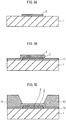
- FIGs. 1A and 1B are each an end elevation showing a manufacturing process of an organic EL display.
- FIG. 1A shows a status in which a first electrode 2, an ITO layer 3, a hole injection layer 4, and a bank 5 are formed on a TFT substrate 1.
- FIG. 1B shows a status in which a light-emitting layer 6, an electron injection layer 7, a second electrode 8, and a passivation layer 9 are formed in addition to the components shown in FIG. 1A .
- a recess 4a is formed in an upper surface of the hole injection layer 4 (see FIG. 1A ) in a process of forming the bank 5.
- the light-emitting layer 6 is formed with the recess 4a formed in the upper surface of the hole injection layer 4 (see FIG. 1B )
- an electric field concentrates in the vicinity of an upper peripheral edge 4c of the recess 4a when the organic EL display emits light.
- localized flow of current can occur in the light-emitting layer 6. This might lead to the occurrence of uneven luminance in a light-emitting surface and reduce a life of the organic EL element due to localized deterioration of the light-emitting layer.
- the inventor arrived at the following technical features through a series of research and studies. That is, by covering the upper peripheral edge of the recess formed in the upper surface of the charge injection transport layer with a part of the bank, concentration of charges in the vicinity of the upper peripheral edge of the recess is suppressed when an organic EL element emits light. As a result, localized flow of current is suppressed.
- One aspect of the present invention is a light-emitter as defined in claim 1.
- the electrical field concentration in the vicinity of the upper peripheral edge of the recess is suppressed when the light-emitter emits light.
- localized flow of current is suppressed in the light-emitting layer. Therefore, an occurrence of uneven luminance in a light-emitting surface is suppressed, and the luminescence property is further improved.
- the charge injection transport layer may be made from a material that is eroded when exposed to a liquid used for forming the bank. With this structure, the recess is formed in a process of forming a bank without adding extra steps.
- the charge injection transport layer may be made from one of a metal oxide, a metal nitride, and a metal oxynitride. In general, these are hydrophilic materials. Therefore, the recess is formed in a washing process with pure water in the process of forming the bank.
- the part of the bank may reach a bottom of the recess, and a side surface of the bank may slope upward from the bottom of the recess to a top of the bank.
- the part of the bank may be out of contact with a bottom of the recess.
- a method for example, of heat-treating a bank material to make it fluid so that the upper peripheral edge of the recess is covered with a part of the bank material.
- the bank may include an insulating material. With this structure, adjacent light-emitting layers are insulated from each other.
- the upper peripheral edge of the recess may be a convex portion composed of (i) a part of the upper surface of the charge injection transport layer in which the recess is not formed and (ii) an inner side surface of the recess.
- Another aspect of the present invention is a light-emitting device comprising a plurality of light-emitters described above.
- Yet another aspect of the present invention is a method of manufacturing a light-emitter as defined in claim 8.
- an organic EL element using an organic EL material as a light-emitting layer is taken as an example of the light-emitter
- an organic EL display is taken as an example of the light-emitting device having a plurality of light-emitters. Note that the drawings are not to scale, so that proportions of members in the drawings are different from actual proportions.
- FIG. 2 is a plan view showing a part of an organic EL display in embodiment of the present invention.
- a organic EL display 100 is a top-emission type organic EL display composed of organic EL elements 10a, 10b, and 10c arranged in a matrix and each provided with a light emitting layer having a color of either red (R), green (G), or blue (B). Each organic EL element functions as a sub-pixel, and three consecutive organic EL elements of colors of RGB function as a pixel as a whole.
- a pixel bank 55 having a lattice shape is adopted.
- Each bank element 55a extending along a Y axis delimits consecutive light-emitting layers 56a1, 56b1, and 56c1 arranged along an X axis as well as consecutive light-emitting layers 56a2, 56b2, and 56c2 arranged along the X axis.
- a bank element 55b extending along the X axis delimits adjacent light-emitting layers 56al and 56a2 arranged along the Y axis, adjacent light-emitting layers 56b1 and 56b2 arranged along the Y axis, and adjacent light-emitting layers 56c1 and 56c2 arranged along the Y axis.
- FIG. 3 is an end elevation schematically showing a cross section of a part of the organic EL display in embodiment of the present invention taken along the line A-A of FIG. 2 .
- FIG. 4 is an enlarged end elevation of a portion B enclosed by an alternate long and short dash line of FIG. 3 .
- the first electrodes (anodes) 2 are formed in a matrix.
- the ITO (indium tin oxide) layer 3 and the hole injection layer 4 are laminated in the stated order. Note that, while the ITO layer 3 is laminated only on the first electrode 2, the hole injection layer 4 is formed not only on the first electrode 2 but also over the substrate 1.
- the bank 5 is formed above a periphery of the first electrode 2 via the hole injection layer 4.
- the light-emitting layer 6 is laminated in an area defined by the bank 5.
- the electron injection layer 7, the second electrode (cathode) 8, and the passivation layer 9 are formed continuously across the consecutive organic EL elements 10a, 10b and 10c, passing over the bank 5.
- the substrate 1 is made from an insulating material such as alkali-free glass, soda glass, nonluminescent glass, phosphate glass, boric-acid glass, quartz, acrylic resin, styrene resin, polycarbonate resin, epoxy resin, polyethylene, polyester, silicon resin, and alumina.
- an insulating material such as alkali-free glass, soda glass, nonluminescent glass, phosphate glass, boric-acid glass, quartz, acrylic resin, styrene resin, polycarbonate resin, epoxy resin, polyethylene, polyester, silicon resin, and alumina.
- the first electrode 2 is made of Ag (silver).
- the first electrode 2 may be made of APC (alloy of silver, palladium and copper), ARA (alloy of silver, rubidium and gold), MoCr (alloy of molybdenum and chrome) or NiCr (alloy of nickel and chrome), for example.
- APC alloy of silver, palladium and copper
- ARA alloy of silver, rubidium and gold
- MoCr alloy of molybdenum and chrome
- NiCr alloy of nickel and chrome
- the ITO layer 3 is interposed between the first electrode 2 and the hole injection layer 4, and has a function of improving the bond between these layers.
- the hole injection layer 4 is made from WOx (tungsten oxide) or MoxWyOz (molybdenum-tungsten oxide). Note that the hole injection layer 4 only has to be made from a metal compound performing a function of injecting holes. Examples of such a metal compound are a metal oxide, a metal nitride, and a metal oxynitride.
- the hole injection layer 4 is made from a specific metal compound, it is easy to inject holes, and electrons contribute to light emission effectively in the light-emitting layer 6. Therefore, favorable luminescence property is obtained.
- the specific metal compound be a transition metal.
- the oxidization number of a transition metal is plural, and therefore the transition metal can have a plurality of levels. As a result, it becomes easy to inject holes, and thus drive voltage is reduced.
- the hole injection layer 4 extends laterally along bottom surfaces 5a and 5b of the bank 5, and has a recess 4a in an upper surface thereof.
- a bottom 4b of the recess 4a is lower than a level 5c of the bottom surface 5a of the bank 5.
- the recess 4a is made up of the bottom 4b and an inner side surface 4d continuing the bottom 4b.
- the depth of the recess 4a is approximately 5 nm to 30 nm.
- An upper peripheral edge 4c of the recess is a convex portion composed of (i) a part of the upper surface of the hole injection layer 4 in which the recess is not formed 4e and (ii) the inner side surface 4d of the recess.
- the upper peripheral edge 4c is covered with a covering part 5d, which is a part of the bank 5.
- the upper peripheral edge 4c of the recess protrudes from the bottom 4b of the recess. Therefore, if the upper peripheral edge 4c is not covered with the covering part 5d made from an insulating material, electric field concentrates in the vicinity of the upper peripheral edge 4c of the recess, and localized flow of current occurs in the light-emitting layer 6. As a result, the uneven luminance occurs in a light-emitting surface and a life of the organic EL element is reduced due to localized deterioration of the light-emitting layer 6. In the present embodiment, however, the above-mentioned problems are prevented, because the upper peripheral edge 4c of the recess is covered with the covering part 5d made from an insulating material. Note that it is desirable that the thickness of the covering part 5d (a shortest distance between the upper peripheral edge 4c of the recess and the light-emitting layer 6) be 2 nm to 5 nm to effectively suppress the electric field concentration.
- the upper peripheral edge 4c of the recess has a right angle.
- the upper peripheral edge 4c of the recess may have a plurality of angles, or may be curved. In such a case, the electrical field concentration is further suppressed.
- the covering part 5d reaches the bottom 4b of the recess 4a, and a side surface of the bank 5 slopes upward from the bottom 4b of the recess to a top of the bank 5.
- the bank 5 partitions the light-emitting layer 6 into sub-pixels.
- the bank 5 is made from an organic material, such as a resin, and has an insulating property. Examples of the organic material are an acrylic resin, a polyimide resin and a novolac-type phenolic resin. It is preferable that the bank 5 be resistant to organic solvent. Furthermore, the bank 5 can be subjected to an etching process, a baking process or the like. Therefore, it is preferable that the bank 5 be made from a highly resistant material so as not to be excessively deformed or degenerated by such processes.
- the light-emitting layer 6 be made from a fluorescent material such as an oxinoid compound, perylene compound, coumarin compound, azacoumarin compound, oxazole compound, oxadiazole compound, perinone compound, pyrrolo-pyrrole compound, naphthalene compound, anthracene compound, fluorene compound, fluoranthene compound, tetracene compound, pyrene compound, coronene compound, quinolone compound and azaquinolone compound, pyrazoline derivative and pyrazolone derivative, rhodamine compound, chrysene compound, phenanthrene compound, cyclopentadiene compound, stilbene compound, diphenylquinone compound, styryl compound, butadiene compound, dicyanomethylene pyran compound, dicyanomethylene thiopyran compound, fluorescein compound, pyrylium compound, thiapyrylium compound, sel
- the electron injection layer 7 has a function of transporting, to the light-emitting layer 6, an electron injected from the second electrode 8. It is preferable that the electron injection layer 7 be made from barium, phthalocyanine, fluorine lithium, or a combination of these materials.
- the second electrode 8 is made of ITO, or IZO (indium zinc oxide), for example. In a case of a top-emission type light-emitter, it is preferable that the second electrode 8 be made of a light-transmissive material.
- the passivation layer 9 has a function of preventing the light-emitting layer 6 and so on from being exposed to moisture and air.
- the passivation layer 9 is made from a material such as SiN (silicon nitride) and SiON (silicon oxynitride).
- a top-emission type light-emitter preferably includes the passivation layer 9 made of a light-transmissive material.
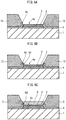
- FIGs. 5A, 5B, 5C , 6A, 6B, 6C , 7A, 7B, and 7C are each a process chart showing a method of manufacturing the organic EL display in embodiment of the present invention.
- a thin Ag film is formed on the substrate 1 using a sputtering method.
- the formed thin Ag film is then patterned using photolithography or the like to form the first electrodes 2 in a matrix.
- the thin Ag film may be formed using a vacuum evaporation method or the like.
- a thin ITO film is formed using the sputtering method or the like.
- the formed thin ITO film is then patterned using the photolithography or the like to form the ITO layer 3.
- a thin WOx film 11 or a thin MoxWyOz film 11 is formed from a composition containing WOx or MoxWyOz using technology such as vacuum evaporation and sputtering.
- a bank material layer 12 is formed on the thin film 11.
- a portion of the bank material layer 12 is removed so that the thin film 11 is partially exposed.
- the bank material layer 12 is formed by application or the like.
- the portion of the bank material layer 12 is removed by forming a resist pattern on the bank material layer 12, and then performing etching.
- the resist pattern is removed by an aqueous or non-aqueous release agent after the etching.
- the remaining portion of the bank material layer 12 is made fluid to some extent by heat treatment so that a bank material extends to cover the upper peripheral edge 4c of the recess.
- the upper peripheral edge 4c of the recess is covered with the covering part 5d in the above-mentioned manner.
- a heat cure can be adopted as the heat treatment, for example.
- the temperature and time for the heat cure may be appropriately determined in consideration of a type of the bank material and a required thickness of the covering part 5d and so on.
- a surface of the remaining portion of the bank material layer 12 is, for example, subjected to treatment using fluorine plasma and the like to provide liquid repellency as necessary, and, as a result, the bank 5 is formed.
- an ink composition including an organic EL material (hereinafter, simply referred to as "ink") is dropped in the area defined by the bank 5 by the inkjet method or the like.
- the ink may be dropped by a dispenser method, a nozzle-coat method, a spin coat method, an intaglio printing, a letter press printing, or the like.
- a thin barium film as the electron injection layer 7 is formed using a vacuum evaporation method or the like.
- a thin ITO film as the second electrode 8 is formed using a sputtering method.
- the passivation layer 9 is further formed.
- the electrical field concentration in the vicinity of the upper peripheral edge 4c of the recess is suppressed because the upper peripheral edge 4c of the recess is covered with the covering part 5d and the light-emitting layer 6 is formed on the covering part 5d.
- the present invention is applicable to an organic EL display and the like.
Landscapes
- Engineering & Computer Science (AREA)
- Physics & Mathematics (AREA)
- Optics & Photonics (AREA)
- Manufacturing & Machinery (AREA)
- Microelectronics & Electronic Packaging (AREA)
- Electroluminescent Light Sources (AREA)
Description
- The present invention relates to a light-emitter, a light-emitting device having the same, and a method of manufacturing the light-emitter.
- In recent years, progress has been made in research and development of an organic electroluminescence element (hereinafter, referred to as an "organic EL element"). The organic EL element is a light-emitter that uses the phenomenon of electroluminescence occurring in organic material. The organic EL element has a structure in which a light-emitting layer is interposed between a first electrode (anode) and a second electrode (cathode). A bank made from an insulating material is formed laterally along the light-emitting layer, and defines a shape of the light-emitting layer. Between the first electrode and the light-emitting layer, a hole injection layer, a hole transport layer, or a hole injection transport layer, for example, is interposed, as necessary. Between the second electrode and the light-emitting layer, an electron injection layer, an electron transport layer, or an electron injection transport layer is interposed, as necessary. Hereinafter, the hole injection layer, the hole transport layer, the hole injection transport layer, the electron injection layer, the electron transport layer, and the electron injection transport layer are collectively referred to as a "charge injection transport layer".
- Although the charge injection transport layer of a conventional organic EL element is formed using a conductive polymer material such as PEDOT (a mixture of polythiophene and polystyrene sulfonate), use of the charge injection transport layer formed using a metal compound such as a transition metal oxide has been proposed (see
Patent Literature 1, for example). The metal compound has a better voltage-current density property than the PEDOT, and is considered to be less likely to deteriorate when high current is applied to increase luminescence intensity. Therefore, the metal compound is expected to be used for the charge injection transport layer.JP 2007 220656 A - Japanese Patent Application Publication No.
2005-203339 - Here, it is also necessary to improve a luminescence property of an organic EL element having the above-mentioned structure in which the metal compound is applied to the charge injection transport.
- The present invention therefore aims to provide a light-emitter having a favorable luminescence property, a light-emitting device having the light-emitter, and a method of manufacturing the light-emitter.
- One aspect of the present invention is a light-emitter as defined in
claim 1. A method of manufacturing a light-emitter is defined inclaim 8. Further advantageous embodiments are defined in the dependent claims. - With the above-mentioned structure, since the upper peripheral edge of the recess formed in the charge injection transport layer is covered with the part of the bank, the electrical field concentration in the vicinity of the upper peripheral edge of the recess is suppressed when the light-emitter emits light. As a result, localized flow of current is suppressed in the light-emitting layer. Therefore, uneven luminance in a light-emitting surface is prevented from occurring, and the luminescence property is further improved.
-
-
FIGs. 1A and 1B each show an end elevation to illustrate a technical problem of the conventional art. -
FIG. 2 is a plan view showing a part of an organic EL display in embodiment of the present invention. -
FIG. 3 is an end elevation schematically showing a cross section of the part of the organic EL display in embodiment of the present invention. -
FIG. 4 is an enlarged end elevation of a portion B enclosed by an alternate long and short dash line ofFIG. 3 . -
FIGs. 5A, 5B, and 5C are each a process chart showing a method of manufacturing the organic EL display in embodiment of the present invention. -
FIGs. 6A, 6B, and 6C are each a process chart showing the method of manufacturing the organic EL display in embodiment of the present invention. -
FIGs. 7A, 7B, and 7C are each a process chart showing the method of manufacturing the organic EL display in embodiment of the present invention. -
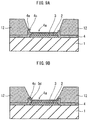
FIG. 8 is an end elevation schematically showing a cross section of a part of an organic EL display in modification of the present invention. -
FIGs. 9A and 9B are each a process chart showing a method of manufacturing the organic EL display in modification of the present invention. -
FIG. 10 is an end elevation schematically showing a cross section of a part of an organic EL display in modification of the present invention. -
FIG. 11 is a plan view showing a part of an organic EL display in modification of the present invention. - Regarding the organic EL element to which the metal compound is applied as described in the section of Background Art, the inventor found, through an intense study, that the uneven luminance can occur in the light-emitting surface and a life of the organic EL element can be reduced due to localized deterioration of the light-emitting layer.
- After further studying these problems, the inventor gained the following knowledge.
-
FIGs. 1A and 1B are each an end elevation showing a manufacturing process of an organic EL display.FIG. 1A shows a status in which afirst electrode 2, anITO layer 3, ahole injection layer 4, and abank 5 are formed on aTFT substrate 1.FIG. 1B shows a status in which a light-emitting layer 6, anelectron injection layer 7, asecond electrode 8, and apassivation layer 9 are formed in addition to the components shown inFIG. 1A . - With the structure in which the metal compound is applied to the charge injection transport layer (the
hole injection layer 4 in this example), arecess 4a is formed in an upper surface of the hole injection layer 4 (seeFIG. 1A ) in a process of forming thebank 5. If the light-emittinglayer 6 is formed with therecess 4a formed in the upper surface of the hole injection layer 4 (seeFIG. 1B ), an electric field concentrates in the vicinity of an upperperipheral edge 4c of therecess 4a when the organic EL display emits light. As a result, localized flow of current can occur in the light-emittinglayer 6. This might lead to the occurrence of uneven luminance in a light-emitting surface and reduce a life of the organic EL element due to localized deterioration of the light-emitting layer. - The above-described problems and knowledge are unique to an organic EL element to which a metal compound is applied, and have technical significance in terms of not having been revealed.
- As described above, the inventor arrived at the following technical features through a series of research and studies. That is, by covering the upper peripheral edge of the recess formed in the upper surface of the charge injection transport layer with a part of the bank, concentration of charges in the vicinity of the upper peripheral edge of the recess is suppressed when an organic EL element emits light. As a result, localized flow of current is suppressed.
- One aspect of the present invention is a light-emitter as defined in
claim 1. - With the above-mentioned structure, since the upper peripheral edge of the recess formed in the charge injection transport layer is covered with the part of the bank, the electrical field concentration in the vicinity of the upper peripheral edge of the recess is suppressed when the light-emitter emits light. As a result, localized flow of current is suppressed in the light-emitting layer. Therefore, an occurrence of uneven luminance in a light-emitting surface is suppressed, and the luminescence property is further improved.
- Also, the charge injection transport layer may be made from a material that is eroded when exposed to a liquid used for forming the bank. With this structure, the recess is formed in a process of forming a bank without adding extra steps.
- Also, the charge injection transport layer may be made from one of a metal oxide, a metal nitride, and a metal oxynitride. In general, these are hydrophilic materials. Therefore, the recess is formed in a washing process with pure water in the process of forming the bank.
- Also, the part of the bank may reach a bottom of the recess, and a side surface of the bank may slope upward from the bottom of the recess to a top of the bank. With this structure, when the light-emitting layer is formed using printing technology such as inkjet technology, ink is distributed to every corner of an area defined by the bank. As a result, formation of a void and the like is suppressed.
- Also, the part of the bank may be out of contact with a bottom of the recess. In order to cover the upper peripheral edge of the recess with the part of the bank, there is a method, for example, of heat-treating a bank material to make it fluid so that the upper peripheral edge of the recess is covered with a part of the bank material. With the above-mentioned structure, the temperature and time of the heat treatment are reduced as it is not necessary to extend the bank material to the bottom of the recess.
- Also, the bank may include an insulating material. With this structure, adjacent light-emitting layers are insulated from each other.
- Also, the upper peripheral edge of the recess may be a convex portion composed of (i) a part of the upper surface of the charge injection transport layer in which the recess is not formed and (ii) an inner side surface of the recess.
- Another aspect of the present invention is a light-emitting device comprising a plurality of light-emitters described above.
- Yet another aspect of the present invention is a method of manufacturing a light-emitter as defined in
claim 8. - The following describes embodiment of the present invention in detail, with reference to the drawings. Here, an organic EL element using an organic EL material as a light-emitting layer is taken as an example of the light-emitter, and an organic EL display is taken as an example of the light-emitting device having a plurality of light-emitters. Note that the drawings are not to scale, so that proportions of members in the drawings are different from actual proportions.
-
FIG. 2 is a plan view showing a part of an organic EL display in embodiment of the present invention. - A
organic EL display 100 is a top-emission type organic EL display composed oforganic EL elements - In an example of
FIG. 2 , apixel bank 55 having a lattice shape is adopted. Eachbank element 55a extending along a Y axis delimits consecutive light-emitting layers 56a1, 56b1, and 56c1 arranged along an X axis as well as consecutive light-emitting layers 56a2, 56b2, and 56c2 arranged along the X axis. - On the other hand, a
bank element 55b extending along the X axis delimits adjacent light-emitting layers 56al and 56a2 arranged along the Y axis, adjacent light-emitting layers 56b1 and 56b2 arranged along the Y axis, and adjacent light-emitting layers 56c1 and 56c2 arranged along the Y axis. -
FIG. 3 is an end elevation schematically showing a cross section of a part of the organic EL display in embodiment of the present invention taken along the line A-A ofFIG. 2 .FIG. 4 is an enlarged end elevation of a portion B enclosed by an alternate long and short dash line ofFIG. 3 . - On the TFT substrate 1 (hereinafter, simply referred to as a "
substrate 1"), the first electrodes (anodes) 2 are formed in a matrix. On thefirst electrode 2, the ITO (indium tin oxide)layer 3 and thehole injection layer 4 are laminated in the stated order. Note that, while theITO layer 3 is laminated only on thefirst electrode 2, thehole injection layer 4 is formed not only on thefirst electrode 2 but also over thesubstrate 1. - The
bank 5 is formed above a periphery of thefirst electrode 2 via thehole injection layer 4. The light-emittinglayer 6 is laminated in an area defined by thebank 5. On the light-emittinglayer 6, theelectron injection layer 7, the second electrode (cathode) 8, and thepassivation layer 9 are formed continuously across the consecutiveorganic EL elements bank 5. - The
substrate 1 is made from an insulating material such as alkali-free glass, soda glass, nonluminescent glass, phosphate glass, boric-acid glass, quartz, acrylic resin, styrene resin, polycarbonate resin, epoxy resin, polyethylene, polyester, silicon resin, and alumina. - The
first electrode 2 is made of Ag (silver). Note that thefirst electrode 2 may be made of APC (alloy of silver, palladium and copper), ARA (alloy of silver, rubidium and gold), MoCr (alloy of molybdenum and chrome) or NiCr (alloy of nickel and chrome), for example. In a case of a top-emission type light-emitter, it is preferable that thefirst electrode 2 be made of a light-reflective material. - The
ITO layer 3 is interposed between thefirst electrode 2 and thehole injection layer 4, and has a function of improving the bond between these layers. - The
hole injection layer 4 is made from WOx (tungsten oxide) or MoxWyOz (molybdenum-tungsten oxide). Note that thehole injection layer 4 only has to be made from a metal compound performing a function of injecting holes. Examples of such a metal compound are a metal oxide, a metal nitride, and a metal oxynitride. - When the
hole injection layer 4 is made from a specific metal compound, it is easy to inject holes, and electrons contribute to light emission effectively in the light-emittinglayer 6. Therefore, favorable luminescence property is obtained. It is preferable that the specific metal compound be a transition metal. The oxidization number of a transition metal is plural, and therefore the transition metal can have a plurality of levels. As a result, it becomes easy to inject holes, and thus drive voltage is reduced. - As shown in
FIG. 4 , thehole injection layer 4 extends laterally alongbottom surfaces bank 5, and has arecess 4a in an upper surface thereof. A bottom 4b of therecess 4a is lower than alevel 5c of thebottom surface 5a of thebank 5. Therecess 4a is made up of the bottom 4b and aninner side surface 4d continuing the bottom 4b. The depth of therecess 4a is approximately 5 nm to 30 nm. An upperperipheral edge 4c of the recess is a convex portion composed of (i) a part of the upper surface of thehole injection layer 4 in which the recess is not formed 4e and (ii) theinner side surface 4d of the recess. The upperperipheral edge 4c is covered with acovering part 5d, which is a part of thebank 5. - The upper
peripheral edge 4c of the recess protrudes from the bottom 4b of the recess. Therefore, if the upperperipheral edge 4c is not covered with the coveringpart 5d made from an insulating material, electric field concentrates in the vicinity of the upperperipheral edge 4c of the recess, and localized flow of current occurs in the light-emittinglayer 6. As a result, the uneven luminance occurs in a light-emitting surface and a life of the organic EL element is reduced due to localized deterioration of the light-emittinglayer 6. In the present embodiment, however, the above-mentioned problems are prevented, because the upperperipheral edge 4c of the recess is covered with the coveringpart 5d made from an insulating material. Note that it is desirable that the thickness of thecovering part 5d (a shortest distance between the upperperipheral edge 4c of the recess and the light-emitting layer 6) be 2 nm to 5 nm to effectively suppress the electric field concentration. - In an example of
FIG. 4 , the upperperipheral edge 4c of the recess has a right angle. The upperperipheral edge 4c of the recess, however, may have a plurality of angles, or may be curved. In such a case, the electrical field concentration is further suppressed. - In the present embodiment, the covering
part 5d reaches the bottom 4b of therecess 4a, and a side surface of thebank 5 slopes upward from the bottom 4b of the recess to a top of thebank 5. With this structure, when the light-emittinglayer 6 is formed using printing technology such as inkjet technology, ink is distributed to every corner of an area defined by the bank. As a result, formation of a void and the like is suppressed. - The
bank 5 partitions the light-emittinglayer 6 into sub-pixels. Thebank 5 is made from an organic material, such as a resin, and has an insulating property. Examples of the organic material are an acrylic resin, a polyimide resin and a novolac-type phenolic resin. It is preferable that thebank 5 be resistant to organic solvent. Furthermore, thebank 5 can be subjected to an etching process, a baking process or the like. Therefore, it is preferable that thebank 5 be made from a highly resistant material so as not to be excessively deformed or degenerated by such processes. - It is preferable that the light-emitting
layer 6 be made from a fluorescent material such as an oxinoid compound, perylene compound, coumarin compound, azacoumarin compound, oxazole compound, oxadiazole compound, perinone compound, pyrrolo-pyrrole compound, naphthalene compound, anthracene compound, fluorene compound, fluoranthene compound, tetracene compound, pyrene compound, coronene compound, quinolone compound and azaquinolone compound, pyrazoline derivative and pyrazolone derivative, rhodamine compound, chrysene compound, phenanthrene compound, cyclopentadiene compound, stilbene compound, diphenylquinone compound, styryl compound, butadiene compound, dicyanomethylene pyran compound, dicyanomethylene thiopyran compound, fluorescein compound, pyrylium compound, thiapyrylium compound, selenapyrylium compound, telluropyrylium compound, aromatic aldadiene compound, oligophenylene compound, thioxanthene compound, anthracene compound, cyanine compound, acridine compound, metal complex of a 8-hydroxyquinoline compound, metal complex of a 2-bipyridine compound, complex of a Schiff base and a group three metal, metal complex of oxine, rare earth metal complex, etc., as recited in Japanese Patent Application Publication No.5-163488 - The
electron injection layer 7 has a function of transporting, to the light-emittinglayer 6, an electron injected from thesecond electrode 8. It is preferable that theelectron injection layer 7 be made from barium, phthalocyanine, fluorine lithium, or a combination of these materials. - The
second electrode 8 is made of ITO, or IZO (indium zinc oxide), for example. In a case of a top-emission type light-emitter, it is preferable that thesecond electrode 8 be made of a light-transmissive material. - The
passivation layer 9 has a function of preventing the light-emittinglayer 6 and so on from being exposed to moisture and air. Thepassivation layer 9 is made from a material such as SiN (silicon nitride) and SiON (silicon oxynitride). A top-emission type light-emitter preferably includes thepassivation layer 9 made of a light-transmissive material. -
FIGs. 5A, 5B, 5C ,6A, 6B, 6C ,7A, 7B, and 7C are each a process chart showing a method of manufacturing the organic EL display in embodiment of the present invention. - At first, as shown in
FIG. 5A , a thin Ag film is formed on thesubstrate 1 using a sputtering method. The formed thin Ag film is then patterned using photolithography or the like to form thefirst electrodes 2 in a matrix. Note that the thin Ag film may be formed using a vacuum evaporation method or the like. - Next, as shown in
FIG. 5B , a thin ITO film is formed using the sputtering method or the like. The formed thin ITO film is then patterned using the photolithography or the like to form theITO layer 3. Then, athin WOx film 11 or athin MoxWyOz film 11 is formed from a composition containing WOx or MoxWyOz using technology such as vacuum evaporation and sputtering. - Next, as shown in
FIG. 5C , abank material layer 12 is formed on thethin film 11. A portion of thebank material layer 12 is removed so that thethin film 11 is partially exposed. Thebank material layer 12 is formed by application or the like. The portion of thebank material layer 12 is removed by forming a resist pattern on thebank material layer 12, and then performing etching. The resist pattern is removed by an aqueous or non-aqueous release agent after the etching. - Next, residues remaining after the etching are removed by being washed with pure water. Here, WOx or MoxWyOz, which is a material for the
thin film 11, is soluble in pure water. Therefore, as shown inFIG. 6A , an exposed portion of thethin film 11 is eroded, and a recess is formed. As a result, thehole injection layer 4 having therecess 4a is formed. - Next, as shown in
FIG. 6B , the remaining portion of thebank material layer 12 is made fluid to some extent by heat treatment so that a bank material extends to cover the upperperipheral edge 4c of the recess. The upperperipheral edge 4c of the recess is covered with the coveringpart 5d in the above-mentioned manner. A heat cure can be adopted as the heat treatment, for example. The temperature and time for the heat cure may be appropriately determined in consideration of a type of the bank material and a required thickness of thecovering part 5d and so on. After that, a surface of the remaining portion of thebank material layer 12 is, for example, subjected to treatment using fluorine plasma and the like to provide liquid repellency as necessary, and, as a result, thebank 5 is formed. - Subsequently, as shown in
FIG. 6C , an ink composition including an organic EL material (hereinafter, simply referred to as "ink") is dropped in the area defined by thebank 5 by the inkjet method or the like. By drying the ink, the light-emittinglayer 6 is formed. Note that the ink may be dropped by a dispenser method, a nozzle-coat method, a spin coat method, an intaglio printing, a letter press printing, or the like. - Next, as shown in
FIG. 7A , a thin barium film as theelectron injection layer 7 is formed using a vacuum evaporation method or the like. Then, as shown inFIG. 7B , a thin ITO film as thesecond electrode 8 is formed using a sputtering method. As shown inFIG. 7C , thepassivation layer 9 is further formed. - With the above-mentioned manufacturing method, even when the
recess 4a is formed in an exposed portion of thehole injection layer 4 during manufacturing, the electrical field concentration in the vicinity of the upperperipheral edge 4c of the recess is suppressed because the upperperipheral edge 4c of the recess is covered with the coveringpart 5d and the light-emittinglayer 6 is formed on thecovering part 5d. - Although having been explained based on the above embodiment, the present invention is not limited to the above embodiment. For example, the following modifications can also be implemented.
- (1) In the above embodiment, WOx or MoxWyOz is used as a material for the
hole injection layer 4. In general, however, a metal oxide, a metal nitride, and a metal oxynitride are likely to be eroded by pure water. Therefore, even when a metal other than Mo (molybdenum) and W (tungsten) is used as a material for thehole injection layer 4, a similar effect is obtained by applying the present embodiment. - (2) In the above embodiment, the recess is formed by the hole injection layer being eroded by pure water during washing. However, an effect of suppressing the electrical field concentration in the vicinity of the upper peripheral edge of the recess is obtained even when the recess is formed in another manner, by applying the present invention. For example, the recess may be formed by the hole injection layer being eroded by etching solution during etching, or by the hole injection layer being eroded by a release agent during removal of the resist pattern. As described above, the present invention is effective in a case where the hole injection layer is made from a material that is eroded when exposed to a liquid used for forming the bank, in particular, the hole injection layer is made from a material that is eroded when exposed to a liquid used while the hole injection layer is partially exposed.
- (3) In the above embodiment, the covering part extending from the bank reaches the bottom 4b of the recess beyond the upper
peripheral edge 4c of the recess. However, the present invention is not limited to the above as long as at least the upperperipheral edge 4c of the recess is covered. For example, as shown inFIG. 8 , the coveringpart 5d may be out of contact with the bottom 4b of the recess. When the structure shown inFIG. 8 is adopted, the temperature and time of the heat treatment are reduced, as it is not necessary to extend the bank material to the bottom of the recess.
In the above embodiment, therecess 4a is formed in thehole injection layer 4 by washing after etching in the process of forming the bank. In the present invention, however, mask pattering or the like may be used as a method of forming the recess. - (4) In
FIG. 6A , although a lower end of the slope of thebank material 12 coincides with the upperperipheral edge 4c of the recess, the structure of thebank material 12 is not limited to this. Depending on the bank material, the part of the upper surface of thehole injection layer 4 in which the recess is not formed 4e may be partially exposed by the slope of thebank material 12 being set back, as shown inFIG. 9A . In such a case, by appropriately heat treating thebank material 12, the upperperipheral edge 4c of the recess is covered with a part of the bank material (seeFIG. 9B ). - (5) In the above embodiment, as the charge injection transport layer, only the
hole injection layer 4 is interposed between the first electrode and the light-emitting layer. However, the present invention is not limited to the above. For example, as shown inFIG. 10 , ahole transport layer 13 may be formed on thehole injection layer 4, and these layers may be interposed as the charge injection transport layer. In this case, the recess is formed in an upper surface of thehole transport layer 13, and an upper peripheral edge of the recess formed in thehole transport layer 13 is covered with the covering part. - (6) In the above embodiment, since the
first electrode 2 is formed from the thin Ag film, theITO layer 3 is formed on thefirst electrode 2. When thefirst electrode 2 is formed from an Al-based material, it is possible to adopt a single layer structure of the anode without forming theITO layer 3. - (7) In the above embodiment, although the organic EL display is taken as an example of the light-emitting device having a plurality of light-emitters, the present invention is not limited to this. The present invention may be applied to a luminaire and the like.
- (8) In the above embodiment, although the so-called pixel bank (a bank having a lattice shape) is adopted, the present invention is not limited to this. For example, a line bank (banks arranged in lines) may be adopted. In an example of
FIG. 11 , theline bank 65 is adopted. Theline bank 65 delimits consecutive light-emittinglayers 66a, 66b, and 66c arranged along the X axis. Note that when theline bank 65 is adopted as shown inFIG. 11 , adjacent light-emitting layers arranged along the Y axis are not defined by the bank element. However, by appropriately determining a driving method, a size of the anode, an interval between the anodes and so on, the adjacent light-emitting layers emit light without influencing each other. - (9) In the above embodiment, although a top-emission type light-emitter is adopted, the light-emitter of the present invention is not limited to the top-emission type light-emitter. A bottom-emission type light-emitter may be adopted.
- (10) In the above embodiment, although only the electron injection layer is interposed between the light-emitting layer and the second electrode, the electron transport layer may be interposed in addition to the electron injection layer.
- The present invention is applicable to an organic EL display and the like.
-
- 1
- TFT substrate
- 2
- first electrode
- 3
- ITO layer
- 4
- hole injection layer
- 4a
- recess
- 4b
- bottom of recess
- 4c
- upper peripheral edge of recess
- 4d
- inner side surface of recess
- 4e
- part of upper surface of hole injection layer in which recess is not formed
- 5
- bank
- 5a, 5b
- bottom su rface of bank
- 5c
- level of bottom surface of bank
- 5d
- covering part
- 6
- light-emitting layer
- 7
- electron injection layer
- 8
- second electrode
- 9
- passivation layer
- 10a, 10b, 10c
- organic EL element
- 11
- thin film
- 12
- bank material layer
- 13
- hole transport layer
- 55
- pixel bank
- 55a
- bank element
- 55b
- bank element
- 56a1, 56a2, 56b1, 56b2, 56c1, 56c2
- light-emitting layer
- 65
- line bank
- 66a, 66b, 66c
- light-emitting layer
- 100
- organic EL display
Claims (8)
- A light-emitter comprising:a first electrode (2);a laminate that is disposed on the first electrode (2) and includes a charge injection transport layer (4) and a light-emitting layer (6);a second electrode (8) that is disposed on the laminate; anda bank (5) that defines an area in which the light-emitting layer (6) is to be formed, whereinin the area defined by the bank (5), the charge injection transport layer (4) has a recess (4a) in an upper surface thereof, andan upper peripheral edge (4c) of the recess (4a) is covered with a part (5d) of the bank (5),characterized in thatthe charge injection transport layer (4) extends laterally along a bottom surface (5a, 5b) of the bank (5),the light-emitting layer (6) is an organic EL layer,the charge injection transport layer (4) comprises a metal compound, andthe upper peripheral edge (4c) of the recess (4a) is covered by the bank (5) such that a direct contact between the upper peripheral edge (4c) and the light emitting layer (6) is prevented by an intervening part of the bank (5).
- The light-emitter of Claim 1, wherein the charge injection transport layer (4) is made from one of a metal oxide, a metal nitride, and a metal oxynitride.
- The light-emitter of Claim 1, wherein
the part (5d) of the bank (5) reaches a bottom (4b) of the recess (4a), and a side surface of the bank (5) slopes upward from the bottom (4b) of the recess (4a) to a top of the bank (5). - The light-emitter of Claim 1, wherein the part (5d) of the bank (5) is out of contact with a bottom (4b) of the recess (4a).
- The light-emitter of Claim 1, wherein the bank (5) includes an insulating material.
- The light-emitter of Claim 1, wherein the upper peripheral edge (4c) of the recess (4a) is a convex portion composed of (i) a part (4e) of the upper surface of the charge injection transport layer (4) in which the recess is not formed and (ii) an inner side surface (4d) of the recess.
- A light-emitting device comprising a plurality of light-emitters that are each the light-emitter of any one of Claims 1 to 6.
- A method of manufacturing a light-emitter including a first electrode (2), a laminate that is disposed on the first electrode (2) and includes a charge injection transport layer (4) and a light-emitting layer (6), a second electrode (8) that is disposed on the laminate, and a bank (5) that defines an area in which the light-emitting layer (6) is to be formed, the method comprising the steps of:forming the charge injection transport layer (4);forming a bank material layer (12) for forming the bank (5) on the charge injection transport layer (4);removing a portion of the bank material layer (12) to partially expose the charge injection transport layer (4);heat-treating a remaining portion of the bank material layer (12); andforming the light-emitting layer (6) on an exposed surface of the charge injection transport layer (4) after the heat treatment, whereinthe charge injection transport layer (4) is made from a material that is eroded when exposed to a liquid used while the charge injection transport layer (4) is partially exposed,the charge injection transport layer (4) has a recess (4a) in the exposed surface thereof so that a bottom (4b) of the recess (4a) is lower than a bottom surface of the remaining portion of the bank material layer (12), the recess (4a) being formed by the exposed surface being eroded by the liquid, andin the heat-treating step, the remaining portion of the bank material layer (12) is made fluid so that the bank material layer (12) extends to cover an upper peripheral edge (4c) of the recess (4a),the charge injection transport layer (4) extends laterally along a bottom surface (5a, 5b) of the bank (5),the light-emitting layer (6) is an organic EL layer,the charge injection transport layer (4) comprises a metal compound, andthe upper peripheral edge (4c) of the recess (4a) is covered by the bank (5) such that a direct contact between the upper peripheral edge (4c) and the light emitting layer (6) is prevented by an intervening part of the bank (5).
Applications Claiming Priority (2)
| Application Number | Priority Date | Filing Date | Title |
|---|---|---|---|
| JP2009028970 | 2009-02-10 | ||
| PCT/JP2010/000782 WO2010092796A1 (en) | 2009-02-10 | 2010-02-09 | Light-emitting element, light-emitting device comprising light-emitting element, and method for manufacturing light-emitting element |
Publications (3)
| Publication Number | Publication Date |
|---|---|
| EP2398084A1 EP2398084A1 (en) | 2011-12-21 |
| EP2398084A4 EP2398084A4 (en) | 2013-03-27 |
| EP2398084B1 true EP2398084B1 (en) | 2018-06-06 |
Family
ID=42561646
Family Applications (1)
| Application Number | Title | Priority Date | Filing Date |
|---|---|---|---|
| EP10741076.3A Active EP2398084B1 (en) | 2009-02-10 | 2010-02-09 | Light-emitting element, light-emitting device comprising light-emitting element, and method for manufacturing light-emitting element |
Country Status (6)
| Country | Link |
|---|---|
| US (1) | US8866160B2 (en) |
| EP (1) | EP2398084B1 (en) |
| JP (1) | JP5357194B2 (en) |
| KR (1) | KR20110126594A (en) |
| CN (1) | CN102272970B (en) |
| WO (1) | WO2010092796A1 (en) |
Families Citing this family (33)
| Publication number | Priority date | Publication date | Assignee | Title |
|---|---|---|---|---|
| JP5357194B2 (en) | 2009-02-10 | 2013-12-04 | パナソニック株式会社 | LIGHT EMITTING ELEMENT, LIGHT EMITTING DEVICE HAVING LIGHT EMITTING ELEMENT, AND METHOD FOR MANUFACTURING LIGHT EMITTING ELEMENT |
| WO2010092797A1 (en) * | 2009-02-10 | 2010-08-19 | パナソニック株式会社 | Light-emitting element, display device, and method for manufacturing light-emitting element |
| CN102308671B (en) | 2009-02-10 | 2015-01-21 | 松下电器产业株式会社 | Method for manufacturing light-emitting element, light-emitting element, method for manufacturing light-emitting device, and light-emitting device |
| JP5437736B2 (en) | 2009-08-19 | 2014-03-12 | パナソニック株式会社 | Organic EL device |
| WO2011161727A1 (en) | 2010-06-24 | 2011-12-29 | パナソニック株式会社 | Method for producing organic el element, display device, light-emitting device, and ultraviolet irradiation device |
| CN102473847B (en) | 2010-06-24 | 2015-01-14 | 松下电器产业株式会社 | Organic el element, display apparatus, and light-emitting apparatus |
| JP5624141B2 (en) | 2010-07-30 | 2014-11-12 | パナソニック株式会社 | Organic EL device |
| CN103053042B (en) | 2010-08-06 | 2016-02-24 | 株式会社日本有机雷特显示器 | Organic EL element and manufacture method thereof |
| JP5677433B2 (en) | 2010-08-06 | 2015-02-25 | パナソニック株式会社 | ORGANIC EL ELEMENT, DISPLAY DEVICE AND LIGHT EMITTING DEVICE |
| JP5677436B2 (en) | 2010-08-06 | 2015-02-25 | パナソニック株式会社 | Organic EL device |
| WO2012017496A1 (en) | 2010-08-06 | 2012-02-09 | パナソニック株式会社 | Light emitting device, light emitting apparatus provided with a light emitting device, and method of manufacturing a light emitting device |
| JP5574456B2 (en) * | 2010-08-06 | 2014-08-20 | パナソニック株式会社 | LIGHT EMITTING ELEMENT, MANUFACTURING METHOD THEREOF, AND LIGHT EMITTING DEVICE |
| WO2012017486A1 (en) | 2010-08-06 | 2012-02-09 | パナソニック株式会社 | Method for producing light-emitting elements |
| JP5612692B2 (en) | 2010-08-06 | 2014-10-22 | パナソニック株式会社 | Organic EL device and method for manufacturing the same |
| WO2012017485A1 (en) | 2010-08-06 | 2012-02-09 | パナソニック株式会社 | Organic el element, display device, and light-emitting device |
| CN103038908B (en) | 2010-08-06 | 2016-01-06 | 株式会社日本有机雷特显示器 | Light-emitting component, possess the light-emitting device of light-emitting component and the manufacture method of light-emitting component |
| WO2012017489A1 (en) | 2010-08-06 | 2012-02-09 | パナソニック株式会社 | Organic el element, display device, and light-emitting device |
| JP5658256B2 (en) | 2010-08-06 | 2015-01-21 | パナソニック株式会社 | LIGHT EMITTING ELEMENT, MANUFACTURING METHOD THEREOF, AND LIGHT EMITTING DEVICE |
| WO2012017487A1 (en) | 2010-08-06 | 2012-02-09 | パナソニック株式会社 | Light-emitting element, display device, and method for producing light-emitting element |
| WO2012017495A1 (en) * | 2010-08-06 | 2012-02-09 | パナソニック株式会社 | Organic el element and production method for same |
| WO2012017503A1 (en) | 2010-08-06 | 2012-02-09 | パナソニック株式会社 | Organic electroluminescence element |
| JP5677434B2 (en) | 2010-08-06 | 2015-02-25 | パナソニック株式会社 | Organic EL device |
| WO2012098587A1 (en) | 2011-01-21 | 2012-07-26 | パナソニック株式会社 | Organic el element |
| JP5884224B2 (en) | 2011-02-23 | 2016-03-15 | 株式会社Joled | Organic EL display panel and organic EL display device |
| WO2012114403A1 (en) | 2011-02-25 | 2012-08-30 | パナソニック株式会社 | Organic electroluminescence display panel and organic electroluminescence display device |
| CN102884650A (en) | 2011-05-11 | 2013-01-16 | 松下电器产业株式会社 | Organic el display panel and organic el display device |
| WO2012161004A1 (en) * | 2011-05-20 | 2012-11-29 | パナソニック株式会社 | Organic electroluminescence element |
| JP6111484B2 (en) * | 2012-04-18 | 2017-04-12 | 株式会社Joled | Organic EL device |
| WO2013179362A1 (en) | 2012-06-01 | 2013-12-05 | パナソニック株式会社 | Organic light emitting element, organic el display panel, organic el display device, coated device, and method for manufacturing these |
| CN107393939B (en) * | 2017-08-30 | 2020-04-17 | 京东方科技集团股份有限公司 | Pixel defining layer and manufacturing method thereof, display panel and manufacturing method thereof, and display device |
| KR20210034809A (en) | 2019-09-23 | 2021-03-31 | 엘지디스플레이 주식회사 | Display device and method for manufacturing the same |
| CN112133734B (en) * | 2020-09-29 | 2022-08-30 | 湖北长江新型显示产业创新中心有限公司 | Display panel and display device |
| KR20230102192A (en) * | 2021-12-30 | 2023-07-07 | 엘지디스플레이 주식회사 | Display device |
Family Cites Families (111)
| Publication number | Priority date | Publication date | Assignee | Title |
|---|---|---|---|---|
| US5443922A (en) | 1991-11-07 | 1995-08-22 | Konica Corporation | Organic thin film electroluminescence element |
| JPH05163488A (en) | 1991-12-17 | 1993-06-29 | Konica Corp | Electroluminescent element of organic thin film |
| US5294869A (en) | 1991-12-30 | 1994-03-15 | Eastman Kodak Company | Organic electroluminescent multicolor image display device |
| US5688551A (en) | 1995-11-13 | 1997-11-18 | Eastman Kodak Company | Method of forming an organic electroluminescent display panel |
| JPH10162959A (en) | 1996-11-29 | 1998-06-19 | Idemitsu Kosan Co Ltd | Organic electro-luminescence element |
| EP1119221B1 (en) | 1996-11-29 | 2004-03-03 | Idemitsu Kosan Company Limited | Organic electroluminescent device |
| JP3782245B2 (en) | 1998-10-28 | 2006-06-07 | Tdk株式会社 | Manufacturing apparatus and manufacturing method of organic EL display device |
| US6309801B1 (en) | 1998-11-18 | 2001-10-30 | U.S. Philips Corporation | Method of manufacturing an electronic device comprising two layers of organic-containing material |
| JP4198253B2 (en) | 1999-02-02 | 2008-12-17 | 出光興産株式会社 | Organic electroluminescence device and method for producing the same |
| JP2002075661A (en) | 2000-08-31 | 2002-03-15 | Fujitsu Ltd | Organic el element and organic el display |
| US7153592B2 (en) | 2000-08-31 | 2006-12-26 | Fujitsu Limited | Organic EL element and method of manufacturing the same, organic EL display device using the element, organic EL material, and surface emission device and liquid crystal display device using the material |
| JP2002318556A (en) | 2001-04-20 | 2002-10-31 | Toshiba Corp | Active matrix type planar display device and manufacturing method therefor |
| TWI257496B (en) | 2001-04-20 | 2006-07-01 | Toshiba Corp | Display device and method of manufacturing the same |
| US8058797B2 (en) | 2001-05-18 | 2011-11-15 | Cambridge University Technical Services Limited | Electroluminescent device |
| JP2003007460A (en) | 2001-06-22 | 2003-01-10 | Sony Corp | Method for manufacturing display equipment, and display equipment |
| JP3823916B2 (en) | 2001-12-18 | 2006-09-20 | セイコーエプソン株式会社 | Display device, electronic apparatus, and display device manufacturing method |
| JP2003264083A (en) | 2002-03-08 | 2003-09-19 | Sharp Corp | Organic led element and production process thereof |
| US7086917B2 (en) | 2002-08-12 | 2006-08-08 | National Research Council Of Canada | Photoresist mask/smoothing layer ensuring the field homogeneity and better step-coverage in OLED displays |
| JP4165173B2 (en) | 2002-10-15 | 2008-10-15 | 株式会社デンソー | Manufacturing method of organic EL element |
| JP2004228355A (en) | 2003-01-23 | 2004-08-12 | Seiko Epson Corp | Insulating film substrate, method and apparatus for manufacturing the same, electro-optical device and method for manufacturing the same |
| JP2004234901A (en) * | 2003-01-28 | 2004-08-19 | Seiko Epson Corp | Display substrate, organic el display device, manufacturing method of display substrate and electronic apparatus |
| EP1629544B1 (en) | 2003-05-12 | 2008-11-19 | Cambridge Enterprise Limited | Polymer transistor |
| ATE401672T1 (en) | 2003-05-12 | 2008-08-15 | Cambridge Entpr Ltd | PREPARATION OF A POLYMERIC DEVICE |
| JP2005012173A (en) | 2003-05-28 | 2005-01-13 | Seiko Epson Corp | Film pattern forming method, device and its manufacturing method, electro-optical device, and electronic apparatus |
| JP2004363170A (en) | 2003-06-02 | 2004-12-24 | Seiko Epson Corp | Method of forming conductive pattern, electrooptic device, method of manufacturing the same, and electronic equipment |
| US7492090B2 (en) * | 2003-09-19 | 2009-02-17 | Semiconductor Energy Laboratory Co., Ltd. | Display device and method for manufacturing the same |
| US7230374B2 (en) | 2003-09-22 | 2007-06-12 | Samsung Sdi Co., Ltd. | Full color organic light-emitting device having color modulation layer |
| US20060139342A1 (en) * | 2004-12-29 | 2006-06-29 | Gang Yu | Electronic devices and processes for forming electronic devices |
| US20090160325A1 (en) | 2003-12-16 | 2009-06-25 | Panasonic Corporation | Organic electroluminescent device and method for manufacturing the same |
| ATE433200T1 (en) | 2003-12-16 | 2009-06-15 | Panasonic Corp | ORGANIC ELECTROLUMINENCE COMPONENT AND PRODUCTION METHOD THEREOF |
| JP2005203340A (en) | 2003-12-16 | 2005-07-28 | Matsushita Electric Ind Co Ltd | Organic electroluminescent element |
| JP2005203339A (en) | 2003-12-16 | 2005-07-28 | Matsushita Electric Ind Co Ltd | Organic electroluminescent element and its manufacturing method |
| JP4857521B2 (en) | 2004-01-09 | 2012-01-18 | セイコーエプソン株式会社 | Electro-optical device manufacturing method, electro-optical device, and electronic apparatus |
| JP4002949B2 (en) | 2004-03-17 | 2007-11-07 | 独立行政法人科学技術振興機構 | Double-sided organic EL panel |
| JP2005268099A (en) | 2004-03-19 | 2005-09-29 | Mitsubishi Electric Corp | Organic el display panel, organic el display device, and method of manufacturing organic el display panel |
| JP4645064B2 (en) | 2004-05-19 | 2011-03-09 | セイコーエプソン株式会社 | Manufacturing method of electro-optical device |
| JP4161956B2 (en) | 2004-05-27 | 2008-10-08 | セイコーエプソン株式会社 | Color filter substrate manufacturing method, electro-optical device manufacturing method, electro-optical device, and electronic apparatus |
| US7211456B2 (en) | 2004-07-09 | 2007-05-01 | Au Optronics Corporation | Method for electro-luminescent display fabrication |
| JP2006185869A (en) | 2004-12-28 | 2006-07-13 | Asahi Glass Co Ltd | Organic electroluminescent element and method of manufacturing the same |
| DE102005007540A1 (en) * | 2005-02-18 | 2006-08-31 | Robert Bosch Gmbh | Micromechanical membrane sensor with double membrane |
| JP2006253443A (en) | 2005-03-11 | 2006-09-21 | Seiko Epson Corp | Organic el device, its manufacturing method, and electronic apparatus |
| JP2006294261A (en) | 2005-04-05 | 2006-10-26 | Fuji Electric Holdings Co Ltd | Organic el light-emitting element and its manufacturing method |
| TWI307612B (en) | 2005-04-27 | 2009-03-11 | Sony Corp | Transfer method and transfer apparatus |
| JP2006344459A (en) | 2005-06-08 | 2006-12-21 | Sony Corp | Transfer method and transfer device |
| US7994711B2 (en) | 2005-08-08 | 2011-08-09 | Semiconductor Energy Laboratory Co., Ltd. | Light emitting device and manufacturing method thereof |
| JP2007073499A (en) | 2005-08-08 | 2007-03-22 | Semiconductor Energy Lab Co Ltd | Light-emitting device and its manufacturing method |
| GB0517195D0 (en) | 2005-08-23 | 2005-09-28 | Cambridge Display Tech Ltd | Molecular electronic device structures and fabrication methods |
| US8080935B2 (en) * | 2005-09-29 | 2011-12-20 | Panasonic Corporation | Organic EL display and method for manufacturing same |
| JP2007095606A (en) | 2005-09-30 | 2007-04-12 | Seiko Epson Corp | Organic el device, its manufacturing method, and electronics device |
| JP2007150258A (en) * | 2005-10-27 | 2007-06-14 | Seiko Epson Corp | Pattern forming method, film structure, electro-optic device, and electronic apparatus |
| JP4318689B2 (en) | 2005-12-09 | 2009-08-26 | 出光興産株式会社 | N-type inorganic semiconductor, n-type inorganic semiconductor thin film, and manufacturing method thereof |
| JP5256605B2 (en) * | 2006-01-18 | 2013-08-07 | 凸版印刷株式会社 | Method for manufacturing organic electroluminescence element |
| JP2007214066A (en) | 2006-02-13 | 2007-08-23 | Seiko Epson Corp | Manufacturing method of organic electroluminescent device |
| JP2007288071A (en) | 2006-04-19 | 2007-11-01 | Matsushita Electric Ind Co Ltd | Organic electroluminescent element, method of manufacturing the same, and display device and exposure device using the same |
| JP2007288074A (en) | 2006-04-19 | 2007-11-01 | Matsushita Electric Ind Co Ltd | Organic electroluminescence element and manufacturing method thereof |
| US20070241665A1 (en) | 2006-04-12 | 2007-10-18 | Matsushita Electric Industrial Co., Ltd. | Organic electroluminescent element, and manufacturing method thereof, as well as display device and exposure apparatus using the same |
| JP2007287353A (en) | 2006-04-12 | 2007-11-01 | Matsushita Electric Ind Co Ltd | Manufacturing method of organic electroluminescent element and organic electroluminescent element formed using it |
| US20070290604A1 (en) | 2006-06-16 | 2007-12-20 | Matsushita Electric Industrial Co., Ltd. | Organic electroluminescent device and method of producing the same |
| JP2008041747A (en) | 2006-08-02 | 2008-02-21 | Matsushita Electric Ind Co Ltd | Organic electroluminescent light-emitting apparatus and manufacturing method thereof |
| JP4915650B2 (en) | 2006-08-25 | 2012-04-11 | パナソニック株式会社 | Organic electroluminescence device |
| JP2008091072A (en) | 2006-09-29 | 2008-04-17 | Seiko Epson Corp | Electro-optical device and its manufacturing method |
| JP4915913B2 (en) | 2006-11-13 | 2012-04-11 | パナソニック株式会社 | Organic electroluminescence device |
| JP2008140724A (en) | 2006-12-05 | 2008-06-19 | Toppan Printing Co Ltd | Organic el element and manufacturing method of same |
| WO2008075615A1 (en) | 2006-12-21 | 2008-06-26 | Semiconductor Energy Laboratory Co., Ltd. | Light-emitting element and light-emitting device |
| JP4998710B2 (en) * | 2007-03-06 | 2012-08-15 | カシオ計算機株式会社 | Manufacturing method of display device |
| JP5326289B2 (en) | 2007-03-23 | 2013-10-30 | 凸版印刷株式会社 | ORGANIC EL ELEMENT AND DISPLAY DEVICE INCLUDING THE SAME |
| JP5333211B2 (en) | 2007-03-29 | 2013-11-06 | 大日本印刷株式会社 | Organic electroluminescence device and method for manufacturing the same |
| JP2009004347A (en) | 2007-05-18 | 2009-01-08 | Toppan Printing Co Ltd | Manufacturing method for organic el display element and organic el display element |
| KR100919352B1 (en) * | 2007-05-30 | 2009-09-25 | 파나소닉 주식회사 | Organic Electroluminescence Display Panel and Manufacturing Method Thereof |
| EP2141964B1 (en) * | 2007-05-31 | 2011-09-07 | Panasonic Corporation | Organic EL element and manufacturing method thereof |
| WO2009017026A1 (en) | 2007-07-31 | 2009-02-05 | Sumitomo Chemical Company, Limited | Organic electroluminescence element and method for manufacturing the same |
| JP5001745B2 (en) | 2007-08-10 | 2012-08-15 | 住友化学株式会社 | Organic electroluminescence device and manufacturing method |
| JP2009048960A (en) | 2007-08-23 | 2009-03-05 | Canon Inc | Electrode cleaning treatment method |
| JP2009058897A (en) | 2007-09-03 | 2009-03-19 | Hitachi Displays Ltd | Display device |
| US8083956B2 (en) * | 2007-10-11 | 2011-12-27 | Semiconductor Energy Laboratory Co., Ltd. | Display device and method for manufacturing display device |
| JP2009135053A (en) * | 2007-11-30 | 2009-06-18 | Sumitomo Chemical Co Ltd | Electronic device, display device, and method of manufacturing electronic device |
| JP4410313B2 (en) | 2007-12-10 | 2010-02-03 | パナソニック株式会社 | Organic EL device, EL display panel, and manufacturing method thereof |
| US7888867B2 (en) * | 2007-12-28 | 2011-02-15 | Panasonic Corporation | Organic el device having bank with groove, organic el display panel, and method for manufacturing the organic el device |
| WO2009107323A1 (en) | 2008-02-28 | 2009-09-03 | パナソニック株式会社 | Organic el display panel |
| JP2009218156A (en) * | 2008-03-12 | 2009-09-24 | Casio Comput Co Ltd | El panel and method of manufacturing el panel |
| JP5267246B2 (en) | 2008-03-26 | 2013-08-21 | 凸版印刷株式会社 | ORGANIC ELECTROLUMINESCENT ELEMENT, ITS MANUFACTURING METHOD, AND ORGANIC ELECTROLUMINESCENT DISPLAY |
| JP2009239180A (en) | 2008-03-28 | 2009-10-15 | Sumitomo Chemical Co Ltd | Organic electroluminescent device |
| JP5326780B2 (en) | 2008-04-28 | 2013-10-30 | 大日本印刷株式会社 | Device having hole injection transport layer, method for producing the same, and ink for forming hole injection transport layer |
| JP4931858B2 (en) | 2008-05-13 | 2012-05-16 | パナソニック株式会社 | Method for manufacturing organic electroluminescent device |
| JP4678421B2 (en) | 2008-05-16 | 2011-04-27 | ソニー株式会社 | Display device |
| JP4975064B2 (en) | 2008-05-28 | 2012-07-11 | パナソニック株式会社 | Light emitting device and manufacturing method thereof |
| JP2008241238A (en) | 2008-05-28 | 2008-10-09 | Mitsubishi Electric Corp | Refrigerating air conditioner and control method for refrigerating air conditioner |
| JP2010021138A (en) | 2008-06-09 | 2010-01-28 | Panasonic Corp | Organic electroluminescent device and its manufacturing method |
| JP4697265B2 (en) * | 2008-06-24 | 2011-06-08 | カシオ計算機株式会社 | Method for manufacturing light emitting device |
| US20090315027A1 (en) | 2008-06-24 | 2009-12-24 | Casio Computer Co., Ltd. | Light emitting device and manufacturing method of light emitting device |
| JP5199773B2 (en) | 2008-07-30 | 2013-05-15 | 住友化学株式会社 | Organic electroluminescence device and method for producing the same |
| CN101904220B (en) | 2008-09-19 | 2013-05-15 | 松下电器产业株式会社 | Organic electroluminescence element and manufacturing method thereof |
| JP5138542B2 (en) | 2008-10-24 | 2013-02-06 | パナソニック株式会社 | Organic electroluminescence device and method for manufacturing the same |
| JP2011040167A (en) | 2008-11-12 | 2011-02-24 | Panasonic Corp | Display and its manufacturing method |
| JP2010123716A (en) | 2008-11-19 | 2010-06-03 | Fujifilm Corp | Organic electroluminescent element |
| JP4856753B2 (en) | 2008-12-10 | 2012-01-18 | パナソニック株式会社 | OPTICAL ELEMENT AND METHOD FOR MANUFACTURING DISPLAY DEVICE HAVING OPTICAL ELEMENT |
| KR101251725B1 (en) | 2008-12-18 | 2013-04-05 | 파나소닉 주식회사 | Organic electroluminescence display device and method for manufacturing same |
| JP2010153127A (en) * | 2008-12-24 | 2010-07-08 | Sony Corp | Display device |
| JP2010161185A (en) | 2009-01-08 | 2010-07-22 | Ulvac Japan Ltd | Organic el display device and method of manufacturing the same |
| JP5357194B2 (en) | 2009-02-10 | 2013-12-04 | パナソニック株式会社 | LIGHT EMITTING ELEMENT, LIGHT EMITTING DEVICE HAVING LIGHT EMITTING ELEMENT, AND METHOD FOR MANUFACTURING LIGHT EMITTING ELEMENT |
| WO2010092797A1 (en) | 2009-02-10 | 2010-08-19 | パナソニック株式会社 | Light-emitting element, display device, and method for manufacturing light-emitting element |
| WO2011013523A1 (en) | 2009-07-31 | 2011-02-03 | Semiconductor Energy Laboratory Co., Ltd. | Semiconductor device and method for manufacturing the same |
| JP5437736B2 (en) | 2009-08-19 | 2014-03-12 | パナソニック株式会社 | Organic EL device |
| KR101218844B1 (en) | 2009-08-31 | 2013-01-21 | 파나소닉 주식회사 | Light emitting element and method for manufacturing the same, and light emitting apparatus |
| WO2011077479A1 (en) | 2009-12-22 | 2011-06-30 | パナソニック株式会社 | Display device and method for manufacturing same |
| CN102165591B (en) | 2009-12-22 | 2014-11-05 | 松下电器产业株式会社 | Display device and manufacturing method thereof |
| CN102165592B (en) | 2009-12-22 | 2014-10-15 | 松下电器产业株式会社 | Display device and manufacturing method thereof |
| CN102334384B (en) | 2010-02-22 | 2015-01-28 | 松下电器产业株式会社 | Light-emitting device and method for producing same |
| WO2012017503A1 (en) | 2010-08-06 | 2012-02-09 | パナソニック株式会社 | Organic electroluminescence element |
| WO2012017495A1 (en) | 2010-08-06 | 2012-02-09 | パナソニック株式会社 | Organic el element and production method for same |
| CN103053042B (en) | 2010-08-06 | 2016-02-24 | 株式会社日本有机雷特显示器 | Organic EL element and manufacture method thereof |
-
2010
- 2010-02-09 JP JP2010550454A patent/JP5357194B2/en active Active
- 2010-02-09 WO PCT/JP2010/000782 patent/WO2010092796A1/en active Application Filing
- 2010-02-09 KR KR1020117016574A patent/KR20110126594A/en not_active Application Discontinuation
- 2010-02-09 EP EP10741076.3A patent/EP2398084B1/en active Active
- 2010-02-09 CN CN201080004030.XA patent/CN102272970B/en active Active
-
2011
- 2011-08-09 US US13/205,773 patent/US8866160B2/en active Active
Non-Patent Citations (1)
| Title |
|---|
| None * |
Also Published As
| Publication number | Publication date |
|---|---|
| EP2398084A1 (en) | 2011-12-21 |
| KR20110126594A (en) | 2011-11-23 |
| US20110291086A1 (en) | 2011-12-01 |
| US8866160B2 (en) | 2014-10-21 |
| WO2010092796A1 (en) | 2010-08-19 |
| JP5357194B2 (en) | 2013-12-04 |
| CN102272970B (en) | 2014-12-10 |
| EP2398084A4 (en) | 2013-03-27 |
| CN102272970A (en) | 2011-12-07 |
| JPWO2010092796A1 (en) | 2012-08-16 |
Similar Documents
| Publication | Publication Date | Title |
|---|---|---|
| EP2398084B1 (en) | Light-emitting element, light-emitting device comprising light-emitting element, and method for manufacturing light-emitting element | |
| JP4659141B1 (en) | LIGHT EMITTING ELEMENT, MANUFACTURING METHOD THEREOF, AND LIGHT EMITTING DEVICE | |
| US9843010B2 (en) | Light-emitting element, light-emitting device provided with light-emitting element, and light-emitting element production method | |
| US8889474B2 (en) | Organic light-emitting element and process for production thereof, and organic display panel and organic display device | |
| JP6019376B2 (en) | Organic EL display panel | |
| US8921838B2 (en) | Light emitting element, method for manufacturing same, and light emitting device | |
| US20100171415A1 (en) | Light-emitting device and display apparatus | |
| US9401477B2 (en) | Organic EL panel and method for manufacturing same | |
| JPWO2012017488A1 (en) | LIGHT EMITTING ELEMENT, MANUFACTURING METHOD THEREOF, AND LIGHT EMITTING DEVICE | |
| US8890129B2 (en) | Light emitting device, light emitting apparatus provided with a light emitting device, and method of manufacturing a light emitting device | |
| US8729535B2 (en) | Organic EL display panel and method for producing same | |
| US8642360B2 (en) | Method for manufacturing light-emitter, organic display panel using light-emitter, organic light-emitting device and organic display device | |
| US8852977B2 (en) | Method for producing light-emitting elements |
Legal Events
| Date | Code | Title | Description |
|---|---|---|---|
| PUAI | Public reference made under article 153(3) epc to a published international application that has entered the european phase |
Free format text: ORIGINAL CODE: 0009012 |
|
| 17P | Request for examination filed |
Effective date: 20110809 |
|
| AK | Designated contracting states |
Kind code of ref document: A1 Designated state(s): AT BE BG CH CY CZ DE DK EE ES FI FR GB GR HR HU IE IS IT LI LT LU LV MC MK MT NL NO PL PT RO SE SI SK SM TR |
|
| DAX | Request for extension of the european patent (deleted) | ||
| A4 | Supplementary search report drawn up and despatched |
Effective date: 20130225 |
|
| RIC1 | Information provided on ipc code assigned before grant |
Ipc: H05B 33/22 20060101ALI20130219BHEP Ipc: H05B 33/12 20060101ALI20130219BHEP Ipc: H01L 51/50 20060101AFI20130219BHEP Ipc: H05B 33/10 20060101ALI20130219BHEP |
|
| RAP1 | Party data changed (applicant data changed or rights of an application transferred) |
Owner name: JOLED INC. |
|
| STAA | Information on the status of an ep patent application or granted ep patent |
Free format text: STATUS: EXAMINATION IS IN PROGRESS |
|
| 17Q | First examination report despatched |
Effective date: 20171110 |
|
| RIC1 | Information provided on ipc code assigned before grant |
Ipc: H01L 51/56 20060101ALI20171211BHEP Ipc: H01L 27/32 20060101ALI20171211BHEP Ipc: H01L 51/50 20060101AFI20171211BHEP |
|
| GRAP | Despatch of communication of intention to grant a patent |
Free format text: ORIGINAL CODE: EPIDOSNIGR1 |
|
| STAA | Information on the status of an ep patent application or granted ep patent |
Free format text: STATUS: GRANT OF PATENT IS INTENDED |
|
| INTG | Intention to grant announced |
Effective date: 20180129 |
|
| GRAS | Grant fee paid |
Free format text: ORIGINAL CODE: EPIDOSNIGR3 |
|
| GRAA | (expected) grant |
Free format text: ORIGINAL CODE: 0009210 |
|
| STAA | Information on the status of an ep patent application or granted ep patent |
Free format text: STATUS: THE PATENT HAS BEEN GRANTED |
|
| AK | Designated contracting states |
Kind code of ref document: B1 Designated state(s): AT BE BG CH CY CZ DE DK EE ES FI FR GB GR HR HU IE IS IT LI LT LU LV MC MK MT NL NO PL PT RO SE SI SK SM TR |
|
| REG | Reference to a national code |
Ref country code: GB Ref legal event code: FG4D |
|
| REG | Reference to a national code |
Ref country code: CH Ref legal event code: EP Ref country code: AT Ref legal event code: REF Ref document number: 1007014 Country of ref document: AT Kind code of ref document: T Effective date: 20180615 |
|
| REG | Reference to a national code |
Ref country code: IE Ref legal event code: FG4D |
|
| REG | Reference to a national code |
Ref country code: DE Ref legal event code: R096 Ref document number: 602010051104 Country of ref document: DE |
|
| REG | Reference to a national code |
Ref country code: NL Ref legal event code: MP Effective date: 20180606 |
|
| REG | Reference to a national code |
Ref country code: LT Ref legal event code: MG4D |
|
| PG25 | Lapsed in a contracting state [announced via postgrant information from national office to epo] |
Ref country code: FI Free format text: LAPSE BECAUSE OF FAILURE TO SUBMIT A TRANSLATION OF THE DESCRIPTION OR TO PAY THE FEE WITHIN THE PRESCRIBED TIME-LIMIT Effective date: 20180606 Ref country code: NO Free format text: LAPSE BECAUSE OF FAILURE TO SUBMIT A TRANSLATION OF THE DESCRIPTION OR TO PAY THE FEE WITHIN THE PRESCRIBED TIME-LIMIT Effective date: 20180906 Ref country code: BG Free format text: LAPSE BECAUSE OF FAILURE TO SUBMIT A TRANSLATION OF THE DESCRIPTION OR TO PAY THE FEE WITHIN THE PRESCRIBED TIME-LIMIT Effective date: 20180906 Ref country code: SE Free format text: LAPSE BECAUSE OF FAILURE TO SUBMIT A TRANSLATION OF THE DESCRIPTION OR TO PAY THE FEE WITHIN THE PRESCRIBED TIME-LIMIT Effective date: 20180606 Ref country code: LT Free format text: LAPSE BECAUSE OF FAILURE TO SUBMIT A TRANSLATION OF THE DESCRIPTION OR TO PAY THE FEE WITHIN THE PRESCRIBED TIME-LIMIT Effective date: 20180606 Ref country code: CY Free format text: LAPSE BECAUSE OF FAILURE TO SUBMIT A TRANSLATION OF THE DESCRIPTION OR TO PAY THE FEE WITHIN THE PRESCRIBED TIME-LIMIT Effective date: 20180606 Ref country code: ES Free format text: LAPSE BECAUSE OF FAILURE TO SUBMIT A TRANSLATION OF THE DESCRIPTION OR TO PAY THE FEE WITHIN THE PRESCRIBED TIME-LIMIT Effective date: 20180606 |
|
| PG25 | Lapsed in a contracting state [announced via postgrant information from national office to epo] |
Ref country code: GR Free format text: LAPSE BECAUSE OF FAILURE TO SUBMIT A TRANSLATION OF THE DESCRIPTION OR TO PAY THE FEE WITHIN THE PRESCRIBED TIME-LIMIT Effective date: 20180907 Ref country code: HR Free format text: LAPSE BECAUSE OF FAILURE TO SUBMIT A TRANSLATION OF THE DESCRIPTION OR TO PAY THE FEE WITHIN THE PRESCRIBED TIME-LIMIT Effective date: 20180606 Ref country code: LV Free format text: LAPSE BECAUSE OF FAILURE TO SUBMIT A TRANSLATION OF THE DESCRIPTION OR TO PAY THE FEE WITHIN THE PRESCRIBED TIME-LIMIT Effective date: 20180606 |
|
| REG | Reference to a national code |
Ref country code: AT Ref legal event code: MK05 Ref document number: 1007014 Country of ref document: AT Kind code of ref document: T Effective date: 20180606 |
|
| PG25 | Lapsed in a contracting state [announced via postgrant information from national office to epo] |
Ref country code: NL Free format text: LAPSE BECAUSE OF FAILURE TO SUBMIT A TRANSLATION OF THE DESCRIPTION OR TO PAY THE FEE WITHIN THE PRESCRIBED TIME-LIMIT Effective date: 20180606 |
|
| PG25 | Lapsed in a contracting state [announced via postgrant information from national office to epo] |
Ref country code: SK Free format text: LAPSE BECAUSE OF FAILURE TO SUBMIT A TRANSLATION OF THE DESCRIPTION OR TO PAY THE FEE WITHIN THE PRESCRIBED TIME-LIMIT Effective date: 20180606 Ref country code: RO Free format text: LAPSE BECAUSE OF FAILURE TO SUBMIT A TRANSLATION OF THE DESCRIPTION OR TO PAY THE FEE WITHIN THE PRESCRIBED TIME-LIMIT Effective date: 20180606 Ref country code: EE Free format text: LAPSE BECAUSE OF FAILURE TO SUBMIT A TRANSLATION OF THE DESCRIPTION OR TO PAY THE FEE WITHIN THE PRESCRIBED TIME-LIMIT Effective date: 20180606 Ref country code: CZ Free format text: LAPSE BECAUSE OF FAILURE TO SUBMIT A TRANSLATION OF THE DESCRIPTION OR TO PAY THE FEE WITHIN THE PRESCRIBED TIME-LIMIT Effective date: 20180606 Ref country code: IS Free format text: LAPSE BECAUSE OF FAILURE TO SUBMIT A TRANSLATION OF THE DESCRIPTION OR TO PAY THE FEE WITHIN THE PRESCRIBED TIME-LIMIT Effective date: 20181006 Ref country code: AT Free format text: LAPSE BECAUSE OF FAILURE TO SUBMIT A TRANSLATION OF THE DESCRIPTION OR TO PAY THE FEE WITHIN THE PRESCRIBED TIME-LIMIT Effective date: 20180606 Ref country code: PL Free format text: LAPSE BECAUSE OF FAILURE TO SUBMIT A TRANSLATION OF THE DESCRIPTION OR TO PAY THE FEE WITHIN THE PRESCRIBED TIME-LIMIT Effective date: 20180606 |
|
| PG25 | Lapsed in a contracting state [announced via postgrant information from national office to epo] |
Ref country code: IT Free format text: LAPSE BECAUSE OF FAILURE TO SUBMIT A TRANSLATION OF THE DESCRIPTION OR TO PAY THE FEE WITHIN THE PRESCRIBED TIME-LIMIT Effective date: 20180606 Ref country code: SM Free format text: LAPSE BECAUSE OF FAILURE TO SUBMIT A TRANSLATION OF THE DESCRIPTION OR TO PAY THE FEE WITHIN THE PRESCRIBED TIME-LIMIT Effective date: 20180606 |
|
| REG | Reference to a national code |
Ref country code: DE Ref legal event code: R097 Ref document number: 602010051104 Country of ref document: DE |
|
| PLBE | No opposition filed within time limit |
Free format text: ORIGINAL CODE: 0009261 |
|
| STAA | Information on the status of an ep patent application or granted ep patent |
Free format text: STATUS: NO OPPOSITION FILED WITHIN TIME LIMIT |
|
| 26N | No opposition filed |
Effective date: 20190307 |
|
| PG25 | Lapsed in a contracting state [announced via postgrant information from national office to epo] |
Ref country code: DK Free format text: LAPSE BECAUSE OF FAILURE TO SUBMIT A TRANSLATION OF THE DESCRIPTION OR TO PAY THE FEE WITHIN THE PRESCRIBED TIME-LIMIT Effective date: 20180606 Ref country code: SI Free format text: LAPSE BECAUSE OF FAILURE TO SUBMIT A TRANSLATION OF THE DESCRIPTION OR TO PAY THE FEE WITHIN THE PRESCRIBED TIME-LIMIT Effective date: 20180606 |
|
| REG | Reference to a national code |
Ref country code: CH Ref legal event code: PL |
|
| GBPC | Gb: european patent ceased through non-payment of renewal fee |
Effective date: 20190209 |
|
| PG25 | Lapsed in a contracting state [announced via postgrant information from national office to epo] |
Ref country code: LU Free format text: LAPSE BECAUSE OF NON-PAYMENT OF DUE FEES Effective date: 20190209 Ref country code: MC Free format text: LAPSE BECAUSE OF FAILURE TO SUBMIT A TRANSLATION OF THE DESCRIPTION OR TO PAY THE FEE WITHIN THE PRESCRIBED TIME-LIMIT Effective date: 20180606 |
|
| REG | Reference to a national code |
Ref country code: BE Ref legal event code: MM Effective date: 20190228 |
|
| REG | Reference to a national code |
Ref country code: IE Ref legal event code: MM4A |
|
| PG25 | Lapsed in a contracting state [announced via postgrant information from national office to epo] |
Ref country code: LI Free format text: LAPSE BECAUSE OF NON-PAYMENT OF DUE FEES Effective date: 20190228 Ref country code: CH Free format text: LAPSE BECAUSE OF NON-PAYMENT OF DUE FEES Effective date: 20190228 |
|
| PG25 | Lapsed in a contracting state [announced via postgrant information from national office to epo] |
Ref country code: IE Free format text: LAPSE BECAUSE OF NON-PAYMENT OF DUE FEES Effective date: 20190209 Ref country code: GB Free format text: LAPSE BECAUSE OF NON-PAYMENT OF DUE FEES Effective date: 20190209 |
|
| PG25 | Lapsed in a contracting state [announced via postgrant information from national office to epo] |
Ref country code: FR Free format text: LAPSE BECAUSE OF NON-PAYMENT OF DUE FEES Effective date: 20190228 Ref country code: BE Free format text: LAPSE BECAUSE OF NON-PAYMENT OF DUE FEES Effective date: 20190228 |
|
| PG25 | Lapsed in a contracting state [announced via postgrant information from national office to epo] |
Ref country code: TR Free format text: LAPSE BECAUSE OF FAILURE TO SUBMIT A TRANSLATION OF THE DESCRIPTION OR TO PAY THE FEE WITHIN THE PRESCRIBED TIME-LIMIT Effective date: 20180606 |
|
| PG25 | Lapsed in a contracting state [announced via postgrant information from national office to epo] |
Ref country code: PT Free format text: LAPSE BECAUSE OF FAILURE TO SUBMIT A TRANSLATION OF THE DESCRIPTION OR TO PAY THE FEE WITHIN THE PRESCRIBED TIME-LIMIT Effective date: 20181008 Ref country code: MT Free format text: LAPSE BECAUSE OF NON-PAYMENT OF DUE FEES Effective date: 20190209 |
|
| PG25 | Lapsed in a contracting state [announced via postgrant information from national office to epo] |
Ref country code: HU Free format text: LAPSE BECAUSE OF FAILURE TO SUBMIT A TRANSLATION OF THE DESCRIPTION OR TO PAY THE FEE WITHIN THE PRESCRIBED TIME-LIMIT; INVALID AB INITIO Effective date: 20100209 |
|
| PG25 | Lapsed in a contracting state [announced via postgrant information from national office to epo] |
Ref country code: MK Free format text: LAPSE BECAUSE OF FAILURE TO SUBMIT A TRANSLATION OF THE DESCRIPTION OR TO PAY THE FEE WITHIN THE PRESCRIBED TIME-LIMIT Effective date: 20180606 |
|
| REG | Reference to a national code |
Ref country code: DE Ref legal event code: R079 Ref document number: 602010051104 Country of ref document: DE Free format text: PREVIOUS MAIN CLASS: H01L0051500000 Ipc: H10K0050000000 |
|
| PGFP | Annual fee paid to national office [announced via postgrant information from national office to epo] |
Ref country code: DE Payment date: 20230216 Year of fee payment: 14 |
|
| REG | Reference to a national code |
Ref country code: DE Ref legal event code: R082 Ref document number: 602010051104 Country of ref document: DE Representative=s name: DENNEMEYER & ASSOCIATES S.A., DE Ref country code: DE Ref legal event code: R081 Ref document number: 602010051104 Country of ref document: DE Owner name: JDI DESIGN AND DEVELOPMENT G.K., JP Free format text: FORMER OWNER: JOLED INC., TOKYO, JP |