EP2394871B1 - Schlüsselverriegelungsvorrichtung - Google Patents
Schlüsselverriegelungsvorrichtung Download PDFInfo
- Publication number
- EP2394871B1 EP2394871B1 EP11168608.5A EP11168608A EP2394871B1 EP 2394871 B1 EP2394871 B1 EP 2394871B1 EP 11168608 A EP11168608 A EP 11168608A EP 2394871 B1 EP2394871 B1 EP 2394871B1
- Authority
- EP
- European Patent Office
- Prior art keywords
- key
- link
- interlock
- steering lock
- shaft
- Prior art date
- Legal status (The legal status is an assumption and is not a legal conclusion. Google has not performed a legal analysis and makes no representation as to the accuracy of the status listed.)
- Active
Links
Images


Classifications
-
- B—PERFORMING OPERATIONS; TRANSPORTING
- B60—VEHICLES IN GENERAL
- B60R—VEHICLES, VEHICLE FITTINGS, OR VEHICLE PARTS, NOT OTHERWISE PROVIDED FOR
- B60R25/00—Fittings or systems for preventing or indicating unauthorised use or theft of vehicles
- B60R25/01—Fittings or systems for preventing or indicating unauthorised use or theft of vehicles operating on vehicle systems or fittings, e.g. on doors, seats or windscreens
- B60R25/02—Fittings or systems for preventing or indicating unauthorised use or theft of vehicles operating on vehicle systems or fittings, e.g. on doors, seats or windscreens operating on the steering mechanism
- B60R25/021—Fittings or systems for preventing or indicating unauthorised use or theft of vehicles operating on vehicle systems or fittings, e.g. on doors, seats or windscreens operating on the steering mechanism restraining movement of the steering column or steering wheel hub, e.g. restraining means controlled by ignition switch
- B60R25/0215—Fittings or systems for preventing or indicating unauthorised use or theft of vehicles operating on vehicle systems or fittings, e.g. on doors, seats or windscreens operating on the steering mechanism restraining movement of the steering column or steering wheel hub, e.g. restraining means controlled by ignition switch using electric means, e.g. electric motors or solenoids
- B60R25/02153—Fittings or systems for preventing or indicating unauthorised use or theft of vehicles operating on vehicle systems or fittings, e.g. on doors, seats or windscreens operating on the steering mechanism restraining movement of the steering column or steering wheel hub, e.g. restraining means controlled by ignition switch using electric means, e.g. electric motors or solenoids comprising a locking member radially and linearly moved towards the steering column
-
- B—PERFORMING OPERATIONS; TRANSPORTING
- B60—VEHICLES IN GENERAL
- B60R—VEHICLES, VEHICLE FITTINGS, OR VEHICLE PARTS, NOT OTHERWISE PROVIDED FOR
- B60R25/00—Fittings or systems for preventing or indicating unauthorised use or theft of vehicles
- B60R25/01—Fittings or systems for preventing or indicating unauthorised use or theft of vehicles operating on vehicle systems or fittings, e.g. on doors, seats or windscreens
- B60R25/02—Fittings or systems for preventing or indicating unauthorised use or theft of vehicles operating on vehicle systems or fittings, e.g. on doors, seats or windscreens operating on the steering mechanism
-
- Y—GENERAL TAGGING OF NEW TECHNOLOGICAL DEVELOPMENTS; GENERAL TAGGING OF CROSS-SECTIONAL TECHNOLOGIES SPANNING OVER SEVERAL SECTIONS OF THE IPC; TECHNICAL SUBJECTS COVERED BY FORMER USPC CROSS-REFERENCE ART COLLECTIONS [XRACs] AND DIGESTS
- Y10—TECHNICAL SUBJECTS COVERED BY FORMER USPC
- Y10T—TECHNICAL SUBJECTS COVERED BY FORMER US CLASSIFICATION
- Y10T70/00—Locks
- Y10T70/50—Special application
- Y10T70/5611—For control and machine elements
- Y10T70/5646—Rotary shaft
- Y10T70/565—Locked stationary
- Y10T70/5655—Housing-carried lock
- Y10T70/5664—Latching bolt
-
- Y—GENERAL TAGGING OF NEW TECHNOLOGICAL DEVELOPMENTS; GENERAL TAGGING OF CROSS-SECTIONAL TECHNOLOGIES SPANNING OVER SEVERAL SECTIONS OF THE IPC; TECHNICAL SUBJECTS COVERED BY FORMER USPC CROSS-REFERENCE ART COLLECTIONS [XRACs] AND DIGESTS
- Y10—TECHNICAL SUBJECTS COVERED BY FORMER USPC
- Y10T—TECHNICAL SUBJECTS COVERED BY FORMER US CLASSIFICATION
- Y10T70/00—Locks
- Y10T70/50—Special application
- Y10T70/5889—For automotive vehicles
- Y10T70/5956—Steering mechanism with switch
Definitions
- the present application relates to a Key Interlock Device and in particular, but not exclusively, to such a device for a steering lock device for a vehicle.
- Steering lock devices are readily available and that are equipped with a key interlock device to restrain a steering key (i.e., ignition key) from being turned form an "ACC" position to "LOCK” position when the vehicle is being driven.
- a key interlock device to restrain a steering key (i.e., ignition key) from being turned form an "ACC" position to "LOCK” position when the vehicle is being driven.
- Such known key interlock devices employ an attraction type solenoid operable to attract a plunger when it is excited and one example is described in JP-A-2000-229557 .
- the attraction type solenoid operates to attract the plunger when a drive current is fed (i.e., the solenoid is excited or energized), so that a problem arises that the power consumption increases. Therefore, in recent years, such key interlock devices have employed a retention type solenoid that can serve to reduce power consumption.
- US4945740A discloses a key interlock device including a solenoid operative to hold a plunger, and a link member rotatable about an axis of rotation and arranged to engage with the plunger and to oppose an operational force of a key.
- DE1010983A also discloses a key interlock device comprising a solenoid operative to hold a plunger and a link member rotatable about an axis of rotation and to engage with the plunger to offer a restraining force opposing operation of a key.
- US5685183 also discloses a key interlock device comprising a solenoid operative to hold a plunger and a link member rotatable about an axis of rotation and to engage with the plunger to offer a restraining force opposing operation of a key.
- EP2213531 and EP2213530 both of which can only be relevant for the question of novelty of the present invention, each disclose a key interlock device including a solenoid operative to hold a plunger, and link member rotatable about an axis of rotation and to engage with the plunger for offering a restraining force opposing the operational force of a key.
- the retention type solenoid can hold the plunger at the excited state, it cannot actively operate the plunger.
- a lock mechanism needs to be constructed adding a new reinforcement member such as a link. Therefore, it is necessary to prevent an increase in the manufacturing cost due to increased parts, complicated installation process and the like.
- the present invention seeks to provide for a key interlock device having advantages over known such devices.
- a key interlock device comprising: a holding type solenoid arranged to be operative to hold a plunger, and a link member rotatable about a shaft defining an axis of rotation and arranged to engage with the plunger and arranged to receive an attempted operation force of a key and to transmit a restraining reaction force opposing to oppose the attempted operation force of the key; wherein the shaft and axis of rotation of the link member is disposed on a virtual line along which the said attempted force of the key is to apply; the interlock device further comprises a case member housing the holding type solenoid and link member, and having an engaging part through which the key interlock device is arranged to be attached to a body of a steering lock device and which the said engaging part is disposed on the opposite side of the said shaft to which the said attempted operation force of the key is to apply; wherein the link member comprises a linear arm part extending along the said virtual line; and wherein the said engaging part is arranged to engage with
- the link member can comprise a resin.
- the engaging part can be disposed at one end of the key interlock device in a direction of turning back the key from an ACC position to a LOCK position thereof.
- the arm part can comprise a pressure receiving surface at an end, and the pressure receiving surface contacts an action surface to which the operation force of the key applies, and the pressure receiving surface can be arranged to contact the action surface to restrain the key from being turned back from an ACC position to a LOCK position thereof when the solenoid is excited.
- a key interlock device (or interlock unit) is constructed such that a rotation shaft part for rotatably supporting a link and a pin penetrating through the rotation shaft part are disposed on a virtual line extending from a line of force of a rotation force generated in the tangential direction of a cam shaft operated by a key (regular or authentic key). Since the rotation force from the cam shaft is received at the rotation shaft part and the pin, the burden of a load to the link can be reduced.
- an arm part of the link is formed to extend linearly from the rotation shaft part as a center, so that only a compression load component acts on the arm part without a bending stress component.
- the link mechanism thus constructed is used as a reinforcement part of a retention solenoid, so that the link may be formed of a resin such as PBT having high resistance to a compression load instead of metals. Thus, the manufacturing cost of the key interlock device can be reduced.
- FIG.1A is a side view schematically showing the steering lock device 1 using the interlock key device according to one embodiment of the present invention, in which a part of a bracket 102 for fixing a steering column 80 thereof is shown in a partially broken state.
- FIG.IB is a bottom view schematically showing the steering lock device 1 shown in FIG.IA.
- the steering lock device 1 is configured so as to include a key part 10, a steering lock part 20, the interlock unit 30 and an ignition switch unit 40.
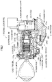
- FIG.2 is a longitudinal cross-sectional view schematically showing an inner structure of the steering lock device 1.
- a case 101 of the steering lock device 1 is integrally formed of a metal such as zinc die-cast.
- a key cylinder 110 that has a cylinder 111 and a rotor rotatably housed in the cylinder 111 is mounted in the case 10 by insertion thereinto.
- a key hole 112a into which a key K is inserted is formed in the rotor 112 of the key cylinder 110 so as to extend toward the inside in the axis direction.
- a plurality of tumblers 113, 113, ⁇ ⁇ ⁇ having an elongate shape in the diameter direction (vertical direction) of the rotor 112 are housed in the rotor 112 along the longitudinal direction thereof in a movable state.
- Each end portion of tumblers 113, 113, ⁇ ⁇ ⁇ projects from an outer periphery of the rotor 112 so as to engages with an inner periphery of the cylinder 111 in a state that the key K is not inserted therein, thereby the rotor 112 is restrained from being rotated.
- each tumbler 113, 113, ⁇ ⁇ ⁇ corresponding to an end surface of a mountain-groove shape of the key K engages with the end surface of the key K so that all of the tumblers 113, 113, ⁇ ⁇ ⁇ evacuate from the outer periphery of the rotor 112. Thereby, it becomes possible to carry out rotation operation of the rotor 112.
- a slide piece 114 is mounted in the front lower side of the rotor 112 in the diameter direction in a movable state.
- the outer surface of the slide piece 114 is curved at the same curvature as that of the outer surface of the rotor 112, so that the rotor 112 and the slide piece 114 are configured to be integrally rotated in the key cylinder 110.
- the slide piece 114 in a state that the key K is inserted into the rotor 112, the slide piece 114 is restrained from moving in the center direction of the rotor 112 by that the end portion thereof is brought into contact with a part of the key K.
- An antilock lever 115 that is an elongated movable member is mounted in the lower part of the key cylinder 110, parallel to the center axis of the key cylinder 110 and rotatably around a shaft of the central part thereof.
- a front end part 115a is formed in the front end of the antilock lever 115 so as to be bent toward the slide piece 114 located at the upper position, and a back end part 115b that is capable of engaging with an engaging projection 203b of a slider 203 described below is formed in the back end thereof.
- elastic force acts on the antilock lever 115 in a direction (elevating direction) from the front end part 115a to the slide piece 114 by a spring or the like (not shown).
- a cam shaft 116 is formed so as to be combined with a rear shaft of the rotor 112.
- the cam shaft 116 includes an outer tubular part 116a having an approximately cylindrical shape and an inner tubular part 116b having an approximately cylindrical shape similarly so that both are integrally formed at the front part in combination with each other.
- the rear shaft 112b of the rotor 112 is fitted to an inner periphery of the inner tubular part 116b of the cam shaft 116, and simultaneously a rear end part of the inner tubular part 116b projects from the case 101 so as to be combined with the ignition switch unit 40.
- the rotor 112 of the key cylinder 110 is operated to be rotated by the proper key K, so that the ignition switch unit 40 is operated via the cam shaft 116.
- a torsion spring 117 is housed in a space between the outer tubular part 116a and the inner tubular part 116b of the cam shaft 116.
- One end of the torsion spring 117 engages with the outer tubular part 116a of the cam shaft 116, thus when the rotor 112 of the key cylinder 110 reaches an "ON" position by rotation operation of the key K, another end of the torsion spring 117 engages with the case 101, thereby a spring force acts on the cam shaft 116 in the direction in which operation of the key K is returned from a "START" position to the "ON" position.
- a cam surface 116c is formed in a lower part of the outer tubular part 116a of the cam shaft 116, that slides in contact with a follower part 203a of a slider 203 described below.
- the steering lock part 20 includes a lock bar 201, a compression spring 202 and the slider 203.
- the lock bar 201 is formed of high stiffness metal so as to have a rod-like shape, and the distal end part thereof is mounted in a lower part of the steering lock device 1 so as to be movable back and forth from the case 101 to a side of the steering column 80.
- a spring force always acts on the lock bar 201 in the direction in which it exits from the case 101 by the compression spring 202 housed in the case 101.
- a groove part 201b is formed in an upper part of the lock bar 201, a lower part of the slider 203 is fitted to the groove part 201b. Together with this, a rear surface of upper part of the slider 203 is brought into contact with an inner wall 101 c of rear part of the case 101, thereby the lock bar 201 is prevented from falling out of the case 101.
- the follower part 203a is integrally formed in an upper part of the slider 203 so as to follow in contact with the cam surface 116c of the above-mentioned cam shaft 116.
- an engaging projection 203b capable of engaging with the rear end part 115b of the above-mentioned antilock lever 115 is formed in an upper part of the front portion of the slider 203.
- FIG.3 is a cross-sectional view schematically showing parts of the lock bar 201 and the steering column 80 in the steering lock device 1 shown in FIG.1 .
- a bracket 102 is formed so as to have a semicircular arc shape and one end is openable supported via a hinge shaft 102a in a hinge block part 101b of the case 101.
- the bracket 102 is opened, the steering column 80 is fixed to the case 101 and another end is fixed to a boss block part 101a via a bolt 103 in a state that the bracket 102 is closed, thereby the steering column 80 is mounted in the steering lock device 1.
- the slide piece 114 in a state that the key K is removed from the key hole 112a, the slide piece 114 is not restrained from moving, thereby slide piece 114 is elevated by the front end part 115a of the antilock lever 115, and simultaneously the back end part 115b of the antilock lever 115 descends.
- the engaging projection 203b of the slider 203 and the back end part 115b of the antilock lever 115 can not engage with each other, thus the lock bar 201 advances toward the lock position by the elastic expansion force of the compression spring 202 and simultaneously the rear surface of upper part of the slider 203 fitting to the groove part 201b of the lock bar 201 is brought into contact with the inner wall of rear part of the case 101, thereby the lock bar 201 is maintained in the lock position.
- the cam shaft 116 is rotated in conjunction with rotation of the rotor 112, thereby the slider 203 and the engaging projection 203b in the front part of the slider 203 move forward together with the follower part 203a that follows in contact with the cam surface 116c of the cam shaft 116, and further the lock bar 201 that fits to the slider 203 in the groove part 201b evacuates to the unlock position.
- the engaging projection 203b engages with the rear end part 115b of the antilock lever 115, thereby the slider 203 is held at the position, and simultaneously the lock bar 201 fitting to the slider 203 is held at the unlock position.
- interlock unit 30 as a key interlock device according to an embodiment of the present invention will be explained.
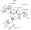
- FIG.4 is an exploded perspective view schematically showing an internal constitution of the interlock unit 30 as the key interlock device according to an embodiment of the present invention.
- the interlock unit 30 includes a case member 31 and a cover member 32, and a holding solenoid 33, a link 34, a release link 35 and a torsion spring 37 that are housed in the case member 31 and the cover member 32.
- the case member 31 is integrally formed of a resin material having good heat conductivity such as PBT containing glass fibers by an injection molding.
- the case member 31 has an outer shape of an approximate rectangle, and is formed so as to have a frame-like shape of which front and rear parts are mostly opened.
- a screw bracket part 31 a having a hole 311 is formed to project, and at a bottom left part opposite to the screw bracket part 31a, an engaging projection part 31b is formed.
- the inner part of the case member 31 in which the engaging projection part 31b is formed is partially opened downward, and simultaneously a bearing part 31c having a cylindrical shape is formed in the side wall part of the case member 31.
- a bearing part 31c having a cylindrical shape is formed in the side wall part of the case member 31.
- fitting projection parts 31 e, 31d having a pin-like shape are formed so as to project, and in a predetermined site of the outer wall part of the case member 31, a plurality of engaging claws 31f are formed.
- the cover member 32 is formed of the same resin material as the case member 31 by an injection molding so as to have an approximately plate-like shape.
- the cover member 32 is a member mounted for blocking the open part in the rear side of the case member 31, in which fitting hole parts 32d, 32e that fit to the fitting projection parts 31e, 31d of the case member 31 are formed, and a plurality of engaging frame parts 32 f that engage with the engaging claws 31f of the case member 31 are formed so as to project.
- a pin pole 32c is formed so as to be opened.
- an open part 32g is formed by that a step part is opened, and simultaneously in the opening end of the open part 32g, a spring engaging part 32h is formed so as to project.
- the holding solenoid 33 includes a plunger 331 and an engaging shaft 332 perpendicular to the plunger 331.
- a harness connector 333 is mounted in the front part of the holding solenoid 33. The holding solenoid 33 becomes in an excited state by that the driving current is supplied, so that the holding solenoid 33 generates holding force (attraction force) restraining the plunger 331 from projecting.
- the holding solenoid 33 is housed in the case member 31 so as to expose the harness connector 333 from the open part of front side of the case member 31 to the outside.
- the link 34 is a reinforcement member integrally formed of a synthetic resin material such as PBT containing glass fibers similarly to the case member 31.
- the link 34 includes an arm part 34c of a linear shape having a pressure receiving surface 34a being flat-shaped in the right side when viewed from the insertion direction of the key K, a rotation shaft part 34b formed in the left basic end side of the arm part 34c, engaging groove parts 34d, 34d having a two-pronged portion bent at an approximately right angle at the position of the rotation shaft part 34b, and a spring engaging part 34e formed in the left front part of one of the engaging groove parts 34d so as to project.
- the release link 35 is a member formed of a resin material having good sliding characteristics such as POM, and has a taper surface 35a having a downward-facing slope formed in the right side when viewed from the insertion direction of the key K.
- a bearing hole 35b into which the rotation shaft part 34b of the link 34 is inserted is formed in the end part opposite to the taper surface 35a so as to be opened.
- the release link 35 is supported by the rotation shaft part 34b of the link 34 at the bearing hole 35b, thereby it is rotatably mounted relatively to the link 34.
- the torsion spring 37 is formed so as to have such a configuration that two spiral parts having the same diameter and axis are combined with each other at a combining part 37c.
- the torsion spring 37 comes into contact with the release link 35 at the combining part 37c, and the two spiral parts are respectively fitted to both end parts of the rotation shaft part 34b of the link 34 so as to stride the link 34 and the release link 35.
- simultaneously one end 37a of the torsion spring 37 engages with the spring engaging part 34e of the link 34.
- the link 34 and the release link 35 are prevented from being removed in the axis direction by being sandwiched between the two spiral parts of the torsion spring 37 and simultaneously elastic force acts in a direction of closing each other.
- the link 34 and the release link 35 are rotatably mounted in the case member 31 by that one end part of the rotation shaft part 34b of the link 34 is fitted to the bearing part 31c of the case member 31, and groove parts of the two-pronged portion of the engaging groove parts 34d, 34d are engaged with the engaging shaft 332 of the holding solenoid 33.
- the arm part 34c of the link 34 and the taper surface 35a of the release link 35 are mounted so as to expose downward from the open part in the lower side of the case member 31.
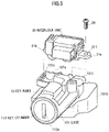
- FIG.5 is a perspective view schematically showing an installation method of the interlock unit 30 as the key interlock device according to one embodiment of the present invention in the steering lock device 1.
- a housing frame part 101 d that houses the interlock unit 30 therein and a screw boss part 101 f are integrally formed with the case 101 at the installing position of the interlock unit 30 in the backward upper part of the key part 10.
- an engaging hole 101 e is formed in the left side wall of the housing frame part 101 d so as to be opened.
- the interlock unit 30 is mounted in the housing frame part 101 d of the steering lock device 1 by that the engaging projection part 31b in the left side is inserted into the engaging hole 101 e of the housing frame part 101 d from the inside so as to be engaged with each other, and then a mounting screw 38 is inserted into the hole 311 of the screw bracket part 31a so as to be fastened to a screw hole of the screw boss part 101 f.
- FIG.6A is a front view schematically showing an inner structure of the interlock unit 30 as the key interlock device according to one embodiment of the present invention when viewed from the insertion direction of the key K, in which the interlock unit 30 is in an interlock state.
- FIG.6B is a front view schematically showing an inner structure of the interlock unit 30 as the key interlock device according to one embodiment of the present invention, in which the interlock unit 30 is in a state that the interlock state is released.
- the link 34 transmits a rotation restraining force generated by the holding solenoid 33 in an excited state to the cam shaft 116.
- the rotation shaft part 34b and the pin 36 of the link 34 are arranged on an extension of a line of force of the rotation operation force of the key K generated in the tangential direction of the cam shaft 116.
- the link 34 is restrained from being rotated by the holding solenoid 33, so that a state that an action surface 116d of the cam shaft 116 and the pressure receiving surface 34a of the arm part 34c of the link 34 are brought into contact with each other is maintained.
- the rotation operation force by the key K is received at the rotation shaft part 34b and the pin 36 passing through the rotation shaft part 34b located on an extension of a line of force thereof, and simultaneously a rotation restraining force as the counteraction is transmitted to the cam shaft 116 via the link 34, so that the rotation operation of the key K in the direction returning to the "LOCK" position is locked.
- the rotation shaft part 34b for rotatably supporting the link 34 and the pin 36 penetrating through the rotation shaft part 34b are disposed on a line of force of the rotation operation force generated in the tangential direction of the cam shaft 116 operated by the key K.
- the rotation operation force from the cam shaft 116 is received at the rotation shaft part 34b and the pin 36, thereby the burden of a load to the link 34 can be reduced.
- the arm part 34c of the link 34 is formed so as to have a shape extending linearly from the rotation shaft part 34b as a center, so that only compression load component acts on the arm part 34c without bending stress component.
- the link mechanism of the above-mentioned configuration is adopted as a reinforcement part of the holding solenoid 33, so that as a material of the link 34 and the like, a resin having high resistance to a compression load such as PBT can be used instead of metal, so that high production costs can be reduced.
- the engaging projection part 31b is formed in one end part of the interlock unit 30, and the engaging projection part 31b is engaged with the housing frame part 101 d of the steering lock device 1 so that the interlock unit 30 is mounted.
- the engaging projection part 31b that allows the interlock unit 30 to engage with the steering lock device 1 is formed in a side (the left side when viewed from the insertion direction of the key K) on which the rotation operation force acts, the rotation operation force being directed toward the direction in which the key K is returned to the "LOCK" position at the interlock state.
Landscapes
- Engineering & Computer Science (AREA)
- Mechanical Engineering (AREA)
- Lock And Its Accessories (AREA)
Claims (8)
- Schlüsselverriegelungsvorrichtung (30), umfassend:einen Haftmagneten (33), der dazu eingerichtet ist, wirksam zu sein, um einen Kolben (331) zu halten, und ein Verbindungselement (34), das um eine eine Drehachse (36) definierende Achse (36) drehbar ist und für den Eingriff mit dem Kolben (331) eingerichtet ist und dazu eingerichtet ist, eine Kraft einer versuchten Betätigung eines Schlüssels aufzunehmen und eine entgegengesetzte Reaktionsrückhaltekraft zu übertragen, um der Kraft der versuchten Betätigung des Schlüssels entgegenzuwirken;wobei die Achse (36) und Drehachse des Verbindungselements (34) auf einer virtuellen Linie angeordnet ist, entlang derer die versuchte Kraft des Schlüssels ausgeübt werden soll;wobei die Verriegelungsvorrichtung (30) ferner ein Gehäuseelement (31) umfasst, das den Haftmagneten (33) und das Verbindungselement (34) unterbringt, und einen Eingriffsteil (31b) aufweist, durch den die Schlüsselverriegelungsvorrichtung zum Anbringen an einem Körper (101) einer Lenkradschlossvorrichtung (1) eingerichtet ist, und wobei der Eingriffsteil (31b) auf der gegenüberliegenden Seite der Achse (36) angeordnet ist, auf die die Kraft der versuchten Betätigung des Schlüssels ausgeübt werden soll;wobei das Verbindungselement (34) einen geradlinigen Armteil (34c) umfasst, der sich entlang der virtuellen Linie erstreckt; undwobei der Eingriffsteil (31b) für den Eingriff mit einer Seitenwand eines Einhausungsrahmenteils (101d) der Lenkradschlossvorrichtung (1) eingerichtet ist,und durch welchen die Lenkradschlossvorrichtung (1) die Kraft der versuchten Betätigung des Schlüssels aufnehmen soll.
- Vorrichtung nach Anspruch 1, wobei der Magnet (33) dazu eingerichtet ist, den Kolben (331) zu halten, wenn er erregt ist.
- Vorrichtung nach Anspruch 1 oder 2, wobei das Verbindungselement (34) für den Eingriff mit dem Kolben (331), wenn der Magnet (33) erregt ist, eingerichtet ist.
- Vorrichtung nach Anspruch 1, wobei das Verbindungselement (34) die Achse umfasst.
- Vorrichtung nach Anspruch 1, wobei der Eingriffsteil (31b) an einem Ende der Schlüsselverriegelungsvorrichtung (30) angeordnet ist und dazu angepasst ist, in eine Öffnung (101e) des Körpers der Lenkradschlossvorrichtung (1) eingesteckt zu werden, und
die Schlüsselverriegelungsvorrichtung dazu eingerichtet ist, an einem anderen Ende davon an dem Körper der Lenkradschlossvorrichtung befestigt zu werden. - Vorrichtung nach Anspruch 1 oder 5, wobei der Eingriffsteil (31b) dazu eingerichtet ist, an einem Ende der Schlüsselverriegelungsvorrichtung (30) in einer Richtung des Zurückdrehens des Schlüssels aus einer ACC-Stellung in eine LOCK-Stellung davon angeordnet zu werden.
- Vorrichtung nach Anspruch 1, wobei der Armteil (34c) eine Druckaufnahmefläche (34a) an einem Ende umfasst, und
die Druckaufnahmefläche (34a) für den Kontakt mit einer Wirkfläche (116d) eingerichtet ist, auf die die Betätigungskraft des Schlüssels ausgeübt wird. - Vorrichtung nach Anspruch 7, wobei die Druckaufnahmefläche (34a) für den Kontakt mit der Wirkfläche (116d) eingerichtet ist, um den Schlüssel daran zu hindern, aus einer ACC-Stellung in eine LOCK-Stellung davon zurückgedreht zu werden, wenn der Magnet (33) erregt ist.
Applications Claiming Priority (1)
| Application Number | Priority Date | Filing Date | Title |
|---|---|---|---|
| JP2010131109A JP5431250B2 (ja) | 2010-06-08 | 2010-06-08 | キーインターロック装置 |
Publications (3)
| Publication Number | Publication Date |
|---|---|
| EP2394871A2 EP2394871A2 (de) | 2011-12-14 |
| EP2394871A3 EP2394871A3 (de) | 2013-07-03 |
| EP2394871B1 true EP2394871B1 (de) | 2022-09-21 |
Family
ID=44118189
Family Applications (1)
| Application Number | Title | Priority Date | Filing Date |
|---|---|---|---|
| EP11168608.5A Active EP2394871B1 (de) | 2010-06-08 | 2011-06-02 | Schlüsselverriegelungsvorrichtung |
Country Status (5)
| Country | Link |
|---|---|
| US (1) | US8756962B2 (de) |
| EP (1) | EP2394871B1 (de) |
| JP (1) | JP5431250B2 (de) |
| KR (1) | KR101521675B1 (de) |
| CN (1) | CN102363420B (de) |
Families Citing this family (12)
| Publication number | Priority date | Publication date | Assignee | Title |
|---|---|---|---|---|
| FR2952332B1 (fr) * | 2009-11-06 | 2013-11-29 | Valeo Securite Habitacle | Dispositif antivol pour colonne de direction de vehicule a super condamnation assuree par bascule intermediaire |
| JP5520683B2 (ja) * | 2010-05-11 | 2014-06-11 | 株式会社東海理化電機製作所 | イグニッションスイッチの操作規制機構 |
| FR2965230B1 (fr) * | 2010-09-28 | 2020-02-28 | U-Shin France Sas | Antivol de direction pour vehicule automobile |
| FR2978403A1 (fr) * | 2011-07-25 | 2013-02-01 | Valeo Securite Habitacle | Dispositif antivol pour colonne de direction et colonne de direction associee |
| JP5935115B2 (ja) * | 2011-11-28 | 2016-06-15 | 株式会社ユーシン | 電動ステアリングロック装置 |
| DE202013009915U1 (de) * | 2012-12-03 | 2014-05-13 | Strattec Security Corporation | Zündschloss-Lenkschloss-Anordnung |
| EP2746113B1 (de) | 2012-12-20 | 2016-11-02 | U-Shin France | Drehblockierungssystem für eine Schlüsselverriegelungsvorrichtung und Schlüsselverriegelungsvorrichtung mit einem derartigen Drehblockierungssystem |
| CN103171138B (zh) * | 2013-03-19 | 2015-03-25 | 江苏新美星包装机械股份有限公司 | 一种底模单边锁定机构 |
| JP6058525B2 (ja) * | 2013-12-11 | 2017-01-11 | 株式会社東海理化電機製作所 | ステアリングロック装置 |
| JP6423255B2 (ja) * | 2014-11-27 | 2018-11-14 | 株式会社ユーシン | ステアリングロック装置 |
| JP6434288B2 (ja) * | 2014-11-27 | 2018-12-05 | 株式会社ユーシン | ステアリングロック装置 |
| JP6746949B2 (ja) * | 2016-02-25 | 2020-08-26 | オムロン株式会社 | ハンドルロック機構、ハンドルロック装置および移動体 |
Citations (2)
| Publication number | Priority date | Publication date | Assignee | Title |
|---|---|---|---|---|
| JPS588443A (ja) * | 1981-07-08 | 1983-01-18 | Nissan Motor Co Ltd | 自動車のステアリングロック装置 |
| JP2001301571A (ja) * | 2000-04-25 | 2001-10-31 | Tokai Rika Co Ltd | 車両用エンジン始動装置 |
Family Cites Families (30)
| Publication number | Priority date | Publication date | Assignee | Title |
|---|---|---|---|---|
| US3596483A (en) * | 1969-07-09 | 1971-08-03 | Gen Motors Corp | Steering column lock |
| US3613412A (en) * | 1970-08-17 | 1971-10-19 | Nagatoshi Suzuki | Steering column lock |
| FR2208432A5 (de) * | 1972-11-24 | 1974-06-21 | Neiman Exploitation Brevets | |
| DE2607609C3 (de) * | 1976-02-25 | 1980-12-04 | Rudolf 6000 Frankfurt Eichenauer | Lenkschloß für Kraftfahrzeuge |
| US4318288A (en) * | 1979-04-30 | 1982-03-09 | Rifat Sultan A | Steering column lock |
| IT1129385B (it) * | 1980-11-28 | 1986-06-04 | Arman Spa | Dispositivo antifurto bloccasterzo per autoveicoli |
| EP0059595B1 (de) * | 1981-02-27 | 1986-08-20 | Nissan Motor Co., Ltd. | Lenkschlossaufbau |
| DE3213719C2 (de) * | 1982-04-14 | 1984-08-23 | Neiman GmbH, 5657 Haan | Vorrichtung zum Sperren der Drehbewegung einer Lenkspindel eines Kraftfahrzeugs |
| DE3616122C2 (de) * | 1986-05-13 | 1997-05-15 | Ymos Ag Ind Produkte | Lenk- und Zündschloß |
| US4945740A (en) * | 1987-12-19 | 1990-08-07 | Honda Lock Mfg. Co., Ltd. | Vehicle steering lock device |
| JP2587086B2 (ja) * | 1988-03-07 | 1997-03-05 | 日産自動車株式会社 | ステアリングロック装置 |
| US5121616A (en) * | 1988-08-04 | 1992-06-16 | Tibbe Kg | Steering lock for motor vehicles |
| US5065604A (en) * | 1990-06-11 | 1991-11-19 | Sparton Corporation | Ignition interlock system |
| JP2530045Y2 (ja) * | 1990-11-09 | 1997-03-26 | 株式会社東海理化電機製作所 | ステアリングロック装置 |
| JP2564909Y2 (ja) * | 1992-10-12 | 1998-03-11 | 株式会社東海理化電機製作所 | ステアリングロック装置 |
| JP3564171B2 (ja) * | 1994-06-08 | 2004-09-08 | 株式会社東海理化電機製作所 | 車両用ロック装置 |
| US5685183A (en) * | 1994-07-19 | 1997-11-11 | Kabushiki Kaisha Tokai Rika Denki Seisakusho | Vehicle locking device |
| WO1996007564A1 (en) * | 1994-09-06 | 1996-03-14 | Mccoolidge James S | Ignition rack and sector gear for a steering column |
| FR2788477B1 (fr) * | 1999-01-15 | 2001-02-16 | Valeo Securite Habitacle | Antivol de direction de vehicule automobile |
| JP4028117B2 (ja) | 1999-02-09 | 2007-12-26 | 株式会社東海理化電機製作所 | キーロック装置 |
| JP3668662B2 (ja) * | 2000-02-16 | 2005-07-06 | 富士機工株式会社 | コラム式自動変速機操作装置のキーインターロック機構 |
| DE10101983A1 (de) * | 2001-01-18 | 2002-07-25 | Bayerische Motoren Werke Ag | Sicherheitseinrichtung für ein Kraftfahrzeug |
| JP3781644B2 (ja) * | 2001-07-19 | 2006-05-31 | 株式会社ユーシン | ステアリングロック装置 |
| JP3798294B2 (ja) * | 2001-10-31 | 2006-07-19 | 株式会社ユーシン | ステアリングロック装置 |
| JP3838630B2 (ja) * | 2002-02-27 | 2006-10-25 | 株式会社ホンダロック | 車両用エンジン始動装置 |
| EP1378406B1 (de) * | 2002-05-29 | 2006-09-06 | Kabushiki Kaisha Tokai Rika Denki Seisakusho | Vorrichtung zur Verhinderung der Aktivierung eines Motoranlassersystems |
| DE10320154B3 (de) * | 2003-05-06 | 2005-02-17 | Huf Hülsbeck & Fürst Gmbh & Co. Kg | Vorrichtung zum Sperren der Lenkspindel eines Kraftfahrzeugs |
| JP4767593B2 (ja) * | 2005-06-02 | 2011-09-07 | 株式会社ホンダロック | 車両用イグニッションスイッチの操作装置 |
| JP5118079B2 (ja) * | 2009-02-03 | 2013-01-16 | 株式会社東海理化電機製作所 | キー装置 |
| JP5118077B2 (ja) * | 2009-02-03 | 2013-01-16 | 株式会社東海理化電機製作所 | キー装置 |
-
2010
- 2010-06-08 JP JP2010131109A patent/JP5431250B2/ja active Active
-
2011
- 2011-06-02 EP EP11168608.5A patent/EP2394871B1/de active Active
- 2011-06-03 US US13/152,517 patent/US8756962B2/en active Active
- 2011-06-08 KR KR1020110055259A patent/KR101521675B1/ko not_active Expired - Fee Related
- 2011-06-08 CN CN201110159128.9A patent/CN102363420B/zh active Active
Patent Citations (2)
| Publication number | Priority date | Publication date | Assignee | Title |
|---|---|---|---|---|
| JPS588443A (ja) * | 1981-07-08 | 1983-01-18 | Nissan Motor Co Ltd | 自動車のステアリングロック装置 |
| JP2001301571A (ja) * | 2000-04-25 | 2001-10-31 | Tokai Rika Co Ltd | 車両用エンジン始動装置 |
Also Published As
| Publication number | Publication date |
|---|---|
| EP2394871A3 (de) | 2013-07-03 |
| EP2394871A2 (de) | 2011-12-14 |
| US20110296881A1 (en) | 2011-12-08 |
| KR20110134331A (ko) | 2011-12-14 |
| JP5431250B2 (ja) | 2014-03-05 |
| CN102363420B (zh) | 2014-12-10 |
| KR101521675B1 (ko) | 2015-05-19 |
| US8756962B2 (en) | 2014-06-24 |
| CN102363420A (zh) | 2012-02-29 |
| JP2011255761A (ja) | 2011-12-22 |
Similar Documents
| Publication | Publication Date | Title |
|---|---|---|
| EP2394871B1 (de) | Schlüsselverriegelungsvorrichtung | |
| US20120110920A1 (en) | Vehicle door lock device | |
| US7478846B2 (en) | Door lock device and assembling method thereof | |
| CN102741096B (zh) | 用于机动车的转向盘锁装置 | |
| TWI739953B (zh) | 車輛用門鎖裝置 | |
| US7559586B2 (en) | Door lock apparatus for a vehicle | |
| EP2213532B1 (de) | Schlüsselregelvorrichtung | |
| US20120080892A1 (en) | Door handle device for vehicle | |
| US6487883B2 (en) | Shift lever apparatus | |
| KR20140005363A (ko) | 잠금 장치 | |
| EP2213530B1 (de) | Schlüsselvorrichtung | |
| JP6687852B2 (ja) | 車両用ドアロック装置 | |
| JP2013185335A (ja) | 車両のドアラッチ装置 | |
| US10017151B2 (en) | Steering lock device | |
| US20190352944A1 (en) | Handle comprising a movable lock cylinder unit | |
| JP6007129B2 (ja) | ドアロック装置 | |
| JP2008190189A (ja) | 錠装置 | |
| KR100655715B1 (ko) | 차량용 잠금장치 | |
| JP5538871B2 (ja) | 錠前 | |
| JP5368963B2 (ja) | 錠前 | |
| KR100573497B1 (ko) | 비상 손잡이 일체형 트렁크 리드래치 | |
| JP3546910B2 (ja) | ドアロック機構 | |
| JP2013063725A (ja) | ステアリングロック装置 | |
| KR20090118567A (ko) | 게이트형 변속레버의 키 인터록장치 |
Legal Events
| Date | Code | Title | Description |
|---|---|---|---|
| AK | Designated contracting states |
Kind code of ref document: A2 Designated state(s): AL AT BE BG CH CY CZ DE DK EE ES FI FR GB GR HR HU IE IS IT LI LT LU LV MC MK MT NL NO PL PT RO RS SE SI SK SM TR |
|
| AX | Request for extension of the european patent |
Extension state: BA ME |
|
| PUAI | Public reference made under article 153(3) epc to a published international application that has entered the european phase |
Free format text: ORIGINAL CODE: 0009012 |
|
| PUAL | Search report despatched |
Free format text: ORIGINAL CODE: 0009013 |
|
| AK | Designated contracting states |
Kind code of ref document: A3 Designated state(s): AL AT BE BG CH CY CZ DE DK EE ES FI FR GB GR HR HU IE IS IT LI LT LU LV MC MK MT NL NO PL PT RO RS SE SI SK SM TR |
|
| AX | Request for extension of the european patent |
Extension state: BA ME |
|
| RIC1 | Information provided on ipc code assigned before grant |
Ipc: B60R 25/02 20130101AFI20130529BHEP |
|
| 17P | Request for examination filed |
Effective date: 20131121 |
|
| RBV | Designated contracting states (corrected) |
Designated state(s): AL AT BE BG CH CY CZ DE DK EE ES FI FR GB GR HR HU IE IS IT LI LT LU LV MC MK MT NL NO PL PT RO RS SE SI SK SM TR |
|
| 17Q | First examination report despatched |
Effective date: 20150710 |
|
| GRAP | Despatch of communication of intention to grant a patent |
Free format text: ORIGINAL CODE: EPIDOSNIGR1 |
|
| STAA | Information on the status of an ep patent application or granted ep patent |
Free format text: STATUS: GRANT OF PATENT IS INTENDED |
|
| INTG | Intention to grant announced |
Effective date: 20220503 |
|
| GRAS | Grant fee paid |
Free format text: ORIGINAL CODE: EPIDOSNIGR3 |
|
| GRAA | (expected) grant |
Free format text: ORIGINAL CODE: 0009210 |
|
| STAA | Information on the status of an ep patent application or granted ep patent |
Free format text: STATUS: THE PATENT HAS BEEN GRANTED |
|
| AK | Designated contracting states |
Kind code of ref document: B1 Designated state(s): AL AT BE BG CH CY CZ DE DK EE ES FI FR GB GR HR HU IE IS IT LI LT LU LV MC MK MT NL NO PL PT RO RS SE SI SK SM TR |
|
| REG | Reference to a national code |
Ref country code: GB Ref legal event code: FG4D |
|
| REG | Reference to a national code |
Ref country code: CH Ref legal event code: EP |
|
| REG | Reference to a national code |
Ref country code: DE Ref legal event code: R096 Ref document number: 602011073300 Country of ref document: DE |
|
| REG | Reference to a national code |
Ref country code: IE Ref legal event code: FG4D |
|
| REG | Reference to a national code |
Ref country code: AT Ref legal event code: REF Ref document number: 1519806 Country of ref document: AT Kind code of ref document: T Effective date: 20221015 |
|
| REG | Reference to a national code |
Ref country code: LT Ref legal event code: MG9D |
|
| REG | Reference to a national code |
Ref country code: NL Ref legal event code: MP Effective date: 20220921 |
|
| PG25 | Lapsed in a contracting state [announced via postgrant information from national office to epo] |
Ref country code: SE Free format text: LAPSE BECAUSE OF FAILURE TO SUBMIT A TRANSLATION OF THE DESCRIPTION OR TO PAY THE FEE WITHIN THE PRESCRIBED TIME-LIMIT Effective date: 20220921 Ref country code: RS Free format text: LAPSE BECAUSE OF FAILURE TO SUBMIT A TRANSLATION OF THE DESCRIPTION OR TO PAY THE FEE WITHIN THE PRESCRIBED TIME-LIMIT Effective date: 20220921 Ref country code: NO Free format text: LAPSE BECAUSE OF FAILURE TO SUBMIT A TRANSLATION OF THE DESCRIPTION OR TO PAY THE FEE WITHIN THE PRESCRIBED TIME-LIMIT Effective date: 20221221 Ref country code: LV Free format text: LAPSE BECAUSE OF FAILURE TO SUBMIT A TRANSLATION OF THE DESCRIPTION OR TO PAY THE FEE WITHIN THE PRESCRIBED TIME-LIMIT Effective date: 20220921 Ref country code: LT Free format text: LAPSE BECAUSE OF FAILURE TO SUBMIT A TRANSLATION OF THE DESCRIPTION OR TO PAY THE FEE WITHIN THE PRESCRIBED TIME-LIMIT Effective date: 20220921 Ref country code: FI Free format text: LAPSE BECAUSE OF FAILURE TO SUBMIT A TRANSLATION OF THE DESCRIPTION OR TO PAY THE FEE WITHIN THE PRESCRIBED TIME-LIMIT Effective date: 20220921 |
|
| REG | Reference to a national code |
Ref country code: AT Ref legal event code: MK05 Ref document number: 1519806 Country of ref document: AT Kind code of ref document: T Effective date: 20220921 |
|
| PG25 | Lapsed in a contracting state [announced via postgrant information from national office to epo] |
Ref country code: HR Free format text: LAPSE BECAUSE OF FAILURE TO SUBMIT A TRANSLATION OF THE DESCRIPTION OR TO PAY THE FEE WITHIN THE PRESCRIBED TIME-LIMIT Effective date: 20220921 Ref country code: GR Free format text: LAPSE BECAUSE OF FAILURE TO SUBMIT A TRANSLATION OF THE DESCRIPTION OR TO PAY THE FEE WITHIN THE PRESCRIBED TIME-LIMIT Effective date: 20221222 |
|
| PG25 | Lapsed in a contracting state [announced via postgrant information from national office to epo] |
Ref country code: SM Free format text: LAPSE BECAUSE OF FAILURE TO SUBMIT A TRANSLATION OF THE DESCRIPTION OR TO PAY THE FEE WITHIN THE PRESCRIBED TIME-LIMIT Effective date: 20220921 Ref country code: RO Free format text: LAPSE BECAUSE OF FAILURE TO SUBMIT A TRANSLATION OF THE DESCRIPTION OR TO PAY THE FEE WITHIN THE PRESCRIBED TIME-LIMIT Effective date: 20220921 Ref country code: PT Free format text: LAPSE BECAUSE OF FAILURE TO SUBMIT A TRANSLATION OF THE DESCRIPTION OR TO PAY THE FEE WITHIN THE PRESCRIBED TIME-LIMIT Effective date: 20230123 Ref country code: ES Free format text: LAPSE BECAUSE OF FAILURE TO SUBMIT A TRANSLATION OF THE DESCRIPTION OR TO PAY THE FEE WITHIN THE PRESCRIBED TIME-LIMIT Effective date: 20220921 Ref country code: CZ Free format text: LAPSE BECAUSE OF FAILURE TO SUBMIT A TRANSLATION OF THE DESCRIPTION OR TO PAY THE FEE WITHIN THE PRESCRIBED TIME-LIMIT Effective date: 20220921 Ref country code: AT Free format text: LAPSE BECAUSE OF FAILURE TO SUBMIT A TRANSLATION OF THE DESCRIPTION OR TO PAY THE FEE WITHIN THE PRESCRIBED TIME-LIMIT Effective date: 20220921 |
|
| PG25 | Lapsed in a contracting state [announced via postgrant information from national office to epo] |
Ref country code: SK Free format text: LAPSE BECAUSE OF FAILURE TO SUBMIT A TRANSLATION OF THE DESCRIPTION OR TO PAY THE FEE WITHIN THE PRESCRIBED TIME-LIMIT Effective date: 20220921 Ref country code: PL Free format text: LAPSE BECAUSE OF FAILURE TO SUBMIT A TRANSLATION OF THE DESCRIPTION OR TO PAY THE FEE WITHIN THE PRESCRIBED TIME-LIMIT Effective date: 20220921 Ref country code: IS Free format text: LAPSE BECAUSE OF FAILURE TO SUBMIT A TRANSLATION OF THE DESCRIPTION OR TO PAY THE FEE WITHIN THE PRESCRIBED TIME-LIMIT Effective date: 20230121 Ref country code: EE Free format text: LAPSE BECAUSE OF FAILURE TO SUBMIT A TRANSLATION OF THE DESCRIPTION OR TO PAY THE FEE WITHIN THE PRESCRIBED TIME-LIMIT Effective date: 20220921 |
|
| REG | Reference to a national code |
Ref country code: DE Ref legal event code: R097 Ref document number: 602011073300 Country of ref document: DE |
|
| PG25 | Lapsed in a contracting state [announced via postgrant information from national office to epo] |
Ref country code: NL Free format text: LAPSE BECAUSE OF FAILURE TO SUBMIT A TRANSLATION OF THE DESCRIPTION OR TO PAY THE FEE WITHIN THE PRESCRIBED TIME-LIMIT Effective date: 20220921 Ref country code: AL Free format text: LAPSE BECAUSE OF FAILURE TO SUBMIT A TRANSLATION OF THE DESCRIPTION OR TO PAY THE FEE WITHIN THE PRESCRIBED TIME-LIMIT Effective date: 20220921 |
|
| PLBE | No opposition filed within time limit |
Free format text: ORIGINAL CODE: 0009261 |
|
| STAA | Information on the status of an ep patent application or granted ep patent |
Free format text: STATUS: NO OPPOSITION FILED WITHIN TIME LIMIT |
|
| PG25 | Lapsed in a contracting state [announced via postgrant information from national office to epo] |
Ref country code: DK Free format text: LAPSE BECAUSE OF FAILURE TO SUBMIT A TRANSLATION OF THE DESCRIPTION OR TO PAY THE FEE WITHIN THE PRESCRIBED TIME-LIMIT Effective date: 20220921 |
|
| PGFP | Annual fee paid to national office [announced via postgrant information from national office to epo] |
Ref country code: DE Payment date: 20230404 Year of fee payment: 13 |
|
| 26N | No opposition filed |
Effective date: 20230622 |
|
| PG25 | Lapsed in a contracting state [announced via postgrant information from national office to epo] |
Ref country code: SI Free format text: LAPSE BECAUSE OF FAILURE TO SUBMIT A TRANSLATION OF THE DESCRIPTION OR TO PAY THE FEE WITHIN THE PRESCRIBED TIME-LIMIT Effective date: 20220921 |
|
| PG25 | Lapsed in a contracting state [announced via postgrant information from national office to epo] |
Ref country code: MC Free format text: LAPSE BECAUSE OF FAILURE TO SUBMIT A TRANSLATION OF THE DESCRIPTION OR TO PAY THE FEE WITHIN THE PRESCRIBED TIME-LIMIT Effective date: 20220921 |
|
| PG25 | Lapsed in a contracting state [announced via postgrant information from national office to epo] |
Ref country code: MC Free format text: LAPSE BECAUSE OF FAILURE TO SUBMIT A TRANSLATION OF THE DESCRIPTION OR TO PAY THE FEE WITHIN THE PRESCRIBED TIME-LIMIT Effective date: 20220921 |
|
| REG | Reference to a national code |
Ref country code: CH Ref legal event code: PL |
|
| REG | Reference to a national code |
Ref country code: BE Ref legal event code: MM Effective date: 20230630 |
|
| GBPC | Gb: european patent ceased through non-payment of renewal fee |
Effective date: 20230602 |
|
| PG25 | Lapsed in a contracting state [announced via postgrant information from national office to epo] |
Ref country code: LU Free format text: LAPSE BECAUSE OF NON-PAYMENT OF DUE FEES Effective date: 20230602 |
|
| REG | Reference to a national code |
Ref country code: IE Ref legal event code: MM4A |
|
| PG25 | Lapsed in a contracting state [announced via postgrant information from national office to epo] |
Ref country code: LU Free format text: LAPSE BECAUSE OF NON-PAYMENT OF DUE FEES Effective date: 20230602 |
|
| PG25 | Lapsed in a contracting state [announced via postgrant information from national office to epo] |
Ref country code: IE Free format text: LAPSE BECAUSE OF NON-PAYMENT OF DUE FEES Effective date: 20230602 |
|
| PG25 | Lapsed in a contracting state [announced via postgrant information from national office to epo] |
Ref country code: IE Free format text: LAPSE BECAUSE OF NON-PAYMENT OF DUE FEES Effective date: 20230602 Ref country code: CH Free format text: LAPSE BECAUSE OF NON-PAYMENT OF DUE FEES Effective date: 20230630 Ref country code: GB Free format text: LAPSE BECAUSE OF NON-PAYMENT OF DUE FEES Effective date: 20230602 |
|
| PG25 | Lapsed in a contracting state [announced via postgrant information from national office to epo] |
Ref country code: IT Free format text: LAPSE BECAUSE OF FAILURE TO SUBMIT A TRANSLATION OF THE DESCRIPTION OR TO PAY THE FEE WITHIN THE PRESCRIBED TIME-LIMIT Effective date: 20220921 Ref country code: FR Free format text: LAPSE BECAUSE OF NON-PAYMENT OF DUE FEES Effective date: 20230630 Ref country code: BE Free format text: LAPSE BECAUSE OF NON-PAYMENT OF DUE FEES Effective date: 20230630 |
|
| PG25 | Lapsed in a contracting state [announced via postgrant information from national office to epo] |
Ref country code: BG Free format text: LAPSE BECAUSE OF FAILURE TO SUBMIT A TRANSLATION OF THE DESCRIPTION OR TO PAY THE FEE WITHIN THE PRESCRIBED TIME-LIMIT Effective date: 20220921 |
|
| PG25 | Lapsed in a contracting state [announced via postgrant information from national office to epo] |
Ref country code: BG Free format text: LAPSE BECAUSE OF FAILURE TO SUBMIT A TRANSLATION OF THE DESCRIPTION OR TO PAY THE FEE WITHIN THE PRESCRIBED TIME-LIMIT Effective date: 20220921 |
|
| REG | Reference to a national code |
Ref country code: DE Ref legal event code: R119 Ref document number: 602011073300 Country of ref document: DE |
|
| PG25 | Lapsed in a contracting state [announced via postgrant information from national office to epo] |
Ref country code: DE Free format text: LAPSE BECAUSE OF NON-PAYMENT OF DUE FEES Effective date: 20250101 |
|
| PG25 | Lapsed in a contracting state [announced via postgrant information from national office to epo] |
Ref country code: CY Free format text: LAPSE BECAUSE OF FAILURE TO SUBMIT A TRANSLATION OF THE DESCRIPTION OR TO PAY THE FEE WITHIN THE PRESCRIBED TIME-LIMIT; INVALID AB INITIO Effective date: 20110602 |
|
| PG25 | Lapsed in a contracting state [announced via postgrant information from national office to epo] |
Ref country code: HU Free format text: LAPSE BECAUSE OF FAILURE TO SUBMIT A TRANSLATION OF THE DESCRIPTION OR TO PAY THE FEE WITHIN THE PRESCRIBED TIME-LIMIT; INVALID AB INITIO Effective date: 20110602 |
|
| PG25 | Lapsed in a contracting state [announced via postgrant information from national office to epo] |
Ref country code: TR Free format text: LAPSE BECAUSE OF FAILURE TO SUBMIT A TRANSLATION OF THE DESCRIPTION OR TO PAY THE FEE WITHIN THE PRESCRIBED TIME-LIMIT Effective date: 20220921 |