EP2213530B1 - Schlüsselvorrichtung - Google Patents
Schlüsselvorrichtung Download PDFInfo
- Publication number
- EP2213530B1 EP2213530B1 EP20100000857 EP10000857A EP2213530B1 EP 2213530 B1 EP2213530 B1 EP 2213530B1 EP 20100000857 EP20100000857 EP 20100000857 EP 10000857 A EP10000857 A EP 10000857A EP 2213530 B1 EP2213530 B1 EP 2213530B1
- Authority
- EP
- European Patent Office
- Prior art keywords
- link
- allowing
- pair
- key
- holding portions
- Prior art date
- Legal status (The legal status is an assumption and is not a legal conclusion. Google has not performed a legal analysis and makes no representation as to the accuracy of the status listed.)
- Not-in-force
Links
- 230000001105 regulatory effect Effects 0.000 claims description 73
- 230000000149 penetrating effect Effects 0.000 claims description 2
- 230000037431 insertion Effects 0.000 description 15
- 238000003780 insertion Methods 0.000 description 15
- 230000006835 compression Effects 0.000 description 8
- 238000007906 compression Methods 0.000 description 8
- 230000002093 peripheral effect Effects 0.000 description 8
- 230000000903 blocking effect Effects 0.000 description 3
- 230000000694 effects Effects 0.000 description 1
- 230000035515 penetration Effects 0.000 description 1
Images


Classifications
-
- B—PERFORMING OPERATIONS; TRANSPORTING
- B60—VEHICLES IN GENERAL
- B60R—VEHICLES, VEHICLE FITTINGS, OR VEHICLE PARTS, NOT OTHERWISE PROVIDED FOR
- B60R25/00—Fittings or systems for preventing or indicating unauthorised use or theft of vehicles
- B60R25/01—Fittings or systems for preventing or indicating unauthorised use or theft of vehicles operating on vehicle systems or fittings, e.g. on doors, seats or windscreens
- B60R25/02—Fittings or systems for preventing or indicating unauthorised use or theft of vehicles operating on vehicle systems or fittings, e.g. on doors, seats or windscreens operating on the steering mechanism
- B60R25/021—Fittings or systems for preventing or indicating unauthorised use or theft of vehicles operating on vehicle systems or fittings, e.g. on doors, seats or windscreens operating on the steering mechanism restraining movement of the steering column or steering wheel hub, e.g. restraining means controlled by ignition switch
- B60R25/02142—Fittings or systems for preventing or indicating unauthorised use or theft of vehicles operating on vehicle systems or fittings, e.g. on doors, seats or windscreens operating on the steering mechanism restraining movement of the steering column or steering wheel hub, e.g. restraining means controlled by ignition switch comprising externally controlled safety devices for preventing locking during vehicle running condition
- B60R25/02144—Fittings or systems for preventing or indicating unauthorised use or theft of vehicles operating on vehicle systems or fittings, e.g. on doors, seats or windscreens operating on the steering mechanism restraining movement of the steering column or steering wheel hub, e.g. restraining means controlled by ignition switch comprising externally controlled safety devices for preventing locking during vehicle running condition interlocked with gear box or gear lever
-
- Y—GENERAL TAGGING OF NEW TECHNOLOGICAL DEVELOPMENTS; GENERAL TAGGING OF CROSS-SECTIONAL TECHNOLOGIES SPANNING OVER SEVERAL SECTIONS OF THE IPC; TECHNICAL SUBJECTS COVERED BY FORMER USPC CROSS-REFERENCE ART COLLECTIONS [XRACs] AND DIGESTS
- Y10—TECHNICAL SUBJECTS COVERED BY FORMER USPC
- Y10T—TECHNICAL SUBJECTS COVERED BY FORMER US CLASSIFICATION
- Y10T70/00—Locks
- Y10T70/50—Special application
- Y10T70/5611—For control and machine elements
- Y10T70/5646—Rotary shaft
- Y10T70/565—Locked stationary
- Y10T70/5655—Housing-carried lock
- Y10T70/5659—Dead bolt
-
- Y—GENERAL TAGGING OF NEW TECHNOLOGICAL DEVELOPMENTS; GENERAL TAGGING OF CROSS-SECTIONAL TECHNOLOGIES SPANNING OVER SEVERAL SECTIONS OF THE IPC; TECHNICAL SUBJECTS COVERED BY FORMER USPC CROSS-REFERENCE ART COLLECTIONS [XRACs] AND DIGESTS
- Y10—TECHNICAL SUBJECTS COVERED BY FORMER USPC
- Y10T—TECHNICAL SUBJECTS COVERED BY FORMER US CLASSIFICATION
- Y10T70/00—Locks
- Y10T70/50—Special application
- Y10T70/5611—For control and machine elements
- Y10T70/5646—Rotary shaft
- Y10T70/565—Locked stationary
- Y10T70/5655—Housing-carried lock
- Y10T70/5664—Latching bolt
-
- Y—GENERAL TAGGING OF NEW TECHNOLOGICAL DEVELOPMENTS; GENERAL TAGGING OF CROSS-SECTIONAL TECHNOLOGIES SPANNING OVER SEVERAL SECTIONS OF THE IPC; TECHNICAL SUBJECTS COVERED BY FORMER USPC CROSS-REFERENCE ART COLLECTIONS [XRACs] AND DIGESTS
- Y10—TECHNICAL SUBJECTS COVERED BY FORMER USPC
- Y10T—TECHNICAL SUBJECTS COVERED BY FORMER US CLASSIFICATION
- Y10T70/00—Locks
- Y10T70/50—Special application
- Y10T70/5889—For automotive vehicles
- Y10T70/5956—Steering mechanism with switch
Definitions
- the present invention relates to a key device that regulates rotation of a key.
- the lifter and the lock plate are supported by a support shaft in a rotatable manner, and a torsion spring is provided at the support shaft.
- US 2003/2333991 A1 discloses a key device comprising: a rotating member that is rotating by rotation of a key; an allowing member that is rotated by the rotating member when the rotating member is rotated to a predetermined rotational position (LOCK); a regulating member that together with the allowing member forms an integral part of a blocking lever and that regulates rotation of the rotating member to the predetermined rotational position by not being rotated together with the allowing member when the rotating member is rotated to the predetermined rotational position and that allows rotation of the rotating member to the predetermined rotational position by being rotated together with the allowing member when the rotating member is rotated to the predetermined rotational position; a pair of holding portions in the form of lugs that hold a supporting shaft supporting the blocking lever; and an urging member in the form of a spring having urging force, wherein axial sliding of the blocking lever on the shaft is restricted due to the end of the spring being held in a U shape notch or by friction.
- LOCK predetermined rotational position
- US 5,685,183 A discloses a generic key device having a rotating member, an allowing member, a regulating member, and an urging member in the sense of claim 1.
- an object of the present invention is to provide a key device that makes it possible to easily assemble an allowing member, a regulating member and an urging member on a subject to be assembled.
- a key device includes: a rotating member that is rotated by rotation of a key; an allowing member that is rotated by the rotating member when the rotating member is rotated to a predetermined rotational position; a regulating member disposed at one side in an extending direction of an axis which supports the allowing member and the regulating member in a rotatable manner of the allowing member, that regulates rotation of the rotating member to the predetermined rotational position by not being rotated together with the allowing member when the rotating member is rotated to the predetermined rotational position, and that allows rotation of the rotating member to the predetermined rotational position by being rotated together with the allowing member when the rotating member is rotated to the predetermined rotational position; a pair of holding portions that protrude toward another side, which is opposite to the one side in the extending direction of the axis, of the allowing member and toward one side of the regulating member, respectively, the axis penetrating through the pair of holding portions, and one of the pair of holding
- the allowing member and the regulating member are rotatable against the urging force of the urging member.
- a key device further includes, in the key device of the first aspect or second aspect, guiding portions provided at the holding portions, that guide the urging member to the pair of holding portions so that the urging member is held by the holding portions.
- a key device further includes, in the key-device of any one of the first, the second or the third aspects, a fitting portion that allows the allowing member and the regulating member to fit with each other such that the allowing member and the regulating member are relatively rotatable.
- a key device further includes, in the key device described in any one of the first, the second, the third and the fourth aspects, protruding portions provided in a subject to which the allowing member, the regulating member and the urging member are assembled, that respectively protrude toward the holding portions to hold the urging member.
- the pair of holding portions are formed at the allowing member and the regulating member, respectively.
- the fitting portion includes a fitting concave portion that is formed at one of the allowing member or the regulating member and a fitting convex portion that is formed at the other of the allowing member or the regulating member, and the fitting concave portion and the fitting convex portion are fitted to each other.
- the pair of holding portions are formed at one of the allowing member or the regulating member.
- the pair of holding portions are formed at one of the allowing member or the regulating member
- the fitting portion is a fitting hole that is formed at the other of the allowing member or the regulating member, and the fitting hole and one of the pair of holding portions are fitted to each other.
- the urging member includes a pair of holding members, and the pair of holding members are respectively held at the pair of holding portions.
- the rotating member is rotated by rotation of a key, and when the rotating member is rotated to the predetermined rotational position, the allowing member is rotated by the rotating member. Further, the regulating member is disposed at one side of the allowing member.
- the regulating member when the rotating member is rotated to the predetermined rotational position, the regulating member is not rotated together with the allowing member, whereby the regulating member regulates rotation of the rotating member to the predetermined rotational position, so as to regulate rotation of the key.
- the regulating member when the rotating member is rotated to the predetermined rotational position, the regulating member is rotated together with the allowing member, whereby the regulating member allows the rotating member to rotate to the predetermined rotational position, so as to allow rotation of the key.
- the pair of holding portions protrude toward another side of the allowing member and toward one side of the regulating member.
- the urging member has urging force, and is held by the pair of holding portions, so as to allow assembling of the allowing member and the regulating member. For this reason, the allowing member, the regulating member and the urging member can be brought into a temporarily assembled state and they can also be easily assembled to a subject to which these members are assembled.
- the allowing member and the regulating member are made rotatable against the urging force of the urging member. For this reason, the allowing member and the regulating member are allowed to return initial position by means of the urging force of the urging member.
- the guiding portions provided in the pair of holding portions guide to hold the urging member in the pair of holding portions. For this reason, the urging member can be easily held by the pair of holding portions.
- the allowing member and the regulating member are fitted with each other by the fitting portion in relatively rotatable manner. For this reason, cancellation of the state in which the allowing member, the regulating member and the urging member are temporarily assembled can be effectively suppressed.
- the protruding portions provided in the subject to which the allowing member, the regulating member and the urging member are assembled protrude toward the holding portions, and hold the urging member. For this reason, when the allowing member, the regulating member and the urging member are assembled to the subject to which these members are assembled, it is possible to suppress cancellation of the state in which the urging member is held.
- Fig. 6 shows a cross sectional view of a steering lock device 10 that serves as a key device according to a first exemplary embodiment of the present invention when seen from the left side.
- the front side of the steering lock device 10 is indicated by arrow FR
- the upper side of the steering lock device 10 is indicated by arrow UP
- the right side of the steering lock device 10 is indicated by arrow RH.
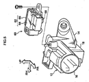
- the steering lock device 10 is equipped with a lock body 12 that serves as an accommodating member, and a fixed piece 14 (see Fig. 5 ) having a substantially semi-cylinder shape is formed at the rear end of the lower side portion of the lock body 12.
- the bracket (not shown in the drawings) having a substantially semi-cylinder shape is mounted to the fixed piece 14.
- a steering post (not shown in the drawings) of a vehicle is fitted in an inner portion of the bracket and the fixed piece 14, whereby the lock body 12 is fixed to the steering post, and the steering lock device 10 is mounted to the steering post.
- a substantially cylinder shaped accommodating cylinder 16 is formed at the upper side portion of the lock body 12, and a rear wall 16A is formed at the rear end of the accommodating cylinder 16.
- a lock cylinder 18 having a substantially rectangular tube shape is formed at the lower side of the rear side portion of the accommodating cylinder 16, and the respective inner sides of the accommodating cylinder 16 and the lock cylinder 18 communicate with each other. The front surface of the lock cylinder 18 is closed, and the rear surface of the lock cylinder 18 is opened toward the rear side via the fixed piece 14.
- a substantially circular cylinder (column) shaped ignition cylinder 20 that serves as a key cylinder is accommodated within the accommodating cylinder 16.
- the front end of the ignition cylinder 20 is made to protrude from the front end of the accommodating cylinder 16 to the front side.
- the front end of the ignition cylinder 20 is disposed in an instrument panel (not shown in the drawings) of a vehicle, and the front surface of the ignition cylinder 20 is directed from the instrument panel to the interior of the vehicle.
- a key rotor 22 having a substantially circular cylinder (column) shape and serving as an insert member is accommodated in the ignition cylinder 20, and front side movement of the key rotor 22 is stopped (not allowed).
- An insertion hole 24 having a rectangular pillar shape is formed within the key rotor 22, and the insertion hole 24 is opened from the front surface of the key rotor 22.
- the key rotor 22 is arranged at a "LOCK" position that serves as a predetermined rotational position, and an ignition key 26 (a regular key) serving as a key can be inserted in and pulled out from the insertion hole 24.
- an ignition key 26 (a regular key) serving as a key
- the key rotor 22 can be rotated in the ignition cylinder 20, whereby the key rotor 22 can be arranged at the "ACC" position, "ON" position or "START" position.
- the ignition key 26 can be inserted in and pulled out from the insertion hole 24, and when the key rotor 22 is arranged at the "ACC" position, "ON” position or “START” position, the operation of the ignition key 26 being inserted in and pulled out from the insertion hole 24 is regulated.
- a slide piece 28 having a substantially U-shaped frame-like configuration is provided in the lower portion of the front portion of the key rotor 22 so as to be movable in the vertical (upper and lower) direction (in the radial direction of the key rotor 22).
- the lower side surface (the outer side surface in the radial direction of the key rotor 22) of the slide piece 28 abuts against the inner peripheral surface of the ignition cylinder 20 so that movement of the slide piece to the lower side direction (to the outer side in the radial direction of the key rotor 22) is stopped (not allowed).
- the lower side surface of the slide piece 28 is curved along the inner peripheral surface of the ignition cylinder 20, and the slide piece 28 is rotatable integrally with the key rotor 22. Further, the lower side surface of the slide piece 28 is opened toward the lower side via the outer peripheral portion of the ignition cylinder 20.
- the upper portion (the inner side portion in the radial direction of the key rotor 22) of the slide piece 28 forms the outer peripheral surface of the insertion hole 24 of the key rotor 22.
- the ignition key 26 regulates movement of the slide piece 28 to the upper side (to the inner side in the radial direction of the key rotor 22).
- movement of the slide piece 28 to the upper side is allowed.
- An elongated plate-shaped lock plate 30 is supported by the lower portion of the ignition cylinder 20 at the intermediate portion in the longitudinal (front and rear) direction in such a manner as to be rotatable and movable in the vertical (upper and lower) direction.
- the lock plate 30 is urged in a direction to which it moves upper side, and further, is urged such that the front end of the lock plate rotates to the upper side and the rear end thereof rotates to the lower side.
- a front side portion and a rear side portion of the lock plate 30 are each formed substantially into an L-shaped plate, and a front end and a rear end of the lock plate 30 are each made to protrude to the upper side.
- the front end of the lock plate 30 passes through (penetrates) the outer peripheral portion of the ignition cylinder 20 and is made to abut against the lower side surface of the slide piece 28.
- movement of the slide piece 28 to the upper side is regulated, whereby rotation of the lock plate 30 by means of the urging force is regulated.
- movement of the slide piece 28 to the upper side is allowed, whereby the front end of the lock plate 30 moves the slide piece 28 to the upper side by means of the urging force, the front end of the lock plate 30 is rotated to the upper side, and the rear end of the lock plate 30 is rotated to the lower side.
- a cam shaft 32 that serves as a rotating member is rotatably accommodated within the accommodating cylinder 16 at the rear side of the ignition cylinder 20.
- a substantially cylinder shaped outer cylinder 34 is provided at the side of the outer periphery of the cam shaft 32 and a substantially cylinder shaped inner cylinder 36 is provided at the side of the inner periphery of the cam shaft 32.
- the outer cylinder 34 and the inner cylinder 36 are integrated with each other at their respective front ends. Further, the inner cylinder 36 passes through (penetrates) the rear wall 16A of the accommodating cylinder 16 and protrudes to the rear side of the accommodating cylinder 16.
- the rear end of the key rotor 22 is fitted into the inner cylinder 36, and the cam shaft 32 is rotatable so as to be integrated with the key rotor 22.
- a return spring 38 that serves as a rotation urging member is accommodated within the outer cylinder 34 on the outer periphery of the inner cylinder 36, and one end (the front side end) of the return spring 38 is connected (latched) to the outer cylinder 34.
- An inclined surface (not shown in the drawings) is formed in the lower side portion of the outer cylinder 34, and the inclined surface is made to slope to a direction which is from the "START” position of the key rotor 22 to the “LOCK” position via the “ON” position and the “ACC” position in accordance from the rear side to the front side.
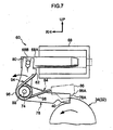
- a regulating surface 40 (see Figs. 7 and 8 ) is formed on the upper side portion of the outer cylinder 34, and the regulating surface 40 is disposed perpendicular to the circumferential direction of the outer cylinder 34.
- An ignition switch 42 is fixed at the rear side of the accommodating cylinder 16, and the inner cylinder 36 rear end of the cam shaft 32 is inserted in the ignition switch 42. As a result, due to the cam shaft 32 being connected to the ignition switch 42 and the cam shaft 32 being rotated integrally with the key rotor 22, the ignition switch 42 can be operated.
- a substantially rectangular pillar shaped slider 44 that serves as a connecting member is accommodated in the accommodating cylinder 16 at the lower side of the cam shaft 32, and the slider 44 is movable (slidable) in the longitudinal (front and rear) direction integrally with a lock bar 54, as described below.
- a moving protrusion 46 having a pillar shape is formed in a rear portion of the slider 44, and the moving protrusion 46 protrudes to the upper side from the slider 44.
- An inclined surface of the cam shaft 32 (outer cylinder 34) comes into contact with the moving protrusion 46 by means of the urging force of a compression spring 58 described later, by this, the slider 44 abuts against the rear wall 16A of the accommodating cylinder 16 such that movement to the rear side is stopped (not allowed), and rotation of the cam shaft 32 is inhibited and the key rotor 22 is, as described above, arranged at the "LOCK" position.
- a plate-shaped engagement hole 48 is formed in the front side portion of the slider 44 at the central part in the horizontal (left and right) direction.
- the engagement hole 48 is opened at the front side, upper side and lower side of the slider 44.
- a substantially trapezoidal plate-shaped engagement protrusion 50 is formed at the front end and upper end of the slider 44 and the engagement protrusion 50 is disposed within the engagement hole 48.
- a rectangular pillar shaped fitting protrusion 52 is formed at the rear end of the slider 44 and the fitting protrusion 52 is made to protrude to the lower side from the slider 44.
- a substantially rectangular pillar shaped lock bar 54 that serves as a lock member is accommodated within the lock cylinder 18.
- the lock bar 54 is guided by the lock cylinder 18 and is movable (slidable) in the longitudinal (front and rear) direction.
- a fitting concave portion 56 having a rectangular pillar shape is formed at the upper end of the front portion of the lock bar 54.
- the fitting concave portion 56 is opened at the upper side from the lock bar 54.
- the fitting protrusion 52 of the slider 44 is fitted into the fitting concave portion 56, and the lock bar 54 can be moved in the longitudinal (front and rear) direction in such a manner as to be integrated with the slider 44.
- a compression spring 58 that serves as lock urging member is bridged between the front end of the lock cylinder 18 and the front end of the lock bar 54.
- the compression spring 58 urges the lock bar 54 and the slider 44 to the rear side.
- the slider 44 is made to abut against the rear wall 16A of the accommodating cylinder 16, and movement of the slider 44 and the lock bar 54 to the rear side is stopped (not allowed).
- the lock bar 54 protrudes to the rear side from the lock cylinder 18 and also protrudes to the rear side from the fixed piece 14.
- the lock bar 54 is made to pass through (penetrates) the above-described steering post and is engaged with the steering shaft (not shown in the drawings) within the steering post. As a result, rotation of the steering shaft is locked and rotation of a steering wheel (not shown in the drawings) which is fixed at the upper end of the steering shaft is locked.
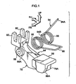
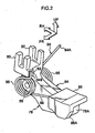
- an interlock unit 60 is mounted at the upper end of the accommodating cylinder 16 at the rear portion of the accommodating cylinder.
- a substantially rectangular parallelepiped box-shaped unit box 62 that is a subject to be assembled is provided at the outer periphery of the interlock unit 60.
- the unit box 62 is formed by a combination of a front side case 64 and a rear side cover 66.
- a lower wall of the unit box 62 is partially opened and the interior of the unit box 62 communicates with the interior of the accommodating cylinder 16.
- a solenoid 68 that serves as a driving section is accommodated within the unit box 62.
- the solenoid 68 includes a circular cylinder (column) shaped plunger 68A serving as a driving member, and the tip end of the plunger 68A is protrude from the solenoid 68 to the right side.
- An engagement shaft 68B in the form of a circular shaft passes through (penetrates) the end of the plunger 68A, and the engagement shaft 68B protrudes from the plunger 68A in the longitudinal (front and rear) direction.
- the solenoid 68 is connected to a shift lever device 72 of the vehicle via a vehicle control device 70.
- a shift lever (not shown in the drawings) of the shift lever device 72 is operated to move to a shift position (an allowable shift position such as an "R" shift position, an "N” shift position, a “D” shift position or the like) other than the "P" shift position (a regulated shift position)
- the solenoid 68 is driven by control of the control device 70, to regulate movement of the plunger 68A to the right side, whereby an increase in the amount of the plunger 68A protruding from the solenoid 68 is regulated (see Fig. 7 ).
- a circular shaft 74 (a support shaft) is supported at the right side and the lower side of the solenoid 68, and the shaft 74 is bridged between the case 64 and the cover 66 of the unit box 62 and extends in the longitudinal direction (front and rear direction).
- circular shaft-shaped holding shafts 76 serving as a protruding portion are formed integrally with the case 64 and the cover 66, respectively, at shaft 74 supporting portions, and the holding shafts 76 protrude into the unit box 62.
- the shaft 74 passes through (penetrates) and is fitted to the holding shaft 76 at the central shaft position of the holding shaft, and the unit box 62 supports the shaft 74 between a pair of holding shafts 76.
- a longitudinal-direction intermediate portion of a link 78 having an substantially L-shaped cross sectional configuration and serving as a regulating member is supported by the shaft 74 in a rotatable manner, and a pair of U-shaped engagement frames 80 are formed integrally at the upper side end of the link 78.
- the pair of engagement frames 80 face each other in the longitudinal direction (front and rear direction).
- the tip end of the plunger 68A of the solenoid 68 is inserted between the pair of engagement frames 80, and the engagement shaft 68B of the plunger 68A tip end is inserted in the pair of engagement frames 80.
- the upper side end of the link 78 is engaged with the tip end of the plunger 68A in rotatable and movable manner.
- a hook portion 82 having a U-shaped cross sectional configuration is formed integrally with the upper side end of the link 78 at the front and left sides of the link, and the interior of the hook portion 82 is opened to the left side.
- a release plate 86 having a plate like L-shaped cross section is formed integrally with the lower side end of the release link 84.
- the release plate 86 is disposed in the upper and front sides of the lower side end of the link 78.
- a release surface 86A is formed on the front side plate of the release plate 86 in a portion of the left and lower sides.
- the release surface 86A is formed so as to be inclined toward the upper side as directed toward left side, and is disposed at the left side of the lower side end surface 78A of the link 78.
- substantially circular shaft-shaped spring holding shafts 88 that serve as a holding portion are formed in portions supported by the shaft 74 so as to be provided integrally with the link 78 and the release link 84 respectively.
- the shaft 74 passes through (penetrates) and is fitted in the spring holding shafts 88 at the central shaft portions thereof.
- the spring holding shaft 88 of the link 78 protrudes from the link 78 to the front side (which side is opposite to that in which the release link 84 is disposed), and is made to face the holding shaft 76 of the case 64.
- the spring holding shaft 88 of the release link 84 protrudes from the release link 84 to the rear side (which side is opposite to that in which the link 78 is disposed) and is made to face the holding shaft 76 of the cover 66.
- a tapered surface 88A that serves as guiding portion is formed at the protruding tip end portion of the spring holding shaft 88, and the spring holding shaft 88 is formed such that, at the tapered surface 88A position, the diametrical dimension gradually becomes smaller toward the protruding tip end side.
- a substantially circular cylinder (column) shaped fitting convex portion 90 that forms a fitting portion is formed integrally with the rear side surface of the link 78 in a portion supported by the shaft 74, and the shaft 74 is made to pass through (penetrate) and fitted in the fitting convex portion 90 in the central shaft portion thereof.
- a substantially circular cylinder (column) fitting concave portion 92 that forms the fitting portion is formed integrally with the front side surface of the release link 84 in a portion supported by the shaft 74, and the shaft 74 is made to pass through the fitting concave portion 92 in the central shaft portion thereof.
- the fitting convex portion 90 is fitted in the fitting concave portion 92 in a rotatable manner, whereby the link 78 and the release link 84 are positioned (aligned) in such a state as to be relatively rotatable.
- a torsion spring 94 that serves as an urging member is held in the unit box 62, the link 78 and the release link 84.
- Spiral portions 96 having spiral configuration each serving as a holding member are formed at the front side portion and rear side portion of the torsion spring 94, respectively.
- the holding shaft 76 of the case 64 and the spring holding shaft 88 of the link 78 are made to pass through (penetrate) the front side spiral portion 96 so as to be in a non-removable manner.
- the holding shaft 76 of the cover 66 and the spring holding shaft 88 of the release link 84 are made to pass through (penetrate) the rear side spiral portion 96 so as to be in a non-removable manner.
- a U-shaped connecting portion 98 is formed at the intermediate portion of the torsion spring 94 in the longitudinal direction (front and rear direction).
- the connecting portion 98 connects the pair of spiral portions 96 with each other.
- the torsion spring 94 limits being away of the link 78 and the release link 84 in the longitudinal direction (front and rear direction), to restrict cancellation of a state in which the fitting convex portion 90 of the link 78 and the fitting concave portion 92 of the release link 84 are fitted each other.
- the intermediate portion of the connecting portion 98 is disposed at the upper side of the lower side end of the link 78 and the lower side end of the release link 84.
- the rear side end 94A of the torsion spring 94 protrudes to the upper side from the rear side spiral portion 96 and is caught by the cover 66. As a result, the torsion spring 94 urges, at the intermediate portion of the connecting portion 98, the lower side end of the release link 84 to the lower side.
- the front side end 94B of the torsion spring 94 protrudes to the upper side upward from the front side spiral portion 96 and is caught in a hook portion 82 of the link 78.
- the link 78 is urged in a direction in which the lower side end thereof is rotated to the upper side, and the lower side end of the link 78 is made to abut against the upper side plate of the release plate 86 of the release link 84, whereby the link 78 and the release link 84 are integrally rotatable.
- the lower side end of the link 78 and the lower side end (the release plate 86) of the release link 84 are made to protrude to the lower side from the open portion on the lower wall of the unit box 62, and are inserted in the accommodating cylinder 16 of the lock body 12.
- the release plate 86 of the release link 84 abuts against the outer peripheral surface of the cam shaft 32 (the outer cylinder 34) by means of urging force of the torsion spring 94 (the rear side spiral portion 96).
- the key rotor 22 and the cam shaft 32 are arranged at the "LOCK" position, and the lock bar 54 is made to protrude from the fixed piece 14 of the lock body 12 to the rear side to engage with the steering shaft, whereby rotation of the steering shaft and the steering wheel is locked.
- the ignition key 26 being inserted in the insertion hole 24 of the key rotor 22 and operated to rotate, the key rotor 22 and the cam shaft 32 are rotated to the "ACC" position, "ON” position and "START” position, so that the ignition switch 42 is operated.
- the slider 44 is moved to the front side as described above, whereby the rear end of the lock plate 30 is temporarily moved to the lower side against the urging force and the engagement protrusion 50 of the slider 44 overstrides the rear end of the lock plate 30.
- the engagement protrusion 50 of the slider 44 is engaged with the rear end of the lock plate 30, so movement of the slider 44 and the lock bar 54 to the rear side by means of the urging force of the compression spring 58 is stopped.
- the ignition key 26 regulates movement of the slide piece 28 toward the inner side in the radial direction of the key rotor 22, and due to the front end of the lock plate 30 abutting against the slide piece 28, rotation of the rear end of the lock plate 30 to the lower side is regulated and the state in which the engagement protrusion 50 of the slider 44 is engaged with the rear end of the lock plate 30 is maintained.
- the slider 44 and the lock bar 54 are moved to the rear side by means of the urging force of the compression spring 50 and the lock bar 54 is made to protrude from the fixed piece 14 of the lock body 12 to the rear side. For this reason, the lock bar 54 is engaged with the steering shaft, and rotation of the steering shaft and steering wheel is locked.
- the shaft 74 is made to pass through (penetrate) the spring holding shafts 88 of the link 78 and the release link 84.
- the tip end of the plunger 68A of the solenoid 68 is inserted between the pair of engagement frames 80 of the link 78, and the engagement shaft 68B (68B and 68B in Fig. 3 ) at the tip end of the plunger 68A is inserted in each of the pair of engagement frames 80, so as to mount the link 78 to the solenoid 68.
- the solenoid 68 is mounted (fitted) within the case 64.
- the case 64 and the cover 66 are assembled to form the unit box 62.
- the shaft 74 is made to pass through the holding shaft 76 of the case 64 and the cover 66 and the pair of spiral portions 96 of the torsion spring 94 are mounted to the holding shafts 76 of the case 64 and the cover 66, respectively.
- the rear side end 94A of the torsion spring 94 is hooked on the cover 66.
- the link 78, the release link 84 and the torsion spring 94 are brought into a temporarily assembled state. For this reason, the link 78, the release link 84 and the torsion spring 94 are easily assembled to the unit box 62 (the case 64 and the cover 66), and assembling of the interlock unit 60 can be easily performed.
- the pair of spiral portions 96 of the torsion spring 94 are respectively mounted to the spring holding shafts 88 of the link 78 and the release link 84, the pair of spiral portions 96 are guided by (made into slide-contact with) the tapered surfaces 88A of the respective spring holding shafts 88, and are separated from each other.
- the pair of spiral portions 96 of the torsion spring 94 can be easily mounted on the spring holding shafts 88 of the link 78 and the release link 84, respectively, and the link 78, the release link 84 and the torsion spring 94 can be easily brought into a temporarily assembled state.
- the fitting convex portion 90 is provided in the link 78 and the fitting concave portion 92 is provided in the release link 84, another structure in which the fitting concave portion 92 is provided in the link 78 and the fitting convex portion 90 is provided in the release link 84 is possible.
- Fig. 9 shows a cross sectional view of a principal section of a steering lock device 100 that serves as a key device according to a second exemplary embodiment of the present invention when seen from the top.
- the steering lock device 100 according to the second exemplary embodiment has substantially the same structure as that of the first embodiment except the following points.
- the fitting convex portion 90 is not formed in the link 78, and the fitting concave portion 92 is not formed in the release link 84.
- the spring holding shaft 88 is not formed integrally with the rear side surface of the release link 84, but is formed integrally with the rear side surface of the link 78, so as to provide the structure of the fitting section.
- a substantially circular fitting hole 102 that forms (serves as) the fitting portion is formed in penetration manner in the release link 84 in a portion through which the shaft 74 passes, and the shaft 74 is made to pass through (penetrate) the fitting hole 102 in the central shaft portion.
- the spring holding shaft 88 at the rear side surface of the link 78 is made to pass through (penetrate) and fit with the fitting hole 102 in a rotatable manner.
- the link 78 and the release link 84 are positioned (aligned) in such a state as to be relatively rotatable.
- the torsion spring 94 (particularly, the connecting portion 98) is temporarily elastically deformed, and the pair of spiral portions 96 of the torsion spring 94 are mounted to the pair of spring holding shafts 88 (that is, the spring holding shafts 88 at the rear side surface and at the front side surface) of the link 78 respectively.
- the link 78 and the release link 84 are held by the torsion spring 94.
- the link 78, the release link 84 and the torsion spring 94 are brought into a temporarily assembled state, the spring holding shaft 88 at the rear side surface of the link 78 is made to pass through (penetrate) and is fit into the fitting hole 102 of the release link 84. For this reason, cancellation of the state in which the link 78 and the release link 84 are assembled can be more effectively suppressed, and cancellation of the state in which the link 78, the release link 84 and the torsion spring 94 are temporarily assembled can be more effectively suppressed.
- the shaft 74 is made to pass through (penetrate) and is fit into the pair of spring holding shafts 88 of the link 78. For this reason, inclining movement of the link 78 in the longitudinal direction (front and rear direction) can be effectively suppressed, and the lower side end surface 78A of the link 78 can be more properly engaged with (abut against) the regulating surface 40 of the cam shaft 32 (the outer cylinder 34), and further, rotation of the key rotor 22 and the cam shaft 32 from the "ACC" position to the "LOCK” position can be more properly regulated by the link 78.
- the structure in which the pair of spring holding shafts 88 are provided in the link 78 and the fitting hole 102 is provided in the release link 84 is explained.
- a structure in which the fitting hole 102 is provided in the link 78 and the pair of spring holding shafts 88 are provided in the release link 84 is also possible.
- the structure in which the tapered surfaces 88A that serve as guiding portion are provided at the tip ends of the spring holding shafts 88 are provided is shown.
- a structure in which an elastic portion serving as guiding portion is provided at at least a part of the spring holding shaft 88 (particularly, at a portion with which the spiral portion 96 firstly comes into sliding-contact when the spiral portion 96 of the torsion spring 94 is mounted to the spring holding shaft 88) is also possible.
- the spiral portion 96 of the torsion spring 94 when the spiral portion 96 of the torsion spring 94 is mounted to the spring holding shaft 88, the spiral portion 96 causes the elastic portion to elastically deform (for example, flexible deform or compressive deform), whereby mounting of the spiral portion 96 to the spring holding shaft 88 is guided.
- elastically deform for example, flexible deform or compressive deform
Landscapes
- Engineering & Computer Science (AREA)
- Mechanical Engineering (AREA)
- Lock And Its Accessories (AREA)
Claims (10)
- Schlüsselvorrichtung, die aufweist:ein Drehelement (32), das durch eine Drehung eines Schlüssels gedreht wird;ein Freigabeelement (84), das durch das Drehelement (32) gedreht wird, wenn das Drehelement zu einer vorbestimmten Drehposition gedreht wird;ein Regulierelement (78), das auf einer Seite in einer Erstreckungsrichtung einer Achse (74), die das Freigabeelement (84) und das Regulierelement (78) in einer drehbaren Weise lagert, des Freigabeelementes angeordnet ist, das eine Drehung des Drehelementes (32) zu der vorbestimmten Drehposition unterbindet, indem es nicht gemeinsam mit dem Freigabeelement (84) gedreht wird, wenn das Drehelement zu der vorbestimmten Drehposition gedreht wird, und das eine Drehung des Drehelementes (32) zu der vorbestimmten Drehposition zulässt, indem es gemeinsam mit dem Freigabeelement (84) gedreht wird, wenn das Drehelement zu der vorbestimmten Drehposition gedreht wird;ein Paar von Halteabschnitten (88, 88), die in Richtung einer anderen Seite, die zu der einen Seite in der Erstreckungsrichtung der Achse (74) entgegengesetzt ist, des Freigabeelementes (84) bzw. in Richtung auf die eine Seite des Regulierelementes vorragen,wobei die Achse (74) das Paar von Halteabschnitten (88, 88) durchsetzt undeiner von dem Paar von Halteabschnitten (88, 88) entweder mit dem Freigabeelement (84) oder mit dem Regulierelement (78) integral ausgebildet ist; undein Triebelement (94), das eine Triebkraft aufweist, die bewirkt, dass das Freigabeelement (84) und das Regulierelement (78) montiert werden, indem sie durch das Paar von Halteabschnitten (88, 88) gehalten werden.
- Schlüsselvorrichtung nach Anspruch 1, wobei das Freigabeelement (84) und das Regulierelement (78) gegen die Triebkraft des Triebelementes (94) drehbar sind.
- Schlüsselvorrichtung nach Anspruch 1 oder 2, die ferner an den Halteabschnitten (88, 88) vorgesehene Führungsabschnitte (88A) aufweist, die das Triebelement (94) zu dem Paar von Halteabschnitten führen, so dass das Triebelement durch die Halteabschnitte gehalten ist.
- Schlüsselvorrichtung nach einem beliebigen der Ansprüche 1-3, die ferner einen Anschlussabschnitt (90, 92) aufweist, der dem Freigabeelement (84) und dem Regulierelement (78) ermöglicht, miteinander derart passend verbunden zu werden, dass das Freigabeelement und das Regulierelement relativ zueinander verdrehbar sind.
- Schlüsselvorrichtung nach einem beliebigen der Ansprüche 1-4, die ferner Vorsprungsabschnitte (76) aufweist, die in einem Objekt (64, 66) vorgesehen sind, an dem das Freigabeelement (84), das Regulierelement (78) und das Triebelement (94) montiert sind, und die jeweils in Richtung auf die Halteabschnitte (88, 88) vorragen, um das Triebelement (94) zu halten.
- Schlüsselvorrichtung nach einem beliebigen der Ansprüche 1-5, wobei das Paar von Halteabschnitten (88, 88) an dem Freigabeelement (84) bzw. dem Regulierelement (78) ausgebildet sind.
- Schlüsselvorrichtung nach Anspruch 4, wobei der Anschlussabschnitt (90, 92) einen konkaven Anschlussabschnitt (92), der an einem von dem Freigabeelement (84) und dem Regulierelement (78) ausgebildet ist, und einen konvexen Anschlussabschnitt (90) aufweist, der an dem anderen von dem Freigabeelement und dem Regulierelement ausgebildet ist, und wobei der konkave Anschlussabschnitt (92) und der konvexe Anschlussabschnitt (90) aneinander angepasst sind.
- Schlüsselvorrichtung nach einem beliebigen der Ansprüche 1-5, wobei das Paar von Halteabschnitten (88, 88) entweder an dem Freigabeelement (84) oder an dem Regulierelement (78) ausgebildet sind.
- Schlüsselvorrichtung nach Anspruch 4, wobei das Paar von Halteabschnitten (88, 88) an einem von dem Freigabeelement (84) und dem Regulierelement (78) ausgebildet sind und der Anschlussabschnitt (90, 92) ein Anschlussloch ist, das an dem anderen von dem Freigabeelement und dem Regulierelement ausgebildet ist, und wobei das Anschlussloch und einer von dem Paar von Halteabschnitten aneinander angepasst sind.
- Schlüsselvorrichtung nach einem beliebigen der Ansprüche 1-5, wobei das Triebelement (94) ein Paar von Halteelementen (96) enthält und das Paar von Halteelementen jeweils an dem Paar von Halteabschnitten (88, 88) gehalten ist.
Applications Claiming Priority (1)
| Application Number | Priority Date | Filing Date | Title |
|---|---|---|---|
| JP2009022913A JP5118077B2 (ja) | 2009-02-03 | 2009-02-03 | キー装置 |
Publications (2)
| Publication Number | Publication Date |
|---|---|
| EP2213530A1 EP2213530A1 (de) | 2010-08-04 |
| EP2213530B1 true EP2213530B1 (de) | 2013-05-29 |
Family
ID=42153944
Family Applications (1)
| Application Number | Title | Priority Date | Filing Date |
|---|---|---|---|
| EP20100000857 Not-in-force EP2213530B1 (de) | 2009-02-03 | 2010-01-28 | Schlüsselvorrichtung |
Country Status (4)
| Country | Link |
|---|---|
| US (1) | US8186190B2 (de) |
| EP (1) | EP2213530B1 (de) |
| JP (1) | JP5118077B2 (de) |
| CN (2) | CN101793111B (de) |
Families Citing this family (7)
| Publication number | Priority date | Publication date | Assignee | Title |
|---|---|---|---|---|
| JP5118078B2 (ja) * | 2009-02-03 | 2013-01-16 | 株式会社東海理化電機製作所 | キー規制装置 |
| JP5118079B2 (ja) * | 2009-02-03 | 2013-01-16 | 株式会社東海理化電機製作所 | キー装置 |
| JP5394981B2 (ja) * | 2010-05-13 | 2014-01-22 | 株式会社東海理化電機製作所 | イグニッションスイッチの操作規制装置 |
| JP5431250B2 (ja) | 2010-06-08 | 2014-03-05 | 株式会社東海理化電機製作所 | キーインターロック装置 |
| DE102010038160A1 (de) * | 2010-10-13 | 2012-04-19 | Huf Hülsbeck & Fürst Gmbh & Co. Kg | Vorrichtung zur Verlagerung eines Sperrelementes |
| DE202013009915U1 (de) * | 2012-12-03 | 2014-05-13 | Strattec Security Corporation | Zündschloss-Lenkschloss-Anordnung |
| JP6549402B2 (ja) * | 2015-04-24 | 2019-07-24 | 株式会社ユーシン | レバー組付構造 |
Family Cites Families (11)
| Publication number | Priority date | Publication date | Assignee | Title |
|---|---|---|---|---|
| US5065604A (en) * | 1990-06-11 | 1991-11-19 | Sparton Corporation | Ignition interlock system |
| FR2706392B1 (fr) * | 1993-06-09 | 1995-07-28 | Valeo Securite Habitacle | Antivol de direction pour véhicule automobile. |
| US5504468A (en) * | 1994-05-16 | 1996-04-02 | Kabushiki Kaisha Tokai Rika Denki Seisakusho | Electromagnetic solenoid |
| US5685183A (en) | 1994-07-19 | 1997-11-11 | Kabushiki Kaisha Tokai Rika Denki Seisakusho | Vehicle locking device |
| JP4028117B2 (ja) * | 1999-02-09 | 2007-12-26 | 株式会社東海理化電機製作所 | キーロック装置 |
| JP3668662B2 (ja) * | 2000-02-16 | 2005-07-06 | 富士機工株式会社 | コラム式自動変速機操作装置のキーインターロック機構 |
| DE10119267C1 (de) * | 2001-04-20 | 2002-11-21 | Huf Huelsbeck & Fuerst Gmbh | Lenkschloss für Fahrzeuge |
| JP3838630B2 (ja) * | 2002-02-27 | 2006-10-25 | 株式会社ホンダロック | 車両用エンジン始動装置 |
| JP4358060B2 (ja) * | 2004-07-30 | 2009-11-04 | 株式会社ホンダロック | ステアリングロック装置の検査装置 |
| US7762110B2 (en) * | 2006-10-06 | 2010-07-27 | U-Shin, Ltd. | Steering lock unit |
| JP5118079B2 (ja) * | 2009-02-03 | 2013-01-16 | 株式会社東海理化電機製作所 | キー装置 |
-
2009
- 2009-02-03 JP JP2009022913A patent/JP5118077B2/ja active Active
-
2010
- 2010-01-28 US US12/695,949 patent/US8186190B2/en active Active
- 2010-01-28 EP EP20100000857 patent/EP2213530B1/de not_active Not-in-force
- 2010-01-29 CN CN2010101081883A patent/CN101793111B/zh active Active
- 2010-01-29 CN CN201310100322.9A patent/CN103231692B/zh active Active
Also Published As
| Publication number | Publication date |
|---|---|
| CN103231692B (zh) | 2016-01-27 |
| US8186190B2 (en) | 2012-05-29 |
| CN101793111A (zh) | 2010-08-04 |
| JP5118077B2 (ja) | 2013-01-16 |
| CN103231692A (zh) | 2013-08-07 |
| CN101793111B (zh) | 2013-10-23 |
| JP2010180553A (ja) | 2010-08-19 |
| US20100192645A1 (en) | 2010-08-05 |
| EP2213530A1 (de) | 2010-08-04 |
Similar Documents
| Publication | Publication Date | Title |
|---|---|---|
| EP2213531B1 (de) | Schlüsselvorrichtung | |
| EP2213530B1 (de) | Schlüsselvorrichtung | |
| EP2213532B1 (de) | Schlüsselregelvorrichtung | |
| US9180798B2 (en) | Vehicle lock | |
| US8590973B2 (en) | Lock device for vehicular seat | |
| EP2394871B1 (de) | Schlüsselverriegelungsvorrichtung | |
| EP1647457A1 (de) | Lenksperre | |
| JP2010024786A (ja) | キー装置 | |
| JP2009214667A (ja) | シフトロック装置 | |
| KR101593118B1 (ko) | 차량의 연료주입구 도어 잠금장치 | |
| WO2017082235A1 (ja) | シートロック装置 | |
| EP1728695B1 (de) | Betätigungsvorrichtung eines Fahrzeugzündschalter | |
| CN107458344B (zh) | 转向锁定装置 | |
| JP5026594B2 (ja) | フューエルリッド開閉装置 | |
| JP5453133B2 (ja) | 開閉部材の開閉機構、容器 | |
| JP4724058B2 (ja) | シフトレバー装置 | |
| JP7175175B2 (ja) | 電動ステアリングロック装置 | |
| JP6878199B2 (ja) | ステアリングロック装置 | |
| JP7175176B2 (ja) | 電動ステアリングロック装置 | |
| JP7007246B2 (ja) | 車両用ドアのアウトハンドル装置 | |
| JP6853754B2 (ja) | シフトレバーユニット | |
| JP4317294B2 (ja) | 車両用ハンドル装置およびその製造方法 | |
| WO2012050214A1 (ja) | 車両のドアインサイドハンドル装置 | |
| JP4245598B2 (ja) | 車両用収納体装置 | |
| JP2006125415A (ja) | シフトレバー装置のケーブル組付け構造 |
Legal Events
| Date | Code | Title | Description |
|---|---|---|---|
| PUAI | Public reference made under article 153(3) epc to a published international application that has entered the european phase |
Free format text: ORIGINAL CODE: 0009012 |
|
| AK | Designated contracting states |
Kind code of ref document: A1 Designated state(s): AT BE BG CH CY CZ DE DK EE ES FI FR GB GR HR HU IE IS IT LI LT LU LV MC MK MT NL NO PL PT RO SE SI SK SM TR |
|
| AX | Request for extension of the european patent |
Extension state: AL BA RS |
|
| 17P | Request for examination filed |
Effective date: 20110201 |
|
| GRAP | Despatch of communication of intention to grant a patent |
Free format text: ORIGINAL CODE: EPIDOSNIGR1 |
|
| GRAS | Grant fee paid |
Free format text: ORIGINAL CODE: EPIDOSNIGR3 |
|
| GRAP | Despatch of communication of intention to grant a patent |
Free format text: ORIGINAL CODE: EPIDOSNIGR1 |
|
| INTG | Intention to grant announced |
Effective date: 20130402 |
|
| GRAA | (expected) grant |
Free format text: ORIGINAL CODE: 0009210 |
|
| AK | Designated contracting states |
Kind code of ref document: B1 Designated state(s): AT BE BG CH CY CZ DE DK EE ES FI FR GB GR HR HU IE IS IT LI LT LU LV MC MK MT NL NO PL PT RO SE SI SK SM TR |
|
| REG | Reference to a national code |
Ref country code: GB Ref legal event code: FG4D |
|
| REG | Reference to a national code |
Ref country code: CH Ref legal event code: EP |
|
| REG | Reference to a national code |
Ref country code: AT Ref legal event code: REF Ref document number: 614174 Country of ref document: AT Kind code of ref document: T Effective date: 20130615 |
|
| REG | Reference to a national code |
Ref country code: IE Ref legal event code: FG4D |
|
| REG | Reference to a national code |
Ref country code: DE Ref legal event code: R096 Ref document number: 602010007187 Country of ref document: DE Effective date: 20130725 |
|
| REG | Reference to a national code |
Ref country code: AT Ref legal event code: MK05 Ref document number: 614174 Country of ref document: AT Kind code of ref document: T Effective date: 20130529 |
|
| REG | Reference to a national code |
Ref country code: LT Ref legal event code: MG4D |
|
| PG25 | Lapsed in a contracting state [announced via postgrant information from national office to epo] |
Ref country code: IS Free format text: LAPSE BECAUSE OF FAILURE TO SUBMIT A TRANSLATION OF THE DESCRIPTION OR TO PAY THE FEE WITHIN THE PRESCRIBED TIME-LIMIT Effective date: 20130929 Ref country code: FI Free format text: LAPSE BECAUSE OF FAILURE TO SUBMIT A TRANSLATION OF THE DESCRIPTION OR TO PAY THE FEE WITHIN THE PRESCRIBED TIME-LIMIT Effective date: 20130529 Ref country code: SI Free format text: LAPSE BECAUSE OF FAILURE TO SUBMIT A TRANSLATION OF THE DESCRIPTION OR TO PAY THE FEE WITHIN THE PRESCRIBED TIME-LIMIT Effective date: 20130529 Ref country code: LT Free format text: LAPSE BECAUSE OF FAILURE TO SUBMIT A TRANSLATION OF THE DESCRIPTION OR TO PAY THE FEE WITHIN THE PRESCRIBED TIME-LIMIT Effective date: 20130529 Ref country code: GR Free format text: LAPSE BECAUSE OF FAILURE TO SUBMIT A TRANSLATION OF THE DESCRIPTION OR TO PAY THE FEE WITHIN THE PRESCRIBED TIME-LIMIT Effective date: 20130830 Ref country code: ES Free format text: LAPSE BECAUSE OF FAILURE TO SUBMIT A TRANSLATION OF THE DESCRIPTION OR TO PAY THE FEE WITHIN THE PRESCRIBED TIME-LIMIT Effective date: 20130909 Ref country code: SE Free format text: LAPSE BECAUSE OF FAILURE TO SUBMIT A TRANSLATION OF THE DESCRIPTION OR TO PAY THE FEE WITHIN THE PRESCRIBED TIME-LIMIT Effective date: 20130529 Ref country code: NO Free format text: LAPSE BECAUSE OF FAILURE TO SUBMIT A TRANSLATION OF THE DESCRIPTION OR TO PAY THE FEE WITHIN THE PRESCRIBED TIME-LIMIT Effective date: 20130829 Ref country code: PT Free format text: LAPSE BECAUSE OF FAILURE TO SUBMIT A TRANSLATION OF THE DESCRIPTION OR TO PAY THE FEE WITHIN THE PRESCRIBED TIME-LIMIT Effective date: 20130930 Ref country code: AT Free format text: LAPSE BECAUSE OF FAILURE TO SUBMIT A TRANSLATION OF THE DESCRIPTION OR TO PAY THE FEE WITHIN THE PRESCRIBED TIME-LIMIT Effective date: 20130529 |
|
| REG | Reference to a national code |
Ref country code: NL Ref legal event code: VDEP Effective date: 20130529 |
|
| PG25 | Lapsed in a contracting state [announced via postgrant information from national office to epo] |
Ref country code: HR Free format text: LAPSE BECAUSE OF FAILURE TO SUBMIT A TRANSLATION OF THE DESCRIPTION OR TO PAY THE FEE WITHIN THE PRESCRIBED TIME-LIMIT Effective date: 20130529 Ref country code: BG Free format text: LAPSE BECAUSE OF FAILURE TO SUBMIT A TRANSLATION OF THE DESCRIPTION OR TO PAY THE FEE WITHIN THE PRESCRIBED TIME-LIMIT Effective date: 20130829 Ref country code: PL Free format text: LAPSE BECAUSE OF FAILURE TO SUBMIT A TRANSLATION OF THE DESCRIPTION OR TO PAY THE FEE WITHIN THE PRESCRIBED TIME-LIMIT Effective date: 20130529 |
|
| PG25 | Lapsed in a contracting state [announced via postgrant information from national office to epo] |
Ref country code: LV Free format text: LAPSE BECAUSE OF FAILURE TO SUBMIT A TRANSLATION OF THE DESCRIPTION OR TO PAY THE FEE WITHIN THE PRESCRIBED TIME-LIMIT Effective date: 20130529 |
|
| PG25 | Lapsed in a contracting state [announced via postgrant information from national office to epo] |
Ref country code: BE Free format text: LAPSE BECAUSE OF FAILURE TO SUBMIT A TRANSLATION OF THE DESCRIPTION OR TO PAY THE FEE WITHIN THE PRESCRIBED TIME-LIMIT Effective date: 20130529 Ref country code: DK Free format text: LAPSE BECAUSE OF FAILURE TO SUBMIT A TRANSLATION OF THE DESCRIPTION OR TO PAY THE FEE WITHIN THE PRESCRIBED TIME-LIMIT Effective date: 20130529 Ref country code: SK Free format text: LAPSE BECAUSE OF FAILURE TO SUBMIT A TRANSLATION OF THE DESCRIPTION OR TO PAY THE FEE WITHIN THE PRESCRIBED TIME-LIMIT Effective date: 20130529 Ref country code: EE Free format text: LAPSE BECAUSE OF FAILURE TO SUBMIT A TRANSLATION OF THE DESCRIPTION OR TO PAY THE FEE WITHIN THE PRESCRIBED TIME-LIMIT Effective date: 20130529 Ref country code: CZ Free format text: LAPSE BECAUSE OF FAILURE TO SUBMIT A TRANSLATION OF THE DESCRIPTION OR TO PAY THE FEE WITHIN THE PRESCRIBED TIME-LIMIT Effective date: 20130529 |
|
| PG25 | Lapsed in a contracting state [announced via postgrant information from national office to epo] |
Ref country code: IT Free format text: LAPSE BECAUSE OF FAILURE TO SUBMIT A TRANSLATION OF THE DESCRIPTION OR TO PAY THE FEE WITHIN THE PRESCRIBED TIME-LIMIT Effective date: 20130529 Ref country code: NL Free format text: LAPSE BECAUSE OF FAILURE TO SUBMIT A TRANSLATION OF THE DESCRIPTION OR TO PAY THE FEE WITHIN THE PRESCRIBED TIME-LIMIT Effective date: 20130529 Ref country code: RO Free format text: LAPSE BECAUSE OF FAILURE TO SUBMIT A TRANSLATION OF THE DESCRIPTION OR TO PAY THE FEE WITHIN THE PRESCRIBED TIME-LIMIT Effective date: 20130529 |
|
| PLBE | No opposition filed within time limit |
Free format text: ORIGINAL CODE: 0009261 |
|
| STAA | Information on the status of an ep patent application or granted ep patent |
Free format text: STATUS: NO OPPOSITION FILED WITHIN TIME LIMIT |
|
| 26N | No opposition filed |
Effective date: 20140303 |
|
| REG | Reference to a national code |
Ref country code: DE Ref legal event code: R097 Ref document number: 602010007187 Country of ref document: DE Effective date: 20140303 |
|
| PG25 | Lapsed in a contracting state [announced via postgrant information from national office to epo] |
Ref country code: MC Free format text: LAPSE BECAUSE OF FAILURE TO SUBMIT A TRANSLATION OF THE DESCRIPTION OR TO PAY THE FEE WITHIN THE PRESCRIBED TIME-LIMIT Effective date: 20130529 Ref country code: LU Free format text: LAPSE BECAUSE OF FAILURE TO SUBMIT A TRANSLATION OF THE DESCRIPTION OR TO PAY THE FEE WITHIN THE PRESCRIBED TIME-LIMIT Effective date: 20140128 |
|
| REG | Reference to a national code |
Ref country code: CH Ref legal event code: PL |
|
| PG25 | Lapsed in a contracting state [announced via postgrant information from national office to epo] |
Ref country code: LI Free format text: LAPSE BECAUSE OF NON-PAYMENT OF DUE FEES Effective date: 20140131 Ref country code: CH Free format text: LAPSE BECAUSE OF NON-PAYMENT OF DUE FEES Effective date: 20140131 |
|
| REG | Reference to a national code |
Ref country code: IE Ref legal event code: MM4A |
|
| PG25 | Lapsed in a contracting state [announced via postgrant information from national office to epo] |
Ref country code: IE Free format text: LAPSE BECAUSE OF NON-PAYMENT OF DUE FEES Effective date: 20140128 |
|
| REG | Reference to a national code |
Ref country code: FR Ref legal event code: PLFP Year of fee payment: 7 |
|
| PG25 | Lapsed in a contracting state [announced via postgrant information from national office to epo] |
Ref country code: MT Free format text: LAPSE BECAUSE OF FAILURE TO SUBMIT A TRANSLATION OF THE DESCRIPTION OR TO PAY THE FEE WITHIN THE PRESCRIBED TIME-LIMIT Effective date: 20130529 |
|
| PG25 | Lapsed in a contracting state [announced via postgrant information from national office to epo] |
Ref country code: SM Free format text: LAPSE BECAUSE OF FAILURE TO SUBMIT A TRANSLATION OF THE DESCRIPTION OR TO PAY THE FEE WITHIN THE PRESCRIBED TIME-LIMIT Effective date: 20130529 |
|
| PG25 | Lapsed in a contracting state [announced via postgrant information from national office to epo] |
Ref country code: CY Free format text: LAPSE BECAUSE OF FAILURE TO SUBMIT A TRANSLATION OF THE DESCRIPTION OR TO PAY THE FEE WITHIN THE PRESCRIBED TIME-LIMIT Effective date: 20130529 |
|
| PG25 | Lapsed in a contracting state [announced via postgrant information from national office to epo] |
Ref country code: TR Free format text: LAPSE BECAUSE OF FAILURE TO SUBMIT A TRANSLATION OF THE DESCRIPTION OR TO PAY THE FEE WITHIN THE PRESCRIBED TIME-LIMIT Effective date: 20130529 Ref country code: HU Free format text: LAPSE BECAUSE OF FAILURE TO SUBMIT A TRANSLATION OF THE DESCRIPTION OR TO PAY THE FEE WITHIN THE PRESCRIBED TIME-LIMIT; INVALID AB INITIO Effective date: 20100128 |
|
| REG | Reference to a national code |
Ref country code: FR Ref legal event code: PLFP Year of fee payment: 8 |
|
| REG | Reference to a national code |
Ref country code: FR Ref legal event code: PLFP Year of fee payment: 9 |
|
| PG25 | Lapsed in a contracting state [announced via postgrant information from national office to epo] |
Ref country code: MK Free format text: LAPSE BECAUSE OF FAILURE TO SUBMIT A TRANSLATION OF THE DESCRIPTION OR TO PAY THE FEE WITHIN THE PRESCRIBED TIME-LIMIT Effective date: 20130529 |
|
| REG | Reference to a national code |
Ref country code: DE Ref legal event code: R084 Ref document number: 602010007187 Country of ref document: DE |
|
| PGFP | Annual fee paid to national office [announced via postgrant information from national office to epo] |
Ref country code: FR Payment date: 20191216 Year of fee payment: 11 |
|
| PGFP | Annual fee paid to national office [announced via postgrant information from national office to epo] |
Ref country code: GB Payment date: 20200115 Year of fee payment: 11 |
|
| GBPC | Gb: european patent ceased through non-payment of renewal fee |
Effective date: 20210128 |
|
| PG25 | Lapsed in a contracting state [announced via postgrant information from national office to epo] |
Ref country code: FR Free format text: LAPSE BECAUSE OF NON-PAYMENT OF DUE FEES Effective date: 20210131 |
|
| PG25 | Lapsed in a contracting state [announced via postgrant information from national office to epo] |
Ref country code: GB Free format text: LAPSE BECAUSE OF NON-PAYMENT OF DUE FEES Effective date: 20210128 |
|
| PGFP | Annual fee paid to national office [announced via postgrant information from national office to epo] |
Ref country code: DE Payment date: 20221207 Year of fee payment: 14 |
|
| REG | Reference to a national code |
Ref country code: DE Ref legal event code: R119 Ref document number: 602010007187 Country of ref document: DE |
|
| PG25 | Lapsed in a contracting state [announced via postgrant information from national office to epo] |
Ref country code: DE Free format text: LAPSE BECAUSE OF NON-PAYMENT OF DUE FEES Effective date: 20240801 |
|
| PG25 | Lapsed in a contracting state [announced via postgrant information from national office to epo] |
Ref country code: DE Free format text: LAPSE BECAUSE OF NON-PAYMENT OF DUE FEES Effective date: 20240801 |