EP2393279B1 - Optical apparatus having image shake correcting function - Google Patents
Optical apparatus having image shake correcting function Download PDFInfo
- Publication number
- EP2393279B1 EP2393279B1 EP11167395.0A EP11167395A EP2393279B1 EP 2393279 B1 EP2393279 B1 EP 2393279B1 EP 11167395 A EP11167395 A EP 11167395A EP 2393279 B1 EP2393279 B1 EP 2393279B1
- Authority
- EP
- European Patent Office
- Prior art keywords
- angular velocity
- velocity sensors
- image shake
- shake correcting
- vibration
- Prior art date
- Legal status (The legal status is an assumption and is not a legal conclusion. Google has not performed a legal analysis and makes no representation as to the accuracy of the status listed.)
- Not-in-force
Links
- 230000003287 optical effect Effects 0.000 title claims description 24
- 238000000034 method Methods 0.000 claims description 127
- 230000008569 process Effects 0.000 claims description 122
- 238000003384 imaging method Methods 0.000 claims description 3
- 238000012935 Averaging Methods 0.000 description 25
- 238000010586 diagram Methods 0.000 description 13
- 230000035945 sensitivity Effects 0.000 description 6
- 230000000694 effects Effects 0.000 description 4
- 230000015556 catabolic process Effects 0.000 description 2
- 238000006731 degradation reaction Methods 0.000 description 2
- 230000000593 degrading effect Effects 0.000 description 2
- 238000001514 detection method Methods 0.000 description 2
- 238000012986 modification Methods 0.000 description 2
- 230000004048 modification Effects 0.000 description 2
- 230000009467 reduction Effects 0.000 description 2
- 230000008859 change Effects 0.000 description 1
- 230000001419 dependent effect Effects 0.000 description 1
- 230000002452 interceptive effect Effects 0.000 description 1
- 230000010355 oscillation Effects 0.000 description 1
Images


Classifications
-
- G—PHYSICS
- G03—PHOTOGRAPHY; CINEMATOGRAPHY; ANALOGOUS TECHNIQUES USING WAVES OTHER THAN OPTICAL WAVES; ELECTROGRAPHY; HOLOGRAPHY
- G03B—APPARATUS OR ARRANGEMENTS FOR TAKING PHOTOGRAPHS OR FOR PROJECTING OR VIEWING THEM; APPARATUS OR ARRANGEMENTS EMPLOYING ANALOGOUS TECHNIQUES USING WAVES OTHER THAN OPTICAL WAVES; ACCESSORIES THEREFOR
- G03B5/00—Adjustment of optical system relative to image or object surface other than for focusing
- G03B5/02—Lateral adjustment of lens
-
- H—ELECTRICITY
- H04—ELECTRIC COMMUNICATION TECHNIQUE
- H04N—PICTORIAL COMMUNICATION, e.g. TELEVISION
- H04N23/00—Cameras or camera modules comprising electronic image sensors; Control thereof
- H04N23/60—Control of cameras or camera modules
- H04N23/68—Control of cameras or camera modules for stable pick-up of the scene, e.g. compensating for camera body vibrations
Definitions
- the present invention relates to an optical apparatus having an image shake correcting function.
- an image shake correcting function for correcting image shakes in a still image and a moving image has been required for an image pickup system using a lens.
- a method using an angular velocity sensor such as a gyrosensor is mainly employed.
- the gyrosensor has structure which is likely to generate low-frequency noise. Even when no vibration is applied, an output of the gyrosensor disadvantageously fluctuates. Therefore, there arises a problem in that an image being picked up moves slowly because the image shake correction is performed even though no vibration is applied.
- an image swinging amount generated when no vibration is applied (hereinafter, referred to simply as "image swinging amount") is determined by an angular velocity sensor having the best noise characteristic among the multiple angular velocity sensors. Specifically, the image swinging amount cannot be further reduced by the above-mentioned methods in comparison with that in the case where a single angular velocity sensor having the best noise characteristic is used.
- the document JP 2009 270921 A discloses an angular velocity sensor comprising a first sensing electrode formed on the surface of arm parts of the sensor and a second sensing electrode at a rear face of the arm parts. The signals outputted from each of the first and second sensing electrode serve as an opposite phase being input in a differential detection circuit.
- the document JP 2007 164040 A discloses an image shaking correcting device which comprises at least two primary detecting elements, wherein the first primary detecting element has two vibration sensors whose detection frequency bands differ.
- the document EP 1 022 543 A1 discloses a gyroscope comprising two lasers with different respective oscillation frequencies and interfering with each other.
- an exemplary object of the present invention is to provide an optical apparatus having an image shake correcting function, with a reduced image swinging amount generated due to noise of angular velocity sensors.
- the image swinging amount generated due to the noise of the angular velocity sensors can be reduced at the time when the image shake correcting function is in operation.
- FIG. 1 is a configuration diagram illustrating a zoom lens apparatus according to first to third embodiments of the present invention.
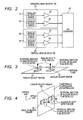
- FIG. 2 is a configuration diagram of a horizontal vibration detector and a vertical vibration detector according to the first to third embodiments.
- FIG. 3 is a view illustrating the arrangement of angular velocity sensors included in the horizontal vibration detector according to the first and second embodiments.
- FIG. 4 is a view illustrating the arrangement of angular velocity sensors included in the vertical vibration detector according to the first and second embodiments.
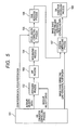
- FIG. 5 is a block diagram of an image shake correcting process according to the first embodiment.
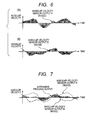
- FIG. 6 illustrates an image swinging amount generated when a single angular velocity sensor is used.
- FIG. 7 illustrates the image swinging amount after an averaging process according to the first embodiment is performed.
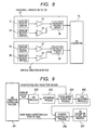
- FIG. 8 is a configuration diagram of the horizontal vibration detector and the vertical vibration detector when the averaging process is performed in an analog circuit.
- FIG. 9 is a block diagram of the image shake correcting process according to the first embodiment when the averaging process is performed in the analog circuit.
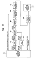
- FIG. 10 is a block diagram of an image shake correcting process according to the second embodiment.
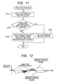
- FIG. 11 is a flowchart illustrating a selecting process according to the second embodiment.
- FIG. 12 is a graph illustrating an image swinging amount after the selecting process according to the second embodiment is performed.
- FIG. 13 is a flowchart illustrating the selecting process when three or more angular velocity sensors are used.
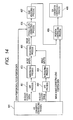
- FIG. 14 is a block diagram illustrating the image shake correcting process when outputs of integrating processes are subjected to the selecting process.
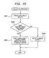
- FIG. 15 is a flowchart of the selecting process to be performed on the outputs of the integrating processes.
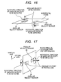
- FIG. 16 is a view illustrating the arrangement of angular velocity sensors included in the horizontal vibration detector according to the third embodiment.
- FIG. 17 is a view illustrating the arrangement of angular velocity sensors included in the vertical vibration detector according to the third embodiment.
- FIG. 18 is a block diagram of an image shake correcting process according to the third embodiment.
- FIG. 19 illustrates an image swinging amount after a subtracting process according to the third embodiment is performed.
- FIG. 20 is a block diagram of the image shake correcting process when a selecting process according to the third embodiment is performed.
- FIG. 1 is a diagram illustrating a configuration of a zoom lens apparatus according to a first embodiment, to which an optical apparatus of the present invention can be applied.
- a focus lens unit 1 is capable of displacing an imaging position of a zoom lens apparatus 50 and is driven in an optical-axis direction by a motor 11. A position of the focus lens unit 1 is converted into a voltage by a position detector 12.
- a zoom lens unit 2 has a variable focal length and is driven in the optical-axis direction by a motor 13. A position of the zoom lens unit 2 is converted into a voltage by a position detector 14.
- An image shake correcting lens unit 3 for decentering an optical axis is driven in a horizontal direction in a plane perpendicular to the optical axis by a horizontal driving motor 16.
- the amount of horizontal movement of the image shake correcting lens unit 3 is converted into a voltage by a horizontal position detector 17.
- the image shake correcting lens unit 3 is also driven in a vertical direction in a plane perpendicular to the optical axis by a vertically driving motor 15.
- the amount of vertical movement of the image shake correcting lens unit 3 is converted into a voltage by a vertical position detector 18.
- a camera is located so that an optical axis thereof extends horizontally.
- the "horizontal direction” means the optical-axis direction when the camera is installed on a level floor or a transverse direction perpendicular to the optical axis
- a "vertical direction” means a longitudinal direction perpendicular to the optical axis for the camera.
- the horizontal and vertical directions change according to the position and location of the camera when the camera is placed at an angle or upside down.
- a horizontal vibration applied to the zoom lens apparatus 50 is detected by a horizontal vibration detector 19, whereas a vertical vibration applied to the zoom lens apparatus 50 is detected by a vertical vibration detector 20. As illustrated in FIG.
- the horizontal vibration detector 19 includes angular velocity sensors 31 and 32 and amplifiers 33 and 34, whereas the vertical vibration detector 20 includes angular velocity sensors 35 and 36 and amplifiers 37 and 38.
- the angle sensors 31 and 32 included in the horizontal vibration detector 19 are arranged as illustrated in FIG. 3 so as to respectively detect rotational angular velocities on a horizontal plane.
- the angular velocity sensors 31 and 32 are arranged so that the axial directions of the angular velocities to be detected are the same.
- the angular velocity sensors 31 and 32 used in this embodiment have the same sensitivity and phase retardation at a vibration frequency (hereinafter, "the same sensitivity and phase retardation” means that a difference in sensitivity is within the range of ⁇ 5% and a difference in phase retardation is within the range of ⁇ 5% to a vibration at a frequency of 1 to 10 Hz).
- the angular velocity sensors 35 and 36 included in the vertical vibration detector 20 are arranged as illustrated in FIG. 4 so as to respectively detect rotational angular velocities on a plane parallel to the optical axis and the vertical axis.
- the angular velocity sensors 35 and 36 are arranged so that the axial directions of the angular velocities to be detected are the same.
- the angular velocity sensors 35 and 36 used in this embodiment have the same sensitivity and phase retardation at the vibration frequency.
- a focus driving circuit 21 generates a signal for driving the motor 11, whereas a zoom driving circuit 22 generates a signal for driving the motor 13.
- An image shake correcting lens driving circuit 23 generates signals for driving the horizontal driving motor 16 and the vertically driving motor 15.
- An A/D converter 24 converts the input voltages into digital data and transmits the thus obtained digital data to a CPU 26.
- a D/A converter 25 converts the digital data input from the CPU 26 into voltages and outputs the voltages to the focus driving circuit 21, the zoom driving circuit 22 and the image shake correcting lens driving circuit 23.
- the CPU 26 generates controlling data for driving the motors 11 and 13, the vertically driving motor 15, and the horizontal driving motor 16 from the pieces of digital data input from the A/D converter 24 and transmits the controlling data to the D/A converter 25.
- FIG. 5 is a block diagram illustrating the image shake correcting process in the horizontal direction according the first embodiment.
- focus position data, zoom position data, angular velocity data A, angular velocity data B, and image shake correcting lens position data are obtained.
- the angular velocity data A corresponds to the angular velocity data obtained from the angular velocity sensor 31, whereas the angular velocity data B corresponds to the angular velocity data obtained from the angular velocity sensor 32.
- an averaging process 102 the pieces of angular velocity data A and B are subjected to an averaging process.
- the averaging process is not limited to that for obtaining the arithmetic mean as expressed by equation (1). Therefore, a geometric mean as expressed by the following equation (2) may also be used (only when the inputs x 1 and x 2 are positive values). Alternatively, other averaging processes may also be performed.
- x ⁇ x 1 ⁇ x 2
- a DC component of the obtained angular velocity data is removed.
- the vibration angular velocity data is converted into vibration angle data.
- the angular velocity data is subjected to the averaging process in this embodiment.
- the two pieces of angular velocity data may be first subjected to the integrating process individually and then subjected to the averaging process as the angle data.
- a focal length correcting process 105 an appropriate amount of movement of the image shake correcting lens for a vibration angle differs depending on the focal length of the zoom lens apparatus 50. Therefore, the vibration angle data is multiplied by a focal length correcting gain value to correct the amount of movement.
- the focal length correcting gain value is obtained from the zoom position data and the focus position data by using a lookup table which is prestored in the CPU 26.
- the results of the focal length correcting process 105 are multiplied by an adjustment gain value set at the time of initial adjustment to calculate image shake correcting lens position command data so that an image shake amount due to vibrations applied to the zoom lens apparatus 50 and a shake correcting amount obtained by the image shake correcting lens become equal to each other.
- image shake correcting lens horizontal controlling data for controlling the horizontal driving motor 16 is generated from the image shake correcting lens position command data calculated in the gain adjusting process 106 and image shake correcting lens horizontal position data obtained in the A/D converter controlling process 101. Then, in a D/A converter controlling process 108, the image shake correcting lens horizontal controlling data is transmitted to the D/A converter 25.
- An image shake correcting process in the vertical direction is substantially the same as that in the horizontal direction, and therefore the description thereof is herein omitted.
- FIG. 6 illustrates examples of output noises of the angular velocity sensors when no vibration is applied
- FIG. 7 illustrates the results obtained by performing the averaging process on the outputs of the two angular velocity sensors respectively illustrated in (A) and (B) of FIG. 6
- each of the angular velocity sensors outputs a minute angular velocity signal.
- a shaded area illustrated in FIGS. 6, and 7 corresponds to a value obtained by integrating the vibration angular velocity signals, specifically, a value recognized as the vibration angle, and also corresponds to a value indicating an image swinging amount when the image shake correcting process is performed.
- the image swinging amount is reduced by averaging the outputs of the two angular velocity sensors as performed in this embodiment in comparison with that in the case where only one angular velocity sensor is used.
- ⁇ x ⁇ 1 N ⁇ ⁇ ⁇ x 1 2 + ⁇ ⁇ x 1 2 + ⁇ + ⁇ ⁇ x N 2
- N is the number of angular velocity sensors
- ⁇ (x n ) is the standard deviation (value indicating a variation degree).
- the image swinging amount can be reduced by 2 -1/2 .
- the outputs of the two angular velocity sensors are subjected to the averaging process as in this embodiment.
- the image swinging amount generated when no vibration is applied can be reduced without degrading the image shake correcting performance.
- the number of the used angular velocity sensors is two in this embodiment, the number of angular velocity sensors is not limited to two. Three or more angular velocity sensors may be used. In this case, as the number of angular velocity sensors becomes larger, the image swinging amount is reduced more according to Formula (4).
- the signals of the two angular velocity sensors are subjected to the averaging process under digital signals in the CPU 26.
- the signals may be subjected to the averaging process under analog signals.
- the horizontal vibration detector 19 and the vertical vibration detector 20 are configured as illustrated in FIG. 8 .
- the image shake correcting process executed in the CPU 26 is performed as illustrated in FIG. 9 .
- the averaging process of the analog signals can be realized.
- simple adding circuits are used as averaging process circuits 39 and 40 of FIG. 8 .
- a halving operation is performed in the amplifiers 33, 34, 37, and 38 corresponding to the previous stage or in a gain adjusting process 205 illustrated in FIG. 9 .
- the configurations of the zoom lens apparatus 50 and the vibration detectors 19 and 20, and the arrangement of the angular velocity sensors 31, 32, 35, and 36 are the same as those illustrated in FIGS. 1 to 4 , which are described in the first embodiment. Therefore, the description thereof is herein omitted.
- FIG. 10 is a block diagram illustrating the image shake correcting process in the horizontal direction according to the second embodiment.
- an A/D converter controlling process 301 the focus position data, the zoom position data, the angular velocity data A, the angular velocity data B, and the image shake correcting lens position data are obtained.
- a DC component of the angular velocity data A is removed in a highpass filter (HPF) process 302, whereas a DC component of the angular velocity data B is removed in an HPF process 303.
- HPF highpass filter
- FIG. 11 is a flowchart illustrating the selecting process 304.
- Step S101 an angular velocity input A output from the HPF process 302 and an angular velocity input B output from the HPF process 303 are obtained.
- Step S102 whether or not the signs of the obtained two angular velocity inputs are the same, specifically, whether or not the directions of the angular velocities are the same is determined.
- Step S103 one of the two angular velocity inputs, whose absolute value is smaller than the other, is set as an angular velocity output.
- Step S104 the angular velocity output is set to zero.
- the angular velocity output selected in the process illustrated in the flowchart of FIG. 11 is input to an integrating process 305 illustrated in FIG. 10 .
- the integrating process 305, a focal length correcting process 306, a gain adjusting process 307, a position controlling process 308 and a D/A converter controlling process 309 are the same as the integrating process 104, the focal length correcting process 105, the gain adjusting process 106, the position controlling process 107 and the D/A converter controlling process 108 illustrated in FIG. 5 . Therefore, the description thereof is herein omitted.
- FIG. 12 illustrates the results obtained after the outputs of the two angular velocity sensors illustrated in FIG. 6 are subjected to the selecting process 304 when no vibration is applied.
- the image swinging amount is reduced by performing the selecting process on the outputs of the two angular velocity sensors as in this embodiment in comparison with that in the case where only one angular velocity sensor is used.
- a shaded area in FIG. 12 is further reduced as compared with that of the output of the averaging process in FIG. 7 . Therefore, it is understood that the amount of reduction in image swinging amount is larger than that achieved by the averaging process. This is because the output obtained by performing the process as illustrated in the flowchart of FIG. 11 on the outputs of arbitrary two angular velocity sensors always becomes smaller than the output of the averaging process.
- the two angular velocity sensors when a vibration is applied, the two angular velocity sensors generate outputs having the same frequency characteristics as is described above in the first embodiment. Therefore, even if the process illustrated in the flowchart of FIG. 11 is performed, an angular velocity sensor output with a lower sensitivity is merely output. Specifically, when the vibration is applied, the characteristics which are the same as those obtained in the case where a single angular velocity sensor is used can be obtained. Accordingly, the degradation of the image shake correcting performance according to the frequency does not occur.
- the outputs of the two angular velocity sensors are subjected to the selecting process as in this embodiment.
- the image swinging amount generated when no vibration is applied can be reduced without degrading the image shake correcting performance.
- the number of used angular velocity sensors is two.
- the number of angular velocity sensors is not limited to two and may be three or more as in the case of the first embodiment.
- the selecting process 304 can be realized as illustrated in FIG. 13 .
- the selecting process is performed on the angular velocity signals in this embodiment.
- the selecting process may also be performed on the angle signals obtained after integrating processes.
- the image shake correcting process performed in the CPU 26 is performed as illustrated in FIG. 14 .
- a selecting process 406 is performed as illustrated in the flowchart of FIG. 15 . In this manner, the selecting process performed on the angle signals can be realized.
- the configurations of the zoom lens apparatus 50 and the vibration detectors 19 and 20 are the same as those illustrated in FIGS. 1 and 2 , which are described in the first embodiment. Therefore, the description thereof is herein omitted.
- the angular velocity sensors 31 and 32 are arranged as illustrated in FIG. 16 so as to respectively detect rotational angular velocities on the horizontal plane.
- the axial directions of the angular velocities to be detected are set at 180 degrees, that is, opposite to each other.
- the angular velocity sensors 35 and 36 are arranged as illustrated in FIG. 17 so as to respectively detect the rotational angular velocities on the plane parallel to the optical axis and the vertical axis.
- the axial directions of the angular velocities to be detected are set at 180 degrees, that is, opposite to each other.
- FIG. 18 is a block diagram illustrating the image shake correcting process in the horizontal direction according to the third embodiment.
- an A/D converter controlling process 501 the focus position data, the zoom position data, the angular velocity data A, the angular velocity data B and the image shake correcting lens position data are obtained.
- a subtracting process 502 for the pieces of angular velocity data A and B, an output x ' is calculated from the inputs x 1 and x 2 based on the following equation.
- x ⁇ ⁇ ⁇ x 1 - x 2 2
- An HPF process 503, an integrating process 504, a focal length correcting process 505, a gain adjusting process 506, a position controlling process 507 and a D/A converter controlling process 508 are the same as the HPF process 103, the integrating process 104, the focal length correcting process 105, the gain adjusting process 106, the position controlling process 107 and the D/A converter controlling process 108 illustrated in FIG. 5 . Therefore, the description thereof is herein omitted.
- the outputs of the two angular velocity sensors are subjected to the subtracting process in this embodiment.
- the angular velocities in the rotational directions opposite to each other are detected. Therefore, the angular velocities are averaged in the process expressed by equation (5). Specifically, the same effects as those of the first embodiment are obtained. Further, noises in the same phase are cancelled by performing the subtracting process as expressed by equation (5). Therefore, when the amount of noises in the same phase is large due to a circuit configuration, the image swinging amount can be greatly reduced.
- FIG. 19 illustrates the comparison between the image swinging amount after the averaging process as described in the first embodiment is performed and the image swinging amount after the subtracting process described in this embodiment is performed when the amount of noises in the same phase is large.
- the effects of the subtracting process become greater when the amount of noises in the same phase is large.
- the same effects as those of the first embodiment can be obtained because substantially the same process as that of the first embodiment is performed.
- the selecting process as described in the second embodiment may be performed in place of the subtracting process.
- the image shake correcting process performed in the CPU 26 is as illustrated in FIG. 20 .
- the image shake correcting process is realized by inversing the sign of one of outputs of HPF processes 602 and 603 (in the case illustrated in FIG. 20 , the output of the HPF process 603) in a sign inversing process 604.
- the case where the camera is located so that the optical axis thereof extends in the horizontal direction has been described as an example.
- the angular velocity sensors 31 and 32 are provided on the horizontal plane to detect the rotational angular velocities on the horizontal plane.
- the angular velocity sensors 35 and 36 are provided on the plane parallel to the optical axis and the vertical axis so as to detect the rotational angular velocities on the plane parallel to the optical axis and the vertical axis.
- an optical apparatus including: an image shake correcting unit for canceling an image shake generated due to a vibration; at least two angular velocity sensors having axes for detecting an angular velocity, the axes being parallel to each other; a vibration angle computing unit for calculating a vibration angle output based on output of the at least two angular velocity sensors; and a driving unit for driving the image shake correcting unit according to the vibration angle calculated by the angle computing unit.
Landscapes
- Engineering & Computer Science (AREA)
- Multimedia (AREA)
- Signal Processing (AREA)
- Physics & Mathematics (AREA)
- General Physics & Mathematics (AREA)
- Adjustment Of Camera Lenses (AREA)
- Studio Devices (AREA)
Applications Claiming Priority (1)
| Application Number | Priority Date | Filing Date | Title |
|---|---|---|---|
| JP2010125856A JP5599039B2 (ja) | 2010-06-01 | 2010-06-01 | 像ブレ補正機能付き光学装置 |
Publications (2)
| Publication Number | Publication Date |
|---|---|
| EP2393279A1 EP2393279A1 (en) | 2011-12-07 |
| EP2393279B1 true EP2393279B1 (en) | 2014-09-17 |
Family
ID=44508695
Family Applications (1)
| Application Number | Title | Priority Date | Filing Date |
|---|---|---|---|
| EP11167395.0A Not-in-force EP2393279B1 (en) | 2010-06-01 | 2011-05-25 | Optical apparatus having image shake correcting function |
Country Status (4)
| Country | Link |
|---|---|
| US (1) | US8809757B2 (enExample) |
| EP (1) | EP2393279B1 (enExample) |
| JP (1) | JP5599039B2 (enExample) |
| CN (1) | CN102269912B (enExample) |
Families Citing this family (5)
| Publication number | Priority date | Publication date | Assignee | Title |
|---|---|---|---|---|
| JP5797570B2 (ja) * | 2012-01-19 | 2015-10-21 | Hoya株式会社 | 光学要素の位置制御装置 |
| KR101740538B1 (ko) * | 2016-05-30 | 2017-06-08 | (주)다음기술단 | 사이드 스캔 소나의 영상 흔들림 보정 방법 |
| JP6792467B2 (ja) * | 2017-01-30 | 2020-11-25 | Kyb株式会社 | 信号処理装置 |
| JP2018109776A (ja) * | 2018-02-15 | 2018-07-12 | 株式会社ニコン | ブレ補正装置 |
| WO2025182603A1 (ja) * | 2024-03-01 | 2025-09-04 | ソニーグループ株式会社 | 光検出装置 |
Family Cites Families (14)
| Publication number | Priority date | Publication date | Assignee | Title |
|---|---|---|---|---|
| US5790490A (en) * | 1996-05-10 | 1998-08-04 | Olympus Optical Co., Ltd. | Anti-shake camera |
| JP3363862B2 (ja) * | 1999-01-22 | 2003-01-08 | キヤノン株式会社 | ジャイロ、それを備えたカメラ、レンズ及び自動車 |
| JP4311013B2 (ja) * | 2002-12-25 | 2009-08-12 | 株式会社ニコン | ブレ補正カメラシステム及びブレ補正カメラ |
| JP2004301512A (ja) * | 2003-03-28 | 2004-10-28 | Denso Corp | 角速度センサ装置 |
| JP4487246B2 (ja) | 2004-05-11 | 2010-06-23 | フジノン株式会社 | 像振れ補正装置 |
| JP2006178192A (ja) * | 2004-12-22 | 2006-07-06 | Canon Inc | 撮像装置 |
| JP4586534B2 (ja) * | 2004-12-28 | 2010-11-24 | セイコーエプソン株式会社 | 撮像装置、手ブレ補正装置、携帯電話機および手ブレ補正方法 |
| JP2006292845A (ja) | 2005-04-06 | 2006-10-26 | Canon Inc | 撮像装置 |
| JP2007127754A (ja) * | 2005-11-02 | 2007-05-24 | Nikon Corp | 像振れ補正装置、光学装置、交換レンズ、及びカメラシステム |
| JP2007164040A (ja) * | 2005-12-16 | 2007-06-28 | Nikon Corp | 像振れ補正装置 |
| JP2009008936A (ja) * | 2007-06-28 | 2009-01-15 | Ricoh Co Ltd | 撮像装置 |
| JP4807855B2 (ja) * | 2007-07-31 | 2011-11-02 | キヤノンマーケティングジャパン株式会社 | 防振装置および防振方法およびプログラム |
| WO2009060626A1 (ja) * | 2007-11-09 | 2009-05-14 | Panasonic Corporation | カメラ |
| JP2009270921A (ja) * | 2008-05-07 | 2009-11-19 | Fujitsu Media Device Kk | 角速度センサ |
-
2010
- 2010-06-01 JP JP2010125856A patent/JP5599039B2/ja not_active Expired - Fee Related
-
2011
- 2011-05-25 EP EP11167395.0A patent/EP2393279B1/en not_active Not-in-force
- 2011-05-27 CN CN201110139330.5A patent/CN102269912B/zh not_active Expired - Fee Related
- 2011-05-27 US US13/117,735 patent/US8809757B2/en not_active Expired - Fee Related
Also Published As
| Publication number | Publication date |
|---|---|
| EP2393279A1 (en) | 2011-12-07 |
| JP5599039B2 (ja) | 2014-10-01 |
| CN102269912A (zh) | 2011-12-07 |
| JP2011253004A (ja) | 2011-12-15 |
| US20110292510A1 (en) | 2011-12-01 |
| US8809757B2 (en) | 2014-08-19 |
| CN102269912B (zh) | 2014-08-13 |
Similar Documents
| Publication | Publication Date | Title |
|---|---|---|
| JP5111306B2 (ja) | 像ブレ補正機能を有する光学機器及びその制御方法 | |
| US8150250B2 (en) | Camera body and camera system including the same | |
| JP6614810B2 (ja) | ブレ補正装置、撮像装置、ブレ補正方法 | |
| US8811809B2 (en) | Image stabilization apparatus, control method therefor, optical apparatus and imaging apparatus | |
| JP4789614B2 (ja) | 防振制御装置およびその制御方法 | |
| EP2393279B1 (en) | Optical apparatus having image shake correcting function | |
| JP5237622B2 (ja) | 振動補正制御回路及びそれを備えた撮像装置 | |
| JP2006285040A (ja) | 像振れ補正装置 | |
| JP2011137996A (ja) | レンズ装置 | |
| JP2012128356A (ja) | ブレ補正装置及び光学機器 | |
| EP1713259B1 (en) | Photographing system | |
| JP2005257919A (ja) | 像振れ補正装置 | |
| US10911688B2 (en) | Control apparatus, imaging apparatus, and storage medium | |
| JP4305723B2 (ja) | 像振れ補正装置 | |
| JPH112852A (ja) | 光学装置の手振れ補正制御装置及び振れ補正機能付きカメラ | |
| JP2013178320A (ja) | 手ぶれ抑制機能付きカメラモジュールおよびその製造方法、電子情報機器 | |
| JP2012237884A (ja) | ブレ補正装置及び光学機器 | |
| JP2006003645A (ja) | 像振れ補正装置 | |
| JP4760175B2 (ja) | 像振れ補正装置 | |
| JP2014041230A (ja) | 像ブレ補正機能を有する光学機器及びその制御方法 | |
| JP2010230916A (ja) | ブレ補正装置および光学機器 | |
| JP5163556B2 (ja) | 手ぶれ補正装置 | |
| KR101575097B1 (ko) | 손떨림 보정 기능을 갖는 이미지 신호 처리기 | |
| JP2012208210A (ja) | 画像ぶれ補正装置 | |
| JP2006259567A (ja) | 像振れ補正装置 |
Legal Events
| Date | Code | Title | Description |
|---|---|---|---|
| AK | Designated contracting states |
Kind code of ref document: A1 Designated state(s): AL AT BE BG CH CY CZ DE DK EE ES FI FR GB GR HR HU IE IS IT LI LT LU LV MC MK MT NL NO PL PT RO RS SE SI SK SM TR |
|
| AX | Request for extension of the european patent |
Extension state: BA ME |
|
| PUAI | Public reference made under article 153(3) epc to a published international application that has entered the european phase |
Free format text: ORIGINAL CODE: 0009012 |
|
| 17P | Request for examination filed |
Effective date: 20120608 |
|
| 17Q | First examination report despatched |
Effective date: 20120824 |
|
| REG | Reference to a national code |
Ref country code: DE Ref legal event code: R079 Ref document number: 602011009911 Country of ref document: DE Free format text: PREVIOUS MAIN CLASS: H04N0005232000 Ipc: G03B0005020000 |
|
| GRAP | Despatch of communication of intention to grant a patent |
Free format text: ORIGINAL CODE: EPIDOSNIGR1 |
|
| RIC1 | Information provided on ipc code assigned before grant |
Ipc: G03B 5/02 20060101AFI20140326BHEP Ipc: H04N 5/232 20060101ALI20140326BHEP |
|
| INTG | Intention to grant announced |
Effective date: 20140409 |
|
| GRAS | Grant fee paid |
Free format text: ORIGINAL CODE: EPIDOSNIGR3 |
|
| GRAA | (expected) grant |
Free format text: ORIGINAL CODE: 0009210 |
|
| AK | Designated contracting states |
Kind code of ref document: B1 Designated state(s): AL AT BE BG CH CY CZ DE DK EE ES FI FR GB GR HR HU IE IS IT LI LT LU LV MC MK MT NL NO PL PT RO RS SE SI SK SM TR |
|
| REG | Reference to a national code |
Ref country code: GB Ref legal event code: FG4D |
|
| REG | Reference to a national code |
Ref country code: CH Ref legal event code: EP |
|
| REG | Reference to a national code |
Ref country code: IE Ref legal event code: FG4D |
|
| REG | Reference to a national code |
Ref country code: AT Ref legal event code: REF Ref document number: 687950 Country of ref document: AT Kind code of ref document: T Effective date: 20141015 |
|
| REG | Reference to a national code |
Ref country code: DE Ref legal event code: R096 Ref document number: 602011009911 Country of ref document: DE Effective date: 20141030 |
|
| REG | Reference to a national code |
Ref country code: DE Ref legal event code: R082 Ref document number: 602011009911 Country of ref document: DE Representative=s name: TBK, DE |
|
| PG25 | Lapsed in a contracting state [announced via postgrant information from national office to epo] |
Ref country code: SE Free format text: LAPSE BECAUSE OF FAILURE TO SUBMIT A TRANSLATION OF THE DESCRIPTION OR TO PAY THE FEE WITHIN THE PRESCRIBED TIME-LIMIT Effective date: 20140917 Ref country code: NO Free format text: LAPSE BECAUSE OF FAILURE TO SUBMIT A TRANSLATION OF THE DESCRIPTION OR TO PAY THE FEE WITHIN THE PRESCRIBED TIME-LIMIT Effective date: 20141217 Ref country code: LT Free format text: LAPSE BECAUSE OF FAILURE TO SUBMIT A TRANSLATION OF THE DESCRIPTION OR TO PAY THE FEE WITHIN THE PRESCRIBED TIME-LIMIT Effective date: 20140917 Ref country code: FI Free format text: LAPSE BECAUSE OF FAILURE TO SUBMIT A TRANSLATION OF THE DESCRIPTION OR TO PAY THE FEE WITHIN THE PRESCRIBED TIME-LIMIT Effective date: 20140917 Ref country code: GR Free format text: LAPSE BECAUSE OF FAILURE TO SUBMIT A TRANSLATION OF THE DESCRIPTION OR TO PAY THE FEE WITHIN THE PRESCRIBED TIME-LIMIT Effective date: 20141218 |
|
| REG | Reference to a national code |
Ref country code: NL Ref legal event code: VDEP Effective date: 20140917 |
|
| REG | Reference to a national code |
Ref country code: LT Ref legal event code: MG4D |
|
| PG25 | Lapsed in a contracting state [announced via postgrant information from national office to epo] |
Ref country code: CY Free format text: LAPSE BECAUSE OF FAILURE TO SUBMIT A TRANSLATION OF THE DESCRIPTION OR TO PAY THE FEE WITHIN THE PRESCRIBED TIME-LIMIT Effective date: 20140917 Ref country code: LV Free format text: LAPSE BECAUSE OF FAILURE TO SUBMIT A TRANSLATION OF THE DESCRIPTION OR TO PAY THE FEE WITHIN THE PRESCRIBED TIME-LIMIT Effective date: 20140917 Ref country code: RS Free format text: LAPSE BECAUSE OF FAILURE TO SUBMIT A TRANSLATION OF THE DESCRIPTION OR TO PAY THE FEE WITHIN THE PRESCRIBED TIME-LIMIT Effective date: 20140917 Ref country code: HR Free format text: LAPSE BECAUSE OF FAILURE TO SUBMIT A TRANSLATION OF THE DESCRIPTION OR TO PAY THE FEE WITHIN THE PRESCRIBED TIME-LIMIT Effective date: 20140917 |
|
| REG | Reference to a national code |
Ref country code: AT Ref legal event code: MK05 Ref document number: 687950 Country of ref document: AT Kind code of ref document: T Effective date: 20140917 |
|
| PG25 | Lapsed in a contracting state [announced via postgrant information from national office to epo] |
Ref country code: NL Free format text: LAPSE BECAUSE OF FAILURE TO SUBMIT A TRANSLATION OF THE DESCRIPTION OR TO PAY THE FEE WITHIN THE PRESCRIBED TIME-LIMIT Effective date: 20140917 |
|
| PG25 | Lapsed in a contracting state [announced via postgrant information from national office to epo] |
Ref country code: IS Free format text: LAPSE BECAUSE OF FAILURE TO SUBMIT A TRANSLATION OF THE DESCRIPTION OR TO PAY THE FEE WITHIN THE PRESCRIBED TIME-LIMIT Effective date: 20150117 Ref country code: CZ Free format text: LAPSE BECAUSE OF FAILURE TO SUBMIT A TRANSLATION OF THE DESCRIPTION OR TO PAY THE FEE WITHIN THE PRESCRIBED TIME-LIMIT Effective date: 20140917 Ref country code: RO Free format text: LAPSE BECAUSE OF FAILURE TO SUBMIT A TRANSLATION OF THE DESCRIPTION OR TO PAY THE FEE WITHIN THE PRESCRIBED TIME-LIMIT Effective date: 20140917 Ref country code: PT Free format text: LAPSE BECAUSE OF FAILURE TO SUBMIT A TRANSLATION OF THE DESCRIPTION OR TO PAY THE FEE WITHIN THE PRESCRIBED TIME-LIMIT Effective date: 20150119 Ref country code: EE Free format text: LAPSE BECAUSE OF FAILURE TO SUBMIT A TRANSLATION OF THE DESCRIPTION OR TO PAY THE FEE WITHIN THE PRESCRIBED TIME-LIMIT Effective date: 20140917 Ref country code: ES Free format text: LAPSE BECAUSE OF FAILURE TO SUBMIT A TRANSLATION OF THE DESCRIPTION OR TO PAY THE FEE WITHIN THE PRESCRIBED TIME-LIMIT Effective date: 20140917 Ref country code: SK Free format text: LAPSE BECAUSE OF FAILURE TO SUBMIT A TRANSLATION OF THE DESCRIPTION OR TO PAY THE FEE WITHIN THE PRESCRIBED TIME-LIMIT Effective date: 20140917 |
|
| PG25 | Lapsed in a contracting state [announced via postgrant information from national office to epo] |
Ref country code: AT Free format text: LAPSE BECAUSE OF FAILURE TO SUBMIT A TRANSLATION OF THE DESCRIPTION OR TO PAY THE FEE WITHIN THE PRESCRIBED TIME-LIMIT Effective date: 20140917 Ref country code: PL Free format text: LAPSE BECAUSE OF FAILURE TO SUBMIT A TRANSLATION OF THE DESCRIPTION OR TO PAY THE FEE WITHIN THE PRESCRIBED TIME-LIMIT Effective date: 20140917 |
|
| REG | Reference to a national code |
Ref country code: DE Ref legal event code: R097 Ref document number: 602011009911 Country of ref document: DE |
|
| PLBE | No opposition filed within time limit |
Free format text: ORIGINAL CODE: 0009261 |
|
| STAA | Information on the status of an ep patent application or granted ep patent |
Free format text: STATUS: NO OPPOSITION FILED WITHIN TIME LIMIT |
|
| PG25 | Lapsed in a contracting state [announced via postgrant information from national office to epo] |
Ref country code: DK Free format text: LAPSE BECAUSE OF FAILURE TO SUBMIT A TRANSLATION OF THE DESCRIPTION OR TO PAY THE FEE WITHIN THE PRESCRIBED TIME-LIMIT Effective date: 20140917 |
|
| 26N | No opposition filed |
Effective date: 20150618 |
|
| PG25 | Lapsed in a contracting state [announced via postgrant information from national office to epo] |
Ref country code: IT Free format text: LAPSE BECAUSE OF FAILURE TO SUBMIT A TRANSLATION OF THE DESCRIPTION OR TO PAY THE FEE WITHIN THE PRESCRIBED TIME-LIMIT Effective date: 20140917 |
|
| PG25 | Lapsed in a contracting state [announced via postgrant information from national office to epo] |
Ref country code: SI Free format text: LAPSE BECAUSE OF FAILURE TO SUBMIT A TRANSLATION OF THE DESCRIPTION OR TO PAY THE FEE WITHIN THE PRESCRIBED TIME-LIMIT Effective date: 20140917 |
|
| REG | Reference to a national code |
Ref country code: CH Ref legal event code: PL |
|
| GBPC | Gb: european patent ceased through non-payment of renewal fee |
Effective date: 20150525 |
|
| PG25 | Lapsed in a contracting state [announced via postgrant information from national office to epo] |
Ref country code: LU Free format text: LAPSE BECAUSE OF FAILURE TO SUBMIT A TRANSLATION OF THE DESCRIPTION OR TO PAY THE FEE WITHIN THE PRESCRIBED TIME-LIMIT Effective date: 20150525 Ref country code: LI Free format text: LAPSE BECAUSE OF NON-PAYMENT OF DUE FEES Effective date: 20150531 Ref country code: CH Free format text: LAPSE BECAUSE OF NON-PAYMENT OF DUE FEES Effective date: 20150531 Ref country code: MC Free format text: LAPSE BECAUSE OF FAILURE TO SUBMIT A TRANSLATION OF THE DESCRIPTION OR TO PAY THE FEE WITHIN THE PRESCRIBED TIME-LIMIT Effective date: 20140917 |
|
| REG | Reference to a national code |
Ref country code: IE Ref legal event code: MM4A |
|
| REG | Reference to a national code |
Ref country code: FR Ref legal event code: ST Effective date: 20160129 |
|
| PG25 | Lapsed in a contracting state [announced via postgrant information from national office to epo] |
Ref country code: GB Free format text: LAPSE BECAUSE OF NON-PAYMENT OF DUE FEES Effective date: 20150525 Ref country code: IE Free format text: LAPSE BECAUSE OF NON-PAYMENT OF DUE FEES Effective date: 20150525 |
|
| PG25 | Lapsed in a contracting state [announced via postgrant information from national office to epo] |
Ref country code: FR Free format text: LAPSE BECAUSE OF NON-PAYMENT OF DUE FEES Effective date: 20150601 |
|
| PG25 | Lapsed in a contracting state [announced via postgrant information from national office to epo] |
Ref country code: MT Free format text: LAPSE BECAUSE OF FAILURE TO SUBMIT A TRANSLATION OF THE DESCRIPTION OR TO PAY THE FEE WITHIN THE PRESCRIBED TIME-LIMIT Effective date: 20140917 |
|
| PG25 | Lapsed in a contracting state [announced via postgrant information from national office to epo] |
Ref country code: BG Free format text: LAPSE BECAUSE OF FAILURE TO SUBMIT A TRANSLATION OF THE DESCRIPTION OR TO PAY THE FEE WITHIN THE PRESCRIBED TIME-LIMIT Effective date: 20140917 Ref country code: SM Free format text: LAPSE BECAUSE OF FAILURE TO SUBMIT A TRANSLATION OF THE DESCRIPTION OR TO PAY THE FEE WITHIN THE PRESCRIBED TIME-LIMIT Effective date: 20140917 Ref country code: HU Free format text: LAPSE BECAUSE OF FAILURE TO SUBMIT A TRANSLATION OF THE DESCRIPTION OR TO PAY THE FEE WITHIN THE PRESCRIBED TIME-LIMIT; INVALID AB INITIO Effective date: 20110525 |
|
| PG25 | Lapsed in a contracting state [announced via postgrant information from national office to epo] |
Ref country code: TR Free format text: LAPSE BECAUSE OF FAILURE TO SUBMIT A TRANSLATION OF THE DESCRIPTION OR TO PAY THE FEE WITHIN THE PRESCRIBED TIME-LIMIT Effective date: 20140917 |
|
| PG25 | Lapsed in a contracting state [announced via postgrant information from national office to epo] |
Ref country code: BE Free format text: LAPSE BECAUSE OF FAILURE TO SUBMIT A TRANSLATION OF THE DESCRIPTION OR TO PAY THE FEE WITHIN THE PRESCRIBED TIME-LIMIT Effective date: 20140917 |
|
| PG25 | Lapsed in a contracting state [announced via postgrant information from national office to epo] |
Ref country code: MK Free format text: LAPSE BECAUSE OF FAILURE TO SUBMIT A TRANSLATION OF THE DESCRIPTION OR TO PAY THE FEE WITHIN THE PRESCRIBED TIME-LIMIT Effective date: 20140917 |
|
| PG25 | Lapsed in a contracting state [announced via postgrant information from national office to epo] |
Ref country code: AL Free format text: LAPSE BECAUSE OF FAILURE TO SUBMIT A TRANSLATION OF THE DESCRIPTION OR TO PAY THE FEE WITHIN THE PRESCRIBED TIME-LIMIT Effective date: 20140917 |
|
| PGFP | Annual fee paid to national office [announced via postgrant information from national office to epo] |
Ref country code: DE Payment date: 20200728 Year of fee payment: 10 |
|
| REG | Reference to a national code |
Ref country code: DE Ref legal event code: R119 Ref document number: 602011009911 Country of ref document: DE |
|
| PG25 | Lapsed in a contracting state [announced via postgrant information from national office to epo] |
Ref country code: DE Free format text: LAPSE BECAUSE OF NON-PAYMENT OF DUE FEES Effective date: 20211201 |