EP2390218B1 - Seilhaltevorrichtung für einen Aufzug - Google Patents
Seilhaltevorrichtung für einen Aufzug Download PDFInfo
- Publication number
- EP2390218B1 EP2390218B1 EP11171308A EP11171308A EP2390218B1 EP 2390218 B1 EP2390218 B1 EP 2390218B1 EP 11171308 A EP11171308 A EP 11171308A EP 11171308 A EP11171308 A EP 11171308A EP 2390218 B1 EP2390218 B1 EP 2390218B1
- Authority
- EP
- European Patent Office
- Prior art keywords
- guide rail
- column
- support bodies
- rope
- rope supporting
- Prior art date
- Legal status (The legal status is an assumption and is not a legal conclusion. Google has not performed a legal analysis and makes no representation as to the accuracy of the status listed.)
- Expired - Lifetime
Links
Images


Classifications
-
- B—PERFORMING OPERATIONS; TRANSPORTING
- B66—HOISTING; LIFTING; HAULING
- B66B—ELEVATORS; ESCALATORS OR MOVING WALKWAYS
- B66B7/00—Other common features of elevators
- B66B7/02—Guideways; Guides
-
- B—PERFORMING OPERATIONS; TRANSPORTING
- B66—HOISTING; LIFTING; HAULING
- B66B—ELEVATORS; ESCALATORS OR MOVING WALKWAYS
- B66B7/00—Other common features of elevators
- B66B7/02—Guideways; Guides
- B66B7/023—Mounting means therefor
- B66B7/027—Mounting means therefor for mounting auxiliary devices
-
- B—PERFORMING OPERATIONS; TRANSPORTING
- B66—HOISTING; LIFTING; HAULING
- B66B—ELEVATORS; ESCALATORS OR MOVING WALKWAYS
- B66B11/00—Main component parts of lifts in, or associated with, buildings or other structures
- B66B11/0065—Roping
- B66B11/008—Roping with hoisting rope or cable operated by frictional engagement with a winding drum or sheave
-
- B—PERFORMING OPERATIONS; TRANSPORTING
- B66—HOISTING; LIFTING; HAULING
- B66B—ELEVATORS; ESCALATORS OR MOVING WALKWAYS
- B66B7/00—Other common features of elevators
- B66B7/06—Arrangements of ropes or cables
-
- B—PERFORMING OPERATIONS; TRANSPORTING
- B66—HOISTING; LIFTING; HAULING
- B66B—ELEVATORS; ESCALATORS OR MOVING WALKWAYS
- B66B7/00—Other common features of elevators
- B66B7/06—Arrangements of ropes or cables
- B66B7/08—Arrangements of ropes or cables for connection to the cars or cages, e.g. couplings
Definitions
- the present invention relates to a rope supporting apparatus for at elevator for supporting ropes to suspending a car and/or a counterweight within a hoist way.
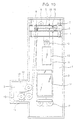
- Fig. 10 is a strucrural view snowing an example of a conventional elevator.
- a hoist way 1 is formed by a steel structure 2.
- a machine room 3 is formed in the vicinity of a bottom portion of the hoist way 1.
- Rope holding beams 6 and 7 are mounted on beams 4 and 5 positioned at the upper portion of the steel structure 2.
- Rotatable return pulieys a and 9 are provided on the rope holding beams 6 and 7.
- a hoisting machine 10 having a sneave 11 is disposed in the machine room 3. Also, rotatable defector sheaves 12 and 13 are provided in the machine room 3.
- a rope 16 for suspending a car 14 and 3 counterweight 15. within the hoist way 1 is laid around the sheave 11 and directed by the return pulleys 8 and 9 through the deflection sheaves 12 and 13 and is caused to pass below suspension shaves 17 and 16 provided on the car 14 and the counterweight 15. Both end portions of the rope 16 are fixed to the rope holding beams 6 and 7 through fastening members 19, respectively.
- the sheave 11 is rotated forward or reversely by a drive force of the hoisting machine 10 so that the car 14 and the counterweight 15 are alternatively moved up and down within the hoist way 1.
- the hoist way 1 is formed by the steel structure 2.
- concave/convex portions for supporting both end portions of the rope holding beams are provided on the walls of the hoist way. Then, both end portions or the rope holding beams are fixed to shoulder portions of the concave/convex portions.
- Hatsumei Kyokai Technical Disclosure Bulletin No. 9C-9351 discloses a rope end fixing device in which a member to which the end portions of a rope are fixed may be mounted on a guide rail for guiding the vertical movement of the car and/or counterweight.
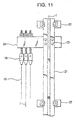
- Fig. 11 is a front view showing an example of a conventional rope end fixing device.
- a guide rail 21 for guiding the vertical movement of the car or the counterweight is fixed in place through a plurality of brackets 22.
- a rope end fixing member 24 is fixed through, for example, a plurality of support bodies 23 having bolt-and-nut assemblies. End portions of a plurality of ropes 16 are fixed to the rope end fixing member 24 through fastening members, respectively.
- WO 96/09978 A1 refers to an arrangement for fixing an elevator rope. According to the disclosed configuration, at least one end of the elevator rope is fixed to a guide rail of the elevator, and the whole elevator may be suspended by its ropes so that all vertical forces are transmitted by the guide rail to the bottom of the shaft.
- an object of the present invention is to provide a rope supporting apparatus for an elevator which is able to reduce any bending moment that applied to a guide rail.
- Fig. 1 is a front view showing a rope supporting apparatus for an elevator in accordance with this embodiment of the invention
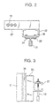
- Fig. 2 is a cross-sectional view taken along the fine II-II of Fig. 1
- Fig. 3 is a right side elevational view showing an essential portion of the apparatus shown in Fig. 1 .
- a guide rail 31 for guiding the vertical movement of a car (not shown) or a counterweight (not shown) is fixed in place through a plurality of rail brackets 32.
- a column-like body 33 extending along the guide rail 31 is mounted on the guide rail 31 through a plurality of support bodies 34 provided at both end portions thereof.
- the support bodies 34 have bolts 35 passing through the guide rail 31 and the column-like body 33 and nuts 36 threadably engaged with the bolts 35.
- the column-like body 33 has a higher bending strength than that of the guide rail.
- the working center of tension applied to the ropes 16 does not correspond to the center axis C of the guide rail 33 so that the bending moment caused by the eccentric load is applied to the column-like body 33 through the rope end fixing member 37.
- This bending moment is transmitted to the guide rail 31 through support bodies 34.
- the support bodies 34 at both upper and lower end portions of the column-like body 33 are arranged with a sufficient distance therebetween, the pivot reactive force, which is the load in the direction perpendicular to the rail center axis C generated in the support bodies 34 (in the right and left directions in Fig. 1 ) becomes smaller, and the bending moment applied to the guide rail 31 by the pivot reactive force becomes smaller than the bending moment applied to the colum-like body 33.
- the bending moment applied to the column-like body 33 is substantially the same as the bending moment applied to the guide rail 21 in the conventional apparatus shown in Fig. 11 .
- the bending strength of the column-like body 33 is made higher than the bending strength of only the guide rail 31 so that sufficient strength of the rope supporting apparatus may be maintained. Accordingly, it is unnecessary to enlarge the guide rail 21 and it is possible to increase the distance between the rail brackets 32. Furthermore, it is also possible to increase the tension applied to the rope ends.
- the support bodies 34 which pass through the guide rail 31 and the column-like body 33 are used, it is possible to facilitate the mounting of the column-like body 33 onto the guide rail 31 to thereby reduce manufacturing costs and shorten instalation time.
- the support bodies 34 are disposed in the vicinity of the rail brackets 32 so that the distortion is prevented from being generated in the guide rail 31 by the load from the support bodies 34.
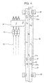
- Fig. 4 is a front view showing a rope supporting apparatus for an elevator in accordance with embodiment of the invention.
- a plurality of first oblang holes 31 a extending in parallel with the center axis C and a plurality of second oblong holes 31b extending perpendicular to the center axis C are provided in the guide rail 31.
- a plurality of first support bodies 41 for mounting the column-like body 33 onto the guide rail 31 through the first oblong holes 31 a are provided at both upper and lower end portions of the column-like body 33. These first support bodies 41 serve to transmit to the guide rail 31 only the load in the perpendicular direction to the center axis C of the guide rail 31.
- a plurality of second support bodies 42 for mounting the column-like body 33 on the guide rail 31 through the second oblong holes 31b are provided at the lower end portion of the column-like body 33. These second support bodies 42 serve to transmit to the guide rail 31 only the load parallel to the center axis C of the guide rail 31.
- the other structures are the same as those of embodiment 1.
- the position where the maximum bending moment is applied is displaced from the position where the compression load is applied so that the combined stress generated in the guide rail 31 by the bending moment and the compression load may be reduced.
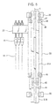
- Fig. 5 is a front view showing a rope supporting apparatus for an elevator in accordance with embodiment 3 of the present invention
- guide rails 31A and 31 B adjacent to each other in the vertical direction are connected and fixed to each other by a rail joint body 43.
- the rail joint body 43 is fixed to a lower end portion of the guide rail 31A and an upper end portion of the guide rail 31B by a plurality of bolts 44.
- the lower end portion of the column-like body 33 is in contact with the upper end portion of the rail joint body 43.
- the column-like body 33 is mounted on the guide rail 31 by a plurality of support bodies 45 arranged at both upper and lower end portions thereof.
- the support bodies 45 have rail clips 46 for clamping the guide rail 31 in cooperation with the column-like body 33 and bolts 47 for fastening the rail clips 46.
- the support bodies 45 transmit to the guide rail 31 only the load in the direction perpendicular to the center axis C of the guide rail 31.
- the other structures are the same as those of embodiment 1.
- the position where the maximum bending moment is applied is displaced from the position where the compression load is applied so that the combined stress generated in the guide rail 31 by the bending moment and the compression load may be reduced.
- Fig. 6 is a front view showing a rope supporting apparatus in accordance with embodiment of the present invention.
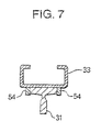
- Fig. 7 is a cross-sectional view taken along the line VII-VII of Fig. 6 .
- a support member 51 for supporting only the load from the column-like body 33 in a direction parallel to the center axis C is fixed to the guide rail 31 by a plurality of bolts 52.
- a lower end portion of the column-like body 33 is in contact with an upper end portion of the support member 51.
- the column-like body 33 is mounted on the guide rail 31 by a plurality of rail clips 53.
- a plurality of pivot members 54 are fixed to both upper and lower end portions of the column-like body 33, respectively, as support bodies which are brought into contact with both side portions of the guide rail 31.
- the pivot members 54 transmit only the load from the column-like body 33 in the direction perpendicular to the center axis C to the guide rail 31.
- the pivot members 54 are the components for transmitting the load to the guide rail 31 in the direction perpendicular to the center axis C, whereas the rail clips 53 prevent the column-like body 33 from being displaced upwardly in Fig. 7 from the guide rail 31.
- the other structures are the same as those of embodiment 1.
- the pivot member 54 which can be freely designed in terms of their cross-sectional area and shape, are fixed to the column-like body 33 in order to transmit 33 to the guide rail 31 only the load in the direction parallel to the center axis C. Accordingly, it is possible to keep the strength of the pivot members 54 at a sufficient level.
- the position where the maximum banding moment is applied is displaced from the position where the compression load is applied so that the combined stress generated in the guide rail 31 by the bending moment and the compression load may be reduced.
- Fig. 8 is a front view showing a rope supporting apparatus in accordance with this embodiment of the present invention.
- the rope end fixing member 37 to which the end portions of the ropes 16 are fixed is shown as the rope supporting member.
- a return pulley support member 55 is fixed to the column-like body 33 as a rope support member.
- a return pulley 56 is mounted on the return pulley support member 55, and a rope 16 is wound around the rectum pulley.
- Fig. 2 shows an example in which the rope end fixing member 37 is mounted on an opposite surface (back surface) of the guide rail mounting surface of the column-like body 33
- Fig. 9 it is also possible to mount the rope end fixing member 37 on the side surface of the column-like body 33 as shown in Fig. 9 .
- the rope end fixing member 37 is mounted at the upper portion of the column-like body 33, it is possible to mount the rope end fixing member 37 at a central portion or lower portion, along the height of the column-like body 33.
- the cross-sectional shape of the column-like body 33 is substantially in the form of a C, but the shape thereof is not limited thereto. If is also possible for it to have, for example, a cylindrical shape. In addition, it is also possible for the column-like body 33 to be a soiid member, but it is advantageous to use a hollow member in view of weight reduction.
- the rope end fixing member 37 is fixed to the column-like body 33 by welding, but it is possible to fix it with bolts or the like. Also, It is possible to provide the rope end fixing member at the column-like body by, for example, bending a steel member in a one-piece manner.
- the column-fike body 33 is mounted on the guide rail 31 having a T-shaped cross section.
- the type of guide rail is not limited thereto. For instance, it is possible to use a guide rail which is formed by bending a steel plate.
- the support bodies 34 having bolts are used but, , the column-like body can be welded to the guide rail for instance and this welded portion may be used as the pivot member.
- the support member 51 is fixed to the guide rail by the bolts 52, it may also be fixed by welding.
Landscapes
- Engineering & Computer Science (AREA)
- Civil Engineering (AREA)
- Mechanical Engineering (AREA)
- Structural Engineering (AREA)
- Lift-Guide Devices, And Elevator Ropes And Cables (AREA)
Claims (14)
- Seillagervorrichtung für einen Aufzug mit:einem säulenähnlichen Körper (33), der sich entlang einer Führungsschiene erstreckt, die innerhalb eines Schachts eingebaut ist, und der an der Führungsschiene angebracht ist,einem Seillagerelement (37), das an dem säulenähnlichen Körper befestigt ist, um ein Seil (16) zu lagern, an dem eine Kabine und/oder ein Gegengewicht innerhalb des Schachts hängt, undmehreren Lagerkörpern, die zwischen dem säulenähnlichen Körper (33) und der Führungsschiene vorgesehen sind, um eine Last von dem säulenähnlichen Körper auf die Führungsschiene zu übertragen, wobeieine Spannung des Seils (16), die auf das Seillagerelement (37) aufzubringen ist, bezüglich einer Mittelachse der Führungsschiene exzentrisch ist,der säulenähnliche Körper (33) eine Last in der senkrechten Richtung zur Mittelachse der Führungsschiene und eine Last parallel zur Mittelachse der Führungsschiene empfängt,der säulenähnliche Körper (33) sich so erstreckt, dass die Lagerkörper mit einem hinreichenden Abstand zwischen ihnen in einer Richtung entlang der Führungsschiene angeordnet sind,der säulenähnliche Körper (33) einen oberen Endabschnitt und einen unteren Endabschnitt aufweist,die Lagerkörper an einer Seite des oberen Endabschnitts und an einer Seite des unteren Endabschnitts vorgesehen sind undein Anbringarm eines Geschwindigkeitsregulators in die oben beschriebene Seillagervorrichtung eingebaut ist.
- Seillagervorrichtung für einen Aufzug nach Anspruch 1, bei der das Seillagerelement (37) ein Seilendenbefestigungselement ist, an dem ein Endabschnitt des Seils befestigt ist.
- Seillagervorrichtung für einen Aufzug nach Anspruch 1, bei der das Seillagerelement (37) ein Rückführrollen-Lagerelement ist, an dem eine Rückführrolle, um die das Seil gewickelt ist, angebracht ist.
- Seillagervorrichtung für einen Aufzug nach Anspruch 1, bei der der säulenähnliche Körper eine höhere Biegefestigkeit als eine Biegefestigkeit der Führungsschiene aufweist.
- Seillagervorrichtung für einen Aufzug nach Anspruch 1, bei der die Lagerkörper durch die Führungsschiene und den säulenähnlichen Körper (33) hindurchtreten.
- Seillagervorrichtung für einen Aufzug nach Anspruch 1, bei der die Lagerkörper eine erste Gruppe an Lagerkörpern zum Übertragen einer Last auf die Führungsschiene nur in einer Richtung senkrecht zu einer Mittelachse der Führungsschiene und eine zweite Gruppe an Lagerkörpern zum Übertragen einer Last auf die Führungsschiene nur in einer Richtung parallel zur Mittelachse der Führungsschiene aufweisen, wobei insbesondere die ersten Lagerkörper Schienenklemmen zum Einklemmen der Führungsschiene zusammen mit dem säulenähnlichen Körper und den Schienenklemmen aufweisen, und/oder die ersten Lagerkörper Schwenkelemente aufweisen, die an dem säulenähnlichen Körper so befestigt sind, dass sie in Kontakt mit beiden Seitenabschnitten der Führungsschiene sind.
- Seillagervorrichtung für einen Aufzug nach Anspruch 1, bei der die Lagerkörper auf die Führungsschiene eine Last nur in einer Richtung senkrecht zu einer Mittelachse der Führungsschiene übertragen und wobei ein unterer Endabschnitt eines säulenähnlichen Körpers in Kontakt mit einem Schienenverbindungselement zum Verbinden benachbarter Führungsschienen ist.
- Seillagervorrichtung für einen Aufzug nach Anspruch 7, bei der die Lagerkörper Schienenklemmen zum Einklemmen der Führungsschiene zusammen mit dem säulenähnlichen Körper aufweisen.
- Seillagervorrichtung für einen Aufzug nach Anspruch 7, bei der die Lagerkörper Schwenkelemente aufweisen, die an dem säulenähnlichen Körper so befestigt sind, dass sie in Kontakt mit beiden Seitenabschnitten der Führungsschiene sind.
- Seillagervorrichtung für einen Aufzug nach Anspruch 1, ferner mit einem Lagerelement, das an der Führungsschiene in Kontakt mit einem Endabschnitt des säulenähnlichen Körpers befestigt ist, um eine Last nur in einer Richtung parallel zu einer Mittelachse der Führungsschiene zu empfangen, wobei die Lagerkörper auf die Führungsschiene eine Last nur in einer Richtung senkrecht zu einer Mittelachse der Führungsschiene übertragen, wobei insbesondere die Lagerkörper Schienenklemmen zum Einklemmen der Führungsschiene zusammen mit dem Lagerkörper aufweisen und/oder die Lagerkörper Schwenkelemente befestigt an dem säulenähnlichen Körper aufweisen, um in Kontakt mit beiden Seitenabschnitten der Führungsschiene zu sein.
- Seillagervorrichtung für einen Aufzug nach Anspruch 1, bei der eine Abmessung des säulenähnlichen Körpers in einer Richtung entlang der Führungsschiene wesentlich größer ist als diejenige des Seillagerelements.
- Seillagervorrichtung für einen Aufzug nach Anspruch 1, bei der die Lagerkörper eine erste Gruppe an Lagerkörpern zum Übertragen einer Last auf die Führungsschiene nur in einer Richtung senkrecht zu einer Mittelachse der Führungsschiene mit Schienenklemmen zum Einklemmen der Führungsschiene zusammen mit dem säulenähnlichen Körper und den Schienenklemmen und eine zweite Gruppe an Lagerkörpern aufweisen, um eine Last nur in einer Richtung parallel zu einer Mittelachse der Führungsschiene aufzunehmen und um auf diese Führungsschiene eine Last nur in einer Richtung parallel zu einer Mittelachse der Führungsschiene zu übertragen, wobei die Schienenklemmen mit einem hinreichenden Abstand zwischen ihnen in der Richtung entlang der Führungsschiene angeordnet sind.
- Seillagervorrichtung für einen Aufzug nach Anspruch 5, bei der die Führungsschiene im Schacht durch mehrere Schienenklammern befestigt ist und die Lagerkörper in einer Nachbarschaft der Schienenklammern vorgesehen sind.
- Seillagervorrichtung für einen Aufzug nach Anspruch 1, bei der der säulenähnliche Körper an einer Rückoberfläche der Führungsschiene vorgesehen ist.
Applications Claiming Priority (3)
| Application Number | Priority Date | Filing Date | Title |
|---|---|---|---|
| EP09172648.9A EP2145851B1 (de) | 1998-03-23 | 1998-03-23 | Seilhaltevorrichtung für einen Aufzug |
| PCT/JP1998/001245 WO1999048789A1 (en) | 1998-03-23 | 1998-03-23 | Rope support device for elevator |
| EP98909820A EP0995712B1 (de) | 1998-03-23 | 1998-03-23 | Haltungsvorrichtung für aufzugsseile |
Related Parent Applications (3)
| Application Number | Title | Priority Date | Filing Date |
|---|---|---|---|
| EP09172648.9A Division-Into EP2145851B1 (de) | 1998-03-23 | 1998-03-23 | Seilhaltevorrichtung für einen Aufzug |
| EP98909820.7 Division | 1998-03-23 | ||
| EP09172648.9 Division | 2009-10-09 |
Publications (2)
| Publication Number | Publication Date |
|---|---|
| EP2390218A1 EP2390218A1 (de) | 2011-11-30 |
| EP2390218B1 true EP2390218B1 (de) | 2012-11-28 |
Family
ID=14207870
Family Applications (3)
| Application Number | Title | Priority Date | Filing Date |
|---|---|---|---|
| EP09172648.9A Expired - Lifetime EP2145851B1 (de) | 1998-03-23 | 1998-03-23 | Seilhaltevorrichtung für einen Aufzug |
| EP98909820A Expired - Lifetime EP0995712B1 (de) | 1998-03-23 | 1998-03-23 | Haltungsvorrichtung für aufzugsseile |
| EP11171308A Expired - Lifetime EP2390218B1 (de) | 1998-03-23 | 1998-03-23 | Seilhaltevorrichtung für einen Aufzug |
Family Applications Before (2)
| Application Number | Title | Priority Date | Filing Date |
|---|---|---|---|
| EP09172648.9A Expired - Lifetime EP2145851B1 (de) | 1998-03-23 | 1998-03-23 | Seilhaltevorrichtung für einen Aufzug |
| EP98909820A Expired - Lifetime EP0995712B1 (de) | 1998-03-23 | 1998-03-23 | Haltungsvorrichtung für aufzugsseile |
Country Status (6)
| Country | Link |
|---|---|
| US (1) | US6435316B1 (de) |
| EP (3) | EP2145851B1 (de) |
| JP (1) | JP4114957B2 (de) |
| KR (1) | KR100407624B1 (de) |
| CN (1) | CN1089720C (de) |
| WO (1) | WO1999048789A1 (de) |
Families Citing this family (25)
| Publication number | Priority date | Publication date | Assignee | Title |
|---|---|---|---|---|
| US6595331B2 (en) | 1999-09-27 | 2003-07-22 | Otis Elevator Company | Bracket for securing elevator components |
| DE19963297B4 (de) * | 1999-12-27 | 2005-02-24 | Aufzugfabrik Wilhelm Nunn Gmbh & Co. | Aufzug |
| DE19963286B4 (de) * | 1999-12-27 | 2005-06-23 | Aufzugfabrik Wilhelm Nunn Gmbh & Co. | Aufzug |
| US7150342B2 (en) * | 2000-02-03 | 2006-12-19 | Otis Elevator Company | Elevator structure mounting system having horizontal member for reducing building loads at top of hoistway |
| US6829509B1 (en) * | 2001-02-20 | 2004-12-07 | Biophan Technologies, Inc. | Electromagnetic interference immune tissue invasive system |
| KR20030038821A (ko) | 2001-08-23 | 2003-05-16 | 미쓰비시덴키 가부시키가이샤 | 조속기 및 엘리베이터 장치 |
| US7237656B2 (en) * | 2002-02-28 | 2007-07-03 | Otis Elevator Company | Elevator load weighing device |
| US20080099284A1 (en) * | 2003-03-31 | 2008-05-01 | Johannes Kocher | Stop bar for creating a temporary safety space within an elevator hoistway |
| ES2268514T3 (es) * | 2003-03-31 | 2007-03-16 | Inventio Ag | Barra de detencion para crear un espacio de seguridad temporal en una caja de ascensor. |
| ES2393475T3 (es) * | 2003-06-20 | 2012-12-21 | Otis Elevator Company | Placa de soporte compacta con enganches de extremo final integrados accesibles |
| JP4484494B2 (ja) * | 2003-11-05 | 2010-06-16 | 東芝エレベータ株式会社 | エレベータ |
| WO2007149079A1 (en) * | 2006-06-21 | 2007-12-27 | Otis Elevator Company | Governor for an elevator system |
| CN101641224B (zh) * | 2007-03-12 | 2011-08-17 | 因温特奥股份公司 | 电梯及用于松开其上固定点的方法 |
| DK178145B1 (da) * | 2008-03-05 | 2015-06-29 | Aip Aps | System til begrænsning af horisontale bevægelser i en lift |
| KR101392082B1 (ko) * | 2010-03-12 | 2014-05-07 | 미쓰비시덴키 가부시키가이샤 | 엘리베이터의 현가체 지지장치 |
| CN101948063B (zh) * | 2010-08-25 | 2012-08-22 | 康力电梯股份有限公司 | 一种电梯电缆固定架 |
| ES2568773T3 (es) * | 2010-11-30 | 2016-05-04 | Thyssenkrupp Encasa S.R.L. | Dispositivo de elevación |
| CN103072872A (zh) * | 2011-10-25 | 2013-05-01 | 康力电梯股份有限公司 | 一种绳头挂板装置 |
| CN103318727B (zh) * | 2013-05-27 | 2016-03-09 | 宣城市安华机电设备有限公司 | 以钢丝绳为承重件的电梯随行电缆或补偿缆的悬挂装置 |
| JP2015205736A (ja) * | 2014-04-17 | 2015-11-19 | 三菱電機株式会社 | エレベータ及びその懸架体支持装置 |
| CN104444706A (zh) * | 2014-11-18 | 2015-03-25 | 陈伟群 | 一种电梯钢丝绳安装导向系统 |
| JP6434858B2 (ja) * | 2015-05-12 | 2018-12-05 | 株式会社日立ビルシステム | エレベータのガイドレール補強装置 |
| CN110182667B (zh) * | 2019-05-22 | 2024-05-07 | 苏州珀威智能科技有限公司 | 一种电梯框架的安装方法 |
| EP3747815A1 (de) * | 2019-06-03 | 2020-12-09 | Inventio AG | Aufzug |
| CN116710383B (zh) * | 2021-01-15 | 2026-02-13 | 通力股份公司 | 一种用于在竖井中运输电梯导轨的方法、装置和运输设备 |
Family Cites Families (15)
| Publication number | Priority date | Publication date | Assignee | Title |
|---|---|---|---|---|
| US3666051A (en) * | 1970-08-06 | 1972-05-30 | Nasa | Cable stabilizer for open shaft cable operated elevators |
| JPS5261035A (en) * | 1975-11-14 | 1977-05-20 | Mitsubishi Electric Corp | Device for preventing ropes for elevator from vibrating |
| JPS5662380U (de) * | 1979-10-19 | 1981-05-26 | ||
| JPS5662380A (en) | 1979-10-26 | 1981-05-28 | Fuji Electric Co Ltd | Light-infrared ray converting device |
| JPS5940276A (ja) | 1982-08-31 | 1984-03-05 | Matsushita Electric Ind Co Ltd | 電力増幅器 |
| JPH047285A (ja) * | 1990-04-26 | 1992-01-10 | Mitsubishi Electric Corp | 斜行エレベーターの張り車装置 |
| JPH05229766A (ja) * | 1992-02-18 | 1993-09-07 | Hitachi Building Syst Eng & Service Co Ltd | エレベーターの昇降体固定装置 |
| JPH05270767A (ja) * | 1992-03-26 | 1993-10-19 | Mitsubishi Electric Corp | エレベータ昇降路内の器具取付装置 |
| JPH07257856A (ja) * | 1994-03-18 | 1995-10-09 | Hitachi Building Syst Eng & Service Co Ltd | エレベータの張り車装置 |
| FI100516B (fi) | 1994-09-27 | 1997-12-31 | Kone Oy | Järjestelyt hissiköyden kiinnittämiseksi ja johteen käyttämiseksi hiss in kannatuselimenä |
| JPH0940323A (ja) * | 1995-07-25 | 1997-02-10 | Mitsubishi Denki Bill Techno Service Kk | エレベータ調速機ロープの張力調整装置 |
| JPH107339A (ja) * | 1996-06-18 | 1998-01-13 | Hitachi Building Syst Co Ltd | エレベータのガバナロープテンション装置 |
| FI107249B (fi) * | 1996-12-20 | 2001-06-29 | Kone Corp | Menetelmä ja laitteisto hissin kuorman mittaamiseksi |
| US5899300A (en) * | 1996-12-20 | 1999-05-04 | Otis Elevator Company | Mounting for an elevator traction machine |
| JP2000086114A (ja) * | 1998-09-14 | 2000-03-28 | Toshiba Corp | エレベータ装置 |
-
1998
- 1998-03-23 JP JP52144199A patent/JP4114957B2/ja not_active Expired - Lifetime
- 1998-03-23 WO PCT/JP1998/001245 patent/WO1999048789A1/ja not_active Ceased
- 1998-03-23 CN CN98804868A patent/CN1089720C/zh not_active Expired - Lifetime
- 1998-03-23 EP EP09172648.9A patent/EP2145851B1/de not_active Expired - Lifetime
- 1998-03-23 KR KR10-1999-7010816A patent/KR100407624B1/ko not_active Expired - Lifetime
- 1998-03-23 US US09/402,728 patent/US6435316B1/en not_active Expired - Lifetime
- 1998-03-23 EP EP98909820A patent/EP0995712B1/de not_active Expired - Lifetime
- 1998-03-23 EP EP11171308A patent/EP2390218B1/de not_active Expired - Lifetime
Also Published As
| Publication number | Publication date |
|---|---|
| US6435316B1 (en) | 2002-08-20 |
| CN1255104A (zh) | 2000-05-31 |
| KR100407624B1 (ko) | 2003-12-01 |
| EP0995712B1 (de) | 2012-11-21 |
| WO1999048789A1 (en) | 1999-09-30 |
| EP2390218A1 (de) | 2011-11-30 |
| EP0995712A4 (de) | 2009-04-01 |
| KR20010012850A (ko) | 2001-02-26 |
| EP0995712A1 (de) | 2000-04-26 |
| EP2145851A1 (de) | 2010-01-20 |
| CN1089720C (zh) | 2002-08-28 |
| JP4114957B2 (ja) | 2008-07-09 |
| EP2145851B1 (de) | 2015-09-09 |
Similar Documents
| Publication | Publication Date | Title |
|---|---|---|
| EP2390218B1 (de) | Seilhaltevorrichtung für einen Aufzug | |
| KR100399426B1 (ko) | 케이블 단부를 안내 레일에 고정하기 위한 케이블 부착 장치를 갖는 견인식 엘리베이터 | |
| EP0710618B2 (de) | Antriebsscheibenaufzug | |
| KR100207905B1 (ko) | 엘레베이터 로프고정장치 | |
| JP5400620B2 (ja) | エレベータシステム | |
| EA006911B1 (ru) | Лифт с канатоведущим шкивом, не имеющий противовеса | |
| JPWO1999048789A1 (ja) | エレベータのロープ支持装置 | |
| JP4255525B2 (ja) | エレベーター | |
| JP3502270B2 (ja) | エレベータ装置 | |
| WO2001074704A1 (en) | Machine-room-less elevator installation structure with traction machine mounted at a rooftop | |
| JP3734851B2 (ja) | 液圧式エレベータの懸架装置 | |
| EP1123891A2 (de) | Befestigung für Aufzugsseilende | |
| EP1380530B1 (de) | Mechanismus zur befestigung einer winde und eines aufzugs | |
| JP4203033B2 (ja) | エレベータのロープ支持装置 | |
| EP1828044B1 (de) | Seilanordnung für aufzug | |
| EP1571113B1 (de) | Aufzugseinrichtung | |
| CN116788953B (zh) | 电梯的主绳索固定装置 | |
| EP1808399B1 (de) | Gurtaufzug mit Antrieb am Gegengewicht | |
| JP4195063B2 (ja) | エレベーター | |
| JP2004175555A (ja) | 重量物の吊上げ保持機構 | |
| HK1171430A (en) | Elevator apparatus | |
| HK1084931B (en) | Elevator without counterweight | |
| KR20070065322A (ko) | 엘리베이터 장치 | |
| JP2003192251A (ja) | エレベータ装置 |
Legal Events
| Date | Code | Title | Description |
|---|---|---|---|
| AC | Divisional application: reference to earlier application |
Ref document number: 2145851 Country of ref document: EP Kind code of ref document: P Ref document number: 0995712 Country of ref document: EP Kind code of ref document: P |
|
| AK | Designated contracting states |
Kind code of ref document: A1 Designated state(s): DE FI FR GB NL |
|
| PUAI | Public reference made under article 153(3) epc to a published international application that has entered the european phase |
Free format text: ORIGINAL CODE: 0009012 |
|
| 17P | Request for examination filed |
Effective date: 20120220 |
|
| RIC1 | Information provided on ipc code assigned before grant |
Ipc: B66B 7/08 20060101ALI20120502BHEP Ipc: B66B 11/00 20060101ALI20120502BHEP Ipc: B66B 7/02 20060101AFI20120502BHEP Ipc: B66B 11/08 20060101ALI20120502BHEP Ipc: B66B 7/06 20060101ALI20120502BHEP |
|
| GRAP | Despatch of communication of intention to grant a patent |
Free format text: ORIGINAL CODE: EPIDOSNIGR1 |
|
| GRAS | Grant fee paid |
Free format text: ORIGINAL CODE: EPIDOSNIGR3 |
|
| GRAA | (expected) grant |
Free format text: ORIGINAL CODE: 0009210 |
|
| AC | Divisional application: reference to earlier application |
Ref document number: 0995712 Country of ref document: EP Kind code of ref document: P Ref document number: 2145851 Country of ref document: EP Kind code of ref document: P |
|
| AK | Designated contracting states |
Kind code of ref document: B1 Designated state(s): DE FI FR GB NL |
|
| REG | Reference to a national code |
Ref country code: GB Ref legal event code: FG4D |
|
| REG | Reference to a national code |
Ref country code: DE Ref legal event code: R096 Ref document number: 69842904 Country of ref document: DE Effective date: 20130124 |
|
| REG | Reference to a national code |
Ref country code: NL Ref legal event code: VDEP Effective date: 20121128 |
|
| PG25 | Lapsed in a contracting state [announced via postgrant information from national office to epo] |
Ref country code: FI Free format text: LAPSE BECAUSE OF FAILURE TO SUBMIT A TRANSLATION OF THE DESCRIPTION OR TO PAY THE FEE WITHIN THE PRESCRIBED TIME-LIMIT Effective date: 20121128 |
|
| PG25 | Lapsed in a contracting state [announced via postgrant information from national office to epo] |
Ref country code: NL Free format text: LAPSE BECAUSE OF FAILURE TO SUBMIT A TRANSLATION OF THE DESCRIPTION OR TO PAY THE FEE WITHIN THE PRESCRIBED TIME-LIMIT Effective date: 20121128 |
|
| PLBE | No opposition filed within time limit |
Free format text: ORIGINAL CODE: 0009261 |
|
| STAA | Information on the status of an ep patent application or granted ep patent |
Free format text: STATUS: NO OPPOSITION FILED WITHIN TIME LIMIT |
|
| 26N | No opposition filed |
Effective date: 20130829 |
|
| GBPC | Gb: european patent ceased through non-payment of renewal fee |
Effective date: 20130323 |
|
| REG | Reference to a national code |
Ref country code: DE Ref legal event code: R097 Ref document number: 69842904 Country of ref document: DE Effective date: 20130829 |
|
| REG | Reference to a national code |
Ref country code: FR Ref legal event code: ST Effective date: 20131129 |
|
| PG25 | Lapsed in a contracting state [announced via postgrant information from national office to epo] |
Ref country code: FR Free format text: LAPSE BECAUSE OF NON-PAYMENT OF DUE FEES Effective date: 20130402 Ref country code: GB Free format text: LAPSE BECAUSE OF NON-PAYMENT OF DUE FEES Effective date: 20130323 |
|
| REG | Reference to a national code |
Ref country code: DE Ref legal event code: R084 Ref document number: 69842904 Country of ref document: DE |
|
| REG | Reference to a national code |
Ref country code: DE Ref legal event code: R084 Ref document number: 69842904 Country of ref document: DE Effective date: 20141107 |
|
| PGFP | Annual fee paid to national office [announced via postgrant information from national office to epo] |
Ref country code: DE Payment date: 20170314 Year of fee payment: 20 |
|
| REG | Reference to a national code |
Ref country code: DE Ref legal event code: R071 Ref document number: 69842904 Country of ref document: DE |