EP2387881B1 - Bobine de moulinet de pêche - Google Patents
Bobine de moulinet de pêche Download PDFInfo
- Publication number
- EP2387881B1 EP2387881B1 EP11159490.9A EP11159490A EP2387881B1 EP 2387881 B1 EP2387881 B1 EP 2387881B1 EP 11159490 A EP11159490 A EP 11159490A EP 2387881 B1 EP2387881 B1 EP 2387881B1
- Authority
- EP
- European Patent Office
- Prior art keywords
- spool
- coupling
- bobbin trunk
- coupling portions
- spinning reel
- Prior art date
- Legal status (The legal status is an assumption and is not a legal conclusion. Google has not performed a legal analysis and makes no representation as to the accuracy of the status listed.)
- Active
Links
- 238000009987 spinning Methods 0.000 title claims description 37
- 230000008878 coupling Effects 0.000 claims description 136
- 238000010168 coupling process Methods 0.000 claims description 136
- 238000005859 coupling reaction Methods 0.000 claims description 136
- 230000002093 peripheral effect Effects 0.000 claims description 27
- 238000004804 winding Methods 0.000 claims description 9
- 230000002787 reinforcement Effects 0.000 description 6
- 238000001746 injection moulding Methods 0.000 description 5
- 238000004519 manufacturing process Methods 0.000 description 5
- 229910000838 Al alloy Inorganic materials 0.000 description 4
- 230000010355 oscillation Effects 0.000 description 4
- 229920003002 synthetic resin Polymers 0.000 description 4
- 239000000057 synthetic resin Substances 0.000 description 4
- 238000005266 casting Methods 0.000 description 2
- 238000001816 cooling Methods 0.000 description 2
- 238000000465 moulding Methods 0.000 description 2
- 230000000149 penetrating effect Effects 0.000 description 2
- 230000002265 prevention Effects 0.000 description 2
- 230000001105 regulatory effect Effects 0.000 description 2
- 238000009751 slip forming Methods 0.000 description 2
- 238000005452 bending Methods 0.000 description 1
- 230000015572 biosynthetic process Effects 0.000 description 1
- 239000011248 coating agent Substances 0.000 description 1
- 238000000576 coating method Methods 0.000 description 1
- 239000003365 glass fiber Substances 0.000 description 1
- 238000007733 ion plating Methods 0.000 description 1
- 238000007747 plating Methods 0.000 description 1
- 229920006122 polyamide resin Polymers 0.000 description 1
- 239000007787 solid Substances 0.000 description 1
- 239000013585 weight reducing agent Substances 0.000 description 1
Images


Classifications
-
- A—HUMAN NECESSITIES
- A01—AGRICULTURE; FORESTRY; ANIMAL HUSBANDRY; HUNTING; TRAPPING; FISHING
- A01K—ANIMAL HUSBANDRY; CARE OF BIRDS, FISHES, INSECTS; FISHING; REARING OR BREEDING ANIMALS, NOT OTHERWISE PROVIDED FOR; NEW BREEDS OF ANIMALS
- A01K89/00—Reels
- A01K89/01—Reels with pick-up, i.e. with the guiding member rotating and the spool not rotating during normal retrieval of the line
- A01K89/0111—Spool details
Definitions
- the present invention relates to a spool, particularly to a spinning reel spool attached movably back and forth to a reel unit for winding a fishing line around the outer periphery thereof.
- the well-known spinning reel spools include a bobbin trunk, a front flange and two reinforcement ribs.
- the bobbin trunk is used for winding a fishing line around the outer periphery thereof.
- the front flange having a large diameter, is formed on the front end of the bobbin trunk.
- the reinforcement ribs are formed on the base end of the bobbin trunk.
- the front flange and the reinforcement ribs are integrally formed with the bobbin trunk.
- the reinforcement ribs are separated at a predetermined interval along the axial direction of a spool shaft.
- the present invention addresses a need to produce a spinning reel spool made of synthetic resin that limits the production of sink marks on the outer surface thereof.
- a spinning reel spool according to claim 1 is attached onto a spool shaft mounted movably back and forth in a reel unit for winding a fishing line thereon.
- the spool includes a front flange, a rear flange and a bobbin trunk.
- the rear flange is disposed rearwards of the front flange.
- the bobbin trunk is integrally formed with the front and rear flanges.
- the bobbin trunk has a diameter less than diameters of the front and rear flanges.
- the bobbin trunk includes a plurality of coupling portions for coupling the front flange and the rear flange. The coupling portions are disposed at predetermined intervals in a circumferential direction of the bobbin trunk.
- the plural coupling portions couple the front flange and the rear flange.
- the thickness of the bobbin trunk can be regulated to vary less with respect to the thicknesses of the front flange and rear flanges. It is herein possible to regulate variation in thickness of the bobbin trunk with respect to the thicknesses of the front flange and rear flanges through the bobbin trunk formed with the plural coupling portions circumferentially disposed at predetermined intervals. Therefore, production of sink marks on the outer surface of the spool is limited.
- the bobbin trunk further includes a tubular coupling portion that connects the inner peripheries of the coupling portions between the front flange and the rear flange.
- the tubular coupling portion has an inner diameter increasing from its front end, the inner peripheral surface of the tubular coupling portion being tapered at an angle of roughly 0,5 to 2 degrees with respect to the spool shaft.
- the inner peripheries of the coupling portions are connected by the tubular coupling portion. Therefore, circumferential stiffness can be enhanced for the bobbin trunk.
- the coupling portions are preferably each disposed along a back-and-forth direction. According to the spinning reel spool of this aspect of the present invention, the coupling portions are simply structured. Therefore, the spool including the coupling portions can be easily manufactured by injection molding.
- the coupling portions are obliquely disposed to intersect with a back-and-forth direction.
- the coupling portions are obliquely disposed. Therefore, circumferential stiffness can be further enhanced for the bobbin trunk.
- the coupling portions may include a plurality of first coupling portions and a plurality of second coupling portions.
- the first coupling portions are obliquely disposed along a first direction intersecting with the back-and-forth direction, whereas the second coupling portions are obliquely disposed along a second direction intersecting with the first direction.
- the coupling portions are formed with the first coupling portions and the second coupling portions, while the first coupling portions and the second coupling portions obliquely intersect along the first direction and the second direction. Plural intersections are thereby formed between the first coupling portions and the second coupling portions along the circumferential direction and the back-and-forth direction. Therefore, circumferential stiffness can be further enhanced for the bobbin trunk.
- the bobbin trunk further includes at least an annular portion disposed perpendicular to the spool shaft for connecting the coupling portions in the circumferential direction of the bobbin trunk.
- the coupling portions circumferentially disposed at predetermined intervals, are circumferentially connected by the annular portion. Therefore, circumferential stiffness can be further enhanced for the bobbin trunk.
- the spinning reel spool further includes a tubular skirt integrally formed with the outer periphery of the rear flange.
- stiffness can be enhanced for the entire spool using the tubular skirt.
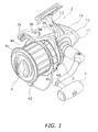
- a spinning reel employing a first exemplary embodiment of the present invention is a spinning reel for surf casting and mainly includes a handle 1, a reel unit 2, a rotor 3 and a spool 4.
- the reel unit 2 is attached to a fishing rod.
- the rotor 3 is rotatably attached to the front portion of the reel unit 2.
- the spool 4 is disposed at the front of the rotor 3 and is configured to move back and forth.
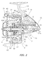
- the spinning reel includes a rotor drive mechanism 5 and an oscillation mechanism 6.
- the rotor drive mechanism 5 is configured to drive and rotate the rotor 3 in conjunction with rotation of the handle 1.
- the oscillation mechanism 6 is configured to move the spool 4 back and forth in conjunction with rotation of the rotor 3.
- the reel unit 2 contains the rotor drive mechanism 5 and the oscillation mechanism 6 in the interior thereof.
- the reel unit 2 includes a chassis 10, a first lid member 11, a second lid member 12, a fishing rod attachment leg 13, a first cover member 14 and a second cover member 15.
- the chassis 10 is laterally open at both sides.
- the first and second lid members 11 and 12 cover the open lateral sides of the chassis 10, respectively.
- the fishing rod attachment leg 13 is integrally formed with the chassis 10.
- the first and second cover members 14 and 15 cover the chassis 10, the first lid member 11 and the second lid member from behind.
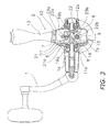
- the rotor drive mechanism 5 includes a master gear shaft 8, a master gear 7 and a pinion gear 9.
- a handle shaft 1a of the handle 1 is screwed and fixed into the master gear shaft 8.
- the master gear 7 is integrally formed with the master gear shaft 8.
- the pinion gear 9 is meshed with the master gear 7.
- the master gear shaft 8 is a solid core member made of aluminum alloy.
- the master gear shaft 8 is integrally molded with the master gear 7.
- the master gear shaft 8 is rotatably attached to the reel unit 2 through a bearing 19a and a bearing 19b.
- the bearing 19a is attached to a first boss 11a formed on the first lid member 11 of the reel unit 2, whereas the bearing 19b is attached to a second boss 11b formed on the second lid member 12 of the reel unit 2.
- the master gear 7 is a face gear made of, for instance, aluminum alloy.
- the master gear 7 is integrally molded with the master gear shaft 8. As illustrated in FIG. 3 , the master gear 7 is disposed such that a gear portion 7a thereof faces to the right.
- the gear portion 7a is formed with helical gear teeth meshing with the pinion gear 9.
- the pinion gear 9 is a hollow tubular member.
- the front portion of the pinion gear 9 penetrates the rotor 3.
- the rotor 3 is thus attached onto the pinion gear 9 in a non-rotatable state.
- a spool shaft 16 is disposed in the inner periphery of the pinion gear 9 while penetrating through the pinion gear 9.
- a nut 17 is attached onto the front portion of the pinion gear 9.
- the rotor 3 is thus fixed to the pinion gear 9 by means of the nut 17.
- the pinion gear 9 is rotatably supported by the chassis 10 of the reel unit 2 through a bearing 18a and a bearing 18b.
- the bearing 18a supports an axially intermediate portion of the pinion gear 9, whereas the bearing 18b supports an axially rear portion of the pinion gear 9.
- the oscillation mechanism 6 is a level winding mechanism of a traverse cam type and includes a deceleration mechanism 20, a traverse cam shaft 21, a slider 22 and two guide shafts 23a and 23b.
- the deceleration mechanism 20 meshes with the pinion gear 9 (see FIG. 2 ).
- the traverse cam shaft 21 is configured to rotate in conjunction with the deceleration mechanism 20.
- the slider 22 is configured to move back and forth while being engaged with the traverse cam shaft 21.
- the guide shafts 23a and 23b are configured to guide the slider 22 along the spool shaft 16.
- the traverse cam shaft 21 includes intersecting helical grooves 21 a on the outer peripheral surface thereof.
- the slider 22 is a member that is coupled to the rear end of the spool shaft 16 in a non-rotatable state.
- the slider 22 includes an engagement member 22a and a slider body 22b.
- the engagement member 22a is engaged with the helical grooves 21a of the traverse cam shaft 21.
- the engagement member 22a is attached to the slider body 22b.
- the slider body 22b is configured to move back and forth in conjunction with rotation of the traverse cam shaft 21.
- the slider 22 is configured to reciprocate along the spool shaft 16 in conjunction with rotation of the traverse cam shaft 21 due to the aforementioned structure in which the tip of the engagement member 22a is engaged with the helical grooves 21a.
- the spool shaft 16 thereby reciprocates in conjunction with rotation of the handle 1.
- the rotor 3 includes a rotor body 35 and a bail arm 34.
- the rotor body 35 is rotatably attached to the reel unit 2 through the pinion gear 9.
- the bail arm 34 is pivotably attached to the rotor body 35.
- the rotor body 35 is made of, for instance, aluminum alloy.
- the rotor body 35 includes a support portion 30, a first rotor arm 31 and a second rotor arm 32.
- the support portion 30 is a tubular portion fixed to the pinion gear 9.
- the first and second rotor arms 31 and 32 respectively extend forwards from positions facing the outer peripheral surface of the rear end of the support portion 30, while respectively keeping a predetermined distance from the outer periphery of the support portion 30.
- the support portion 30, the first rotor arm 31 and the second rotor arm 32, together forming the rotor body 35, are all made of aluminum alloy or the like and are integrally molded by means of die cast molding. As illustrated in FIGS. 1 and 2 , the radially outer periphery of the first rotor arm 31 is covered with a first cover member 36, whereas the radially outer periphery of the second rotor arm 32 is covered with a second cover member 37. Further, a first bail support member 40 is pivotably attached to the outer peripheral side of the tip of the first rotor arm 31, whereas a second bail support member 42 is pivotably attached to the outer peripheral side of the tip of the second rotor arm 32.
- the first and second bail support members 40 and 42 form the bail arm 34.
- the bail arm 34 is provided for smoothly guiding the fishing line from the fishing rod to the spool 4 and winding the fishing line onto the spool 4.
- the bail arm 34 is allowed to pivot between a fishing line guide position and a fishing line release position flipped from the fishing line guide position.
- the anti-reverse mechanism 50 includes a roller type one-way clutch 51 attached to the chassis 10.
- the one-way clutch 51 is configured to switch between a reverse prevention state and a reverse permission state.
- the anti-reverse mechanism 50 further includes a switching operation portion 52 for switching the one-way clutch 51 between the reverse prevention state and the reverse permission state.
- the switching operation portion 52 is pivotably supported by the bottom of the chassis 10.
- the spool 4 is a shallow groove spool.
- the spool 4 is detachably coupled to the distal end of the spool shaft 16 in a non-rotatable state.
- the spool shaft 16 includes an anti-rotation portion 16a and a male threaded portion 16b on the outer peripheral surface of the distal end of the spool shaft 16.
- the anti-rotation portion 16a includes a pair of parallel chamfered portions.
- the spool 4 is detachably fixed to the distal end of the spool shaft 16 by means of a spool knob 54 to be screwed onto the male threaded portion 16b.
- the spool 4 is prevented from rotating about the spool shaft 16 by means of an anti-rotation member 55 fixed to the rear surface of the spool 4 by means of screws.
- the anti-rotation member 55 includes an outer peripheral surface 55a having a regular hexagonal cross-section.
- the outer peripheral surface 55a is engaged with the inner peripheral surface of a closed-end tubular sound producing member 56.
- the sound producing member 56 is attached onto the spool shaft 16 in a non-rotatable state.
- the sound producing member 56 makes contact with a circular spool receiver 57.
- the sound producing member 56 and the spool receiver 57 are engaged with the anti-rotation portion 16a and are thereby non-rotatably attached onto the spool shaft 16.
- the spool receiver 57 is prevented from moving axially rearwards by a step formed between the anti-rotation portion 16a and the outer peripheral surface of the spool shaft 16.
- the sound producing member 56 does not function as a sound producing mechanism due to the structure in which the spool 4 is prevented from rotating about the spool shaft 16.
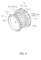
- the spool 4 includes a bobbin trunk 4a, a rear flange 4b, a front flange 4c and a skirt 4d.
- the bobbin trunk 4a is used for winding the fishing line around the outer periphery thereof.
- the rear flange 4b is formed on the rear end of the bobbin trunk 4a.
- the rear flange 4b has a diameter slightly greater than that of the bobbin trunk 4a.
- the front flange 4c is formed on the front end of the bobbin trunk 4a.
- the front flange 4c has a diameter slightly greater than that of the bobbin trunk 4a.
- the skirt 4d is a tubular portion integrally formed with the outer periphery of the rear flange 4b.
- these portions 4a, 4b, 4c and 4d are respectively made of synthetic resin (e.g., short-glass-fiber reinforced polyamide resin) and are formed by means of injection molding.
- the bobbin trunk 4a is disposed on the outer peripheral side of the support portion 30 of the rotor 3.
- the bobbin trunk 4a includes a plurality of coupling ribs 25 (example of a plurality of coupling portions) and a tubular coupling portion 26.
- the coupling ribs 25 are disposed at predetermined intervals along the circumferential direction of the bobbin trunk 4a.
- the tubular coupling portion 26 is disposed between the front flange 4c and the rear flange 4b for connecting the inner peripheries of the coupling ribs 25.
- the bobbin trunk 4a includes a front wall 27 and a boss 28.
- the front wall 27 is a disc-shaped portion formed on the inner peripheral side of the front flange 4c.
- the boss 28, including a through hole 28a, is formed on the radial center portion of the front wall 27.
- the front wall 27 includes a plurality of (e.g., four) ribs 27a on the rear surface thereof for a reinforcement purpose. Specifically, the ribs 27a protrude from the rear surface of the front wall 27 while radially extend from the outer periphery of the boss 28.
- the outer peripheral surface of the spool shaft 16 is rotatably fitted with the through hole 28a of the boss 28. Further, the anti-rotation member 55 is fixed to the rear surface of the boss 28.
- the coupling ribs 25 are each formed along the back-and-forth direction for coupling the front flange 4c and the rear flange 4b.
- the plural coupling ribs 25 are provided for limiting variation in thickness of the bobbin trunk 4a with respect to the thicknesses of the front and rear flanges 4c and 4b.
- the outer peripheral surfaces of the coupling ribs 25 are formed with circular-arc surfaces extending along the back-and-forth direction with the same radius about the spool shaft 16. For example, the number of the coupling ribs 25 is 16 in the first exemplary embodiment.
- the inner peripheral surface of the tubular coupling portion 26 is tapered such that the tubular coupling portion 26 can be easily removed from a die in molding. Specifically, the inner peripheral surface of the tubular coupling portion 26 is tapered at an angle of roughly 0.5 to 2 degrees with respect to the spool shaft 16.
- the tubular coupling portion 26 has an inner diameter increasing from its front side to its back side.
- the rear flange 4b has a diameter slightly greater than that of the front flange 4c.
- the rear flange 4b is an annular portion roughly perpendicular to the bobbin trunk 4a.
- the front flange 4c has a tapered surface slanted forward on the bobbin trunk 4a side.
- the front flange 4c includes a first recessed portion 4g annularly recessed on the front surface thereof for regulating the thickness of the front flange 4c.
- the first recessed portion 4g is continuously formed on the front surface of the front flange 4c along the circumferential direction in this embodiment. However, the first recessed portion 4g may be non-continuously formed at predetermined intervals on the front surface of the front flange 4c along the circumferential direction.
- the skirt 4d is provided with a fishing line holder 4e for holding the fishing line.
- the fishing line holder 4e is disposed in a U-shaped recess.
- the skirt 4d includes a plurality of (e.g., 15) second recessed portions 4f on the outer peripheral surface thereof.
- the second recessed portions 4f are circumferentially disposed at predetermined intervals on the outer periphery of the skirt 4d, excluding a region in which the fishing line holder 4e is attached.
- the second recessed portions 4f are recessed in a rectangular shape, and serve to reduce the weight of the skirt 4d and regulate the thickness of the skirt 4d.
- Annularly aligned portions 4h are formed in the region of the skirt outer periphery including the second recessed portions 4f.
- the spool 4 with the aforementioned structure, it is possible to regulate the thicknesses of the bobbin trunk 4a to vary less with respect to the thicknesses of the front and rear flanges 4b and 4c by means of the plural coupling ribs 25. Accordingly, production of sink marks on the outer periphery of the spool 4 is prevented.
- the coupling ribs 25 of the bobbin trunk 4a of the spool 4 are each disposed along the back-and-forth direction.
- coupling ribs 125 of a bobbin trunk 104a of a spool 104 are obliquely formed while intersecting the back-and-forth direction as illustrated in FIG.6 .
- its coupled portion to the front flange 4c and its coupled portion to the rear flange 4d are circumferentially displaced about the spool shaft 16 at an angle of, for instance, 22.5 degrees.
- a tubular coupling portion 126 connects the inner peripheries of the coupling ribs 125.
- the other spool elements of the second exemplary embodiment are the same as those of the first exemplary embodiment. Therefore, explanation thereof will be omitted.
- a bobbin trunk 204a of a spool 204 of a third exemplary embodiment further includes a single or plurality of annular portions 229.
- the annular portion/portions 229 is/are disposed perpendicular to the spool shaft 16 for circumferentially connecting a plurality of coupling ribs 225.
- three annular portions 229 are disposed at predetermined intervals along the back-and-forth direction.
- a tubular coupling portion 226 connects the inner peripheries of the coupling ribs 225.
- the other spool elements of the third exemplary embodiment are the same as those of the first exemplary embodiment. Therefore, explanation thereof will be omitted.
- a bobbin trunk 304a of a spool 304 of a fourth exemplary embodiment includes a plurality of coupling ribs 325 and a tubular coupling portion 326.
- the coupling ribs 325 are formed with a plurality of first coupling ribs 325a and a plurality of second coupling ribs 325b.
- the first coupling ribs 325a are obliquely disposed along a first direction that intersects the back-and-forth direction.
- the second coupling ribs 325b are obliquely disposed along a second direction that intersects the first direction.
- the first coupling ribs 325a and the second coupling ribs 325b are obliquely disposed in opposite directions. In other words, the first coupling ribs 325a and the second coupling ribs 325b intersect at axial positions between the front flange 4c and the rear flange 4d.
- the coupling ribs 325 are reinforced due to intersections 325c, and circumferential stiffness thereof is thereby enhanced.
- the tubular coupling portion 326 connects the inner peripheries of the coupling ribs 325.
- the other spool elements of the fourth exemplary embodiment are the same as those of the first exemplary embodiment. Therefore, explanation thereof will be omitted.
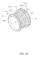
- a bobbin trunk 404a of a spool 404 of a fifth exemplary embodiment is similar to but different from the spool 4 of the first exemplary embodiment in that the bobbin trunk 404a does not include the tubular coupling portion 26 of the spool 4. Therefore, coupling ribs 425 extend radially inwards from the outer periphery of the bobbin trunk 404a to positions where the inner peripheral surface of the coupling tubular portion 26 is disposed in the first exemplary embodiment.
- recessed portions 404f are formed in a skirt 404d while penetrating the inner and outer peripheral surfaces of the skirt 404d. Weight reduction is further achieved in the spool 404 with the formation of the recessed portions 404f that penetrate the inner and outer peripheral surfaces of the skirt 404d.
- the other spool elements of the fifth exemplary embodiment are the same as those of the first exemplary embodiment. Therefore, explanation thereof will be omitted.
- a bobbin trunk 504a of a spool 504 of a sixth aspect of the present invention is similar to but different from the bobbin trunk 204a with the annular portions 229 of the third exemplary embodiment in that the bobbin trunk 504a does not include the tubular coupling portion 226 of the bobbin trunk 204a.
- coupling ribs 525 and annular portions 529 extend radially inwards from the outer periphery of the bobbin trunk 504a to positions where the inner peripheral surface of the tubular coupling portion 226 is disposed in the third exemplary embodiment.
- recessed portions 504f penetrate the inner and outer peripheral surfaces of a skirt 504d.
- the other spool elements are the same as those of the first exemplary embodiment. Therefore, explanation thereof will be omitted.
- a bobbin trunk 604a of a spool 604 of a seventh exemplary embodiment is similar to but different from the bobbin trunk 304a of the fourth exemplary embodiment including the coupling ribs 325 formed by the first coupling ribs 325a and the second coupling ribs 325b in that the bobbin trunk 604a does not include the tubular coupling portion 326 of the bobbin trunk 304a.
- coupling ribs 625 extend radially inwards from the outer periphery of the bobbin trunk 604a to positions where the inner peripheral surface of the tubular coupling portion 326 is disposed in the fourth exemplary embodiment.
- the other spool elements of the seventh exemplary embodiment, including the recessed portions 4f, are the same as those of the first exemplary embodiment. Therefore, explanation thereof will be omitted.
- a bobbin trunk 704a of a spool 704 of an eighth exemplary embodiment is similar to but different from the bobbin trunk 604a of the seventh exemplary embodiment including the coupling ribs 625 formed by the first coupling ribs 625a and the second coupling ribs 625b in that the bobbin trunk 704a includes an annular portion 729.
- the annular portion 729 and coupling ribs 725 formed by first coupling ribs 725a and second coupling ribs 725b extend radially inwards to the same positions as those of the coupling ribs 625.
- the other spool elements of the eighth exemplary embodiment, including the recessed portions4f, are the same as those of the first exemplary embodiment. Therefore, explanation thereof will be omitted.
- the spinning reel spool 4 (104, 204...704) is attached onto the spool shaft 16 mounted movably back and forth in the reel unit 2 for winding the fishing line thereon.
- the spool 4 (104, 204...704) includes the front flange 4c, the rear flange 4b and the bobbin trunk 4a (104a, 204a...704a).
- the rear flange 4b is disposed rearwards of the front flange 4c.
- the bobbin trunk 4a (104a, 204a...704a) includes a plurality of the coupling ribs 25 (125, 225...725) circumferentially disposed at predetermined intervals for coupling the front and rear flanges 4b and 4c.
- the bobbin trunk 4a is integrally formed with the front and rear flanges 4b and 4c. The diameter of the bobbin trunk 4a is less than the diameters of the front and rear flanges 4b and 4b.
- the bobbin trunk 4a (104a, 204a...704a) includes the plural coupling ribs 25 (125, 225...725).
- the coupling ribs 25 (125, 225...725) couples the front flange 4c and the rear flange 4b. It is possible to regulate the thicknesses of the bobbin trunk 4a (104a, 204a...704a) to vary less with respect to the thicknesses of the front and rear flanges 4b and 4c by means of the plural coupling ribs 25 (125, 225...725).
- the bobbin trunk 4a (104a, 204a, 304a) further includes the tubular coupling portion 26 (126, 226, 326) that connects the inner peripheries of the plural coupling ribs 25 (125, 225, 325).
- circumferential stiffness of the bobbin trunk 4a (104a, 204a, 304a) is enhanced due to the structure in which the inner peripheries of the coupling ribs 25 (125, 225, 325) are connected by the tubular coupling portion 26 (126, 226, 326).
- the plural coupling ribs 25 are each disposed along the back-and-forth direction.
- the coupling ribs 25 have a simple structure. Accordingly, the spool 4 (204, 404, 504), including the coupling ribs 25 (225, 425, 525), can be easily manufactured by injection molding.
- the plural coupling ribs 32 5 are formed with the first coupling ribs 325a and the second coupling ribs 325b.
- the first coupling ribs 325a are obliquely disposed along the first direction that intersects the back-and-forth direction
- the second coupling ribs 325b are obliquely disposed along the second direction that intersects the first direction.
- the coupling ribs 32 5 are formed with the first coupling ribs 325a and the second coupling ribs 325b, which obliquely intersect with each other along the first and second directions.
- the bobbin trunk 204a (504a, 704a) further includes a single or plurality of the annular portions 229 (529, 729) disposed perpendicular to the spool shaft 16 for circumferentially connecting the coupling ribs 225 (525, 625).
- circumferential stiffness is further enhanced in the bobbin trunk 204a (504a, 704a) due to the structure in which the coupling ribs 225 (525, 625), circumferentially disposed at predetermined intervals, are circumferentially connected by the annular portion 229 (529, 729).
- the spool 4 (104, 204...704) further includes the tubular skirt 4d (404d) integrally formed with the outer periphery of the rear flange 4b.
- stiffness of the spool 4 (104, 204...704) can be enhanced as a whole by the tubular skirt 4d (404d).
- the coupling ribs are each linearly formed along the back-and-forth direction or the directions intersecting the back-and-forth direction.
- the directions and shapes of the coupling ribs may not be particularly limited as long as the coupling ribs couple the front flange and the rear flange.
- the front flange and the rear flange may be coupled by either a plurality of linearly bending lines or a plurality of winding curves (e.g., spiral curves).
- the spool surface is not particularly processed.
- a hard coating may be formed on fishing-line contactable portions (i.e., the bobbin trunk, the front flange, the rear flange of the spool and the like) by means of hard plating, ion plating or the like.
Claims (6)
- Tambour de moulinet de pêche à lancer (4, 104, 204, 304) attaché sur un arbre de tambour (16) et monté mobile pour se déplacer dans un mouvement de va-et-vient dans une unité de moulinet pour l'enroulement d'une ligne de pêche sur celui-ci, comprenant :un rebord avant (4c) ;un rebord arrière (4b) disposé à l'arrière du rebord avant ; et un tronc de bobine (4a) formé intégralement avec le rebord avant et le rebord arrière, le tronc de bobine (4a) ayant un diamètre inférieur aux diamètres des rebords ou flasques avant et arrière, le tronc de bobine (4a) comprenant une pluralité de parties de couplage (25) pour coupler le rebord avant et le rebord arrière, des parties de couplage étant disposées à des intervalles prédéterminés dans une direction circonférentielle du tronc de bobine, caractérisé en ce que le tronc de bobine (4) comprend en outre une partie de couplage tubulaire (26) entre le rebord avant et le rebord arrière pour connecter des périphéries internes des parties de couplage, la partie de couplage tubulaire ayant un diamètre interne allant en augmentant en partant de son extrémité avant, la surface périphérique interne de la partie de couplage tubulaire étant incliné ou biseautée à un angle d'environ 05 à 2 degrés par rapport à l'arbre de tambour.
- Tambour de moulinet de pêche à lancer selon la revendication 1, dans lequel les parties de couplage (25, 225) sont disposées chacune dans une direction avant - arrière ou de va et vient.
- Tambour de moulinet de pêche à lancer selon la revendication 1, dans lequel les parties de couplage (125, 325) sont disposées à l'oblique pour croiser une direction avant - arrière ou de va et vient.
- Tambour de moulinet de pêche à lancer selon la revendication 3, dans lequel les parties de couplage (325) comprennent une pluralité de premières parties de couplage (325a) et une pluralité de deuxièmes parties de couplage (325b), les premières parties de couplage étant disposées à l'oblique le long d'une première direction croisant la direction avant - arrière ou de va et vient, les deuxièmes parties de couplage étant disposées à l'oblique le long d'une deuxième direction croisant la première direction.
- Tambour de moulinet de pêche à lancer selon l'une quelconque des revendications 1 à 4, dans lequel le tronc de bobine comprend en outre au moins une partie annulaire disposée perpendiculairement à l'arbre de tambour pour connecter les parties de couplage dans la direction circonférentielle du tronc de bobine.
- Tambour de moulinet de pêche à lancer selon l'une quelconque des revendications 1 à 5, comprenant en outre une jupe tubulaire formée intégralement avec la partie périphérique externe du rebord arrière.
Applications Claiming Priority (1)
| Application Number | Priority Date | Filing Date | Title |
|---|---|---|---|
| JP2010114385A JP5680335B2 (ja) | 2010-05-18 | 2010-05-18 | スピニングリールのスプール |
Publications (2)
| Publication Number | Publication Date |
|---|---|
| EP2387881A1 EP2387881A1 (fr) | 2011-11-23 |
| EP2387881B1 true EP2387881B1 (fr) | 2015-07-29 |
Family
ID=44475092
Family Applications (1)
| Application Number | Title | Priority Date | Filing Date |
|---|---|---|---|
| EP11159490.9A Active EP2387881B1 (fr) | 2010-05-18 | 2011-03-24 | Bobine de moulinet de pêche |
Country Status (5)
| Country | Link |
|---|---|
| EP (1) | EP2387881B1 (fr) |
| JP (1) | JP5680335B2 (fr) |
| KR (1) | KR101740930B1 (fr) |
| CN (1) | CN102246730B (fr) |
| TW (1) | TWI566695B (fr) |
Families Citing this family (3)
| Publication number | Priority date | Publication date | Assignee | Title |
|---|---|---|---|---|
| JP5779516B2 (ja) * | 2012-02-06 | 2015-09-16 | グローブライド株式会社 | 釣糸巻回用スプールと、このスプールを搭載した魚釣用リール |
| JP6462382B2 (ja) * | 2015-01-29 | 2019-01-30 | 株式会社シマノ | 係合ピン及び係合ピンを有する釣り用リールの往復移動機構 |
| CN112262828A (zh) * | 2020-11-19 | 2021-01-26 | 许一帆 | 一种可实现缓冲的定位卡线装置 |
Family Cites Families (18)
| Publication number | Priority date | Publication date | Assignee | Title |
|---|---|---|---|---|
| JPS4970088U (fr) * | 1972-10-03 | 1974-06-18 | ||
| JPH0445506Y2 (fr) * | 1985-07-22 | 1992-10-26 | ||
| JPH0452470U (fr) * | 1990-09-07 | 1992-05-01 | ||
| JP3137902B2 (ja) | 1996-05-31 | 2001-02-26 | 株式会社熊谷組 | 地中連続壁構築用の掘削装置 |
| JP3033414U (ja) * | 1996-07-10 | 1997-01-28 | ダイワ精工株式会社 | 魚釣用スピニングリ−ル |
| JP3443811B2 (ja) * | 1997-01-28 | 2003-09-08 | ダイワ精工株式会社 | 魚釣用スピニングリール |
| JPH1146635A (ja) * | 1997-08-08 | 1999-02-23 | Shimano Inc | 釣り用リールのスプール |
| JP3512683B2 (ja) * | 1999-08-04 | 2004-03-31 | ダイワ精工株式会社 | 魚釣用リール |
| JP2001148973A (ja) * | 1999-11-26 | 2001-06-05 | Shimano Inc | スピニングリールのスプール |
| JP2004081097A (ja) * | 2002-08-27 | 2004-03-18 | Shimano Inc | スピニングリールの発音機構 |
| JP3981325B2 (ja) * | 2002-12-06 | 2007-09-26 | 株式会社シマノ | スピニングリールのスプール支持構造 |
| JP3958737B2 (ja) | 2003-12-03 | 2007-08-15 | 弘孝 寺田 | 魚釣り用リールのスプール |
| JP4476790B2 (ja) * | 2004-11-25 | 2010-06-09 | グローブライド株式会社 | 魚釣用スピニングリ−ル |
| JP4795135B2 (ja) * | 2006-06-27 | 2011-10-19 | グローブライド株式会社 | 魚釣用スピニングリールのスプール |
| JP3137902U (ja) * | 2007-09-28 | 2007-12-13 | 世淵 葉 | 魚釣り用リール |
| JP5205121B2 (ja) * | 2008-04-30 | 2013-06-05 | 株式会社シマノ | スピニングリールのスプール |
| KR20100040393A (ko) * | 2008-10-10 | 2010-04-20 | 강석운 | 드래그 유닛 장착 호환성을 갖는 플라이 리일 |
| CN201388450Y (zh) * | 2009-02-23 | 2010-01-27 | 威海光威精密机械有限公司 | 渔线轮的卷线轮 |
-
2010
- 2010-05-18 JP JP2010114385A patent/JP5680335B2/ja active Active
-
2011
- 2011-03-24 EP EP11159490.9A patent/EP2387881B1/fr active Active
- 2011-03-25 TW TW100110413A patent/TWI566695B/zh active
- 2011-04-19 KR KR1020110036314A patent/KR101740930B1/ko active IP Right Grant
- 2011-04-22 CN CN201110104003.6A patent/CN102246730B/zh not_active Expired - Fee Related
Also Published As
| Publication number | Publication date |
|---|---|
| CN102246730A (zh) | 2011-11-23 |
| EP2387881A1 (fr) | 2011-11-23 |
| TW201200013A (en) | 2012-01-01 |
| CN102246730B (zh) | 2014-11-26 |
| JP5680335B2 (ja) | 2015-03-04 |
| TWI566695B (zh) | 2017-01-21 |
| KR20110127065A (ko) | 2011-11-24 |
| JP2011239722A (ja) | 2011-12-01 |
| KR101740930B1 (ko) | 2017-06-15 |
Similar Documents
| Publication | Publication Date | Title |
|---|---|---|
| KR101676855B1 (ko) | 낚시용 릴의 트래버스 캠축 및 그것을 이용한 낚시용 릴의 왕복 이동 기구 | |
| EP2842420B1 (fr) | Moulinet de pêche | |
| US8011610B2 (en) | Fishing reel handle assembly | |
| US9004386B2 (en) | Spinning reel fishing line guide mechanism and spinning reel | |
| JP2007189982A (ja) | 釣り用リールのギア部品装着構造 | |
| EP2347649B1 (fr) | Structure de support de bobine pour moulinet de pêche | |
| US6883738B2 (en) | Spinning reel handle assembly | |
| US9210923B2 (en) | Spinning reel | |
| JP2009261367A (ja) | 釣り用リールのハンドル把手 | |
| EP2387881B1 (fr) | Bobine de moulinet de pêche | |
| JP2016165255A (ja) | 釣り用リールの往復移動機構及び釣り用リール | |
| JP2009261367A5 (fr) | ||
| TW200302696A (en) | Reel unit for spinning reel | |
| US7967232B2 (en) | Spinning-reel fishing line guide mechanism | |
| US9149029B2 (en) | Spinning reel | |
| US8939391B2 (en) | Spinning reel body and spinning reel | |
| JP5869240B2 (ja) | 釣り用リールのハンドル把手 | |
| EP1332670A1 (fr) | Transmission de puissance pour moulinet de pêche | |
| JP5010860B2 (ja) | 釣り用リールのハンドル把手 | |
| US10028494B2 (en) | Spinning reel rotor and spinning reel | |
| EP1386537A1 (fr) | Moulinet de pêche | |
| JP4827242B2 (ja) | 魚釣用スピニングリール | |
| JP2009065935A (ja) | スピニングリールのロータ及びロータ本体 | |
| JP2010035427A (ja) | スピニングリールのリール本体 | |
| JP2011092046A (ja) | スピニングリールの釣り糸案内機構 |
Legal Events
| Date | Code | Title | Description |
|---|---|---|---|
| AK | Designated contracting states |
Kind code of ref document: A1 Designated state(s): AL AT BE BG CH CY CZ DE DK EE ES FI FR GB GR HR HU IE IS IT LI LT LU LV MC MK MT NL NO PL PT RO RS SE SI SK SM TR |
|
| AX | Request for extension of the european patent |
Extension state: BA ME |
|
| PUAI | Public reference made under article 153(3) epc to a published international application that has entered the european phase |
Free format text: ORIGINAL CODE: 0009012 |
|
| 17P | Request for examination filed |
Effective date: 20120328 |
|
| 17Q | First examination report despatched |
Effective date: 20130827 |
|
| GRAP | Despatch of communication of intention to grant a patent |
Free format text: ORIGINAL CODE: EPIDOSNIGR1 |
|
| INTG | Intention to grant announced |
Effective date: 20150217 |
|
| GRAS | Grant fee paid |
Free format text: ORIGINAL CODE: EPIDOSNIGR3 |
|
| GRAA | (expected) grant |
Free format text: ORIGINAL CODE: 0009210 |
|
| AK | Designated contracting states |
Kind code of ref document: B1 Designated state(s): AL AT BE BG CH CY CZ DE DK EE ES FI FR GB GR HR HU IE IS IT LI LT LU LV MC MK MT NL NO PL PT RO RS SE SI SK SM TR |
|
| REG | Reference to a national code |
Ref country code: GB Ref legal event code: FG4D |
|
| REG | Reference to a national code |
Ref country code: CH Ref legal event code: EP |
|
| REG | Reference to a national code |
Ref country code: AT Ref legal event code: REF Ref document number: 738528 Country of ref document: AT Kind code of ref document: T Effective date: 20150815 |
|
| REG | Reference to a national code |
Ref country code: IE Ref legal event code: FG4D |
|
| REG | Reference to a national code |
Ref country code: DE Ref legal event code: R096 Ref document number: 602011018154 Country of ref document: DE |
|
| REG | Reference to a national code |
Ref country code: AT Ref legal event code: MK05 Ref document number: 738528 Country of ref document: AT Kind code of ref document: T Effective date: 20150729 |
|
| REG | Reference to a national code |
Ref country code: LT Ref legal event code: MG4D |
|
| REG | Reference to a national code |
Ref country code: NL Ref legal event code: MP Effective date: 20150729 |
|
| PG25 | Lapsed in a contracting state [announced via postgrant information from national office to epo] |
Ref country code: NO Free format text: LAPSE BECAUSE OF FAILURE TO SUBMIT A TRANSLATION OF THE DESCRIPTION OR TO PAY THE FEE WITHIN THE PRESCRIBED TIME-LIMIT Effective date: 20151029 Ref country code: FI Free format text: LAPSE BECAUSE OF FAILURE TO SUBMIT A TRANSLATION OF THE DESCRIPTION OR TO PAY THE FEE WITHIN THE PRESCRIBED TIME-LIMIT Effective date: 20150729 Ref country code: LV Free format text: LAPSE BECAUSE OF FAILURE TO SUBMIT A TRANSLATION OF THE DESCRIPTION OR TO PAY THE FEE WITHIN THE PRESCRIBED TIME-LIMIT Effective date: 20150729 Ref country code: GR Free format text: LAPSE BECAUSE OF FAILURE TO SUBMIT A TRANSLATION OF THE DESCRIPTION OR TO PAY THE FEE WITHIN THE PRESCRIBED TIME-LIMIT Effective date: 20151030 Ref country code: LT Free format text: LAPSE BECAUSE OF FAILURE TO SUBMIT A TRANSLATION OF THE DESCRIPTION OR TO PAY THE FEE WITHIN THE PRESCRIBED TIME-LIMIT Effective date: 20150729 |
|
| PG25 | Lapsed in a contracting state [announced via postgrant information from national office to epo] |
Ref country code: PL Free format text: LAPSE BECAUSE OF FAILURE TO SUBMIT A TRANSLATION OF THE DESCRIPTION OR TO PAY THE FEE WITHIN THE PRESCRIBED TIME-LIMIT Effective date: 20150729 Ref country code: PT Free format text: LAPSE BECAUSE OF FAILURE TO SUBMIT A TRANSLATION OF THE DESCRIPTION OR TO PAY THE FEE WITHIN THE PRESCRIBED TIME-LIMIT Effective date: 20151130 Ref country code: SE Free format text: LAPSE BECAUSE OF FAILURE TO SUBMIT A TRANSLATION OF THE DESCRIPTION OR TO PAY THE FEE WITHIN THE PRESCRIBED TIME-LIMIT Effective date: 20150729 Ref country code: ES Free format text: LAPSE BECAUSE OF FAILURE TO SUBMIT A TRANSLATION OF THE DESCRIPTION OR TO PAY THE FEE WITHIN THE PRESCRIBED TIME-LIMIT Effective date: 20150729 Ref country code: RS Free format text: LAPSE BECAUSE OF FAILURE TO SUBMIT A TRANSLATION OF THE DESCRIPTION OR TO PAY THE FEE WITHIN THE PRESCRIBED TIME-LIMIT Effective date: 20150729 Ref country code: AT Free format text: LAPSE BECAUSE OF FAILURE TO SUBMIT A TRANSLATION OF THE DESCRIPTION OR TO PAY THE FEE WITHIN THE PRESCRIBED TIME-LIMIT Effective date: 20150729 Ref country code: HR Free format text: LAPSE BECAUSE OF FAILURE TO SUBMIT A TRANSLATION OF THE DESCRIPTION OR TO PAY THE FEE WITHIN THE PRESCRIBED TIME-LIMIT Effective date: 20150729 Ref country code: IS Free format text: LAPSE BECAUSE OF FAILURE TO SUBMIT A TRANSLATION OF THE DESCRIPTION OR TO PAY THE FEE WITHIN THE PRESCRIBED TIME-LIMIT Effective date: 20151129 |
|
| REG | Reference to a national code |
Ref country code: FR Ref legal event code: PLFP Year of fee payment: 6 |
|
| PG25 | Lapsed in a contracting state [announced via postgrant information from national office to epo] |
Ref country code: NL Free format text: LAPSE BECAUSE OF FAILURE TO SUBMIT A TRANSLATION OF THE DESCRIPTION OR TO PAY THE FEE WITHIN THE PRESCRIBED TIME-LIMIT Effective date: 20150729 |
|
| PG25 | Lapsed in a contracting state [announced via postgrant information from national office to epo] |
Ref country code: IT Free format text: LAPSE BECAUSE OF FAILURE TO SUBMIT A TRANSLATION OF THE DESCRIPTION OR TO PAY THE FEE WITHIN THE PRESCRIBED TIME-LIMIT Effective date: 20150729 Ref country code: SK Free format text: LAPSE BECAUSE OF FAILURE TO SUBMIT A TRANSLATION OF THE DESCRIPTION OR TO PAY THE FEE WITHIN THE PRESCRIBED TIME-LIMIT Effective date: 20150729 Ref country code: DK Free format text: LAPSE BECAUSE OF FAILURE TO SUBMIT A TRANSLATION OF THE DESCRIPTION OR TO PAY THE FEE WITHIN THE PRESCRIBED TIME-LIMIT Effective date: 20150729 Ref country code: CZ Free format text: LAPSE BECAUSE OF FAILURE TO SUBMIT A TRANSLATION OF THE DESCRIPTION OR TO PAY THE FEE WITHIN THE PRESCRIBED TIME-LIMIT Effective date: 20150729 Ref country code: EE Free format text: LAPSE BECAUSE OF FAILURE TO SUBMIT A TRANSLATION OF THE DESCRIPTION OR TO PAY THE FEE WITHIN THE PRESCRIBED TIME-LIMIT Effective date: 20150729 |
|
| REG | Reference to a national code |
Ref country code: DE Ref legal event code: R097 Ref document number: 602011018154 Country of ref document: DE |
|
| PG25 | Lapsed in a contracting state [announced via postgrant information from national office to epo] |
Ref country code: RO Free format text: LAPSE BECAUSE OF FAILURE TO SUBMIT A TRANSLATION OF THE DESCRIPTION OR TO PAY THE FEE WITHIN THE PRESCRIBED TIME-LIMIT Effective date: 20150729 |
|
| PLBE | No opposition filed within time limit |
Free format text: ORIGINAL CODE: 0009261 |
|
| STAA | Information on the status of an ep patent application or granted ep patent |
Free format text: STATUS: NO OPPOSITION FILED WITHIN TIME LIMIT |
|
| 26N | No opposition filed |
Effective date: 20160502 |
|
| PG25 | Lapsed in a contracting state [announced via postgrant information from national office to epo] |
Ref country code: BE Free format text: LAPSE BECAUSE OF NON-PAYMENT OF DUE FEES Effective date: 20160331 Ref country code: SI Free format text: LAPSE BECAUSE OF FAILURE TO SUBMIT A TRANSLATION OF THE DESCRIPTION OR TO PAY THE FEE WITHIN THE PRESCRIBED TIME-LIMIT Effective date: 20150729 |
|
| PG25 | Lapsed in a contracting state [announced via postgrant information from national office to epo] |
Ref country code: MC Free format text: LAPSE BECAUSE OF FAILURE TO SUBMIT A TRANSLATION OF THE DESCRIPTION OR TO PAY THE FEE WITHIN THE PRESCRIBED TIME-LIMIT Effective date: 20150729 |
|
| REG | Reference to a national code |
Ref country code: CH Ref legal event code: PL |
|
| REG | Reference to a national code |
Ref country code: IE Ref legal event code: MM4A |
|
| PG25 | Lapsed in a contracting state [announced via postgrant information from national office to epo] |
Ref country code: BE Free format text: LAPSE BECAUSE OF FAILURE TO SUBMIT A TRANSLATION OF THE DESCRIPTION OR TO PAY THE FEE WITHIN THE PRESCRIBED TIME-LIMIT Effective date: 20150729 |
|
| PG25 | Lapsed in a contracting state [announced via postgrant information from national office to epo] |
Ref country code: CH Free format text: LAPSE BECAUSE OF NON-PAYMENT OF DUE FEES Effective date: 20160331 Ref country code: LI Free format text: LAPSE BECAUSE OF NON-PAYMENT OF DUE FEES Effective date: 20160331 Ref country code: IE Free format text: LAPSE BECAUSE OF NON-PAYMENT OF DUE FEES Effective date: 20160324 |
|
| REG | Reference to a national code |
Ref country code: FR Ref legal event code: PLFP Year of fee payment: 7 |
|
| PGFP | Annual fee paid to national office [announced via postgrant information from national office to epo] |
Ref country code: LU Payment date: 20170308 Year of fee payment: 7 |
|
| PG25 | Lapsed in a contracting state [announced via postgrant information from national office to epo] |
Ref country code: MT Free format text: LAPSE BECAUSE OF FAILURE TO SUBMIT A TRANSLATION OF THE DESCRIPTION OR TO PAY THE FEE WITHIN THE PRESCRIBED TIME-LIMIT Effective date: 20150729 |
|
| REG | Reference to a national code |
Ref country code: FR Ref legal event code: PLFP Year of fee payment: 8 |
|
| PG25 | Lapsed in a contracting state [announced via postgrant information from national office to epo] |
Ref country code: SM Free format text: LAPSE BECAUSE OF FAILURE TO SUBMIT A TRANSLATION OF THE DESCRIPTION OR TO PAY THE FEE WITHIN THE PRESCRIBED TIME-LIMIT Effective date: 20150729 Ref country code: CY Free format text: LAPSE BECAUSE OF FAILURE TO SUBMIT A TRANSLATION OF THE DESCRIPTION OR TO PAY THE FEE WITHIN THE PRESCRIBED TIME-LIMIT Effective date: 20150729 Ref country code: HU Free format text: LAPSE BECAUSE OF FAILURE TO SUBMIT A TRANSLATION OF THE DESCRIPTION OR TO PAY THE FEE WITHIN THE PRESCRIBED TIME-LIMIT; INVALID AB INITIO Effective date: 20110324 |
|
| PG25 | Lapsed in a contracting state [announced via postgrant information from national office to epo] |
Ref country code: TR Free format text: LAPSE BECAUSE OF FAILURE TO SUBMIT A TRANSLATION OF THE DESCRIPTION OR TO PAY THE FEE WITHIN THE PRESCRIBED TIME-LIMIT Effective date: 20150729 Ref country code: MT Free format text: LAPSE BECAUSE OF FAILURE TO SUBMIT A TRANSLATION OF THE DESCRIPTION OR TO PAY THE FEE WITHIN THE PRESCRIBED TIME-LIMIT Effective date: 20160331 Ref country code: MK Free format text: LAPSE BECAUSE OF FAILURE TO SUBMIT A TRANSLATION OF THE DESCRIPTION OR TO PAY THE FEE WITHIN THE PRESCRIBED TIME-LIMIT Effective date: 20150729 |
|
| PG25 | Lapsed in a contracting state [announced via postgrant information from national office to epo] |
Ref country code: BG Free format text: LAPSE BECAUSE OF FAILURE TO SUBMIT A TRANSLATION OF THE DESCRIPTION OR TO PAY THE FEE WITHIN THE PRESCRIBED TIME-LIMIT Effective date: 20150729 |
|
| PG25 | Lapsed in a contracting state [announced via postgrant information from national office to epo] |
Ref country code: AL Free format text: LAPSE BECAUSE OF FAILURE TO SUBMIT A TRANSLATION OF THE DESCRIPTION OR TO PAY THE FEE WITHIN THE PRESCRIBED TIME-LIMIT Effective date: 20150729 |
|
| PG25 | Lapsed in a contracting state [announced via postgrant information from national office to epo] |
Ref country code: LU Free format text: LAPSE BECAUSE OF NON-PAYMENT OF DUE FEES Effective date: 20180324 |
|
| PGFP | Annual fee paid to national office [announced via postgrant information from national office to epo] |
Ref country code: FR Payment date: 20210210 Year of fee payment: 11 |
|
| PGFP | Annual fee paid to national office [announced via postgrant information from national office to epo] |
Ref country code: GB Payment date: 20210318 Year of fee payment: 11 |
|
| GBPC | Gb: european patent ceased through non-payment of renewal fee |
Effective date: 20220324 |
|
| PG25 | Lapsed in a contracting state [announced via postgrant information from national office to epo] |
Ref country code: GB Free format text: LAPSE BECAUSE OF NON-PAYMENT OF DUE FEES Effective date: 20220324 Ref country code: FR Free format text: LAPSE BECAUSE OF NON-PAYMENT OF DUE FEES Effective date: 20220331 |
|
| REG | Reference to a national code |
Ref country code: DE Ref legal event code: R082 Ref document number: 602011018154 Country of ref document: DE Representative=s name: SONNENBERG HARRISON PARTNERSCHAFT MBB PATENT- , DE |
|
| REG | Reference to a national code |
Ref country code: DE Ref legal event code: R081 Ref document number: 602011018154 Country of ref document: DE Owner name: SHIMANO INC., SAKAI-SHI, JP Free format text: FORMER OWNER: SHIMANO COMPONENTS (MALAYSIA) SDN BHD, PONTIAN, JOHOR, MY |
|
| P01 | Opt-out of the competence of the unified patent court (upc) registered |
Effective date: 20230426 |
|
| PGFP | Annual fee paid to national office [announced via postgrant information from national office to epo] |
Ref country code: DE Payment date: 20240130 Year of fee payment: 14 |