EP2379794B1 - Haushalts-geschirrspülmaschine - Google Patents
Haushalts-geschirrspülmaschine Download PDFInfo
- Publication number
- EP2379794B1 EP2379794B1 EP09764491.8A EP09764491A EP2379794B1 EP 2379794 B1 EP2379794 B1 EP 2379794B1 EP 09764491 A EP09764491 A EP 09764491A EP 2379794 B1 EP2379794 B1 EP 2379794B1
- Authority
- EP
- European Patent Office
- Prior art keywords
- handle
- shell cover
- domestic dishwasher
- shell
- operating panel
- Prior art date
- Legal status (The legal status is an assumption and is not a legal conclusion. Google has not performed a legal analysis and makes no representation as to the accuracy of the status listed.)
- Active
Links
Images


Classifications
-
- A—HUMAN NECESSITIES
- A47—FURNITURE; DOMESTIC ARTICLES OR APPLIANCES; COFFEE MILLS; SPICE MILLS; SUCTION CLEANERS IN GENERAL
- A47L—DOMESTIC WASHING OR CLEANING; SUCTION CLEANERS IN GENERAL
- A47L15/00—Washing or rinsing machines for crockery or tableware
- A47L15/42—Details
- A47L15/4251—Details of the casing
- A47L15/4257—Details of the loading door
-
- A—HUMAN NECESSITIES
- A47—FURNITURE; DOMESTIC ARTICLES OR APPLIANCES; COFFEE MILLS; SPICE MILLS; SUCTION CLEANERS IN GENERAL
- A47L—DOMESTIC WASHING OR CLEANING; SUCTION CLEANERS IN GENERAL
- A47L15/00—Washing or rinsing machines for crockery or tableware
- A47L15/42—Details
- A47L15/4293—Arrangements for programme selection, e.g. control panels; Indication of the selected programme, programme progress or other parameters of the programme, e.g. by using display panels
Definitions
- the invention relates to a household dishwasher according to the preamble of claim 1.
- Dishwashers usually have a front door appliance, which is hinged about a horizontal bottom-side pivot axis.
- the appliance door can be provided with a recessed grip for opening or closing the dishwasher.
- a dishwasher is known in the appliance door, in which a handle shell is formed.
- the handle shell has a handle shell lower part, which is integrally formed on the control panel, and arranged on the rear side of the control panel handle shell cover, with which an area provided by the grip shell engagement area is enclosed.
- the engagement area provided by the recessed grip is partially limited directly from the back of the control panel, whereby the appearance of the door and the feel of the door operation is impaired.
- the back of the control panel can not be used for the arrangement of control electronics for the display and controls of the control panel in the area of the handle shell.
- a control panel is provided with an engagement opening.
- an opening handle or pawl is provided, which is arranged on the upper edge of the outer door of the appliance door and can be moved to open the door up.
- the upwardly movable pawl has a movement gap to the front of the control panel.
- the dishwasher of the US 2003/0168080 A1 according to the FIG. 2 a door, the upper part of which is designed as a handle which can be engaged by a user's hand (see FIG. 2 ), ie the handle form an integral part of the door.
- a contact-sensitive sensor is provided on the graspable surface of the handle.
- the object of the invention is to provide a household appliance with a door, the handle shell is stable and designed visually and haptic low.
- the invention relates to a dishwasher, as a household appliance with a door, which has a control panel with a handle shell, which is formed at least from a handle shell base and a handle shell cover.
- the handle shell cover has a control panel facing side wall, which forms a double wall structure with intermediate free mounting space together with the control panel, wherein in the mounting space of the double wall structure, an electronic module is arranged approximately for control or display elements of the control panel.
- the double-wall structure gives the user a solid, high-quality impression when intervening in the handle shell.
- an electronic module for the operating or display elements carried by the control panel is arranged in the free mounting space between the control panel and the handle shell lid side wall.
- a display window for a display can be provided immediately above the engagement opening of the handle shell in the front wall of the control panel, which projects beyond the engagement opening at least partially in a device door high direction.
- the complete assembled appliance door has a, to a useful space of the domestic dishwasher facing, planar inner door element, which may be bolted to a load-bearing door frame.
- the control panel can be placed on the door frame at the upper edge of the appliance door and also screwed to the inner door element.
- the provided in the front wall of the control panel engagement opening of the handle shell may be limited in door high direction of an upper handle bar and a lower shell-shaped raised wall portion of the control panel.
- the handle bar and the wall section form the handle shell base.
- the handle bar can protrude in the depth direction of the appliance door in the door interior and connect the control panel front wall with the side wall of the handle shell cover.
- the length of the handle web therefore determines the size of the mounting space of the double-wall structure.
- control panel geometry can be designed in approximately box-shaped or hood-like manner, with a user-side front wall with display and / or operating elements integrated therein, which merges into a diaphragm skirt which is angled in the direction of the depth direction.
- the handle shell cover can be supported on the upper side extending diaphragm shroud or the glare roof.
- the handle shell cover can be extended in the device vertical direction with at least one support element, via which the handle shell cover can be supported on the glare roof.
- the handle shell cover or its support member may be sized so that it is braced without play in the installed position between the glare roof and the handle shell base.
- Assembly technology is simple, when the handle shell cover can be brought in a pivoting movement in its construction position.
- at least one articulation point can be provided on the handle shell lower part, such as an open groove or a breakthrough, in which the handle shell cover hooked by means of hooks and can then be pivoted into the construction position.
- the control panel may have a securing element to prevent inadvertent release of the handle shell cover from its construction position.
- the securing element can be provided on the screen roof of the control panel.
- the securing element may preferably be a locking rib which engages behind the support element in a dismantling direction after swiveling in the handle shell cover.
- the support element of the handle shell cover acts as a power transmission bridge over which forces are introduced directly into the glare panel of the control panel without burdening fasteners of the handle shell cover.
- a further simplification of assembly results when the handle shell cover has additional lateral guide walls, which can be guided during installation along corresponding outer walls of the handle shell base, whereby the handle shell cover is pre-centered during installation.
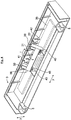
- FIG. 1 is shown in a partial view of a door 1 of a dishwasher.
- the appliance door 1 can be actuated in a known manner via a horizontal, bottom-side pivot axis, not shown, and has at the upper edge a control panel 3 made of plastic material.
- the control panel 3 limited with a flange-developed blind casing 13 on the upper side of the door unit 1 and is connected via lateral, downwardly projecting connecting pin 5 in a manner not shown with a door assembly of the door 1.
- the control panel 3 has on its front wall 7 arranged in series controls 9 and a centrally located display 11 for displaying operating conditions or the like.
- the user facing the front wall 7 of the control panel 3 goes to its opposite in the door side direction x side edges and at its upper side edge in the aperture 13. This forms on the upper edge of the door a glare roof.
- FIG. 1 Below the in the Fig. 1 shown display displays 11 is provided in an approximately rectangular shaped engagement opening 15 for an integrated in the control panel 3 grip 17.
- the grip 17 is according to the Fig. 3 executed in two parts with a shell bottom 19 and a handle shell cover 21.
- the handle shell lower part 19 delimited with a lower shell-shaped raised wall portion 23 and an opposite upper, horizontally extending grip web 25, the insertion opening 15 of the handle shell 17.
- the handle shell lower part 19 is integrally integrated with its handle bar 25 and the lower wall portion 23 in the injection molding of the control panel 3.
- the geometry of the control panel 3 and the handle shell lower part 19 is selected so that no undercuts are present in the Entformungscardi E of the injection molding tools.
- Fig. 3 Like from the Fig. 3 further shows, in the horizontal direction between the handle bar 25 and the upwardly drawn wall portion 23, a free cut formed, which is bounded by a peripheral abutment edge 27. On the contact edge 27 sits the handle shell cover 21.
- This is in the side sectional view of Fig. 3 shown in trapezoidal shape with a front side edge 29 and a rear side edge 31, which are respectively in contact with the handle bar 25 and the raised wall portion 23 of the handle shell lower part 19.
- a free mounting space 33 is provided, is guided by the according to the figures, only indicated by dashed lines electronics module 35 along the back of the control panel 3.
- the size of the mounting space 33 in the Bautiefencardi 4 is determined by the length of the handle bar 25.
- the electronic module 35 is assigned to the operating and display elements 9, 11 of the control panel 3. According to the Fig. 2 the electronic module 35 is strip-shaped and guided by the mounting space 33 of the double-wall structure 16. The electronics module 35 thus extends almost over the entire width of the appliance door. 1
- the handle shell lid 21 is supported by lateral support members 37 on support ribs 39.
- the roughly bay-like running support elements 37 are dimensioned so that in the installed position of the handle shell cover 21 are braced without play between the support ribs 42 and the abutment edge 27 of the handle shell lower part 19.
- the support ribs 42 are integrally formed on the rear panel 13 according to the figures.
- each of the support elements 37 has two shaft walls 38, which are connected to each other at the front end via an elastically yielding latching wall 39.
- the shaft walls 38 of the support members 37 are according to the Fig. 3 in the construction position positively on a contact shoulder of the support ribs 42.
- the locking walls 39 are elastically bent from its rest position. In construction position of the handle shell cover 21, the locking walls 39 jump back to their rest position, whereby the locking rib 41 engage behind the locking walls 39. In this way, the handle cover 21 is held securely in the shown construction position.
- the handle shell cover 21 is pivoted in a pivoting movement I in its construction position, which in the Fig. 2 is shown.
- the handle shell cover 21 has lateral suspension hooks 43. These are according to the Fig. 4 guided by the lateral openings 45 on the handle shell lower part 19, whereby a hinge point is formed, via which the handle shell cover 21 is pivotable into the construction position.
- the handle shell base 19 has no lateral openings 45 into which the hooks 43 can be inserted from above.
- the articulation point is designed via a guide groove 47 which is open in the depth direction, as well as a T-shaped suspension lug 49 which can be inserted therein and which is integrally formed on the handle shell cover 21.
- the laterally outer shaft walls 38 of the support elements 37 are extended downward so that they laterally overlap outer walls 40 of the handle shell lower part 19.
- the laterally downwardly extended shaft walls 38 thus serve as guide walls, with which the Einschwenkvorgang is performed in the device side direction.
Landscapes
- Washing And Drying Of Tableware (AREA)
- Casings For Electric Apparatus (AREA)
- Electric Vacuum Cleaner (AREA)
- Main Body Construction Of Washing Machines And Laundry Dryers (AREA)
- Details Of Rigid Or Semi-Rigid Containers (AREA)
- Tumbler Switches (AREA)
Description
- Die Erfindung betrifft eine Haushalts- Geschirrspülmaschine nach dem Oberbegriff des Patentanspruches 1.
- Geschirrspülmaschinen weisen üblicherweise eine frontseitige Gerätetür auf, die um eine horizontale bodenseitige Schwenkachse aufklappbar ist. Die Gerätetür kann zum Öffnen bzw. zum Schließen der Geschirrspülmaschine mit einer Griffmulde versehen sein.
- Aus der
DE 199 07 233 A1 ist eine Geschirrspülmaschine bekannt, in deren Gerätetür eine Bedienblende vorgesehen ist, in der eine Griffschale ausgebildet ist. Die Griffschale weist ein Griffschalenunterteil auf, das einstückig an der Bedienblende angeformt ist, und einen rückseitig an der Bedienblende angeordneten Griffschalendeckel auf, mit dem ein von der Griffschale bereitgestellter Eingriffsbereich umschlossen ist. - Der von der Griffmulde bereitgestellte Eingriffsbereich ist teilweise unmittelbar von der Rückseite der Bedienblende begrenzt, wodurch das Erscheinungsbild der Gerätetür sowie die Haptik bei der Türbetätigung beeinträchtigt ist. Zusätzlich kann im Bereich der Griffschale die Rückseite der Bedienblende nicht zur Anordnung von Steuerelektronik für die Anzeige- und Bedienelemente der Bedienblende genutzt werden.
- Bei der
US 5,174,618 ist am oberen Ende der Gerätetür einer Geschirrspülmaschine eine Bedienblende mit einer Eingriffsöffnung vorgesehen. In dieser ist eine Öffnungshandhabe bzw. Klinke vorgesehen, die an der Oberkante der Außentür der Gerätetür angeordnet ist und sich zum Öffnen der Gerätetür nach oben bewegen lässt. Die nach oben bewegliche Klinke weist dabei einen Bewegungsspalt zur Front der Bedienblende auf. - Die Geschirrspülmaschine der
US 2003/0168080 A1 weist gemäß derFigur 2 eine Tür auf, deren oberer Teil als ein durch die Hand eines Benutzers hintergreifbarer Griff ausgebildet ist (sieheFigur 2 ), d.h. der Griff bilden einen integralen Bestandteil der Tür. Auf der hintergreifbaren Fläche des Griffs ist ein berührungsenpfindlicher Sensor vorgesehen. - Die Aufgabe der Erfindung besteht darin, ein Haushaltsgerät mit einer Gerätetür bereitzustellen, deren Griffschale stabil sowie optisch und haptisch günstig ausgeführt ist.
- Die Aufgabe ist durch die Merkmale des Patentanspruches 1 gelöst. Vorteilhafte Weiterbildungen der Erfindung sind in den Unteransprüchen offenbart.
- Die Erfindung geht aus von einer Geschirrspülmaschine, als Haushaltsgerät mit einer Gerätetür, die eine Bedienblende mit einer Griffschale aufweist, die mindestens aus einem Griffschalenunterteil und einem Griffschalendeckel gebildet ist.
- Gemäß dem Patentanspruch 1 weist der Griffschalendeckel eine der Bedienblende zugewandte Seitenwand auf, die zusammen mit der Bedienblende eine Doppelwandstruktur mit zwischengeordnetem freien Montageraum bildet, wobei in dem Montageraum der Doppelwandstruktur ein Elektronikmodul etwa für Bedien- oder Anzeigeelemente der Bedienblende angeordnet ist.
- Mit der Doppelwandstruktur ergibt sich benutzerseitig beim Eingreifen in die Griffschale ein solider, wertiger Eindruck. Vorteilhaft kann daher ein Hintergreifen von lediglich einer einfachen Kunststoffmaterialstärke, wie es im Stand der Technik der Fall ist, vermieden werden.
- Erfindungsgemäß ist in dem freien Montageraum zwischen der Bedienblende und der Griffschalendeckel-Seitenwand ein Elektronikmodul für die von der Bedienblende getragenen Bedien- oder Anzeigeelemente angeordnet. Auf diese Weise kann unmittelbar oberhalb der Eingriffsöffnung der Griffschale in der Frontwand der Bedienblende ein Anzeigefenster für ein Display vorgesehen werden, das in einer Gerätetür-Hochrichtung zumindest teilweise die Eingriffsöffnung überragt.
- Die vollständige zusammengebaute Gerätetür weist ein, einem Nutzraum der Haushalts-Geschirrspülmaschine zugewandtes, flächiges Innentürelement auf, das mit einem tragenden Türrahmen verschraubt sein kann. Die Bedienblende kann am oberen Rand der Gerätetür auf den Türrahmen aufgesetzt sein und ebenfalls mit dem Innentürelement verschraubt sein.
- Für eine bauraumgünstige Nutzung der Rückseite der Bedienblende kann der Montageraum in der Doppelwandstruktur in einer Türseitenrichtung parallel zur Griffschalendeckel-Seitenwand bzw. zur Bedienblende offen gestaltet, so dass über nahezu der gesamten Gerätetür-Breite ein leistenförmiges Steuermodul einteilig durch den Montagezwischenraum führbar ist.
- Die in der Frontwand der Bedienblende vorgesehene Eingriffsöffnung der Griffschale kann in Tür-Hochrichtung von einem oberen Griffsteg und einem unteren schalenförmig hochgezogenen Wandabschnitt der Bedienblende begrenzt sein. Der Griffsteg und der Wandabschnitt bilden das Griffschalenunterteil. Der Griffsteg kann in Bautiefenrichtung der Gerätetür in das Türinnere einragen und die Bedienblenden-Frontwand mit der Seitenwand des Griffschalendeckels verbinden. Die Länge des Griffsteges bestimmt daher die Größe des Montageraums der Doppelwandstruktur.
- Beim Türöffnen oder beim Anheben der Haushalts- Geschirrspülmaschine über die Griffschale, etwa aus Transportgründen, wird die Bedienblende mit Verwindungskräften beansprucht. Eine formstabile steife Ausbildung der Bedienblende ist daher von Bedeutung. Vor diesem Hintergrund kann die Bedienblende-Geometrie in etwa kastenförmig oder haubenartig gestaltet sein, mit einer benutzerseitigen Frontwand mit darin integrierten Anzeige- und/oder Bedienelementen, die in einen in Bautiefenrichtung flanschartig abgewinkelten Blendenmantel übergeht.
- Bevorzugt kann der Griffschalendeckel am oberseitig verlaufenden Blendenmantel bzw. dem Blendendach abgestützt sein. Hierzu kann der Griffschalendeckel in der Gerätehochrichtung mit zumindest einem Stützelement verlängert sein, über das der Griffschalendeckel am Blendendach abstützbar ist. Der Griffschalendeckel bzw. dessen Stützelement kann so bemessen sein, dass er in Einbaulage zwischen dem Blendendach und dem Griffschalenunterteil spielfrei verspannt ist. Mit der erfindungsgemäßen Deckel-Halterung zwischen dem Griffschalenunterteil und dem Blendendach kann die Bedienblenden-Frontwand rückseitig frei von Befestigungselementen bleiben. Solche Elemente können erfindungsgemäß dagegen am Blendendach und am Griffschalenunterteil vorgesehen werden. Der Montageraum der Doppelwandstruktur bleibt daher ebenfalls frei von solchen Befestigungselementen.
- Montagetechnisch einfach ist es, wenn der Griffschalendeckel in einer Schwenkbewegung in seine Konstruktionslage bringbar ist. Hierzu kann am Griffschalenunterteil zumindest ein Anlenkpunkt vorgesehen sein, etwa eine offene Nut oder ein Durchbruch, in den der Griffschalendeckel mittels Einhängehaken eingehängt und anschließend in die Konstruktionslage geschwenkt werden kann.
- Zur Sicherung des in seiner Konstruktionslage befindlichen Griffschalendeckels kann die Bedienblende ein Sicherungselement aufweisen, um ein unbeabsichtigtes Lösen des Griffschalendeckels aus seiner Konstruktionslage zu vermeiden. Bevorzugt kann das Sicherungselement am Blendendach der Bedienblende vorgesehen sein. Das Sicherungselement kann bevorzugt eine Rastrippe sein, die nach einem Einschwenken des Griffschalendeckels das Stützelement in einer Demontagerichtung hintergreift.
- Für den Fall, dass die Haushalts-- Geschirrspülmaschine über die Griffschale angehoben wird, wirkt das Stützelement des Griffschalendeckels als eine Kraftübertragungsbrücke, über die Kräfte unmittelbar in das Blendendach der Bedienblende eingeleitet werden, ohne Befestigungselemente des Griffschalendeckels zu belasten.
- Eine weitere Montagevereinfachung ergibt sich, wenn der Griffschalendeckel zusätzliche seitliche Führungswände aufweist, die beim Einbau entlang von korrespondierenden Außenwänden des Griffschalenunterteils geführt werden können, wodurch der Griffschalendeckel beim Einbau vorzentriert wird.
- Nachfolgend ist ein Ausführungsbeispiel der Erfindung anhand der beigefügten Figuren gezeigt.
- Es zeigen:
- Fig. 1
- in einer perspektivischen Teilansicht eine Gerätetür einer Geschirrspülmaschine;
- Fig. 2
- in einer Alleinstellung eine rückseitige Ansicht der Bedienblende der Gerätetür;
- Fig. 3
- in einer Schnittdarstellung entlang der Schnittebene I-I aus der
Fig. 2 die Bedienblende; - Fig. 4
- eine der
Fig. 2 entsprechende Ansicht zur Veranschaulichung der Montage der Griffschalendeckels; und - Fig. 5
- in einer Abwandlung einen Anlenkpunkt am Griffschalenunterteil zur Montage des Griffschalendeckels.
- In der
Fig. 1 ist in einer Teilansicht eine Gerätetür 1 einer Geschirrspülmaschine gezeigt. Die Gerätetür 1 ist in bekannter Weise über eine nicht dargestellte, horizontale bodenseitige Schwenkachse betätigbar und weist am oberen Rand eine aus Kunststoffmaterial gefertigte Bedienblende 3 auf. Die Bedienblende 3 begrenzt mit einem flanschartig abgewickelten Blendenmantel 13 oberseitig die Gerätetür 1 und ist über seitliche, nach unten ragende Verbindungszapfen 5 in nicht näher dargestellter Weise mit einem Türaufbau der Gerätetür 1 verbunden. Die Bedienblende 3 weist an ihrer Frontwand 7 in Reihe angeordnete Bedienelemente 9 sowie ein zentral gelegenes Anzeigedisplay 11 zur Anzeige von Betriebszuständen oder dergleichen auf. - Die dem Benutzer zugewandte Frontwand 7 der Bedienblende 3 geht an ihren in der Türseitenrichtung x gegenüberliegenden Seitenrändern sowie an ihren oberen Seitenrand in den Blendenmantel 13 über. Dieser bildet am oberen Türrand ein Blendendach.
- Unterhalb des in der
Fig. 1 dargestellten Anzeigedisplays 11 ist eine in etwa rechteckförmig gestaltete Eingriffsöffnung 15 für eine in der Bedienblende 3 integrierte Griffschale 17 vorgesehen. Die Griffschale 17 ist gemäß derFig. 3 zweiteilig mit einem Schalenunterteil 19 und einem Griffschalendeckel 21 ausgeführt. Das Griffschalenunterteil 19 begrenzt mit einem unteren schalenförmig hochgezogenen Wandabschnitt 23 und einem gegenüberliegenden oberen, horizontal verlaufenden Griffsteg 25 die Einführöffnung 15 der Griffschale 17. Das Griffschalenunterteil 19 ist zusammen mit seinem Griffsteg 25 sowie dem unteren Wandabschnitt 23 einstückig im Spritzgussverfahren an der Bedienblende 3 integriert. Die Geometrie der Bedienblende 3 sowie des Griffschalenunterteils 19 ist so gewählt, dass in der Entformungsrichtung E der Spritzgusswerkzeuge keine Hinterschneidungen vorhanden sind. - Wie aus der
Fig. 3 weiter hervorgeht, ist in Horizontalrichtung zwischen dem Griffsteg 25 und dem nach oben gezogenen Wandabschnitt 23 ein freier Ausschnitt gebildet, der von einem umlaufenden Anlagekante 27 begrenzt ist. Auf der Anlagekante 27 sitzt der Griffschalendeckel 21. Dieser ist in der Seitenschnittdarstellung derFig. 3 in etwa trapezförmig mit einer vorderen Seitenflanke 29 und einer hinteren Seitenflanke 31 dargestellt, die jeweils in Anlage mit dem Griffsteg 25 bzw. dem hochgezogenen Wandabschnitt 23 des Griffschalenunterteiles 19 sind. Die Seitenflanke 29 des Griffschalendeckels 21 bildet zusammen mit der Bedienblenden-Frontwand 7 im Bereich oberhalb der Eingriffsöffnung 15 eine Doppelwandstruktur 16 mit quer verlaufendem Griffsteg 25. Dieser verbindet die beiden Wände, d. h. Frontwand 7 und Seitenflanke 29, miteinander. Zwischen der Seitenflanke 29 des Griffschalendeckels 21 und der Frontwand 7 der Bedienblende 3 ist ein freier Montagezwischenraum 33 vorhanden, durch den gemäß den Figuren ein nur gestrichelt angedeutetes Elektronikmodul 35 entlang der Rückseite der Bedienblende 3 geführt ist. Die Größe des Montageraums 33 in der Bautiefenrichtung 4 wird durch die Länge des Griffsteges 25 festgelegt. - Das Elektronikmodul 35 ist den Bedien- und Anzeigeelementen 9, 11 der Bedienblende 3 zugeordnet. Gemäß der
Fig. 2 ist das Elektronikmodul 35 leistenförmig ausgeführt und durch den Montageraum 33 der Doppelwandstruktur 16 geführt. Das Elektronikmodul 35 erstreckt sich somit nahezu über die gesamte Breite der Gerätetür 1. - Wie aus den
Fig. 2 und3 weiter hervorgeht, ist der Griffschalendeckel 21 über seitliche Stützelemente 37 an Stützrippen 39 abgestützt. Die in etwa schachtartig ausgeführten Stützelemente 37 sind so bemessen, dass in der gezeigten Einbaulage der Griffschalendeckel 21 spielfrei zwischen den Stützrippen 42 und der Anlagekante 27 des Griffschalenunterteiles 19 verspannt sind. Die Stützrippen 42 sind gemäß den Figuren rückseitig an dem Blendendach 13 angeformt. - Gemäß der
Fig. 2 weist jedes der Stützelemente 37 zwei Schachtwände 38 auf, die stirnseitig über eine elastisch nachgiebige Rastwand 39 miteinander verbunden sind. - Die Schachtwände 38 der Stützelemente 37 liegen gemäß der
Fig. 3 in der Konstruktionslage formschlüssig auf einer Anlageschulter der Stützrippen 42 auf. Beim Einschwenken des Griffschalendeckels 21 gemäß derFig. 4 werden die elastisch nachgiebigen Rastwände 39 der Stützelemente 37 an Rastrippen 41 vorbeigeführt. Die Rastwände 39 werden dabei elastisch aus ihrer Ruhelage gebogen. In Konstruktionslage des Griffschalendeckels 21 springen die Rastwände 39 in ihre Ruhelage zurück, wodurch die Rastrippe 41 die Rastwände 39 hintergreifen. Auf diese Weise ist der Griffschalen-Deckel 21 lagesicher in der gezeigten Konstruktionslage festgehalten. - Anhand der
Fig. 4 ist nachfolgend die Montage des Griffschalendeckels 21 an der Bedienblende 3 beschrieben. Demzufolge wird der Griffschalendeckel 21 in einer Schwenkbewegung I in seine Konstruktionslage geschwenkt, die in derFig. 2 gezeigt ist. Zur Ausführung der Schwenkbewegung weist der Griffschalendeckel 21 seitliche Einhängehaken 43 auf. Diese werden gemäß derFig. 4 durch die seitlichen Durchbrüche 45 am Griffschalenunterteil 19 geführt, wodurch ein Gelenkpunkt gebildet ist, über den der Griffschalendeckel 21 in die Konstruktionslage schwenkbar ist. - In der
Fig. 5 ist in einer Abwandlung eine alternative Ausführung des Griffschalenunterteiles 19 gezeigt. Demzufolge weist das Griffschalenunterteil 19 keine seitlichen Durchbrüche 45 auf, in die die Einhängehaken 43 von oben einsteckbar ist. Im Unterschied zu den vorangegangenen Figuren ist der Gelenkpunkt über eine in Bautiefenrichtung offene Führungsnut 47 sowie eine darin einschiebbare T-förmige Einhängelasche 49 ausgeführt, die am Griffschalendeckel 21 angeformt ist. - Gemäß den
Fig. 2 und4 sind die jeweils seitlich äußeren Schachtwände 38 der Stützelemente 37 nach unten verlängert, so dass diese seitlich äußere Wände 40 des Griffschalenunterteiles 19 überlappen. Die seitlich nach unten verlängerten Schachtwände 38 dienen somit als Führungswände, mit denen der Einschwenkvorgang in Geräteseitenrichtung geführt ist.BEZUGSZEICHENLISTE 1 Gerätetür l Schwenkbewegungsrichtung 3 Bedienblende x Geräteseitenrichtung 5 Verbindungszapfen y Bautiefenrichtung 7 Frontwand der Bedienblende 3 z Vertikalrichtung 9 Bedienelemente 11 Anzeigedisplay 13 Blendendach 15 Eingriffsöffnung 17 Griffschale 19 Griffschalenunterteil 21 Griffschalendeckel 23 hochgezogener Wandabschnitt 25 Griffsteg 27 Anlagekante 29 vordere Seitenflanke 31 hintere Seitenflanke 33 Montageraum 35 Elektronikmodul 37 Stützelemente 38 Stützwände 39 Rastwand 41 Rastrippen 42 Stützrippen 43 Einhängehaken 45 Durchbruch 47 Führungsnut 49 T-förmige Einhängelasche 40 Seitenwände der Griffschale 17 E Entformungsrichtung
Claims (11)
- Haushalts- Geschirrspülmaschine mit einer Gerätetür (1), die eine Bedienblende (3) mit einer Griffschale (17) aufweist, die mindestens aus einem Griffschalenunterteil (19) und einem Griffschalendeckel (21) gebildet ist, dadurch gekennzeichnet, dass der Griffschalendeckel (21) eine der Bedienblende (3) zugewandte Seitenwand (29) aufweist, die zusammen mit der Bedienblende (3) eine Doppelwandstruktur (16) mit zwischengeordnetem freien Montageraum (33) bildet, wobei in dem Montageraum (33) der Doppelwandstruktur ein Elektronikmodul (35) etwa für Bedien- oder Anzeigeelemente (9, 11) der Bedienblende (3) angeordnet ist.
- Haushalts- Geschirrspülmaschine nach Anspruch 1, dadurch gekennzeichnet, dass der Montageraum (33) in einer Türseitenrichtung (x) parallel zur Griffschalendeckel-Seitenwand (29) bzw. zur Bedienblende (3) offen gestaltet ist.
- Haushalts- Geschirrspülmaschine nach Anspruch 1 oder 2, dadurch gekennzeichnet, dass die Bedienblende (3) eine benutzerseitige Frontwand (7) mit darin integrierten Anzeige- und/oder Bedienelementen (9, 11) und ein davon in einer Bautiefenrichtung (y) der Gerätetür (1) flanschartig abgewinkeltes Blendendach (13) aufweist.
- Haushalts- Geschirrspülmaschine nach Anspruch 3, dadurch gekennzeichnet, dass der Griffschalendeckel (21) zwischen dem Griffschalenunterteil (19) und dem Blendendach (13) abgestützt ist, und insbesondere der Griffschalendeckel (21) zumindest ein Stützelement (37) aufweist, über das der Griffschalendeckel (21) am Blendendach (13) abgestützt ist.
- Haushalts- Geschirrspülmaschine nach Anspruch 4, dadurch gekennzeichnet, dass das Griffschalenunterteil (19) zumindest einen Anlenkpunkt, insbesondere eine offene Nut (47) oder einen Durchbruch (45), aufweist, um den der Griffschalendeckel (21) beim Einbau in seine Konstruktionslage schwenkbar ist.
- Haushalts- Geschirrspülmaschine nach einem der vorhandenen Ansprüche, dadurch gekennzeichnet, dass dem Griffschalendeckel (21) ein Sicherungselement (41) zur Sicherung des Deckels (21) in seiner Konstruktionslage zugeordnet ist.
- Haushalts- Geschirrspülmaschine nach Anspruch 6, dadurch gekennzeichnet, dass das Sicherungselement (41) am Blendendach (13) der Bedienblende (3) vorgesehen ist, welches Sicherungselement (41) insbesondere ein Rastelement ist, das nach erfolgten Einschwenken des Griffschalendeckels (21) in die Konstruktionslage dessen Stützelement (37) hintergreift.
- Haushalts- Geschirrspülmaschine nach einem der vorhergehenden Ansprüche, dadurch gekennzeichnet, dass oberhalb einer Eingriffsöffnung (15) der Griffschale (17) ein Anzeigefenster (11) in der Frontwand (7) der Bedienblende (3) vorgesehen ist.
- Haushalts- Geschirrspülmaschine nach einem der vorhergehenden Ansprüche, dadurch gekennzeichnet, dass der Griffschalendeckel (21) seitliche Führungswände (38) aufweist, die beim Einbau entlang von korrespondierenden Außenwänden (40) des Griffschalenunterteils (19) geführt sind.
- Haushalts- Geschirrspülmaschine nach einem der vorhergehenden Ansprüche, dadurch gekennzeichnet, dass die Doppelwandstruktur einen quer verlaufenden Griffsteg (25) aufweist, der die Bedienblende (3) mit der Seitenwand (29) des Griffschalendeckels (21) verbindet.
- Haushalts- Geschirrspülmaschine t nach Anspruch 10, dadurch gekennzeichnet, dass der Griffsteg (25) die Eingriffsöffnung (15) der Griffschale (17) begrenzt.
Priority Applications (1)
| Application Number | Priority Date | Filing Date | Title |
|---|---|---|---|
| PL09764491T PL2379794T3 (pl) | 2008-12-19 | 2009-11-30 | Zmywarka do naczyń gospodarstwa domowego |
Applications Claiming Priority (2)
| Application Number | Priority Date | Filing Date | Title |
|---|---|---|---|
| DE102008055029.9A DE102008055029C5 (de) | 2008-12-19 | 2008-12-19 | Haushaltsgerät, insbesondere Geschirrspülmaschine |
| PCT/EP2009/066013 WO2010069738A1 (de) | 2008-12-19 | 2009-11-30 | Haushaltsgerät, insbesondere geschirrspülmaschine |
Publications (2)
| Publication Number | Publication Date |
|---|---|
| EP2379794A1 EP2379794A1 (de) | 2011-10-26 |
| EP2379794B1 true EP2379794B1 (de) | 2019-04-10 |
Family
ID=41722783
Family Applications (1)
| Application Number | Title | Priority Date | Filing Date |
|---|---|---|---|
| EP09764491.8A Active EP2379794B1 (de) | 2008-12-19 | 2009-11-30 | Haushalts-geschirrspülmaschine |
Country Status (8)
| Country | Link |
|---|---|
| US (1) | US9005371B2 (de) |
| EP (1) | EP2379794B1 (de) |
| CN (1) | CN102257205B (de) |
| DE (1) | DE102008055029C5 (de) |
| PL (1) | PL2379794T3 (de) |
| RU (1) | RU2541497C2 (de) |
| TR (1) | TR201906021T4 (de) |
| WO (1) | WO2010069738A1 (de) |
Families Citing this family (20)
| Publication number | Priority date | Publication date | Assignee | Title |
|---|---|---|---|---|
| DE102011007870A1 (de) | 2011-04-21 | 2012-10-25 | BSH Bosch und Siemens Hausgeräte GmbH | Gerätetür für ein Haushaltsgerät und Haushaltsgerät |
| US9408519B2 (en) * | 2012-11-27 | 2016-08-09 | Whirlpool Corporation | Dishwasher support structures to reduce rotation of a door crown |
| DE102014217238B4 (de) * | 2014-08-28 | 2025-02-27 | BSH Hausgeräte GmbH | Geschirrspülmaschine mit einer Bedienblende und einer Eingriffsöffnung |
| DE102014217210B4 (de) * | 2014-08-28 | 2023-11-30 | BSH Hausgeräte GmbH | Geschirrspülmaschine mit zumindest einer Bedienblende |
| DE102014217222B4 (de) * | 2014-08-28 | 2025-02-27 | BSH Hausgeräte GmbH | Geschirrspülmaschine mit einer Bedienblende |
| US9803389B2 (en) | 2015-10-06 | 2017-10-31 | Bsh Home Appliances Corporation | Handle tray for fascia panel of an appliance |
| WO2017059907A1 (en) * | 2015-10-08 | 2017-04-13 | Arcelik Anonim Sirketi | Drawer assembly for a laundry machine |
| US9775489B1 (en) | 2016-03-31 | 2017-10-03 | Whirlpool Corporation | Door assembly for a dishwasher |
| USD803491S1 (en) | 2016-09-12 | 2017-11-21 | Whirlpool Corporation | Dishwasher handle |
| US10036181B2 (en) * | 2016-11-14 | 2018-07-31 | Whirlpool Corporation | Household appliance having a pocket handle and associated display |
| USD887653S1 (en) | 2017-08-31 | 2020-06-16 | Whirlpool Corporation | Dishwasher door and control panel |
| US10869589B2 (en) | 2017-08-31 | 2020-12-22 | Whirlpool Corporation | Dish treating appliance door assembly |
| CN109898923A (zh) * | 2017-12-11 | 2019-06-18 | 青岛海尔智慧厨房电器有限公司 | 一种把手结构 |
| CN109965709B (zh) * | 2017-12-28 | 2023-11-17 | 宁波方太厨具有限公司 | 一种家用电器的门体结构 |
| US20190223685A1 (en) * | 2018-01-23 | 2019-07-25 | Haier Us Appliance Solutions, Inc. | Door for a dishwasher appliance |
| USD939157S1 (en) | 2018-07-18 | 2021-12-21 | Whirlpool Corporation | Top cap combined with front control for a door panel of a dish treating appliance |
| US11134826B2 (en) | 2018-08-20 | 2021-10-05 | Haier Us Appliance Solutions, Inc. | Status indicator and lighting assembly for an appliance door |
| US10478040B1 (en) | 2018-08-20 | 2019-11-19 | Haier Us Appliance Solutions, Inc. | Handle assembly for an appliance door |
| US11839339B2 (en) | 2021-08-05 | 2023-12-12 | Haier Us Appliance Solutions, Inc. | Pocket handle assembly for an appliance |
| US11849898B2 (en) * | 2021-08-26 | 2023-12-26 | Whirlpool Corporation | Dishwasher with door assembly |
Citations (5)
| Publication number | Priority date | Publication date | Assignee | Title |
|---|---|---|---|---|
| DE3314681A1 (de) | 1983-04-22 | 1984-10-25 | Licentia Patent-Verwaltungs-Gmbh, 6000 Frankfurt | Geraetetuer |
| US5174618A (en) | 1991-12-09 | 1992-12-29 | Maytag Corporation | Door latch assembly |
| EP1321092A2 (de) | 2001-12-12 | 2003-06-25 | Electrolux Home Products Corporation N.V. | Geschirrspülmaschine |
| US20030168080A1 (en) | 2002-03-07 | 2003-09-11 | Raches Scott D. | Fast interrupt of dishwasher hand sensor |
| JP2006194545A (ja) | 2005-01-14 | 2006-07-27 | Toshiba Corp | 冷蔵庫扉 |
Family Cites Families (9)
| Publication number | Priority date | Publication date | Assignee | Title |
|---|---|---|---|---|
| DE19757809A1 (de) * | 1997-12-24 | 1999-07-08 | Aeg Hausgeraete Gmbh | Haushaltsgerät mit einer Bedienblendeneinheit |
| DE19859980A1 (de) * | 1998-12-23 | 2000-06-29 | Bsh Bosch Siemens Hausgeraete | Haushaltgerät mit einem Bedienfeld |
| DE19907233A1 (de) * | 1999-02-19 | 2000-08-24 | Aeg Hausgeraete Gmbh | Geschirrspülmaschine mit einem Türschloß |
| DE10045236B4 (de) * | 2000-09-13 | 2013-08-22 | BSH Bosch und Siemens Hausgeräte GmbH | Geschirrspülmaschine für den Einbau hinter einer Möbelfrontplatte |
| JP3336000B1 (ja) * | 2001-04-25 | 2002-10-21 | 株式会社日立製作所 | 冷蔵庫 |
| DE10133766B4 (de) * | 2001-07-11 | 2004-07-01 | AEG Hausgeräte GmbH | Betätigungsvorrichtung für einen Türverschluss |
| DE10200317B4 (de) * | 2002-01-07 | 2005-01-27 | BSH Bosch und Siemens Hausgeräte GmbH | Bedien- und Elektronikmodul eines elektrischen Haushaltsgeräts |
| JP4276987B2 (ja) | 2004-09-06 | 2009-06-10 | 日立アプライアンス株式会社 | 冷蔵庫 |
| DE102004062752A1 (de) * | 2004-12-27 | 2006-07-06 | BSH Bosch und Siemens Hausgeräte GmbH | Integriertes Betriebsanzeigeelement |
-
2008
- 2008-12-19 DE DE102008055029.9A patent/DE102008055029C5/de active Active
-
2009
- 2009-11-30 WO PCT/EP2009/066013 patent/WO2010069738A1/de not_active Ceased
- 2009-11-30 PL PL09764491T patent/PL2379794T3/pl unknown
- 2009-11-30 EP EP09764491.8A patent/EP2379794B1/de active Active
- 2009-11-30 RU RU2011125654/12A patent/RU2541497C2/ru active
- 2009-11-30 CN CN200980151155.2A patent/CN102257205B/zh active Active
- 2009-11-30 US US13/132,324 patent/US9005371B2/en active Active
- 2009-11-30 TR TR2019/06021T patent/TR201906021T4/tr unknown
Patent Citations (5)
| Publication number | Priority date | Publication date | Assignee | Title |
|---|---|---|---|---|
| DE3314681A1 (de) | 1983-04-22 | 1984-10-25 | Licentia Patent-Verwaltungs-Gmbh, 6000 Frankfurt | Geraetetuer |
| US5174618A (en) | 1991-12-09 | 1992-12-29 | Maytag Corporation | Door latch assembly |
| EP1321092A2 (de) | 2001-12-12 | 2003-06-25 | Electrolux Home Products Corporation N.V. | Geschirrspülmaschine |
| US20030168080A1 (en) | 2002-03-07 | 2003-09-11 | Raches Scott D. | Fast interrupt of dishwasher hand sensor |
| JP2006194545A (ja) | 2005-01-14 | 2006-07-27 | Toshiba Corp | 冷蔵庫扉 |
Also Published As
| Publication number | Publication date |
|---|---|
| DE102008055029A1 (de) | 2010-07-01 |
| RU2541497C2 (ru) | 2015-02-20 |
| CN102257205B (zh) | 2014-08-20 |
| DE102008055029C5 (de) | 2016-04-14 |
| WO2010069738A1 (de) | 2010-06-24 |
| PL2379794T3 (pl) | 2019-09-30 |
| EP2379794A1 (de) | 2011-10-26 |
| DE102008055029B4 (de) | 2013-12-05 |
| CN102257205A (zh) | 2011-11-23 |
| RU2011125654A (ru) | 2013-01-27 |
| TR201906021T4 (tr) | 2019-05-21 |
| US20110247276A1 (en) | 2011-10-13 |
| US9005371B2 (en) | 2015-04-14 |
Similar Documents
| Publication | Publication Date | Title |
|---|---|---|
| EP2379794B1 (de) | Haushalts-geschirrspülmaschine | |
| DE102006019959B4 (de) | Tankklappe für Automobile | |
| DE102016224755A1 (de) | Haushaltsgargerät | |
| DE102007057513A1 (de) | Haushaltsgerät, insbesondere Geschirrspülmaschine | |
| EP2553343B2 (de) | Ofentüre, sowie verfahren zum befestigen eines türabdeckteils an einer derartigen ofentüre | |
| EP2514350B1 (de) | Gerätetür für ein Haushaltsgerät und Haushaltsgerät | |
| EP2181290B1 (de) | Haushaltsgerätetür mit einer vorrichtung zum verbinden von glasscheiben | |
| EP2290308B1 (de) | Kältegerät | |
| EP2675970B1 (de) | Türgriff für eine haushaltsgerätetür | |
| DE102010063448A1 (de) | Geschirrspülmaschine | |
| EP1722667B1 (de) | Haushaltsgrossgerät mit einer durch einen griff bewegbaren tür, insbesondere für geschirrspülmaschinen | |
| EP2420177B1 (de) | Geschirrspülmaschine, insbesondere Haushalts-Geschirrspülmaschine | |
| DE3448057C2 (de) | ||
| EP2464927B1 (de) | Türeinbauteil für ein kältegerät | |
| DE102008054498A1 (de) | Gehäuse für ein Haushaltsgerät | |
| WO2009027345A1 (de) | Haushaltsstandgerät mit einer kippschutzvorrichtung | |
| EP1216648B1 (de) | Tür für Haushaltgeräte | |
| DE102008041559B4 (de) | Kältegerät | |
| EP2010021A2 (de) | Möbelanordnung für einbaugeräte | |
| DE102008042944B4 (de) | Geschirrspülmaschine mit einem Frontelement | |
| EP2328454A2 (de) | Geschirrspülmaschine zum einbau in einen einbauschrank | |
| EP2280235B1 (de) | Korpus für ein Haushaltsgerät | |
| EP2132845B1 (de) | Schaltpult | |
| DE60207673T2 (de) | Vorrichtung zum Freigeben einer Schwenktürverkleidung | |
| EP2607545B1 (de) | Blende, insbesondere für Haushaltgeräte |
Legal Events
| Date | Code | Title | Description |
|---|---|---|---|
| PUAI | Public reference made under article 153(3) epc to a published international application that has entered the european phase |
Free format text: ORIGINAL CODE: 0009012 |
|
| 17P | Request for examination filed |
Effective date: 20110719 |
|
| AK | Designated contracting states |
Kind code of ref document: A1 Designated state(s): AT BE BG CH CY CZ DE DK EE ES FI FR GB GR HR HU IE IS IT LI LT LU LV MC MK MT NL NO PL PT RO SE SI SK SM TR |
|
| RIN1 | Information on inventor provided before grant (corrected) |
Inventor name: SCHESSL, BERND Inventor name: GERSTNER, NORBERT Inventor name: EGGER, GERHARD Inventor name: SCHILLING, RAINER |
|
| DAX | Request for extension of the european patent (deleted) | ||
| RAP1 | Party data changed (applicant data changed or rights of an application transferred) |
Owner name: BSH HAUSGERAETE GMBH |
|
| 17Q | First examination report despatched |
Effective date: 20161006 |
|
| STAA | Information on the status of an ep patent application or granted ep patent |
Free format text: STATUS: EXAMINATION IS IN PROGRESS |
|
| GRAP | Despatch of communication of intention to grant a patent |
Free format text: ORIGINAL CODE: EPIDOSNIGR1 |
|
| STAA | Information on the status of an ep patent application or granted ep patent |
Free format text: STATUS: GRANT OF PATENT IS INTENDED |
|
| INTG | Intention to grant announced |
Effective date: 20181220 |
|
| GRAS | Grant fee paid |
Free format text: ORIGINAL CODE: EPIDOSNIGR3 |
|
| GRAA | (expected) grant |
Free format text: ORIGINAL CODE: 0009210 |
|
| STAA | Information on the status of an ep patent application or granted ep patent |
Free format text: STATUS: THE PATENT HAS BEEN GRANTED |
|
| AK | Designated contracting states |
Kind code of ref document: B1 Designated state(s): AT BE BG CH CY CZ DE DK EE ES FI FR GB GR HR HU IE IS IT LI LT LU LV MC MK MT NL NO PL PT RO SE SI SK SM TR |
|
| REG | Reference to a national code |
Ref country code: GB Ref legal event code: FG4D Free format text: NOT ENGLISH |
|
| REG | Reference to a national code |
Ref country code: CH Ref legal event code: EP Ref country code: AT Ref legal event code: REF Ref document number: 1118778 Country of ref document: AT Kind code of ref document: T Effective date: 20190415 |
|
| REG | Reference to a national code |
Ref country code: IE Ref legal event code: FG4D Free format text: LANGUAGE OF EP DOCUMENT: GERMAN |
|
| REG | Reference to a national code |
Ref country code: DE Ref legal event code: R096 Ref document number: 502009015705 Country of ref document: DE |
|
| REG | Reference to a national code |
Ref country code: NL Ref legal event code: MP Effective date: 20190410 |
|
| REG | Reference to a national code |
Ref country code: LT Ref legal event code: MG4D |
|
| PG25 | Lapsed in a contracting state [announced via postgrant information from national office to epo] |
Ref country code: NL Free format text: LAPSE BECAUSE OF FAILURE TO SUBMIT A TRANSLATION OF THE DESCRIPTION OR TO PAY THE FEE WITHIN THE PRESCRIBED TIME-LIMIT Effective date: 20190410 |
|
| PG25 | Lapsed in a contracting state [announced via postgrant information from national office to epo] |
Ref country code: FI Free format text: LAPSE BECAUSE OF FAILURE TO SUBMIT A TRANSLATION OF THE DESCRIPTION OR TO PAY THE FEE WITHIN THE PRESCRIBED TIME-LIMIT Effective date: 20190410 Ref country code: NO Free format text: LAPSE BECAUSE OF FAILURE TO SUBMIT A TRANSLATION OF THE DESCRIPTION OR TO PAY THE FEE WITHIN THE PRESCRIBED TIME-LIMIT Effective date: 20190710 Ref country code: PT Free format text: LAPSE BECAUSE OF FAILURE TO SUBMIT A TRANSLATION OF THE DESCRIPTION OR TO PAY THE FEE WITHIN THE PRESCRIBED TIME-LIMIT Effective date: 20190910 Ref country code: HR Free format text: LAPSE BECAUSE OF FAILURE TO SUBMIT A TRANSLATION OF THE DESCRIPTION OR TO PAY THE FEE WITHIN THE PRESCRIBED TIME-LIMIT Effective date: 20190410 Ref country code: SE Free format text: LAPSE BECAUSE OF FAILURE TO SUBMIT A TRANSLATION OF THE DESCRIPTION OR TO PAY THE FEE WITHIN THE PRESCRIBED TIME-LIMIT Effective date: 20190410 Ref country code: ES Free format text: LAPSE BECAUSE OF FAILURE TO SUBMIT A TRANSLATION OF THE DESCRIPTION OR TO PAY THE FEE WITHIN THE PRESCRIBED TIME-LIMIT Effective date: 20190410 Ref country code: LT Free format text: LAPSE BECAUSE OF FAILURE TO SUBMIT A TRANSLATION OF THE DESCRIPTION OR TO PAY THE FEE WITHIN THE PRESCRIBED TIME-LIMIT Effective date: 20190410 |
|
| PG25 | Lapsed in a contracting state [announced via postgrant information from national office to epo] |
Ref country code: LV Free format text: LAPSE BECAUSE OF FAILURE TO SUBMIT A TRANSLATION OF THE DESCRIPTION OR TO PAY THE FEE WITHIN THE PRESCRIBED TIME-LIMIT Effective date: 20190410 Ref country code: BG Free format text: LAPSE BECAUSE OF FAILURE TO SUBMIT A TRANSLATION OF THE DESCRIPTION OR TO PAY THE FEE WITHIN THE PRESCRIBED TIME-LIMIT Effective date: 20190710 Ref country code: GR Free format text: LAPSE BECAUSE OF FAILURE TO SUBMIT A TRANSLATION OF THE DESCRIPTION OR TO PAY THE FEE WITHIN THE PRESCRIBED TIME-LIMIT Effective date: 20190711 |
|
| PG25 | Lapsed in a contracting state [announced via postgrant information from national office to epo] |
Ref country code: IS Free format text: LAPSE BECAUSE OF FAILURE TO SUBMIT A TRANSLATION OF THE DESCRIPTION OR TO PAY THE FEE WITHIN THE PRESCRIBED TIME-LIMIT Effective date: 20190810 |
|
| REG | Reference to a national code |
Ref country code: DE Ref legal event code: R026 Ref document number: 502009015705 Country of ref document: DE |
|
| PLBI | Opposition filed |
Free format text: ORIGINAL CODE: 0009260 |
|
| PLAX | Notice of opposition and request to file observation + time limit sent |
Free format text: ORIGINAL CODE: EPIDOSNOBS2 |
|
| PG25 | Lapsed in a contracting state [announced via postgrant information from national office to epo] |
Ref country code: SK Free format text: LAPSE BECAUSE OF FAILURE TO SUBMIT A TRANSLATION OF THE DESCRIPTION OR TO PAY THE FEE WITHIN THE PRESCRIBED TIME-LIMIT Effective date: 20190410 Ref country code: DK Free format text: LAPSE BECAUSE OF FAILURE TO SUBMIT A TRANSLATION OF THE DESCRIPTION OR TO PAY THE FEE WITHIN THE PRESCRIBED TIME-LIMIT Effective date: 20190410 Ref country code: EE Free format text: LAPSE BECAUSE OF FAILURE TO SUBMIT A TRANSLATION OF THE DESCRIPTION OR TO PAY THE FEE WITHIN THE PRESCRIBED TIME-LIMIT Effective date: 20190410 Ref country code: RO Free format text: LAPSE BECAUSE OF FAILURE TO SUBMIT A TRANSLATION OF THE DESCRIPTION OR TO PAY THE FEE WITHIN THE PRESCRIBED TIME-LIMIT Effective date: 20190410 Ref country code: CZ Free format text: LAPSE BECAUSE OF FAILURE TO SUBMIT A TRANSLATION OF THE DESCRIPTION OR TO PAY THE FEE WITHIN THE PRESCRIBED TIME-LIMIT Effective date: 20190410 |
|
| 26 | Opposition filed |
Opponent name: ELECTROLUX APPLIANCES AKTIEBOLAG Effective date: 20200110 |
|
| PG25 | Lapsed in a contracting state [announced via postgrant information from national office to epo] |
Ref country code: IT Free format text: LAPSE BECAUSE OF FAILURE TO SUBMIT A TRANSLATION OF THE DESCRIPTION OR TO PAY THE FEE WITHIN THE PRESCRIBED TIME-LIMIT Effective date: 20190410 Ref country code: SM Free format text: LAPSE BECAUSE OF FAILURE TO SUBMIT A TRANSLATION OF THE DESCRIPTION OR TO PAY THE FEE WITHIN THE PRESCRIBED TIME-LIMIT Effective date: 20190410 |
|
| PLBB | Reply of patent proprietor to notice(s) of opposition received |
Free format text: ORIGINAL CODE: EPIDOSNOBS3 |
|
| PG25 | Lapsed in a contracting state [announced via postgrant information from national office to epo] |
Ref country code: SI Free format text: LAPSE BECAUSE OF FAILURE TO SUBMIT A TRANSLATION OF THE DESCRIPTION OR TO PAY THE FEE WITHIN THE PRESCRIBED TIME-LIMIT Effective date: 20190410 |
|
| REG | Reference to a national code |
Ref country code: CH Ref legal event code: PL |
|
| PG25 | Lapsed in a contracting state [announced via postgrant information from national office to epo] |
Ref country code: LU Free format text: LAPSE BECAUSE OF NON-PAYMENT OF DUE FEES Effective date: 20191130 Ref country code: MC Free format text: LAPSE BECAUSE OF FAILURE TO SUBMIT A TRANSLATION OF THE DESCRIPTION OR TO PAY THE FEE WITHIN THE PRESCRIBED TIME-LIMIT Effective date: 20190410 Ref country code: LI Free format text: LAPSE BECAUSE OF NON-PAYMENT OF DUE FEES Effective date: 20191130 Ref country code: CH Free format text: LAPSE BECAUSE OF NON-PAYMENT OF DUE FEES Effective date: 20191130 |
|
| REG | Reference to a national code |
Ref country code: BE Ref legal event code: MM Effective date: 20191130 |
|
| GBPC | Gb: european patent ceased through non-payment of renewal fee |
Effective date: 20191130 |
|
| PG25 | Lapsed in a contracting state [announced via postgrant information from national office to epo] |
Ref country code: FR Free format text: LAPSE BECAUSE OF NON-PAYMENT OF DUE FEES Effective date: 20191130 Ref country code: GB Free format text: LAPSE BECAUSE OF NON-PAYMENT OF DUE FEES Effective date: 20191130 Ref country code: IE Free format text: LAPSE BECAUSE OF NON-PAYMENT OF DUE FEES Effective date: 20191130 |
|
| PG25 | Lapsed in a contracting state [announced via postgrant information from national office to epo] |
Ref country code: BE Free format text: LAPSE BECAUSE OF NON-PAYMENT OF DUE FEES Effective date: 20191130 |
|
| REG | Reference to a national code |
Ref country code: AT Ref legal event code: MM01 Ref document number: 1118778 Country of ref document: AT Kind code of ref document: T Effective date: 20191130 |
|
| PG25 | Lapsed in a contracting state [announced via postgrant information from national office to epo] |
Ref country code: AT Free format text: LAPSE BECAUSE OF NON-PAYMENT OF DUE FEES Effective date: 20191130 |
|
| PG25 | Lapsed in a contracting state [announced via postgrant information from national office to epo] |
Ref country code: CY Free format text: LAPSE BECAUSE OF FAILURE TO SUBMIT A TRANSLATION OF THE DESCRIPTION OR TO PAY THE FEE WITHIN THE PRESCRIBED TIME-LIMIT Effective date: 20190410 |
|
| PLCK | Communication despatched that opposition was rejected |
Free format text: ORIGINAL CODE: EPIDOSNREJ1 |
|
| PG25 | Lapsed in a contracting state [announced via postgrant information from national office to epo] |
Ref country code: HU Free format text: LAPSE BECAUSE OF FAILURE TO SUBMIT A TRANSLATION OF THE DESCRIPTION OR TO PAY THE FEE WITHIN THE PRESCRIBED TIME-LIMIT; INVALID AB INITIO Effective date: 20091130 Ref country code: MT Free format text: LAPSE BECAUSE OF FAILURE TO SUBMIT A TRANSLATION OF THE DESCRIPTION OR TO PAY THE FEE WITHIN THE PRESCRIBED TIME-LIMIT Effective date: 20190410 |
|
| APBM | Appeal reference recorded |
Free format text: ORIGINAL CODE: EPIDOSNREFNO |
|
| REG | Reference to a national code |
Ref country code: DE Ref legal event code: R100 Ref document number: 502009015705 Country of ref document: DE |
|
| APAH | Appeal reference modified |
Free format text: ORIGINAL CODE: EPIDOSCREFNO |
|
| APAW | Appeal reference deleted |
Free format text: ORIGINAL CODE: EPIDOSDREFNO |
|
| APBM | Appeal reference recorded |
Free format text: ORIGINAL CODE: EPIDOSNREFNO |
|
| APBP | Date of receipt of notice of appeal recorded |
Free format text: ORIGINAL CODE: EPIDOSNNOA2O |
|
| APBU | Appeal procedure closed |
Free format text: ORIGINAL CODE: EPIDOSNNOA9O |
|
| PLBN | Opposition rejected |
Free format text: ORIGINAL CODE: 0009273 |
|
| STAA | Information on the status of an ep patent application or granted ep patent |
Free format text: STATUS: OPPOSITION REJECTED |
|
| 27O | Opposition rejected |
Effective date: 20211029 |
|
| PG25 | Lapsed in a contracting state [announced via postgrant information from national office to epo] |
Ref country code: MK Free format text: LAPSE BECAUSE OF FAILURE TO SUBMIT A TRANSLATION OF THE DESCRIPTION OR TO PAY THE FEE WITHIN THE PRESCRIBED TIME-LIMIT Effective date: 20190410 |
|
| PGFP | Annual fee paid to national office [announced via postgrant information from national office to epo] |
Ref country code: DE Payment date: 20251130 Year of fee payment: 17 |
|
| PGFP | Annual fee paid to national office [announced via postgrant information from national office to epo] |
Ref country code: TR Payment date: 20251125 Year of fee payment: 17 |
|
| PGFP | Annual fee paid to national office [announced via postgrant information from national office to epo] |
Ref country code: PL Payment date: 20251124 Year of fee payment: 17 |