EP2377203B1 - Klemmfeder für eine federkraftklemme - Google Patents
Klemmfeder für eine federkraftklemme Download PDFInfo
- Publication number
- EP2377203B1 EP2377203B1 EP10704308.5A EP10704308A EP2377203B1 EP 2377203 B1 EP2377203 B1 EP 2377203B1 EP 10704308 A EP10704308 A EP 10704308A EP 2377203 B1 EP2377203 B1 EP 2377203B1
- Authority
- EP
- European Patent Office
- Prior art keywords
- leg
- clamping
- receiving element
- spring
- limiting
- Prior art date
- Legal status (The legal status is an assumption and is not a legal conclusion. Google has not performed a legal analysis and makes no representation as to the accuracy of the status listed.)
- Active
Links
Images
Classifications
-
- H—ELECTRICITY
- H01—ELECTRIC ELEMENTS
- H01R—ELECTRICALLY-CONDUCTIVE CONNECTIONS; STRUCTURAL ASSOCIATIONS OF A PLURALITY OF MUTUALLY-INSULATED ELECTRICAL CONNECTING ELEMENTS; COUPLING DEVICES; CURRENT COLLECTORS
- H01R4/00—Electrically-conductive connections between two or more conductive members in direct contact, i.e. touching one another; Means for effecting or maintaining such contact; Electrically-conductive connections having two or more spaced connecting locations for conductors and using contact members penetrating insulation
- H01R4/28—Clamped connections, spring connections
- H01R4/48—Clamped connections, spring connections utilising a spring, clip, or other resilient member
- H01R4/4809—Clamped connections, spring connections utilising a spring, clip, or other resilient member using a leaf spring to bias the conductor toward the busbar
- H01R4/48185—Clamped connections, spring connections utilising a spring, clip, or other resilient member using a leaf spring to bias the conductor toward the busbar adapted for axial insertion of a wire end
- H01R4/4819—Clamped connections, spring connections utilising a spring, clip, or other resilient member using a leaf spring to bias the conductor toward the busbar adapted for axial insertion of a wire end the spring shape allowing insertion of the conductor end when the spring is unbiased
- H01R4/4821—Single-blade spring
-
- H—ELECTRICITY
- H01—ELECTRIC ELEMENTS
- H01R—ELECTRICALLY-CONDUCTIVE CONNECTIONS; STRUCTURAL ASSOCIATIONS OF A PLURALITY OF MUTUALLY-INSULATED ELECTRICAL CONNECTING ELEMENTS; COUPLING DEVICES; CURRENT COLLECTORS
- H01R12/00—Structural associations of a plurality of mutually-insulated electrical connecting elements, specially adapted for printed circuits, e.g. printed circuit boards [PCB], flat or ribbon cables, or like generally planar structures, e.g. terminal strips, terminal blocks; Coupling devices specially adapted for printed circuits, flat or ribbon cables, or like generally planar structures; Terminals specially adapted for contact with, or insertion into, printed circuits, flat or ribbon cables, or like generally planar structures
- H01R12/50—Fixed connections
- H01R12/51—Fixed connections for rigid printed circuits or like structures
- H01R12/515—Terminal blocks providing connections to wires or cables
-
- H—ELECTRICITY
- H01—ELECTRIC ELEMENTS
- H01R—ELECTRICALLY-CONDUCTIVE CONNECTIONS; STRUCTURAL ASSOCIATIONS OF A PLURALITY OF MUTUALLY-INSULATED ELECTRICAL CONNECTING ELEMENTS; COUPLING DEVICES; CURRENT COLLECTORS
- H01R4/00—Electrically-conductive connections between two or more conductive members in direct contact, i.e. touching one another; Means for effecting or maintaining such contact; Electrically-conductive connections having two or more spaced connecting locations for conductors and using contact members penetrating insulation
- H01R4/28—Clamped connections, spring connections
- H01R4/48—Clamped connections, spring connections utilising a spring, clip, or other resilient member
- H01R4/4809—Clamped connections, spring connections utilising a spring, clip, or other resilient member using a leaf spring to bias the conductor toward the busbar
- H01R4/484—Spring housing details
- H01R4/4842—Spring housing details the spring housing being provided with a single opening for insertion of a spring-activating tool
-
- H—ELECTRICITY
- H01—ELECTRIC ELEMENTS
- H01R—ELECTRICALLY-CONDUCTIVE CONNECTIONS; STRUCTURAL ASSOCIATIONS OF A PLURALITY OF MUTUALLY-INSULATED ELECTRICAL CONNECTING ELEMENTS; COUPLING DEVICES; CURRENT COLLECTORS
- H01R4/00—Electrically-conductive connections between two or more conductive members in direct contact, i.e. touching one another; Means for effecting or maintaining such contact; Electrically-conductive connections having two or more spaced connecting locations for conductors and using contact members penetrating insulation
- H01R4/28—Clamped connections, spring connections
- H01R4/48—Clamped connections, spring connections utilising a spring, clip, or other resilient member
- H01R4/4809—Clamped connections, spring connections utilising a spring, clip, or other resilient member using a leaf spring to bias the conductor toward the busbar
- H01R4/4846—Busbar details
Definitions
- the invention relates to a clamping spring for a spring-loaded terminal, a receiving element for receiving the clamping spring and a housing in which the receiving element can be arranged together with the clamping spring.
- a spring-loaded terminal which has a clamping spring with a bearing leg and an opposite clamping leg, which is formed with at least one end portion at an acute angle to the bearing leg.
- a displaceable pusher is provided, which has a conductor bushing.
- the clamping spring has a loop shape with a connecting leg and the clamping leg backrest web. This spine is arranged to a Portereintechnologyö réelle in the housing and has an aligned therewith conductor passage opening.
- the pusher is arranged inside the loop shape of the clamping spring and itsauer twisttician is aligned with the conductor passage opening in the spine of the clamping spring.
- a clamping spring for a spring terminal with a clamping leg and a bearing leg, which are connected to each other via a bending joint.
- the clamping leg, the bearing leg and the bending joint are made of a spring steel strip, wherein the spring steel strip in the region of the bending joint has a greater width than in the region of the clamping leg and the bearing leg.
- a clamping spring for a spring terminal with a clamping leg and a bearing leg, which are connected to each other via a bending joint.
- a limiting leg is provided with a supporting leg attached via a rounded bend.
- the clamping spring is made of a spring steel strip, wherein the spring steel strip in the region of the bending joint has a greater width than in the region of the clamping leg.
- the DE 10 2006 005 260 A1 describes a box spring clamp with a clamping leg and a bearing leg, which are connected to each other via a bending joint.
- the bearing leg is made in one piece with the.
- the bending joint has a greater width than the clamping leg and the bearing leg.
- the clamping spring according to the invention for a spring-loaded terminal has a clamping leg, a bearing leg and a limiting leg, wherein the clamping leg and the bearing legs are connected to each other via a bending joint, the limiting leg is formed on a bending joint opposite the end of the bearing leg, the clamping leg, the bearing leg and the Bending joint are made of a spring steel strip, the spring steel strip in the region of the bending joint has a greater width than in the region of the clamping leg and the bearing leg, between the clamping leg, the bearing leg and the limiting leg a clamping space is formed, and the limiting leg is executed, too deep plugging a conductor to be clamped in the terminal space to prevent, and the limiting leg has a nose element for fixing the limiting leg in a desired position.
- the clamping spring has a loop shape, wherein the clamping leg is arranged to the bearing leg at an acute angle.
- the bending joint connecting the clamping leg and the bearing leg bending joint has a rounding with the smallest possible bending radius, so that the clamping spring has the smallest possible design.
- the fact that the spring steel strip from which the clamping spring is made, in the region of the bending joint has a greater width than in the region of the clamping leg and the bearing leg, it is possible despite the smallest possible bending radius to achieve a mechanical stress distribution in which the terminal space of Clamping spring can be opened accordingly wide, without deforming the clamping spring unacceptably plastic.
- the clamping spring is configured such that the spring steel band forms a flush planar surface between the clamping leg, bending joint and bearing leg at its one edge region and protrudes at the opposite edge region of the spring steel strip of the edge region of the bending joint relative to the edge region of the clamping leg and against the edge region of the bearing leg.
- the limiting leg is preferably in a 90 ° angle to the bearing leg at the bending joint opposite end of the bearing leg and is also formed from the spring steel strip and preferably has the same width as the bearing leg.
- the limiting leg prevents too deep insertion of a conductor to be clamped in the terminal space of the clamping spring.
- the nose element allows fixation of the limiting leg in the desired position.
- the limiting leg can not be pushed away from its desired position by applying a pressure, for example by means of the conductor to be clamped.
- the nose element is preferably arranged on an edge region of the limiting leg, wherein the nose element is preferably arranged on the end of the limiting leg, which does not adjoin the bearing leg.
- the nose element is preferably positionable in an opening of a receiving element surrounding the clamping spring.
- the bending joint has a bending radius, wherein the value of the bending radius is between 0.3 mm and 0.5 mm, preferably between 0.4 mm and 0.5 mm.
- the limiting leg can also be secured by means of a limiting element against a pushing away caused by a force.
- the delimiting element is preferably arranged on the side face of the delimiting limb facing away from the clamping space and may be designed, for example, in the form of a U-shaped angled limb, so that a uniform counter-pressure force can be exerted on the delimiting limb by means of the legs.
- Such a limiting element may be provided in addition to the nose element or else alone without the nose element.
- the clamping leg at its opposite end of the bending joint on the clamping leg with respect to a folded portion.
- the invention further relates to a receiving element with a clamping spring as described above and further developed, wherein the receiving element is made of a current-conducting material and is substantially U-shaped, wherein the receiving element has an opening in which a limiting leg of the clamping spring via a on the boundary leg molded nose element in the receiving element (30) is fixable.
- the material of the receiving element may consist of a current-conducting flat band.
- the U-shaped configuration may be formed by a flat plate having two opposing flaps, which are preferably arranged at a 90 ° angle to the flat plate.
- the receiving element is characterized by a high variance, since a constant U-shaped configuration of the receiving element, the use of a similarly designed spring element and a constant Leiterein operations- and operating range of the housing, a variety of soldering and plug options are implemented with this system.
- the clamping spring is fixable in the U-shape of the receiving element between the two tabs, wherein the bearing leg of the clamping spring is positioned adjacent to a tab of the receiving element.
- the limiting leg is preferably arranged with inserted clamping spring in the receiving element between the two tabs of the receiving element.
- the opening is preferably provided on the flat surface of the receiving element, wherein the opening is preferably just so large that the nose element can be preferably fixed without further components in this opening.
- a recess for limiting the insertion depth of a tool is provided on one of the side surfaces of the receiving element according to a further embodiment of the invention.
- the recess is provided in the region of the flat plate of the receiving element and may preferably span a part of the bending joint and the clamping leg of the clamping spring arranged within the receiving element.
- a tool is inserted into the receiving element, wherein the tool presses the clamping leg of the clamping spring in the direction of the clamping space.
- the recess serves as a stop, by which it can be prevented that the tool is inserted too far into the receiving element or in the terminal space of the clamping spring, which would otherwise lead to overstretching of the clamping leg.
- the recess is designed such that the clamping spring abuts in the region of the wider flexure joint at a sufficiently large deflection of the clamping leg during insertion of a tool with the bending joint to the recess and thereby further insertion of the tool is prevented.
- the receiving element have a bulge, which serves as a stop element for a clamping leg of the spring clip.
- the bulge is preferably arranged in the region of the flat plate of the receiving element below the bearing leg, wherein the bulge extends into the terminal space of the spring clip. If the clamping leg is pressed into the terminal space due to the introduction of a tool, then the clamping leg can only be deflected to the extent that it abuts against the bulge. By means of the bulge overstretching of the clamping leg can be prevented due to excessive deflection.
- the receiving element may be arranged in a housing, preferably in an insulating housing.
- the receiving element for fixing the receiving element in the housing, the receiving element according to a further embodiment of the invention has a latching nose.
- the latching lug is preferably directed away from a clamping spring arranged in the receiving element Outer surface of the receiving element, preferably in the region of a tab of the receiving element provided.
- the invention further relates to a housing in which a receiving element formed and developed as above is arranged.
- the housing has a receiving opening for a tool and a Portereintechnologyö réelle.
- the receiving opening for the tool has a wall element which serves as a stop element for a clamping spring arranged in the receiving element, and the housing can fix the tool received in the receiving opening.
- the housing is preferably an insulating housing which surrounds the current-conducting receiving element.
- the housing preferably has a receiving opening for a tool into which a tool, preferably a screwdriver, can be inserted in the direction of the receiving element to open the arranged in the receiving element clamping spring by a deflection of the clamping leg of the clamping spring in the direction of terminal space, thus a inserted via the conductor insertion opening conductor can be clamped in the clamping spring or an already clamped conductor can be solved.
- the receiving opening has a wall element surrounding the opening, which guides the tool in its movement.
- the wall element preferably adjoins at least partially the clamping spring arranged in the receiving element, preferably in the region of the bending joint and / or the clamping leg, and thus serves as a stop element for the clamping spring, since the freedom of movement of the clamping spring in this area is limited by the wall element of the housing is.
- the wall element is preferably shaped such that, in coordination with the receiving element and the clamping spring, it can clamp the tool to be used for opening the clamping space, so that the operator does not have to hold the tool for inserting or connecting the conductor in the clamping spring, but both Has hands free. This greatly facilitates the operation of the spring clamp for an operator.
- the conductor insertion opening is designed according to a preferred embodiment of the invention such that it serves as a limitation of a deflection movement of a clamping leg of a receiving element arranged in the clamping spring.
- the housing has a conductor insertion opening.
- the conductor insertion opening is preferably funnel-shaped.
- the Portereintechnologyö réelle serves as a stop for the receiving element and on the other as limiting a deflection movement of a clamping leg of a receiving element arranged in the clamping spring, theêteintechnologyö réelle is preferably arranged in the region of the folded portion of the clamping leg.
- the housing has, according to a further embodiment of the invention, a recess into which a locking element arranged on the receiving element for fixing the receiving element to the housing can be fastened, whereby the receiving element in the desired position is firmly positioned in the housing.
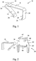
- Fig. 1 shows a clamping spring 10 according to the invention according to a preferred embodiment.
- the clamping spring 10 has a clamping leg 12, a bearing leg 14 and a bending joint 16, wherein the clamping leg 12 are connected to the bearing leg 14 via the bending joint 16 with each other.
- the clamping leg 12, the bearing leg 14 and the bending joint 16 are made of a spring steel strip, wherein the spring steel strip in the region of the bending joint 16 has a greater width than in the region of the clamping leg 12 and the bearing leg 14.
- the spring steel strip preferably forms at its one edge portion 18th a flush flat surface between clamping legs, Biegegesch and bearing legs.
- edge region 20 of the spring steel strip protrudes in the region of the bending joint 16 with respect to the edge region in the region of the clamping leg 12 and of the bearing leg 14, as in FIG Fig. 1 is clearly visible.
- the bending leg 12 connecting the clamping leg 12 and the bearing leg 14 has a rounding with the smallest possible bending radius, so that the clamping spring 10 has the smallest possible construction.
- the clamping space 22 is formed by the clamping leg 12, the bearing leg 14, the bending joint 16 and an opposite to the bending joint 16 end of the bearing leg 14 limiting leg 24.
- the limiting leg 24 is preferably arranged at a 90 ° angle to the bearing leg 14 on the bearing leg 14 and is also formed from the spring steel strip and preferably has the same width as the bearing leg 14.
- the limiting leg 24 is not out of its desired position by applying a Pressure, for example by means of a conductor to be clamped, can be pushed away, the limiting leg 24 has a nose element 26 for fixing the limiting leg 24 in the desired position.
- the nose member 26 is preferably disposed on an edge portion 28 of the limiting leg 24, which upon insertion of the clamping spring 10 in a, as in Fig. 2 shown receiving element 30, is applied to the receiving element 30, wherein the nose element 26 is preferably arranged at the end of the limiting leg 24, which does not adjoin the bearing leg 14.
- the nose element 26 is preferably positionable in an opening 32 of a receiving element 30 surrounding the clamping spring 10.
- the clamping leg 12 preferably has at its opposite end of the bending joint 16 to the clamping leg 12 opposite beveled portion 34, whereby the most optimal clamping angle between the clamping leg 12 of the clamping spring 10 and the clamped conductor can be achieved.
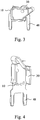
- FIG. 2 is a preferred embodiment of a receiving element 30 according to the invention for receiving a, as in Fig. 1 shown clamping spring 10, shown.
- the receiving element 30 is made of a current-conducting material and is substantially U-shaped, with a flat plate 36 having two opposing tabs 38, 40, which are preferably arranged at a 90 ° angle to the flat plate 36.
- the clamping spring 10 is fixed in the U-shape of the receiving element 30 between the two tabs 38, 40, wherein the bearing leg 14 of the clamping spring 10 is positioned adjacent to the tab 38 of the receiving element 30.
- the receiving element 30 has in the region of its flat plate an opening 32 in which the nose element 26 of the limiting leg 24 of the clamping spring 10 can be inserted, so that the limiting leg 24 can not be pushed away from its desired position.
- a recess 44 is provided, through which the insertion depth of a, not shown, tool is limited in the terminal space 22 of the clamping spring 10.
- the recess 44 serves as a stop, whereby it can be prevented that the tool is inserted too far into the receiving element 30, which would otherwise lead to overstretching of the clamping leg 12.
- the recess 44 is configured such that the clamping spring 10 abuts against the recess 44 in the region of the wider bending joint 16 with a sufficiently large deflection of the clamping leg 12 during insertion of a tool with the bending joint 16 and thereby prevents further insertion of the tool.
- the receiving element 30 also has a bulge 46 in the region of its flat plate 36.
- the bulge 46 preferably projects into the clamping space 22 of the clamping spring 10. If the clamping leg 12 is pressed into the clamping space 22 due to the introduction of a tool, then the clamping leg 12 can only be deflected to the extent that it abuts against the bulge 46. By means of the bulge 46 can be prevented overstretching of the clamping leg 12 due to excessive deflection.
- a latch 47 for fixing the receiving element 30 in a, as in Fig. 9 shown housing.
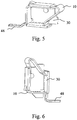
- FIG. 3, 4 . 5 and 6 the receiving element 30 is shown together with the clamping spring 10 in an assembled state, wherein on the basis of FIGS. 3, 4 . 5 and 6 the large variance of the receiving element 30 according to the invention with respect to the soldering of the receiving element 30 can be seen.
- solder pins 48 arranged on the receiving element 30 different forms of soldering, such as horizontal, vertical through-hole and SMD, and plug systems, standard and inverted can be implemented, the actual clamping region of the receiving element 30, in which the clamping spring 10 can be arranged, preferably always remains the same.
- the bending joint 16 is also preferably the material thickness of the receiving element 30 set up so that the upper edge of the tab 38 is flush with the upper edge of the flexure 16 at a height as in FIG Fig. 3 is clearly visible.
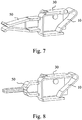
- FIGS. 7 and 8 show a further embodiment of a receiving element 30 and a clamping spring 10, wherein the limiting leg 24 is secured by means of a limiting element 50 against pushing away.
- the delimiting element 50 is preferably arranged on the side face of the limiting limb 24 facing away from the clamping space 22 and may be designed, for example, in the form of a U-shaped angled limb, so that a uniform counterpressure force can be exerted on the limiter limb 24 by means of the limbs.
- Such a limiting element 50 may be provided in addition to the nose element 26 or else alone without the nose element 26.
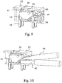
- Fig. 9 shows an embodiment of the invention, in which the receiving element 30 is arranged in a housing 52.
- the housing 52 has a receiving opening 54 for, as in Fig. 10 shown tool 56 and a Portereintechnologyö réelle 58.
- the receiving opening 54 for the tool 56 has a wall element 60, which is designed such that it can serve as a stop element for a arranged in the receiving element 30 clamping spring 10 and that it can fix the recorded in the receiving opening 54 tool 56.
- the receiving opening 54 of the housing 52 may, as in Fig.
- a tool 56 preferably a screwdriver
- a tool 56 are introduced in the direction of the receiving element 30 to open the arranged in the receiving element 30 clamping spring 10 by a deflection of the clamping leg 12 of the clamping spring 10, so that an inserted over the Leiterein Concreteö réelle 58 conductor 62 in the Clamping spring 10 can be clamped or an already clamped conductor 62 can be solved.
- the wall member 60 surrounding the opening of the receiving opening 54 may guide the tool 56 in its movement.
- the wall element 60 preferably adjoins at least partially against the clamping spring 10 arranged in the receiving element 30, preferably in the region of the bending joint 16 and / or the clamping leg 12 and thus serves as a stop element for the clamping spring 10, since the freedom of movement of the clamping spring 10 in this area the Wall element 60 of the housing 52 is limited. Furthermore, the wall element 60 is preferably shaped such that, in coordination with the receiving element 30 and the clamping spring 10, it can clamp the tool 56 to be opened to open the clamping space 22 so that the operator does not hold the tool 56 for insertion or connection of the conductor 62 must, but has both hands free. This greatly facilitates the operation of the spring clamp for an operator.
- the conductor insertion opening 58 is preferably funnel-shaped.
- Theauereintechnologyöong 58 serves as a stop for the receiving element 30 and on the other as limiting a deflection movement of the clamping leg 12 of the receiving element 30 arranged in the clamping spring 10, theauereintechnologyöong 58 is preferably disposed in the region of the folded portion 34 of the clamping leg 12.
- the housing 52 has a recess 64, in which a arranged on the receiving element 30 locking lug 47 for fixing the receiving element 30 to the housing 52 can be fastened.
Landscapes
- Clamps And Clips (AREA)
- Connections Arranged To Contact A Plurality Of Conductors (AREA)
- Details Of Connecting Devices For Male And Female Coupling (AREA)
Priority Applications (1)
| Application Number | Priority Date | Filing Date | Title |
|---|---|---|---|
| PL10704308T PL2377203T3 (pl) | 2009-01-09 | 2010-01-07 | Sprężyna zaciskowa do zacisku sprężynowego |
Applications Claiming Priority (2)
| Application Number | Priority Date | Filing Date | Title |
|---|---|---|---|
| DE102009004513A DE102009004513A1 (de) | 2009-01-09 | 2009-01-09 | Klemmfeder für eine Federkraftklemme |
| PCT/EP2010/000039 WO2010079130A1 (de) | 2009-01-09 | 2010-01-07 | Klemmfeder für eine federkraftklemme |
Publications (2)
| Publication Number | Publication Date |
|---|---|
| EP2377203A1 EP2377203A1 (de) | 2011-10-19 |
| EP2377203B1 true EP2377203B1 (de) | 2017-08-16 |
Family
ID=42173079
Family Applications (1)
| Application Number | Title | Priority Date | Filing Date |
|---|---|---|---|
| EP10704308.5A Active EP2377203B1 (de) | 2009-01-09 | 2010-01-07 | Klemmfeder für eine federkraftklemme |
Country Status (9)
| Country | Link |
|---|---|
| US (1) | US8485841B2 (cg-RX-API-DMAC7.html) |
| EP (1) | EP2377203B1 (cg-RX-API-DMAC7.html) |
| JP (1) | JP2012514840A (cg-RX-API-DMAC7.html) |
| CN (2) | CN105720389B (cg-RX-API-DMAC7.html) |
| DE (1) | DE102009004513A1 (cg-RX-API-DMAC7.html) |
| DK (1) | DK2377203T3 (cg-RX-API-DMAC7.html) |
| PL (1) | PL2377203T3 (cg-RX-API-DMAC7.html) |
| PT (1) | PT2377203T (cg-RX-API-DMAC7.html) |
| WO (1) | WO2010079130A1 (cg-RX-API-DMAC7.html) |
Families Citing this family (43)
| Publication number | Priority date | Publication date | Assignee | Title |
|---|---|---|---|---|
| CN107069274B (zh) * | 2010-05-07 | 2020-08-18 | 安费诺有限公司 | 高性能线缆连接器 |
| DE202010009666U1 (de) * | 2010-06-30 | 2011-11-29 | Weidmüller Interface GmbH & Co. KG | Miniatur-Federklemme |
| DE202010008485U1 (de) * | 2010-09-08 | 2011-12-13 | Weidmüller Interface GmbH & Co. KG | Anschlussvorrichtung |
| DE202011005034U1 (de) * | 2011-04-08 | 2014-04-28 | Ptr Messtechnik Gmbh & Co. Kg | Leiterklemme für zwei gegenüberliegende Leiterplatten |
| DE202011050120U1 (de) * | 2011-05-13 | 2012-08-30 | Weidmüller Interface GmbH & Co. KG | Klemmeinheit und Anschlussvorrichtung mit einer solchen Klemmeinheit |
| USD704145S1 (en) * | 2011-07-13 | 2014-05-06 | Omron Corporation | Cable connection member for terminal block |
| USD704666S1 (en) * | 2011-07-13 | 2014-05-13 | Omron Corporation | Cable connection member for terminal block |
| DE202011110961U1 (de) * | 2011-08-15 | 2017-11-02 | Elringklinger Ag | Dichtung zum Abdichten eines Dichtspalts |
| JP5942367B2 (ja) | 2011-09-08 | 2016-06-29 | オムロン株式会社 | 導体接続器具およびこれを用いた中継ユニット |
| US20130196100A1 (en) * | 2012-01-26 | 2013-08-01 | Nike, Inc. | Three-Dimensional Bag With Affixed Seams |
| US8882533B2 (en) | 2012-05-25 | 2014-11-11 | Tyco Electronics Corporation | Electrical connector having poke-in wire contact |
| AT13582U1 (de) * | 2012-07-27 | 2014-04-15 | Tridonic Connection Technology Gmbh & Co Kg | Anschluss- oder Verbindungsklemme, sowie Leiterplatte und Leuchte |
| DE202013100635U1 (de) | 2013-02-13 | 2013-03-04 | Wago Verwaltungsgesellschaft Mbh | Federklemmkontakt und Verbindungsklemme für elektrische Leiter |
| DE202013105944U1 (de) | 2013-12-26 | 2014-01-22 | Wago Verwaltungsgesellschaft Mbh | Federkraft-Klemmanschluss und Steckverbinder hiermit |
| EP3108542B1 (en) | 2014-02-17 | 2019-04-03 | Wuerth Elektronik Stelvio Kontek S.p.A. | Improved electrical connector |
| US9419352B2 (en) * | 2014-07-23 | 2016-08-16 | GE Lighting Solutions, LLC | Terminal block with ground strap, spring force terminals, and screw lug terminal |
| CN104241886B (zh) * | 2014-08-15 | 2016-05-25 | 南京大全电气有限公司 | 铜排导线连接器 |
| TWI544705B (zh) | 2014-09-05 | 2016-08-01 | 町洋企業股份有限公司 | 蝶形彈簧連接器 |
| JP6572697B2 (ja) | 2015-09-15 | 2019-09-11 | オムロン株式会社 | ソケット |
| JP6531585B2 (ja) | 2015-09-15 | 2019-06-19 | オムロン株式会社 | ソケット |
| DE202015105023U1 (de) * | 2015-09-22 | 2016-12-23 | Weidmüller Interface GmbH & Co. KG | Anschlussvorrichtung für Leiter |
| DE202015105022U1 (de) * | 2015-09-22 | 2016-12-23 | Weidmüller Interface GmbH & Co. KG | Anschlussvorrichtung für Leiter |
| DE102015119484A1 (de) | 2015-11-11 | 2017-05-11 | Phoenix Contact Gmbh & Co. Kg | Steckkontakt |
| EP3206260A1 (fr) | 2016-02-15 | 2017-08-16 | ABB Schweiz AG | Appareil électrique ayant une borne de connexion à pression avec une agrafe de support guidant et limitant la déformation élastique du ressort de contact |
| EP3206259B1 (fr) * | 2016-02-15 | 2020-12-30 | ABB Schweiz AG | Contacteur électrique avec une borne de connexion à pression montée dans un boitier à deux parties assemblées suivant la direction d'insertion d'un conducteur électrique dans la borne de connexion |
| WO2017166083A1 (zh) * | 2016-03-30 | 2017-10-05 | 潘昌雄 | 电连接器 |
| LU93039B1 (de) * | 2016-04-22 | 2017-10-27 | Phoenix Contact Gmbh & Co Kg Intellectual Property Licenses & Standards | Steckkontakt |
| DE102016107482A1 (de) * | 2016-04-22 | 2017-10-26 | Phoenix Contact Gmbh & Co. Kg | Steckkontakt |
| CN107528137B (zh) * | 2016-06-20 | 2025-03-04 | 进联电子科技(上海)有限公司 | 导线联接端子的接电头限制器改良结构 |
| DE102016111626B4 (de) | 2016-06-24 | 2018-01-18 | Wago Verwaltungsgesellschaft Mbh | Leiteranschlussklemme |
| DE102016111627A1 (de) | 2016-06-24 | 2017-12-28 | Wago Verwaltungsgesellschaft Mbh | Leiteranschlussklemme |
| JP2018107079A (ja) * | 2016-12-28 | 2018-07-05 | オムロン株式会社 | 端子台 |
| USD862632S1 (en) * | 2017-01-03 | 2019-10-08 | Leupold & Stevens, Inc. | Throw lever for an optical aiming device |
| TWM550924U (zh) * | 2017-05-26 | 2017-10-21 | Switchlab Inc | 用於電聯接端子之金屬彈片結構 |
| TWM553505U (zh) * | 2017-05-26 | 2017-12-21 | Switchlab Inc | 用於電聯接端子之金屬彈片改良結構 |
| TWM550925U (zh) * | 2017-05-26 | 2017-10-21 | Switchlab Inc | 用於電聯接端子之金屬彈片保護結構 |
| TWI691132B (zh) * | 2017-07-06 | 2020-04-11 | 進聯工業股份有限公司 | 導線聯接端子之導電組件結構 |
| US10559897B1 (en) | 2018-09-07 | 2020-02-11 | Lear Corporation | Push-in electrical terminal with insulation contact |
| US10367271B1 (en) * | 2018-11-20 | 2019-07-30 | Dinkle Enterprise Co., Ltd. | Terminal block with lateral elastic handles |
| JP7006575B2 (ja) * | 2018-12-11 | 2022-01-24 | オムロン株式会社 | 端子モジュールおよび端子台 |
| DE102020121004A1 (de) * | 2019-08-15 | 2021-02-18 | Phoenix Contact Gmbh & Co. Kg | Kontaktelement und Anschlusselement |
| DE202020102539U1 (de) * | 2020-05-06 | 2021-09-16 | WAGO Verwaltungsgesellschaft mit beschränkter Haftung | Leiteranschlussklemme |
| DE102022132682A1 (de) * | 2022-12-08 | 2024-06-13 | WAGO Verwaltungsgesellschaft mit beschränkter Haftung | Leiteranschlussmodul |
Citations (1)
| Publication number | Priority date | Publication date | Assignee | Title |
|---|---|---|---|---|
| DE102006005260A1 (de) * | 2006-02-02 | 2007-08-16 | Phoenix Contact Gmbh & Co. Kg | Elektrische Anschlußklemme |
Family Cites Families (23)
| Publication number | Priority date | Publication date | Assignee | Title |
|---|---|---|---|---|
| US2713668A (en) * | 1951-06-21 | 1955-07-19 | Hart Mfg Co | Quick detachable electrical connector |
| DE2440825A1 (de) * | 1974-08-26 | 1976-03-18 | Tony Adels Elektro U Waermetec | Elektrische anschlussklemme mit klemmfeder |
| JPH0241367U (cg-RX-API-DMAC7.html) * | 1988-06-17 | 1990-03-22 | ||
| JPH0747805Y2 (ja) * | 1989-03-17 | 1995-11-01 | 株式会社新光製作所 | プリント配線基板用端子装置 |
| JPH0755821Y2 (ja) * | 1989-10-24 | 1995-12-20 | 株式会社新光製作所 | 鎖錠端子 |
| JP3146048B2 (ja) * | 1991-12-27 | 2001-03-12 | 株式会社日辰電機製作所 | 電線接続装置 |
| EP0616386A3 (en) * | 1993-03-18 | 1996-03-13 | Tadao Tozuka | Plug-in connector. |
| JPH0955238A (ja) * | 1995-08-10 | 1997-02-25 | Shinko Seisakusho:Kk | 端子装置 |
| US6062918A (en) * | 1996-07-01 | 2000-05-16 | The Whitaker Corporation | Electrical receptacle contact assembly |
| DE29920231U1 (de) | 1999-11-17 | 2001-04-05 | Weidmüller Interface GmbH & Co, 32760 Detmold | Schraubenlose Anschlußklemme |
| JP2001307789A (ja) * | 2000-04-18 | 2001-11-02 | Hakko Denki Seisakusho:Kk | 電気コネクタ |
| KR100480196B1 (ko) * | 2000-08-04 | 2005-04-06 | 오므론 가부시키가이샤 | 전선 접속기구 |
| JP2002260764A (ja) * | 2001-03-02 | 2002-09-13 | Jimbo Electric Co Ltd | 情報用コンセント |
| JP2003346936A (ja) * | 2002-05-28 | 2003-12-05 | Toyo Giken Kk | 端子台 |
| DE20312861U1 (de) * | 2003-08-20 | 2003-10-30 | Phoenix Contact GmbH & Co. KG, 32825 Blomberg | Federkraftklemme |
| DE102004045025B3 (de) * | 2004-09-15 | 2006-02-16 | Phoenix Contact Gmbh & Co. Kg | Elektrische Anschluß- oder Verbindungsklemme |
| DE102004059017B4 (de) * | 2004-12-08 | 2006-12-14 | Phoenix Contact Gmbh & Co. Kg | Kastenfederklemme mit einem an einer ersten Kastenwand angeordneten Klemmschenkel |
| DE102005014075B3 (de) | 2005-03-23 | 2006-10-26 | Phoenix Contact Gmbh & Co. Kg | Federkraftklemme mit wenigstens einer in einem Gehäuse angeordneten Klemmfeder |
| DE102005048972B4 (de) * | 2005-10-13 | 2010-08-12 | Phoenix Contact Gmbh & Co. Kg | Federkraftklemme mit Klemmfeder und Strombalken |
| DE202006009460U1 (de) * | 2005-10-29 | 2007-03-15 | Weidmüller Interface GmbH & Co. KG | Anschlussvorrichtung für Leiter |
| DE102006014646B4 (de) * | 2006-03-28 | 2008-06-26 | Phoenix Contact Gmbh & Co. Kg | Anschlussklemme für Leiterplatten |
| DE102007022806B3 (de) * | 2007-05-11 | 2008-11-27 | Wago Verwaltungsgesellschaft Mbh | Klemmenbauteil |
| CN201072809Y (zh) * | 2007-08-15 | 2008-06-11 | 卢朝栏 | 改良的承结装置 |
-
2009
- 2009-01-09 DE DE102009004513A patent/DE102009004513A1/de not_active Withdrawn
-
2010
- 2010-01-07 CN CN201610053231.8A patent/CN105720389B/zh active Active
- 2010-01-07 US US13/142,882 patent/US8485841B2/en not_active Expired - Fee Related
- 2010-01-07 PL PL10704308T patent/PL2377203T3/pl unknown
- 2010-01-07 JP JP2011544841A patent/JP2012514840A/ja active Pending
- 2010-01-07 WO PCT/EP2010/000039 patent/WO2010079130A1/de not_active Ceased
- 2010-01-07 DK DK10704308.5T patent/DK2377203T3/en active
- 2010-01-07 CN CN201080004345.4A patent/CN102273014B/zh active Active
- 2010-01-07 EP EP10704308.5A patent/EP2377203B1/de active Active
- 2010-01-07 PT PT107043085T patent/PT2377203T/pt unknown
Patent Citations (1)
| Publication number | Priority date | Publication date | Assignee | Title |
|---|---|---|---|---|
| DE102006005260A1 (de) * | 2006-02-02 | 2007-08-16 | Phoenix Contact Gmbh & Co. Kg | Elektrische Anschlußklemme |
Also Published As
| Publication number | Publication date |
|---|---|
| JP2012514840A (ja) | 2012-06-28 |
| CN102273014B (zh) | 2016-03-02 |
| PL2377203T3 (pl) | 2017-12-29 |
| CN105720389B (zh) | 2018-11-23 |
| DE102009004513A1 (de) | 2010-07-22 |
| WO2010079130A1 (de) | 2010-07-15 |
| CN102273014A (zh) | 2011-12-07 |
| US20110312228A1 (en) | 2011-12-22 |
| DK2377203T3 (en) | 2017-10-23 |
| EP2377203A1 (de) | 2011-10-19 |
| US8485841B2 (en) | 2013-07-16 |
| CN105720389A (zh) | 2016-06-29 |
| PT2377203T (pt) | 2017-10-03 |
Similar Documents
| Publication | Publication Date | Title |
|---|---|---|
| WO2010079130A1 (de) | Klemmfeder für eine federkraftklemme | |
| EP1956684B1 (de) | Universalkontakt | |
| DE102007024690B4 (de) | Elektrische Anschluß- oder Verbindungsklemme | |
| EP3446366B1 (de) | Steckkontakt | |
| EP2894718A2 (de) | Leiterplattenanschlussklemme | |
| DE202017101148U1 (de) | Leiteranschlusskontaktelement | |
| EP1085618A1 (de) | Steckverbindungssystem | |
| DE102016112831B4 (de) | Anschlussklemme | |
| DE102015119484A1 (de) | Steckkontakt | |
| DE3447135A1 (de) | Schraubenlose anschluss- und verbindungsklemme fuer elektrische leitungen | |
| DE102011009290B4 (de) | Anschlussklemme für Leiterplatten | |
| DE102010033112B4 (de) | Elektroinstallationsgerät | |
| DE10102453A1 (de) | Gehäuse zur Aufnahme eines steckbar mit dem Gehäuse verbindbaren Bauteils | |
| DE102015004160A1 (de) | Test-Contactor, Verfahren und Verwendung | |
| EP3309904A1 (de) | Gehäuse zum anschliessen wenigstens einer kabellitze eines kabels | |
| DE102017118818A1 (de) | Haltevorrichtung zur Befestigung von Kabelketten | |
| DE102015122400B4 (de) | Betätigungswerkzeug und Set aus isolierstoffgehäusefreier Leiterplattenklemme und Betätigungswerkzeug sowie Verwendung und Verfahren | |
| CH678776A5 (en) | Supplementary terminal for large flat or round cables - clips cable under existing screw head with contact pressure maintained by leaf spring between two portions | |
| DE102021109581A1 (de) | Kontaktfederanordnung mit Löseorgan | |
| EP1243078B1 (de) | Elektrisches gerät mit einem gehäuse | |
| DE10227235A1 (de) | Leiteranschluss | |
| DE10340332B3 (de) | Elektrischer Steckkontakt | |
| DE102008016076A1 (de) | Verbinderschirmung, Verbindersystem und Verwendung | |
| DE19610610A1 (de) | Anordnung zur Verbindung eines elektrischen Leiters mit einem Schneidklemmkontakt | |
| WO2013091846A1 (de) | Anschlussklemme |
Legal Events
| Date | Code | Title | Description |
|---|---|---|---|
| PUAI | Public reference made under article 153(3) epc to a published international application that has entered the european phase |
Free format text: ORIGINAL CODE: 0009012 |
|
| 17P | Request for examination filed |
Effective date: 20110702 |
|
| AK | Designated contracting states |
Kind code of ref document: A1 Designated state(s): AT BE BG CH CY CZ DE DK EE ES FI FR GB GR HR HU IE IS IT LI LT LU LV MC MK MT NL NO PL PT RO SE SI SK SM TR |
|
| DAX | Request for extension of the european patent (deleted) | ||
| 17Q | First examination report despatched |
Effective date: 20140321 |
|
| GRAP | Despatch of communication of intention to grant a patent |
Free format text: ORIGINAL CODE: EPIDOSNIGR1 |
|
| STAA | Information on the status of an ep patent application or granted ep patent |
Free format text: STATUS: GRANT OF PATENT IS INTENDED |
|
| INTG | Intention to grant announced |
Effective date: 20170421 |
|
| GRAS | Grant fee paid |
Free format text: ORIGINAL CODE: EPIDOSNIGR3 |
|
| GRAA | (expected) grant |
Free format text: ORIGINAL CODE: 0009210 |
|
| STAA | Information on the status of an ep patent application or granted ep patent |
Free format text: STATUS: THE PATENT HAS BEEN GRANTED |
|
| AK | Designated contracting states |
Kind code of ref document: B1 Designated state(s): AT BE BG CH CY CZ DE DK EE ES FI FR GB GR HR HU IE IS IT LI LT LU LV MC MK MT NL NO PL PT RO SE SI SK SM TR |
|
| REG | Reference to a national code |
Ref country code: GB Ref legal event code: FG4D Free format text: NOT ENGLISH |
|
| REG | Reference to a national code |
Ref country code: CH Ref legal event code: EP |
|
| REG | Reference to a national code |
Ref country code: IE Ref legal event code: FG4D Free format text: LANGUAGE OF EP DOCUMENT: GERMAN |
|
| REG | Reference to a national code |
Ref country code: AT Ref legal event code: REF Ref document number: 919921 Country of ref document: AT Kind code of ref document: T Effective date: 20170915 |
|
| REG | Reference to a national code |
Ref country code: DE Ref legal event code: R096 Ref document number: 502010014018 Country of ref document: DE |
|
| REG | Reference to a national code |
Ref country code: PT Ref legal event code: SC4A Ref document number: 2377203 Country of ref document: PT Date of ref document: 20171003 Kind code of ref document: T Free format text: AVAILABILITY OF NATIONAL TRANSLATION Effective date: 20170922 |
|
| REG | Reference to a national code |
Ref country code: DK Ref legal event code: T3 Effective date: 20171018 |
|
| REG | Reference to a national code |
Ref country code: SE Ref legal event code: TRGR |
|
| REG | Reference to a national code |
Ref country code: NL Ref legal event code: MP Effective date: 20170816 |
|
| REG | Reference to a national code |
Ref country code: LT Ref legal event code: MG4D |
|
| PG25 | Lapsed in a contracting state [announced via postgrant information from national office to epo] |
Ref country code: NL Free format text: LAPSE BECAUSE OF FAILURE TO SUBMIT A TRANSLATION OF THE DESCRIPTION OR TO PAY THE FEE WITHIN THE PRESCRIBED TIME-LIMIT Effective date: 20170816 Ref country code: LT Free format text: LAPSE BECAUSE OF FAILURE TO SUBMIT A TRANSLATION OF THE DESCRIPTION OR TO PAY THE FEE WITHIN THE PRESCRIBED TIME-LIMIT Effective date: 20170816 Ref country code: NO Free format text: LAPSE BECAUSE OF FAILURE TO SUBMIT A TRANSLATION OF THE DESCRIPTION OR TO PAY THE FEE WITHIN THE PRESCRIBED TIME-LIMIT Effective date: 20171116 Ref country code: FI Free format text: LAPSE BECAUSE OF FAILURE TO SUBMIT A TRANSLATION OF THE DESCRIPTION OR TO PAY THE FEE WITHIN THE PRESCRIBED TIME-LIMIT Effective date: 20170816 |
|
| PG25 | Lapsed in a contracting state [announced via postgrant information from national office to epo] |
Ref country code: BG Free format text: LAPSE BECAUSE OF FAILURE TO SUBMIT A TRANSLATION OF THE DESCRIPTION OR TO PAY THE FEE WITHIN THE PRESCRIBED TIME-LIMIT Effective date: 20171116 Ref country code: ES Free format text: LAPSE BECAUSE OF FAILURE TO SUBMIT A TRANSLATION OF THE DESCRIPTION OR TO PAY THE FEE WITHIN THE PRESCRIBED TIME-LIMIT Effective date: 20170816 Ref country code: LV Free format text: LAPSE BECAUSE OF FAILURE TO SUBMIT A TRANSLATION OF THE DESCRIPTION OR TO PAY THE FEE WITHIN THE PRESCRIBED TIME-LIMIT Effective date: 20170816 Ref country code: IS Free format text: LAPSE BECAUSE OF FAILURE TO SUBMIT A TRANSLATION OF THE DESCRIPTION OR TO PAY THE FEE WITHIN THE PRESCRIBED TIME-LIMIT Effective date: 20171216 Ref country code: GR Free format text: LAPSE BECAUSE OF FAILURE TO SUBMIT A TRANSLATION OF THE DESCRIPTION OR TO PAY THE FEE WITHIN THE PRESCRIBED TIME-LIMIT Effective date: 20171117 |
|
| PGFP | Annual fee paid to national office [announced via postgrant information from national office to epo] |
Ref country code: PT Payment date: 20171227 Year of fee payment: 9 |
|
| PG25 | Lapsed in a contracting state [announced via postgrant information from national office to epo] |
Ref country code: RO Free format text: LAPSE BECAUSE OF FAILURE TO SUBMIT A TRANSLATION OF THE DESCRIPTION OR TO PAY THE FEE WITHIN THE PRESCRIBED TIME-LIMIT Effective date: 20170816 Ref country code: CZ Free format text: LAPSE BECAUSE OF FAILURE TO SUBMIT A TRANSLATION OF THE DESCRIPTION OR TO PAY THE FEE WITHIN THE PRESCRIBED TIME-LIMIT Effective date: 20170816 |
|
| REG | Reference to a national code |
Ref country code: DE Ref legal event code: R097 Ref document number: 502010014018 Country of ref document: DE |
|
| PG25 | Lapsed in a contracting state [announced via postgrant information from national office to epo] |
Ref country code: EE Free format text: LAPSE BECAUSE OF FAILURE TO SUBMIT A TRANSLATION OF THE DESCRIPTION OR TO PAY THE FEE WITHIN THE PRESCRIBED TIME-LIMIT Effective date: 20170816 Ref country code: SK Free format text: LAPSE BECAUSE OF FAILURE TO SUBMIT A TRANSLATION OF THE DESCRIPTION OR TO PAY THE FEE WITHIN THE PRESCRIBED TIME-LIMIT Effective date: 20170816 Ref country code: SM Free format text: LAPSE BECAUSE OF FAILURE TO SUBMIT A TRANSLATION OF THE DESCRIPTION OR TO PAY THE FEE WITHIN THE PRESCRIBED TIME-LIMIT Effective date: 20170816 |
|
| PGFP | Annual fee paid to national office [announced via postgrant information from national office to epo] |
Ref country code: SE Payment date: 20180129 Year of fee payment: 9 |
|
| PLBE | No opposition filed within time limit |
Free format text: ORIGINAL CODE: 0009261 |
|
| STAA | Information on the status of an ep patent application or granted ep patent |
Free format text: STATUS: NO OPPOSITION FILED WITHIN TIME LIMIT |
|
| 26N | No opposition filed |
Effective date: 20180517 |
|
| PG25 | Lapsed in a contracting state [announced via postgrant information from national office to epo] |
Ref country code: SI Free format text: LAPSE BECAUSE OF FAILURE TO SUBMIT A TRANSLATION OF THE DESCRIPTION OR TO PAY THE FEE WITHIN THE PRESCRIBED TIME-LIMIT Effective date: 20170816 |
|
| REG | Reference to a national code |
Ref country code: CH Ref legal event code: PL |
|
| GBPC | Gb: european patent ceased through non-payment of renewal fee |
Effective date: 20180107 |
|
| PG25 | Lapsed in a contracting state [announced via postgrant information from national office to epo] |
Ref country code: MT Free format text: LAPSE BECAUSE OF FAILURE TO SUBMIT A TRANSLATION OF THE DESCRIPTION OR TO PAY THE FEE WITHIN THE PRESCRIBED TIME-LIMIT Effective date: 20170816 |
|
| PG25 | Lapsed in a contracting state [announced via postgrant information from national office to epo] |
Ref country code: FR Free format text: LAPSE BECAUSE OF NON-PAYMENT OF DUE FEES Effective date: 20180131 Ref country code: LU Free format text: LAPSE BECAUSE OF NON-PAYMENT OF DUE FEES Effective date: 20180107 |
|
| REG | Reference to a national code |
Ref country code: IE Ref legal event code: MM4A |
|
| REG | Reference to a national code |
Ref country code: FR Ref legal event code: ST Effective date: 20180928 |
|
| REG | Reference to a national code |
Ref country code: BE Ref legal event code: MM Effective date: 20180131 |
|
| PG25 | Lapsed in a contracting state [announced via postgrant information from national office to epo] |
Ref country code: CH Free format text: LAPSE BECAUSE OF NON-PAYMENT OF DUE FEES Effective date: 20180131 Ref country code: GB Free format text: LAPSE BECAUSE OF NON-PAYMENT OF DUE FEES Effective date: 20180107 Ref country code: BE Free format text: LAPSE BECAUSE OF NON-PAYMENT OF DUE FEES Effective date: 20180131 Ref country code: LI Free format text: LAPSE BECAUSE OF NON-PAYMENT OF DUE FEES Effective date: 20180131 |
|
| PG25 | Lapsed in a contracting state [announced via postgrant information from national office to epo] |
Ref country code: IE Free format text: LAPSE BECAUSE OF NON-PAYMENT OF DUE FEES Effective date: 20180107 |
|
| PGFP | Annual fee paid to national office [announced via postgrant information from national office to epo] |
Ref country code: PL Payment date: 20180102 Year of fee payment: 9 |
|
| REG | Reference to a national code |
Ref country code: AT Ref legal event code: MM01 Ref document number: 919921 Country of ref document: AT Kind code of ref document: T Effective date: 20180107 |
|
| PG25 | Lapsed in a contracting state [announced via postgrant information from national office to epo] |
Ref country code: AT Free format text: LAPSE BECAUSE OF NON-PAYMENT OF DUE FEES Effective date: 20180107 |
|
| PG25 | Lapsed in a contracting state [announced via postgrant information from national office to epo] |
Ref country code: MC Free format text: LAPSE BECAUSE OF FAILURE TO SUBMIT A TRANSLATION OF THE DESCRIPTION OR TO PAY THE FEE WITHIN THE PRESCRIBED TIME-LIMIT Effective date: 20170816 |
|
| PG25 | Lapsed in a contracting state [announced via postgrant information from national office to epo] |
Ref country code: SE Free format text: LAPSE BECAUSE OF NON-PAYMENT OF DUE FEES Effective date: 20190108 Ref country code: PT Free format text: LAPSE BECAUSE OF NON-PAYMENT OF DUE FEES Effective date: 20190708 |
|
| PG25 | Lapsed in a contracting state [announced via postgrant information from national office to epo] |
Ref country code: TR Free format text: LAPSE BECAUSE OF FAILURE TO SUBMIT A TRANSLATION OF THE DESCRIPTION OR TO PAY THE FEE WITHIN THE PRESCRIBED TIME-LIMIT Effective date: 20170816 |
|
| PG25 | Lapsed in a contracting state [announced via postgrant information from national office to epo] |
Ref country code: HU Free format text: LAPSE BECAUSE OF FAILURE TO SUBMIT A TRANSLATION OF THE DESCRIPTION OR TO PAY THE FEE WITHIN THE PRESCRIBED TIME-LIMIT; INVALID AB INITIO Effective date: 20100107 |
|
| PG25 | Lapsed in a contracting state [announced via postgrant information from national office to epo] |
Ref country code: CY Free format text: LAPSE BECAUSE OF FAILURE TO SUBMIT A TRANSLATION OF THE DESCRIPTION OR TO PAY THE FEE WITHIN THE PRESCRIBED TIME-LIMIT Effective date: 20170816 Ref country code: MK Free format text: LAPSE BECAUSE OF NON-PAYMENT OF DUE FEES Effective date: 20170816 Ref country code: HR Free format text: LAPSE BECAUSE OF FAILURE TO SUBMIT A TRANSLATION OF THE DESCRIPTION OR TO PAY THE FEE WITHIN THE PRESCRIBED TIME-LIMIT Effective date: 20170816 |
|
| PG25 | Lapsed in a contracting state [announced via postgrant information from national office to epo] |
Ref country code: PL Free format text: LAPSE BECAUSE OF NON-PAYMENT OF DUE FEES Effective date: 20190107 |
|
| PGFP | Annual fee paid to national office [announced via postgrant information from national office to epo] |
Ref country code: DK Payment date: 20230126 Year of fee payment: 14 |
|
| P01 | Opt-out of the competence of the unified patent court (upc) registered |
Effective date: 20230424 |
|
| PGFP | Annual fee paid to national office [announced via postgrant information from national office to epo] |
Ref country code: IT Payment date: 20240123 Year of fee payment: 15 |
|
| REG | Reference to a national code |
Ref country code: DK Ref legal event code: EBP Effective date: 20240131 |
|
| PG25 | Lapsed in a contracting state [announced via postgrant information from national office to epo] |
Ref country code: DK Free format text: LAPSE BECAUSE OF NON-PAYMENT OF DUE FEES Effective date: 20240131 |
|
| PG25 | Lapsed in a contracting state [announced via postgrant information from national office to epo] |
Ref country code: DK Free format text: LAPSE BECAUSE OF NON-PAYMENT OF DUE FEES Effective date: 20240131 |
|
| PG25 | Lapsed in a contracting state [announced via postgrant information from national office to epo] |
Ref country code: IT Free format text: LAPSE BECAUSE OF NON-PAYMENT OF DUE FEES Effective date: 20250107 |
|
| PGFP | Annual fee paid to national office [announced via postgrant information from national office to epo] |
Ref country code: DE Payment date: 20260320 Year of fee payment: 17 |