EP2366863B1 - Coffre-tunnel incorporant une armature de renfort de sa structure - Google Patents
Coffre-tunnel incorporant une armature de renfort de sa structure Download PDFInfo
- Publication number
- EP2366863B1 EP2366863B1 EP11158790.3A EP11158790A EP2366863B1 EP 2366863 B1 EP2366863 B1 EP 2366863B1 EP 11158790 A EP11158790 A EP 11158790A EP 2366863 B1 EP2366863 B1 EP 2366863B1
- Authority
- EP
- European Patent Office
- Prior art keywords
- wall
- shutter box
- tunnel
- jamb
- walls
- Prior art date
- Legal status (The legal status is an assumption and is not a legal conclusion. Google has not performed a legal analysis and makes no representation as to the accuracy of the status listed.)
- Active
Links
- 230000003014 reinforcing effect Effects 0.000 title claims description 11
- 238000009415 formwork Methods 0.000 title 1
- 238000004519 manufacturing process Methods 0.000 claims description 11
- 238000004873 anchoring Methods 0.000 claims description 10
- 239000000463 material Substances 0.000 claims description 4
- 238000000465 moulding Methods 0.000 claims 1
- 238000010276 construction Methods 0.000 description 9
- 230000002787 reinforcement Effects 0.000 description 6
- 230000000694 effects Effects 0.000 description 4
- 239000011230 binding agent Substances 0.000 description 3
- 229910000831 Steel Inorganic materials 0.000 description 2
- 239000002131 composite material Substances 0.000 description 2
- 239000004794 expanded polystyrene Substances 0.000 description 2
- 238000012423 maintenance Methods 0.000 description 2
- 239000010959 steel Substances 0.000 description 2
- 239000011324 bead Substances 0.000 description 1
- 239000011248 coating agent Substances 0.000 description 1
- 238000000576 coating method Methods 0.000 description 1
- 230000000295 complement effect Effects 0.000 description 1
- 239000004567 concrete Substances 0.000 description 1
- 238000009434 installation Methods 0.000 description 1
- 239000011810 insulating material Substances 0.000 description 1
- 238000009413 insulation Methods 0.000 description 1
- 239000012212 insulator Substances 0.000 description 1
- 239000007788 liquid Substances 0.000 description 1
- 239000002184 metal Substances 0.000 description 1
- 239000004570 mortar (masonry) Substances 0.000 description 1
- 239000011505 plaster Substances 0.000 description 1
- 229920006327 polystyrene foam Polymers 0.000 description 1
- 230000001681 protective effect Effects 0.000 description 1
- 230000000284 resting effect Effects 0.000 description 1
- 238000005096 rolling process Methods 0.000 description 1
- 238000007789 sealing Methods 0.000 description 1
- 238000007711 solidification Methods 0.000 description 1
- 230000008023 solidification Effects 0.000 description 1
- 238000004804 winding Methods 0.000 description 1
Images


Classifications
-
- E—FIXED CONSTRUCTIONS
- E06—DOORS, WINDOWS, SHUTTERS, OR ROLLER BLINDS IN GENERAL; LADDERS
- E06B—FIXED OR MOVABLE CLOSURES FOR OPENINGS IN BUILDINGS, VEHICLES, FENCES OR LIKE ENCLOSURES IN GENERAL, e.g. DOORS, WINDOWS, BLINDS, GATES
- E06B9/00—Screening or protective devices for wall or similar openings, with or without operating or securing mechanisms; Closures of similar construction
- E06B9/02—Shutters, movable grilles, or other safety closing devices, e.g. against burglary
- E06B9/08—Roll-type closures
- E06B9/11—Roller shutters
- E06B9/17—Parts or details of roller shutters, e.g. suspension devices, shutter boxes, wicket doors, ventilation openings
- E06B9/17007—Shutter boxes; Details or component parts thereof
- E06B9/17015—Shutter boxes; Details or component parts thereof made of at most two pieces; Front opening details
Definitions
- the present invention relates to a tunnel box intended to be implanted at the top of a table receiving a frame of a window, a door.
- a tunnel box is intended to accommodate a roller shutter mechanism able to slide vis-à-vis the frame a blind apron window, the door.
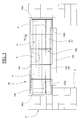
- a tunnel box usually comes up, as it appears on the Fig. 1 , in the form of a prismatic-looking CT part which is intended to be integrated into a masonry of a building under construction, above a table T delimiting the frame of a window or of a door.
- Such a tunnel trunk CT is often constituted by a molded envelope comprising a longitudinal recess E in the form of a tunnel opening into each of its ends and whose lower part is open to accommodate a shutter mechanism M held between two cheeks J1, J2 lateral closure of the recess, and which is shown schematically here by a center line.
- the envelope of the tunnel trunk CT is thus delimited by a wall of vault V and by two walls of jamb B, of which only one is visible on this Fig. 1 , and between which is formed the recess E.
- the tunnel box is delivered with its rolling shutter mechanism which is held via the two cheeks closing the lateral ends of the tunnel box. Heels extend, in principle, perpendicular to the cheeks in their lower part to serve as seating tunnel trunk when rests at its ends on the building elements. Each bead is held by its edges in two rails constituting two sections respectively overlapping the two legs on which it also bears on the masonry.
- the tunnel box is put in place at the top of the board, then secured, by pouring a binder such as mortar at the back of the cheeks and pouring a lintel on the top of the tunnel box. It can still be fixed under a lintel deposited above the table.
- a frame for an opening for example a door, a window, is fixed in the wall frame.
- This frame can be fixed off the wall by means of sealing tabs integral with the two side walls of the wall frame and the lower wall thereof.
- the thickness available between the wall and the frame is intended to receive insulation.
- the opening is fixed on the integral hinges of the frame.
- a tunnel box consisting of four walls assembled at right angles one after the other. Each wall is formed of an extruded profile.
- a bracket is fixed externally on the top wall to connect the tunnel box with a lintel.
- a U-shaped reinforcing plate made of steel, is fixed in the tunnel box, perpendicular to its walls to stiffen it. Its upper wing is extended by a lug which passes through the upper wall, and a hole in the part of the bracket in contact with said upper wall. The end of the pin is then folded.
- the applicant has sought a solution so that the tunnel box, which must withstand the horizontal forces transmitted by the connecting rail under the effect of the action of the wind on the opening, can withstand this effort by deforming as little as possible.
- tunnel box By reinforcing the structure of the tunnel box, the connection between the upper cross member of a frame capable of being fixed to the end of a jamb, for example by means of a connecting rail, is strengthened.
- tunnel box being specified that the tunnel box is intended to be secured to the upper part of a reception table of a frame of a window, a door. Thanks to this rigid connection, this upper crossbar and therefore the frame face the action of the wind by deforming well below acceptable standards.
- the structure of the tunnel box is homogeneously stiffened in transverse planes thereto. This solution is very effective because it can oppose the action of the wind whose direction is perpendicular to the window, the door.
- each arch comprises an intermediate branch disposed at the arch wall of the tunnel box, preferably extended respectively on both sides by two branches respectively disposed at the jamb walls.
- each arch comprises an intermediate branch disposed at the arch wall of the tunnel box, advantageously extended by one edge by a single branch disposed at a jamb wall.
- This arch is suitable for connecting a jamb wall, the one that supports the upper cross member of the frame, with the arch wall of the tunnel box.
- the tunnel box can be of the type with one or two walls of jamb.
- each arch includes an anchor tab to a lintel.
- This anchor reinforces the connection of the tunnel box with the lintel.
- This may be of the cast type in which case the anchor tab is embedded in it. It can also be of the reported type, in which case the anchor is fixed against him.
- a support wall of the anchor lug extends perpendicularly the intermediate branch in its upper part.
- the anchoring lug consists of a part having in side view an L-shaped geometry comprising a seat wall on the support wall, extended by a connecting wall to the lintel, the support wall and the seat wall being capable of being joined by a connecting means.
- the anchoring lug is secured to the hoop and the projecting portion of the anchor lug is secured to the lintel.
- the connecting means comprises notches and corresponding tenons.
- the anchoring tab is integrated in the structure of the arch.
- the hoop and the anchor are made of one and the same piece.
- the support wall is only partially connected to the intermediate branch, making it possible to fold the free portion of this support wall to form a connecting wall.
- the reinforcement comprises reinforcing rods arranged longitudinally in the arch wall and / or in the jamb walls of the tunnel box to reduce the strain under stress of these walls.
- the rods pass through holes provided in the branches of the rollbars so that forces applied on the jamb walls are uniformly distributed over the entire length of the tunnel box.
- the tunnel box 100 presented on the Fig. 3 , is intended to be integrated in a masonry of a building under construction, above a table T delimiting the installation frame of a window or a door. It is in the form of a part of prismatic appearance which is traversed longitudinally by a recess E intended to accommodate a roller shutter mechanism M comprising a winding drum O around which can be rolled, unwound an apron occultation of the window, of the door.
- the recess E thus opens into each of the ends of the tunnel box and also opens into its lower part over its entire length to accommodate the shutter mechanism and to intervene for maintenance, if necessary.
- the tunnel box 100 presented on the Figs. 2 and 3 , consists of a section delimited by a vault wall V, extended by two jamb walls B1 and B2 (visible distinctly on the Fig. 2 ) constituting the front face and the rear face of the tunnel box.
- the recess E is delimited between these walls.
- the profile is made of an insulating material from a thermal point of view. In an advantageous mode of manufacture, it is made of expanded polystyrene. It is preferably formed of a monolithic block, in one piece.
- each cheek consists of a closure wall of a lateral end and a flange arranged perpendicularly and whose geometry matches the outlet of the recess E through said lateral end.
- the shutter mechanism M is held between these two cheeks.
- two profiles 320 and 340 are respectively mounted on the free edges of the two legs B1 and B2. Their ends thus rest on the building elements thus protecting the jambs. Moreover, the presence of these two sections makes it possible to stiffen the free edges of the two legs whose thickness is relatively small.
- Each profile 320, 340 has a U-shaped section adapted to overlap the free edge of the corresponding leg.
- a groove 322, 342 longitudinally hollow the inner branch of each section to receive a side edge of a heel 300 for closing locally the recess E and more precisely the area of the recess located vertically above the building elements.
- the heel 300 is thus disposed in the extension of the lower part of each cheek being held laterally in the two profiles 320 and 340. It consists of an independent piece prismatic appearance or an extension of the cheek forming with she a monobloc piece.
- a connecting rail 400 overlaps the free edge of a jamb and here the leg B2 to connect the tunnel box to the upper rail TS of a frame D of door window.
- This arrangement allows, by linking these two components to limit the deformation of the frame under the action of the wind on the opening ov, held closed in the frame.
- the direction of the wind symbolized by the arrow F tends to bend the upper rail TS which is not normally anchored to the wall.
- the connecting rail 400 covers the section 340. This profile, which increases the stiffness of the leg, however, in an embodiment not shown, be absent. It is useful to remember that a wind speed exceeding 120 km / h can exert a differential pressure on a window, a door, which can reach 800 Pa.
- the connecting rail 400 consists of a section section U comprising an intermediate branch 410 extended by two lateral branches 420, 430.
- the distance separating the two lateral branches 420 and 430 is such that they are in contact with the inner and outer faces of the leg B2, when the connecting section overlaps said leg.
- the intermediate branch constitutes a support plate intended to be secured to the upper cross member TS of the frame D.
- This intermediate branch 410 extends below the side branches 420, 430, to provide significant rigidity to the connecting rail in a parallel plane at its intermediate branch, that is to say in the direction of the wind, in order to limit as much as possible the deformation of the upper crossbar TS.
- the height position of the connecting rail 400 on the free edge of the leg B2 can be adjusted so that the support plate 410 of the connecting rail 400 can be brought into contact with the upper face of the upper rail TS in order to to be solidarized.
- This support plate 410 is preferably fixed by screwing on the upper cross member TS.
- the support plate 410 is fixed by clipping in a retaining profile 440 secured to the upper cross member TS.
- This retaining profile 440 comprises a seat wall bordered laterally by two retaining clips of the support plate.
- the lateral branch of the connecting rail 400 intended to be turned towards the inside of the tunnel box, that is to say the branch 420, is provided with a slideway 422 provided for housing a side edge of a closing plate PF of the recess in its portion opening between the heels.
- This closure plate is commonly called soffit.
- the slideway 422 consists of two parallel ridges projecting perpendicularly from said branch 420.
- the connecting rail 400 is made of a material having a high rigidity such as steel or a composite material.
- an anchor tab 450 is fixed on one end of the connecting rail 400.
- the other end of the connecting rail is also provided with such an anchor tab 450.
- the anchoring lugs are intended to be sealed on the wall wall P to hold, by its ends, the connecting rail to increase its maintenance and thereby increase the rigidity of the frame with which it is associated.
- Each anchor tab presents on this Fig. 5 a Z-shaped cross section comprising a first fixing wall in the end of the connecting rail, a second intermediate wall and a third fixing wall on the wall wall.
- the support plate 410 of the connecting rail 400 is hollow so that it can receive a stiffening blade 412 to further improve its rigidity in a transverse plane.
- This connecting rail 400 and its accessories are elements of the state of the art which are useful for understanding invention.
- tunnel box 100 incorporates a frame 500 capable of increasing its rigidity in a transverse direction to reduce the deformation of the jamb wall which supports the connecting rail 400 relative to the complementary part of the tunnel box.
- This armature 500 comprises a plurality of arches 510 arranged regularly in the tunnel box and in transverse planes thereto. Each arch 510 is integrated inside the walls of vault V and jamb B1 and B2 which constitute the tunnel box.
- the hoop 510 presents on the Fig. 8 U-shaped geometry returned, comprising an intermediate branch 512, respectively extended on either side by two branches 514 and 516 arranged parallel to one another and oriented in the same direction.
- the intermediate branch 512 of the arch is intended to be placed at the level of the arch wall of the tunnel box while the branches 514 and 516 are intended to be placed at its jamb walls.
- the branches are also arranged in the same plane. Their thickness is almost constant. The width of these branches is greater than their thickness to give the arch a great
- the hoop is preferably made of metal or a composite material to give it a great stiffness compared to its footprint.
- the hoop is also preferably made in one piece to increase its rigidity.
- the arches are intended to be placed at regular intervals in the tunnel trunk manufacturing mold, so that they are integrated into its walls at the end of its manufacture. Passages 520 pass through the arch so that the molded material can pass through during the manufacture of the tunnel box and thus ensure a homogeneous structure to the tunnel box.
- the thickness of the vault wall V, jamb walls B1, B2 of the tunnel box is greater than the width of the branches of the arch.
- the hoop 510 may be secured to an anchor lug 530 with a lintel.
- a support wall 522 of the anchoring tab perpendicularly extends the intermediate branch 512 in its upper part. It is traversed by notches 524.
- the anchoring tab 530 consists of a part having in side view an L-shaped geometry comprising a wall 532 of seat on the support wall 522, extended by a connecting wall 534 with the lintel. Studs 536 are arranged under the seat wall 532 to cooperate by hooking with the notches 524 so that said anchoring tab can be made integral with the arch 510, as suggested by the arrow F1.
- the anchor lug 530 is secured to the lintel by pouring concrete the connecting wall 534 or by fixing this connecting wall on one face of the lintel. For this purpose, holes pass through said connecting wall.
- the hoop 510 presented with reference to the Fig. 8 and which has no support wall 522, illustrates the state of the art which is useful for understanding the invention.
- the anchoring tab 530 is integrated into the structure of the arch 510. Its support wall 522 is only partially connected to the intermediate branch 512, so that it is possible to fold the free part of this wall of support to form a connecting wall 534, as suggested by the arrow F2.
- the hoop 510 affects an inverted L-shaped geometry comprising an intermediate branch 512 connected to a single branch 514 intended to reinforce the jamb wall which supports the connecting rail.
- This connecting rail can then be secured to the lintel to further reduce the deformation of the frame under the effect of wind.
- This rail is suitable to be integrated in the construction of a tunnel box of the type comprising an arch wall and a single wall jamb.
- a lintel L was cast above the tunnel box 100 and the connecting wall 534 of the anchor tab 530 is embedded therein.
- a protective Ep coating is applied to the wall of the tunnel box which faces outwards. Plaster pl presented in the form of plates is still deposited against the inner wall of the wall P over an insulator Is and so as to mask the tunnel box 100.
- the reinforcement 500 of the tunnel box 100 further includes reinforcement rods 550 arranged longitudinally in the arch wall V and / or in the jamb walls B1, B2 to reduce the stress strain of these walls.
- the reinforcing rods 550 advantageously cross holes 552 provided in the branches of the hoops 510 so that forces applied to the jamb walls are uniformly distributed over the entire length of the tunnel box.
- the jamb walls B1, B2, then maintain their flatness.
- the trunk tunnel of the invention is advantageously used with a connecting rail adapted to overlap the free edge of a leg constituting it so that the connecting rail can be secured to the top rail of a frame to stiffen it. It can, however, be used without this connecting rail benefiting from the advantages of its rigid structure.
- the tunnel box of the invention has a reinforced structure compared to an earlier tunnel box.
- the tunnel box of the invention makes it possible to strengthen the connection of the upper cross member of the frame with the wall wall. It facilitates the compliance of the window and the door with the EN 12210 and EN 12211 standards relating to the wind-permissible deformations of such closing devices.
Description
- La présente invention concerne un coffre-tunnel destiné à être implanté au sommet d'un tableau de réception d'un dormant d'une fenêtre, d'une porte.
- Rappelons qu'un coffre-tunnel est destiné à accueillir un mécanisme de volet roulant apte à faire glisser en vis-à-vis du dormant un tablier d'occultation de la fenêtre, de la porte.
- Un coffre-tunnel se présente généralement, comme cela apparaît sur la
Fig. 1 , sous la forme d'une pièce CT d'aspect prismatique qui est prévue pour être intégrée dans une maçonnerie d'un bâtiment en cours de construction, au-dessus d'un tableau T délimitant l'encadrement de pose d'une fenêtre ou d'une porte. - Un tel coffre-tunnel CT est souvent constitué d'une enveloppe moulée comportant un évidement E longitudinal en forme de tunnel débouchant dans chacune de ses extrémités et dont la partie inférieure est ouverte pour permettre d'y loger un mécanisme M de volet roulant tenu entre deux joues J1, J2 de fermeture latérale de l'évidement, et qui est représenté ici schématiquement par un trait d'axe. L'enveloppe du coffre-tunnel CT est ainsi délimitée par une paroi de voûte V et par deux parois de jambage B, dont une seule est visible sur cette
Fig. 1 , et entre lesquelles est formé l'évidement E. - Généralement, le coffre-tunnel est livré avec son mécanisme de volet roulant qui est tenu par l'intermédiaire des deux joues fermant les extrémités latérales du coffre-tunnel. Des talons prolongent, en principe, perpendiculairement les joues dans leur partie basse pour servir d'assise au coffre-tunnel lorsqu'il repose par ses extrémités sur les éléments de construction. Chaque talon est tenu par ses bords dans deux glissières constitutives de deux profilés chevauchant respectivement les deux jambages sur lesquels il prend également appui sur la maçonnerie.
- Le coffre-tunnel est mis en place au dessus du tableau, puis solidarisé, par le coulage d'un liant tel que du mortier à l'arrière des joues et par le coulage d'un linteau sur le dessus du coffre-tunnel. On peut encore le fixer sous un linteau déposé au-dessus du tableau.
- Un dormant pour un ouvrant, par exemple une porte, une fenêtre, est fixé dans l'encadrement mural. Ce dormant peut être fixé en déport du mur par l'intermédiaire de pattes de scellement solidaires des deux parois latérales de l'encadrement mural et de la paroi basse de celui-ci. L'épaisseur disponible entre le mur et le dormant est destinée à recevoir un isolant. L'ouvrant est fixé sur les gonds solidaires du dormant.
- Dans la demande de brevet français n°
09 58269 - On connait aussi à la lecture du brevet
DE-A1-100 34 533 , un coffre-tunnel fabriqué en mousse de polystyrène expansée dans un moule de fabrication, et qui incorpore des arceaux de raidissement disposés parallèlement entre eux. Ils sont placés dans le moule de fabrication du coffre-tunnel pour y être surmoulés. Chaque arceau présente en vue de face une forme en C et en section une géométrie en H. Des excroissances solidaires des arceaux permettent de les caler latéralement dans le moule pendant la fabrication du coffre-tunnel du coffre-tunnel pour être correctement positionnés à l'intérieur de celui-ci. Ce document divulgue les caractéristiques du préambule de la revendication 1. - On connaît encore à la lecture du brevet
DE-A1-10 2006 038401 , un coffre-tunnel constitué de quatre parois assemblées à angle droit les unes à la suite des autres. Chaque paroi est formée d'un profilé extrudée. Une équerre est fixée extérieurement sur la paroi supérieure pour relier le coffre-tunnel avec un linteau. Une plaque de renfort en forme de U, fabriquée en acier, est fixée dans le coffre-tunnel, perpendiculairement à ses parois pour le rigidifier. Son aile supérieure est prolongée d'un ergot qui traverse la paroi supérieure, ainsi qu'un trou de la partie de l'équerre en contact avec ladite paroi supérieure. L'extrémité de l'ergot est ensuite repliée. - Dans la présente invention, le demandeur a cherché une solution pour que le coffre-tunnel, qui doit supporter les efforts horizontaux transmis par ce rail de liaison sous l'effet de l'action du vent sur l'ouvrant, puisse résister à cet effort en se déformant le moins possible.
- A cet effet, est proposé un coffre-tunnel destiné à réceptionner un mécanisme de fermeture à volet roulant selon les caractéristiques de la revendication 1.
- En renforçant la structure du coffre-tunnel, on renforce la liaison entre la traverse supérieure d'un dormant susceptible d'être fixée à l'extrémité d'un jambage, par exemple à l'aide d'un rail de liaison, et le coffre-tunnel, étant précisé que le coffre-tunnel est destiné à être rendu solidaire de la partie supérieure d'un tableau de réception d'un dormant d'une fenêtre, d'une porte. Grâce à cette liaison rigide, cette traverse supérieure et par conséquent le dormant affrontent l'action du vent en se déformant bien en deçà des normes acceptables.
- En reliant à intervalles réguliers la paroi de voûte avec la ou les parois de jambage, on rigidifie de manière homogène la structure du coffre-tunnel dans des plans transversaux à celui-ci. Cette solution est fort efficace, car elle peut s'opposer à l'action du vent dont la direction est perpendiculaire à la fenêtre, la porte.
- Selon une caractéristique de l'invention, chaque arceau comprend une branche intermédiaire disposée au niveau de la paroi de voûte du coffre-tunnel, avantageusement prolongée respectivement de part et d'autre par deux branches disposées respectivement au niveau des parois de jambage.
- La liaison de chaque paroi de jambage avec la paroi de voûte est ainsi rigidifiée.
- Selon une caractéristique de l'invention, chaque arceau comprend une branche intermédiaire disposée au niveau de la paroi de voûte du coffre-tunnel, avantageusement prolongée d'un bord par une seule branche disposée au niveau d'une paroi de jambage.
- Cet arceau convient pour relier une paroi de jambage, celle qui supporte la traverse supérieure du dormant, avec la paroi de voûte du coffre-tunnel. Le coffre-tunnel peut être du type à une ou deux parois de jambage.
- Selon une caractéristique de l'invention, chaque arceau comprend une patte d'ancrage à un linteau.
- Cette patte d'ancrage renforce la liaison du coffre-tunnel avec le linteau. Celui-ci peut être du type coulé auquel cas la patte d'ancrage est noyée dans celui-ci. Il peut aussi être du type rapporté, auquel cas la patte d'ancrage est fixée contre lui.
- Selon une caractéristique de l'invention, une paroi de support de la patte d'ancrage prolonge perpendiculairement la branche intermédiaire dans sa partie haute.
- Selon une caractéristique additionnelle, la patte d'ancrage est constituée d'une pièce présentant en vue latérale une géométrie en L comprenant une paroi d'assise sur la paroi de support, prolongée par une paroi de liaison au linteau, la paroi de support et la paroi d'assise étant susceptibles d'être réunies par un moyen de liaison.
- On solidarise la patte d'ancrage sur l'arceau, puis la partie saillante de la patte d'ancrage est solidarisée avec le linteau.
- Selon une caractéristique de l'invention, le moyen de liaison comprend des encoches et des tenons correspondants.
- Selon une caractéristique alternative de l'invention, la patte d'ancrage est intégrée à la structure de l'arceau.
- L'arceau et la patte d'ancrage sont constitués d'une seule et même pièce.
- Selon une caractéristique de l'invention, la paroi de support n'est reliée que partiellement à la branche intermédiaire, permettant de replier la partie libre de cette paroi de support pour former une paroi de liaison.
- Selon une caractéristique additionnelle de l'invention, l'armature comprend des tiges de renfort disposées longitudinalement dans la paroi de voûte et/ou dans les parois de jambage du coffre-tunnel pour réduire la déformation sous contrainte de ces parois.
- Ces tiges réduisent essentiellement les déformations longitudinales sous contraintes des parois de jambage.
- Selon une caractéristique additionnelle de l'invention, les tiges traversent des trous prévus dans les branches des arceaux pour que des efforts appliqués sur les parois de jambage soient uniformément répartis sur toute la longueur du coffre-tunnel.
- Ces composants qui sont intégrés pendant la fabrication du coffre-tunnel engendrent un surcoût relativement réduit à ce dernier.
- Les caractéristiques de l'invention mentionnées ci-dessus, ainsi que d'autres, apparaîtront plus clairement à la lecture de la description suivante d'un exemple de réalisation, ladite description étant faite en relation avec les dessins joints, parmi lesquels:
- la
Fig. 1 représente une vue de face d'un coffre-tunnel intégré de manière connue à la construction d'un mur, au-dessus du tableau d'encadrement d'une fenêtre, - la
Fig. 2 représente une vue en coupe transversale d'un coffre-tunnel connu tenu sur des éléments de construction d'une maçonnerie, le coffre-tunnel est pourvu d'un rail de liaison avec une traverse supérieure et incorpore une armature de renforcement de sa structure, - la
Fig. 3 représente une vue longitudinale d'un coffre-tunnel connu reposant par ses extrémités sur des éléments de construction d'une maçonnerie, - la
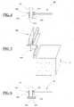
Fig. 4 représente une vue d'extrémité d'un rail de liaison pour un coffre-tunnel selon l'invention, - la
Fig. 5 représente une vue en perspective d'un rail de liaison et d'une patte d'ancrage de son extrémité dans une paroi murale, - la
Fig. 6 représente une vue d'extrémité d'une variante de réalisation d'un rail de liaison pour un coffre-tunnel, - la
Fig. 7 représente une vue en perspective d'un coffre-tunnel incorporant une armature de renforcement de sa structure selon l'invention, - la
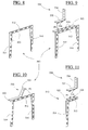
Fig. 8 représente une vue en perspective d'un arceau constitutif d'une armature pour un coffre-tunnel connu, - la
Fig. 9 représente une vue en perspective d'une première variante de réalisation d'un arceau constitutif d'une armature pour un coffre-tunnel selon l'invention, - la
Fig. 10 représente une vue en perspective d'une seconde variante de réalisation d'un arceau constitutif d'une armature pour un coffre-tunnel selon l'invention, - la
Fig. 11 représente une vue en perspective d'une troisième variante de réalisation d'un arceau constitutif d'une armature pour un coffre-tunnel selon l'invention et, - la
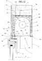
Fig. 12 représente une vue en coupe transversale d'un coffre-tunnel intégré à une construction d'un mur, au-dessus d'un tableau d'encadrement d'une fenêtre, un linteau recouvrant la paroi de voûte du coffre-tunnel selon l'invention. - Le coffre-tunnel 100, présenté sur la
Fig. 3 , est prévu pour être intégré dans une maçonnerie d'un bâtiment en cours de construction, au-dessus d'un tableau T délimitant l'encadrement de pose d'une fenêtre ou d'une porte. Il se présente sous la forme d'une pièce d'aspect prismatique qui est traversée longitudinalement d'un évidement E destiné à accueillir un mécanisme M de volet roulant comprenant un tambour d'enroulement O autour duquel peut être enroulé, déroulé un tablier d'occultation de la fenêtre, de la porte. L'évidement E débouche ainsi dans chacune des extrémités du coffre-tunnel et débouche également dans sa partie inférieure sur toute sa longueur pour permettre d'y loger le mécanisme de volet roulant et d'intervenir pour la maintenance, le cas échéant. - Le coffre-tunnel 100, présenté sur les
Figs. 2 et3 , est constitué d'un profilé délimité par une paroi de voûte V, prolongée par deux parois de jambage B1 et B2 (visibles distinctement sur laFig. 2 ) constituant la face avant et la face arrière du coffre-tunnel. L'évidement E est délimité entre ces parois. Le profilé est fabriqué en un matériau isolant d'un point de vue thermique. Dans un mode de fabrication avantageux, il est fabriqué en polystyrène expansé. Il est, de préférence, formé d'un bloc monolithique, d'un seul tenant. - Sur la
Fig. 3 , deux joues 200a et 200b ferment les extrémités latérales du coffre-tunnel. Chaque joue est constituée d'une paroi de fermeture d'une extrémité latérale et d'un rebord disposé perpendiculairement et dont la géométrie épouse le débouché de l'évidement E au travers de ladite extrémité latérale. Le mécanisme M de volet roulant est tenu entre ces deux joues. - Pour asseoir chacune des extrémités du coffre-tunnel sur des éléments de construction de la paroi murale P, deux profilés 320 et 340, visibles distinctement sur la
Fig. 2 , sont respectivement montés à cheval sur les bords libres des deux jambages B1 et B2. Leurs extrémités reposent ainsi sur les éléments de construction protégeant de la sorte les jambages. Par ailleurs, la présence de ces deux profilés permet de rigidifier les bords libres des deux jambages dont l'épaisseur est relativement faible. - Chaque profilé 320, 340 présente une section en U adaptée à chevaucher le bord libre du jambage correspondant. Une rainure 322, 342 creuse longitudinalement la branche intérieure de chaque profilé pour recevoir un chant latéral d'un talon 300 destiné à fermer localement l'évidement E et plus précisément la zone de l'évidement située à l'aplomb des éléments de construction.
- Ce placement du talon est distinctement visible sur cette
Fig. 3 . Le talon 300 est ainsi disposé dans le prolongement de la partie basse de chaque joue en étant tenu latéralement dans les deux profilés 320 et 340. Il est constitué d'une pièce indépendante d'aspect prismatique ou d'un prolongement de la joue formant avec elle une pièce monobloc. - Sur la
Fig. 2 , un rail de liaison 400 chevauche le bord libre d'un jambage et ici le jambage B2 pour relier le coffre-tunnel à la traverse supérieure TS d'un dormant D de fenêtre de porte. Cet agencement permet, en liant ces deux composants de limiter la déformation du dormant sous l'action du vent sur l'ouvrant Ov, tenu fermé dans le dormant. La direction du vent symbolisée par la flèche F tend en effet à cintrer la traverse supérieure TS qui n'est normalement pas ancrée au mur. On remarquera que le rail de liaison 400 recouvre le profilé 340. Ce profilé, qui accroît la rigidité du jambage, pourrait cependant, dans un mode de réalisation non représenté, être absent. Il est utile de rappeler qu'un vent d'une vitesse supérieure à 120 km/h peut exercer un différentiel de pression sur une fenêtre, une porte, qui peut atteindre 800 Pa. - Sur la vue en détail de la
Fig. 4 , le rail de liaison 400 est constitué d'un profilé de section en U comprenant une branche intermédiaire 410 prolongée de deux branches latérales 420, 430. La distance séparant les deux branches latérales 420 et 430 est telle qu'elles sont en contact avec les faces intérieure et extérieure du jambage B2, lorsque le profilé de liaison chevauche ledit jambage. - La branche intermédiaire constitue une plaque d'appui destinée à être solidarisée avec la traverse supérieure TS du dormant D. Cette branche intermédiaire 410 se prolonge en deçà des branches latérales 420, 430, pour procurer une rigidité importante au rail de liaison dans un plan parallèle à sa branche intermédiaire, c'est-à-dire dans la direction du vent, afin de limiter au maximum la déformation de la traverse supérieure TS.
- La position en hauteur du rail de liaison 400 sur le bord libre du jambage B2 peut être ajustée pour que la plaque d'appui 410 du rail de liaison 400 puisse être mise en contact avec la face supérieure de la traverse supérieure TS afin d'y être solidarisée. Cette plaque d'appui 410 est fixée, de préférence, par vissage sur la traverse supérieure TS.
- Dans une variante de réalisation montrée sur la
Fig. 2 , la plaque d'appui 410 est fixée par clippage dans un profilé de retenue 440 solidaire de la traverse supérieure TS. Ce profilé de retenue 440 comprend une paroi d'assise bordée latéralement de deux clips de retenue de la plaque d'appui. - Sur la
Fig. 4 , la branche latérale du rail de liaison 400, destinée à être tournée vers l'intérieur du coffre-tunnel, c'est-à-dire la branche 420, est pourvue d'une glissière 422 prévue pour loger un chant latéral d'une plaque de fermeture PF de l'évidement dans sa partie débouchant entre les talons. Cette plaque de fermeture est communément appelée sous-face. - La glissière 422 est constituée de deux arêtes parallèles qui font saillie perpendiculairement de ladite branche 420.
- Le rail de liaison 400 est fabriqué dans un matériau présentant une rigidité élevée comme de l'acier ou un matériau composite.
- Sur la
Fig. 5 , une patte d'ancrage 450 est fixée sur une extrémité du rail de liaison 400. Dans la pratique, l'autre extrémité du rail de liaison est aussi pourvue d'une telle patte d'ancrage 450. - Les pattes d'ancrage sont destinées à être scellées sur la paroi murale P pour tenir, par ses bouts, ce rail de liaison afin d'accroître son maintien et par ce fait accroître la rigidité du dormant auquel il est associé. Chaque patte d'ancrage présente sur cette
Fig. 5 une section transversale en Z comprenant une première paroi de fixation dans l'extrémité du rail de liaison, une seconde paroi intermédiaire et une troisième paroi de fixation sur la paroi murale. - Dans la variante de réalisation présentée sur la
Fig. 6 , la plaque d'appui 410 du rail de liaison 400 est creuse afin qu'elle puisse réceptionner une lame de rigidification 412 pour améliorer encore sa rigidité dans un plan transversal. - Ce rail de liaison 400 et ses accessoires sont des éléments de l'état de la technique qui sont utiles à la compréhension d'invention.
- Sur les
Figs. 2 ,3 ,7 et12 , le coffre-tunnel 100 intègre une armature 500 susceptible d'accroître sa rigidité dans une direction transversale afin de réduire la déformation de la paroi de jambage qui supporte le rail de liaison 400 par rapport à la partie complémentaire du coffre-tunnel. - Cette armature 500 comprend une pluralité d'arceaux 510 disposés régulièrement dans le coffre-tunnel et dans des plans transversaux à celui-ci. Chaque arceau 510 est intégré à l'intérieur des parois de voute V et de jambage B1 et B2 qui constituent le coffre-tunnel.
- L'arceau 510 présente sur la
Fig. 8 une géométrie en U retourné, comprenant une branche intermédiaire 512, prolongée respectivement de part et d'autre par deux branches 514 et 516 disposées parallèlement l'une à l'autre et orientées dans le même sens. La branche intermédiaire 512 de l'arceau est destinée à être placée au niveau de la paroi de voûte du coffre-tunnel alors que les branches 514 et 516 sont destinées à être placées au niveau de ses parois de jambage. Les branches sont également disposées dans un même plan. Leur épaisseur est quasi constante. La largeur de ces branches est plus importante que leur épaisseur pour procurer à l'arceau une grande - rigidité dans un plan tangent à celles-ci. L'arceau est de préférence fabriqué en métal ou dans un matériau composite pour lui procurer une grande raideur au regard de son encombrement. L'arceau est également de préférence fabriqué d'un seul tenant pour accroître sa rigidité. Les arceaux sont destinés à être placés à intervalles réguliers dans le moule de fabrication du coffre-tunnel, si bien qu'ils sont intégrés dans ses parois à l'issue de sa fabrication. Des passages 520 traversent l'arceau pour que la matière moulée puisse les traverser pendant la fabrication du coffre-tunnel et ainsi garantir une structure homogène au coffre-tunnel. Dans le même but, et comme cela apparaît sur la
Fig. 2 , l'épaisseur de la paroi de voute V, des parois de jambage B1, B2 du coffre-tunnel est plus grande que la largeur des branches de l'arceau. - On obtient de la sorte un coffre-tunnel dont les parois de jambage fléchissent moins lorsque l'on tente de les écarter ou de les rapprocher, lorsqu'on le compare à un coffre-tunnel conventionnel issu du même procédé de fabrication. La tenu du rail de liaison est réalisée plus fermement par le coffre-tunnel et il en résulte une moindre déformation du dormant.
- Grâce à la présence des ces arceaux, il est apparu intéressant de pouvoir accroître l'ancrage du coffre-tunnel avec le linteau qui le surplombe pour lier davantage le dormant avec le linteau. De manière traditionnelle, on peut couler un linteau au dessus d'un coffre-tunnel préalablement assis de chaque côté d'éléments de maçonnerie délimitant latéralement le tableau. Des rainures longitudinales R sont prévues, sur la
Fig. 2 , dans la paroi de voûte du coffre-tunnel, pour que le liant liquide puisse s'y répandre afin de rendre solidaire le coffre-tunnel avec le linteau à l'issue de sa solidification. Le linteau peut encore être constitué d'une pièce qui est rapportée et il est alors solidarisé par un liant au coffre-tunnel qu'il convient d'interposer entre ces deux pièces. - Sur la
Fig. 9 , l'arceau 510 peut être solidarisé à une patte d'ancrage 530 avec un linteau. Une paroi de support 522 de la patte d'ancrage prolonge perpendiculairement la branche intermédiaire 512 dans sa partie haute. Elle est traversée d'encoches 524. La patte d'ancrage 530 est constituée d'une pièce présentant en vue latérale une géométrie en L comprenant une paroi 532 d'assise sur la paroi de support 522, prolongée par une paroi de liaison 534 avec le linteau. Des tenons 536 sont disposés sous la paroi d'assise 532 pour coopérer par accrochage avec les encoches 524 afin que ladite patte d'ancrage puisse être rendue solidaire de l'arceau 510, comme le suggère la flèche F1. Selon que le linteau est coulé ou est rapporté, la patte d'ancrage 530 est rendue solidaire du linteau par coulage de béton emprisonnant la paroi de liaison 534 ou en fixant cette paroi de liaison sur une face du linteau. Des trous traversent à cet effet ladite paroi de liaison. - L'arceau 510 présenté en référence à la
Fig. 8 et qui est dépourvu de paroi de support 522, illustre l'état de la technique qui est utile à la compréhension de l'invention. - Dans sa version présentée sur la
Fig. 10 , la patte d'ancrage 530 est intégrée à la structure de l'arceau 510. Sa paroi de support 522 n'est relié que partiellement à la branche intermédiaire 512, si bien qu'il est possible de replier la partie libre de cette paroi de support pour former une paroi de liaison 534, comme le suggère la flèche F2. - Sur la
Fig. 11 , l'arceau 510 affecte une géométrie en L retourné comprenant une branche intermédiaire 512 reliée à une seule branche 514 prévue pour renforcer la paroi de jambage qui supporte le rail de liaison. Ce rail de liaison peut alors être rendu solidaire du linteau pour réduire encore la déformation du dormant sous l'effet du vent. Ce rail convient pour être intégré à la construction d'un coffre-tunnel du type comprenant une paroi de voûte et une seule paroi de jambage. - Sur la
Fig. 12 , un linteau L a été coulé au-dessus du coffre-tunnel 100 et la paroi de liaison 534 de la patte d'ancrage 530 est noyée dans celui-ci. Un enduit Ep de protection est appliqué sur la paroi du coffre-tunnel qui est tournée vers l'extérieur. On dépose encore du plâtre Pl présenté sous la forme de plaques contre la paroi interne du mur P par-dessus un isolant Is et de manière à masquer le coffre-tunnel 100. - Sur les
Figs. 2 ,7 et12 , l'armature 500 du coffre-tunnel 100 comporte encore des tiges de renfort 550 disposées longitudinalement dans la paroi de voûte V et/ou dans les parois de jambage B1, B2 pour réduire la déformation sous contrainte de ces parois. Les tiges de renfort 550 traversent avantageusement des trous 552 prévus dans les branches des arceaux 510 pour que des efforts appliqués sur les parois de jambage soient uniformément répartis sur toute la longueur du coffre-tunnel. Les parois de jambage B1, B2, conservent alors leur planéité. - Le coffre-tunnel de l'invention est avantageusement utilisé avec un rail de liaison adapté pour chevaucher le bord libre d'un jambage qui le constitue afin que ce rail de liaison puisse être solidarisé sur la traverse supérieure d'un dormant pour la rigidifier. Il peut cependant être utilisé sans ce rail de liaison en bénéficiant des avantages de sa structure rigidifiée.
- Le coffre-tunnel de l'invention présente une structure renforcée par rapport à un coffre-tunnel antérieur.
- Il est avantageusement associé à la partie haute d'un dormant pour le renforcer, en la reliant avec la paroi murale pour réduire la déformation du dormant sous l'effet de l'action du vent.
- Le coffre-tunnel de l'invention permet de renforcer la liaison de la traverse supérieure du dormant avec la paroi murale. Il facilite la mise en conformité de la fenêtre, de la porte avec les normes EN 12210 et EN 12211 se rapportant aux déformations admissibles au vent de tels dispositifs de fermeture.
- Son coût de fabrication est intéressant, au regard des avantages qu'il procure.
Claims (6)
- Coffre-tunnel (100) destiné à réceptionner un mécanisme (M) de fermeture à volet roulant, le coffre-tunnel étant prévu pour être ancré au-dessus d'un tableau (T) délimitant l'encadrement de pose d'un dormant d'une fenêtre ou d'une porte, le coffre-tunnel comprenant une paroi de voûte (V) prolongée par au moins une paroi de jambage (B1, B2), le coffre-tunnel étant fabriqué en un même matériau isolant d'un point de vue thermique, le coffre-tunnel incorporant une armature (500) conçue pour rigidifier sa structure, l'armature comprenant une pluralité d'arceaux (510) intégrée par surmoulage dans les parois du coffre-tunnel dans des plans transversaux de celui-ci, des passages (520) traversant chaque arceau (510) pour que la matière moulée puisse les traverser pendant la fabrication du coffre-tunnel, afin de les intégrer dans la structure du coffre-tunnel (100) à l'issue de sa fabrication, chaque arceau comprenant une branche intermédiaire (512) disposée au niveau de la paroi de voûte (V) du coffre-tunnel, une paroi de support (522) prolongeant perpendiculairement ladite branche intermédiaire dans sa partie haute, caractérisé en ce que la paroi de support (522) est partiellement reliée à ladite branche intermédiaire, permettant de replier la partie libre de cette paroi de support pour former une paroi de liaison (534) avec un linteau ou en ce que le coffre-tunnel comprend une patte d'ancrage (530) à un linteau et la paroi de support est traversée d'encoches (524) conçues pour coopérer avec des tenons (536) correspondants de la patte d'ancrage (530).
- Coffre-tunnel (100) selon la revendication 1, caractérisé en ce que la patte d'ancrage (530) est constituée d'une pièce présentant en vue latérale une géométrie en L comprenant une paroi d'assise (532) sur la paroi de support (522), prolongée par une paroi de liaison (534) au linteau (L), les tenons (536) étant disposés sous la paroi d'assise (532).
- Coffre-tunnel (100) selon la revendication 1 ou 2, caractérisé en ce que la branche intermédiaire (512) est prolongée respectivement de part et d'autre par deux branches (514 et 516) disposées respectivement au niveau des parois de jambage (B1, B2).
- Coffre-tunnel (100) selon la revendication 1 ou 2, caractérisé en ce que la branche intermédiaire (512) est prolongée d'un bord par une seule branche (514) disposée au niveau d'une paroi de jambage.
- Coffre-tunnel (100) selon l'une quelconque des revendications précédentes, caractérisé en ce que l'armature (500) comprend des tiges (550) de renfort disposées longitudinalement dans la paroi de voûte (V) et/ou dans les parois de jambage (B1, B2) pour réduire la déformation sous contrainte de ces parois.
- Coffre-tunnel (100) selon la revendication 5, caractérisé en ce que les tiges (550) traversent des trous (552) prévus dans les branches des arceaux (510) pour que des efforts appliqués sur les parois de jambage soient uniformément répartis sur toute la longueur du coffre-tunnel.
Applications Claiming Priority (1)
| Application Number | Priority Date | Filing Date | Title |
|---|---|---|---|
| FR1051988A FR2957627B1 (fr) | 2010-03-19 | 2010-03-19 | Coffre-tunnel incorporant une armature de renfort de sa structure |
Publications (2)
| Publication Number | Publication Date |
|---|---|
| EP2366863A1 EP2366863A1 (fr) | 2011-09-21 |
| EP2366863B1 true EP2366863B1 (fr) | 2015-10-28 |
Family
ID=43500378
Family Applications (1)
| Application Number | Title | Priority Date | Filing Date |
|---|---|---|---|
| EP11158790.3A Active EP2366863B1 (fr) | 2010-03-19 | 2011-03-18 | Coffre-tunnel incorporant une armature de renfort de sa structure |
Country Status (4)
| Country | Link |
|---|---|
| EP (1) | EP2366863B1 (fr) |
| ES (1) | ES2561666T3 (fr) |
| FR (1) | FR2957627B1 (fr) |
| PT (1) | PT2366863E (fr) |
Families Citing this family (3)
| Publication number | Priority date | Publication date | Assignee | Title |
|---|---|---|---|---|
| FR2999220B1 (fr) * | 2012-12-07 | 2015-08-07 | Soprofen | Ensemble de coffre de volet roulant avec coffre en materiau isolant thermique |
| FR3005678B1 (fr) * | 2013-05-15 | 2015-05-22 | Fixolite Sa | Armature pour coffre de volet |
| FR3023573B1 (fr) * | 2014-07-08 | 2021-05-07 | Fixolite Sa | Interface de fixation pour coffre de volet |
Family Cites Families (7)
| Publication number | Priority date | Publication date | Assignee | Title |
|---|---|---|---|---|
| ATE95882T1 (de) * | 1986-03-22 | 1993-10-15 | Augsburger Ver Ziegelwerke | Vorgefertigter rolladenkasten aus aneinanderstossenden ziegelformsteinen, sowie verfahren zur herstellung desselben. |
| DE10034533A1 (de) * | 2000-07-15 | 2002-01-24 | Beck Bernd | Stabilisator und Rolladenkasten mit Stabilisator |
| DE20311385U1 (de) * | 2003-02-18 | 2004-04-01 | Führer, Josef | Rolladenkasten |
| DE10347717B4 (de) * | 2003-06-25 | 2016-12-29 | Beck & Heun Gmbh | Rolladenkasten |
| FR2895438B1 (fr) * | 2005-12-27 | 2009-07-17 | Eveno Sas Soc Par Actions Simp | Coffre-tunnel pour volet roulant et son procede de fabrication |
| DE102006038401A1 (de) * | 2006-08-15 | 2008-02-21 | Exte-Extrudertechnik Gmbh | Auf einen Rahmen, nämlich einen Fenster- oder Türrahmen aufzusetzender Rollladenkasten |
| WO2009058269A1 (fr) | 2007-10-29 | 2009-05-07 | Jan Vetrovec | Dispositif de transfert de chaleur |
-
2010
- 2010-03-19 FR FR1051988A patent/FR2957627B1/fr active Active
-
2011
- 2011-03-18 PT PT111587903T patent/PT2366863E/pt unknown
- 2011-03-18 EP EP11158790.3A patent/EP2366863B1/fr active Active
- 2011-03-18 ES ES11158790.3T patent/ES2561666T3/es active Active
Also Published As
| Publication number | Publication date |
|---|---|
| FR2957627B1 (fr) | 2013-12-06 |
| EP2366863A1 (fr) | 2011-09-21 |
| FR2957627A1 (fr) | 2011-09-23 |
| PT2366863E (pt) | 2015-11-26 |
| ES2561666T3 (es) | 2016-02-29 |
Similar Documents
| Publication | Publication Date | Title |
|---|---|---|
| EP2580417B1 (fr) | Structure de bloc-porte | |
| EP2366863B1 (fr) | Coffre-tunnel incorporant une armature de renfort de sa structure | |
| EP3242980B1 (fr) | Module perfectionné formant rupteur de pont thermique pour bâtiments isolés par l'extérieur | |
| EP1994252B1 (fr) | Installation de volet roulant dans une ouverture de batiment, demi-bloc baie pour une telle installation, et procede pour installer le volet roulant. | |
| FR2992017A1 (fr) | Coffre-tunnel incorporant une patte de fixation entre un linteau et le dormant d'une menuiserie | |
| EP2580419B1 (fr) | Bloc-porte coupe feu a un ou deux vantaux pivotant(s) | |
| WO2012010773A1 (fr) | Bloc de coffrage isolant | |
| FR2927645A1 (fr) | Coffre-tunnel bi-matiere pour volet roulant | |
| FR2957965A1 (fr) | Porte de garage isolee | |
| FR2974592A1 (fr) | Equipement de baie et coffre a volet roulant renforce faisant partie de cet equipement | |
| EP2740877B1 (fr) | Ensemble de coffre de volet roulant avec coffre en matériau isolant thermique | |
| EP2325434B1 (fr) | Coffre-tunnel pourvu d'un rail de liaison pour un dormant | |
| EP2947257B1 (fr) | Coffre-tunnel pourvu d'un puits de réception pour un moyen de liaison entre un linteau et un dormant d'huisserie | |
| EP2949856B1 (fr) | Coffre-tunnel creusé d'une rainure de logement pour une patte de fixation et incorporant une armature de renfort | |
| EP2325432B1 (fr) | Corps de coffre de volet roulant et dispositif de coffre comprenant un tel corps | |
| EP2899327B1 (fr) | Elément de construction isolant et procédé pour sa fabrication | |
| EP3372770A1 (fr) | Installation de fenetre coulissante pour batiment | |
| FR3007440A1 (fr) | Bloc coffrant integrant un pre-cadre d'huisserie | |
| EP1020610B1 (fr) | Jambage et coffre de volet roulant | |
| FR2952962A1 (fr) | Coffre-tunnel pourvu d'un rail de liaison pour un dormant. | |
| EP1972750B1 (fr) | Coulisse de guidage de tablier de volet roulant | |
| FR3024487A1 (fr) | Structure de menuiserie comprenant un dormant et un coffre de volet roulant | |
| FR3018532A1 (fr) | Accessoire linteau | |
| WO2023131756A1 (fr) | Cadre isolant pour recevoir une menuiserie | |
| FR2930794A1 (fr) | Element de coffrage et procede de costruction d'une maconnerie |
Legal Events
| Date | Code | Title | Description |
|---|---|---|---|
| PUAI | Public reference made under article 153(3) epc to a published international application that has entered the european phase |
Free format text: ORIGINAL CODE: 0009012 |
|
| AK | Designated contracting states |
Kind code of ref document: A1 Designated state(s): AL AT BE BG CH CY CZ DE DK EE ES FI FR GB GR HR HU IE IS IT LI LT LU LV MC MK MT NL NO PL PT RO RS SE SI SK SM TR |
|
| AX | Request for extension of the european patent |
Extension state: BA ME |
|
| 17P | Request for examination filed |
Effective date: 20120326 |
|
| 17Q | First examination report despatched |
Effective date: 20141022 |
|
| GRAP | Despatch of communication of intention to grant a patent |
Free format text: ORIGINAL CODE: EPIDOSNIGR1 |
|
| INTG | Intention to grant announced |
Effective date: 20150515 |
|
| GRAS | Grant fee paid |
Free format text: ORIGINAL CODE: EPIDOSNIGR3 |
|
| GRAA | (expected) grant |
Free format text: ORIGINAL CODE: 0009210 |
|
| AK | Designated contracting states |
Kind code of ref document: B1 Designated state(s): AL AT BE BG CH CY CZ DE DK EE ES FI FR GB GR HR HU IE IS IT LI LT LU LV MC MK MT NL NO PL PT RO RS SE SI SK SM TR |
|
| REG | Reference to a national code |
Ref country code: GB Ref legal event code: FG4D Free format text: NOT ENGLISH |
|
| REG | Reference to a national code |
Ref country code: CH Ref legal event code: EP |
|
| REG | Reference to a national code |
Ref country code: AT Ref legal event code: REF Ref document number: 758050 Country of ref document: AT Kind code of ref document: T Effective date: 20151115 |
|
| REG | Reference to a national code |
Ref country code: IE Ref legal event code: FG4D Free format text: LANGUAGE OF EP DOCUMENT: FRENCH |
|
| REG | Reference to a national code |
Ref country code: PT Ref legal event code: SC4A Free format text: AVAILABILITY OF NATIONAL TRANSLATION Effective date: 20151110 |
|
| REG | Reference to a national code |
Ref country code: DE Ref legal event code: R096 Ref document number: 602011020941 Country of ref document: DE |
|
| REG | Reference to a national code |
Ref country code: LT Ref legal event code: MG4D |
|
| REG | Reference to a national code |
Ref country code: ES Ref legal event code: FG2A Ref document number: 2561666 Country of ref document: ES Kind code of ref document: T3 Effective date: 20160229 |
|
| REG | Reference to a national code |
Ref country code: NL Ref legal event code: MP Effective date: 20151028 |
|
| REG | Reference to a national code |
Ref country code: AT Ref legal event code: MK05 Ref document number: 758050 Country of ref document: AT Kind code of ref document: T Effective date: 20151028 |
|
| REG | Reference to a national code |
Ref country code: FR Ref legal event code: PLFP Year of fee payment: 6 |
|
| PG25 | Lapsed in a contracting state [announced via postgrant information from national office to epo] |
Ref country code: NL Free format text: LAPSE BECAUSE OF FAILURE TO SUBMIT A TRANSLATION OF THE DESCRIPTION OR TO PAY THE FEE WITHIN THE PRESCRIBED TIME-LIMIT Effective date: 20151028 Ref country code: HR Free format text: LAPSE BECAUSE OF FAILURE TO SUBMIT A TRANSLATION OF THE DESCRIPTION OR TO PAY THE FEE WITHIN THE PRESCRIBED TIME-LIMIT Effective date: 20151028 Ref country code: IS Free format text: LAPSE BECAUSE OF FAILURE TO SUBMIT A TRANSLATION OF THE DESCRIPTION OR TO PAY THE FEE WITHIN THE PRESCRIBED TIME-LIMIT Effective date: 20160228 Ref country code: NO Free format text: LAPSE BECAUSE OF FAILURE TO SUBMIT A TRANSLATION OF THE DESCRIPTION OR TO PAY THE FEE WITHIN THE PRESCRIBED TIME-LIMIT Effective date: 20160128 Ref country code: LT Free format text: LAPSE BECAUSE OF FAILURE TO SUBMIT A TRANSLATION OF THE DESCRIPTION OR TO PAY THE FEE WITHIN THE PRESCRIBED TIME-LIMIT Effective date: 20151028 |
|
| PG25 | Lapsed in a contracting state [announced via postgrant information from national office to epo] |
Ref country code: AT Free format text: LAPSE BECAUSE OF FAILURE TO SUBMIT A TRANSLATION OF THE DESCRIPTION OR TO PAY THE FEE WITHIN THE PRESCRIBED TIME-LIMIT Effective date: 20151028 Ref country code: LV Free format text: LAPSE BECAUSE OF FAILURE TO SUBMIT A TRANSLATION OF THE DESCRIPTION OR TO PAY THE FEE WITHIN THE PRESCRIBED TIME-LIMIT Effective date: 20151028 Ref country code: SE Free format text: LAPSE BECAUSE OF FAILURE TO SUBMIT A TRANSLATION OF THE DESCRIPTION OR TO PAY THE FEE WITHIN THE PRESCRIBED TIME-LIMIT Effective date: 20151028 Ref country code: FI Free format text: LAPSE BECAUSE OF FAILURE TO SUBMIT A TRANSLATION OF THE DESCRIPTION OR TO PAY THE FEE WITHIN THE PRESCRIBED TIME-LIMIT Effective date: 20151028 Ref country code: GR Free format text: LAPSE BECAUSE OF FAILURE TO SUBMIT A TRANSLATION OF THE DESCRIPTION OR TO PAY THE FEE WITHIN THE PRESCRIBED TIME-LIMIT Effective date: 20160129 Ref country code: PL Free format text: LAPSE BECAUSE OF FAILURE TO SUBMIT A TRANSLATION OF THE DESCRIPTION OR TO PAY THE FEE WITHIN THE PRESCRIBED TIME-LIMIT Effective date: 20151028 Ref country code: RS Free format text: LAPSE BECAUSE OF FAILURE TO SUBMIT A TRANSLATION OF THE DESCRIPTION OR TO PAY THE FEE WITHIN THE PRESCRIBED TIME-LIMIT Effective date: 20151028 |
|
| PG25 | Lapsed in a contracting state [announced via postgrant information from national office to epo] |
Ref country code: CZ Free format text: LAPSE BECAUSE OF FAILURE TO SUBMIT A TRANSLATION OF THE DESCRIPTION OR TO PAY THE FEE WITHIN THE PRESCRIBED TIME-LIMIT Effective date: 20151028 |
|
| REG | Reference to a national code |
Ref country code: DE Ref legal event code: R097 Ref document number: 602011020941 Country of ref document: DE |
|
| PG25 | Lapsed in a contracting state [announced via postgrant information from national office to epo] |
Ref country code: EE Free format text: LAPSE BECAUSE OF FAILURE TO SUBMIT A TRANSLATION OF THE DESCRIPTION OR TO PAY THE FEE WITHIN THE PRESCRIBED TIME-LIMIT Effective date: 20151028 Ref country code: RO Free format text: LAPSE BECAUSE OF FAILURE TO SUBMIT A TRANSLATION OF THE DESCRIPTION OR TO PAY THE FEE WITHIN THE PRESCRIBED TIME-LIMIT Effective date: 20151028 Ref country code: DK Free format text: LAPSE BECAUSE OF FAILURE TO SUBMIT A TRANSLATION OF THE DESCRIPTION OR TO PAY THE FEE WITHIN THE PRESCRIBED TIME-LIMIT Effective date: 20151028 Ref country code: BE Free format text: LAPSE BECAUSE OF NON-PAYMENT OF DUE FEES Effective date: 20160331 Ref country code: SK Free format text: LAPSE BECAUSE OF FAILURE TO SUBMIT A TRANSLATION OF THE DESCRIPTION OR TO PAY THE FEE WITHIN THE PRESCRIBED TIME-LIMIT Effective date: 20151028 Ref country code: SM Free format text: LAPSE BECAUSE OF FAILURE TO SUBMIT A TRANSLATION OF THE DESCRIPTION OR TO PAY THE FEE WITHIN THE PRESCRIBED TIME-LIMIT Effective date: 20151028 |
|
| PLBE | No opposition filed within time limit |
Free format text: ORIGINAL CODE: 0009261 |
|
| STAA | Information on the status of an ep patent application or granted ep patent |
Free format text: STATUS: NO OPPOSITION FILED WITHIN TIME LIMIT |
|
| 26N | No opposition filed |
Effective date: 20160729 |
|
| PG25 | Lapsed in a contracting state [announced via postgrant information from national office to epo] |
Ref country code: MC Free format text: LAPSE BECAUSE OF FAILURE TO SUBMIT A TRANSLATION OF THE DESCRIPTION OR TO PAY THE FEE WITHIN THE PRESCRIBED TIME-LIMIT Effective date: 20151028 Ref country code: LU Free format text: LAPSE BECAUSE OF FAILURE TO SUBMIT A TRANSLATION OF THE DESCRIPTION OR TO PAY THE FEE WITHIN THE PRESCRIBED TIME-LIMIT Effective date: 20160318 |
|
| REG | Reference to a national code |
Ref country code: CH Ref legal event code: PL |
|
| GBPC | Gb: european patent ceased through non-payment of renewal fee |
Effective date: 20160318 |
|
| PG25 | Lapsed in a contracting state [announced via postgrant information from national office to epo] |
Ref country code: SI Free format text: LAPSE BECAUSE OF FAILURE TO SUBMIT A TRANSLATION OF THE DESCRIPTION OR TO PAY THE FEE WITHIN THE PRESCRIBED TIME-LIMIT Effective date: 20151028 |
|
| REG | Reference to a national code |
Ref country code: IE Ref legal event code: MM4A |
|
| PG25 | Lapsed in a contracting state [announced via postgrant information from national office to epo] |
Ref country code: IE Free format text: LAPSE BECAUSE OF NON-PAYMENT OF DUE FEES Effective date: 20160318 Ref country code: GB Free format text: LAPSE BECAUSE OF NON-PAYMENT OF DUE FEES Effective date: 20160318 Ref country code: CH Free format text: LAPSE BECAUSE OF NON-PAYMENT OF DUE FEES Effective date: 20160331 Ref country code: LI Free format text: LAPSE BECAUSE OF NON-PAYMENT OF DUE FEES Effective date: 20160331 |
|
| REG | Reference to a national code |
Ref country code: FR Ref legal event code: PLFP Year of fee payment: 7 |
|
| PG25 | Lapsed in a contracting state [announced via postgrant information from national office to epo] |
Ref country code: MT Free format text: LAPSE BECAUSE OF FAILURE TO SUBMIT A TRANSLATION OF THE DESCRIPTION OR TO PAY THE FEE WITHIN THE PRESCRIBED TIME-LIMIT Effective date: 20151028 |
|
| REG | Reference to a national code |
Ref country code: FR Ref legal event code: PLFP Year of fee payment: 8 |
|
| PG25 | Lapsed in a contracting state [announced via postgrant information from national office to epo] |
Ref country code: HU Free format text: LAPSE BECAUSE OF FAILURE TO SUBMIT A TRANSLATION OF THE DESCRIPTION OR TO PAY THE FEE WITHIN THE PRESCRIBED TIME-LIMIT; INVALID AB INITIO Effective date: 20110318 Ref country code: CY Free format text: LAPSE BECAUSE OF FAILURE TO SUBMIT A TRANSLATION OF THE DESCRIPTION OR TO PAY THE FEE WITHIN THE PRESCRIBED TIME-LIMIT Effective date: 20151028 |
|
| PG25 | Lapsed in a contracting state [announced via postgrant information from national office to epo] |
Ref country code: TR Free format text: LAPSE BECAUSE OF FAILURE TO SUBMIT A TRANSLATION OF THE DESCRIPTION OR TO PAY THE FEE WITHIN THE PRESCRIBED TIME-LIMIT Effective date: 20151028 Ref country code: MK Free format text: LAPSE BECAUSE OF FAILURE TO SUBMIT A TRANSLATION OF THE DESCRIPTION OR TO PAY THE FEE WITHIN THE PRESCRIBED TIME-LIMIT Effective date: 20151028 |
|
| PG25 | Lapsed in a contracting state [announced via postgrant information from national office to epo] |
Ref country code: BG Free format text: LAPSE BECAUSE OF FAILURE TO SUBMIT A TRANSLATION OF THE DESCRIPTION OR TO PAY THE FEE WITHIN THE PRESCRIBED TIME-LIMIT Effective date: 20151028 |
|
| PG25 | Lapsed in a contracting state [announced via postgrant information from national office to epo] |
Ref country code: AL Free format text: LAPSE BECAUSE OF FAILURE TO SUBMIT A TRANSLATION OF THE DESCRIPTION OR TO PAY THE FEE WITHIN THE PRESCRIBED TIME-LIMIT Effective date: 20151028 |
|
| PGFP | Annual fee paid to national office [announced via postgrant information from national office to epo] |
Ref country code: FR Payment date: 20230322 Year of fee payment: 13 |
|
| PGFP | Annual fee paid to national office [announced via postgrant information from national office to epo] |
Ref country code: IT Payment date: 20230328 Year of fee payment: 13 Ref country code: ES Payment date: 20230529 Year of fee payment: 13 |
|
| PGFP | Annual fee paid to national office [announced via postgrant information from national office to epo] |
Ref country code: DE Payment date: 20240320 Year of fee payment: 14 Ref country code: PT Payment date: 20240307 Year of fee payment: 14 |