EP2364892A1 - Fahrzeuglaufsteuerung - Google Patents
Fahrzeuglaufsteuerung Download PDFInfo
- Publication number
- EP2364892A1 EP2364892A1 EP09830134A EP09830134A EP2364892A1 EP 2364892 A1 EP2364892 A1 EP 2364892A1 EP 09830134 A EP09830134 A EP 09830134A EP 09830134 A EP09830134 A EP 09830134A EP 2364892 A1 EP2364892 A1 EP 2364892A1
- Authority
- EP
- European Patent Office
- Prior art keywords
- vehicle speed
- driving force
- target
- mode
- upper limit
- Prior art date
- Legal status (The legal status is an assumption and is not a legal conclusion. Google has not performed a legal analysis and makes no representation as to the accuracy of the status listed.)
- Granted
Links
Images


Classifications
-
- F—MECHANICAL ENGINEERING; LIGHTING; HEATING; WEAPONS; BLASTING
- F02—COMBUSTION ENGINES; HOT-GAS OR COMBUSTION-PRODUCT ENGINE PLANTS
- F02D—CONTROLLING COMBUSTION ENGINES
- F02D29/00—Controlling engines, such controlling being peculiar to the devices driven thereby, the devices being other than parts or accessories essential to engine operation, e.g. controlling of engines by signals external thereto
- F02D29/02—Controlling engines, such controlling being peculiar to the devices driven thereby, the devices being other than parts or accessories essential to engine operation, e.g. controlling of engines by signals external thereto peculiar to engines driving vehicles; peculiar to engines driving variable pitch propellers
-
- B—PERFORMING OPERATIONS; TRANSPORTING
- B60—VEHICLES IN GENERAL
- B60W—CONJOINT CONTROL OF VEHICLE SUB-UNITS OF DIFFERENT TYPE OR DIFFERENT FUNCTION; CONTROL SYSTEMS SPECIALLY ADAPTED FOR HYBRID VEHICLES; ROAD VEHICLE DRIVE CONTROL SYSTEMS FOR PURPOSES NOT RELATED TO THE CONTROL OF A PARTICULAR SUB-UNIT
- B60W30/00—Purposes of road vehicle drive control systems not related to the control of a particular sub-unit, e.g. of systems using conjoint control of vehicle sub-units, or advanced driver assistance systems for ensuring comfort, stability and safety or drive control systems for propelling or retarding the vehicle
- B60W30/14—Adaptive cruise control
- B60W30/143—Speed control
-
- B—PERFORMING OPERATIONS; TRANSPORTING
- B60—VEHICLES IN GENERAL
- B60W—CONJOINT CONTROL OF VEHICLE SUB-UNITS OF DIFFERENT TYPE OR DIFFERENT FUNCTION; CONTROL SYSTEMS SPECIALLY ADAPTED FOR HYBRID VEHICLES; ROAD VEHICLE DRIVE CONTROL SYSTEMS FOR PURPOSES NOT RELATED TO THE CONTROL OF A PARTICULAR SUB-UNIT
- B60W2552/00—Input parameters relating to infrastructure
- B60W2552/15—Road slope
-
- B—PERFORMING OPERATIONS; TRANSPORTING
- B60—VEHICLES IN GENERAL
- B60W—CONJOINT CONTROL OF VEHICLE SUB-UNITS OF DIFFERENT TYPE OR DIFFERENT FUNCTION; CONTROL SYSTEMS SPECIALLY ADAPTED FOR HYBRID VEHICLES; ROAD VEHICLE DRIVE CONTROL SYSTEMS FOR PURPOSES NOT RELATED TO THE CONTROL OF A PARTICULAR SUB-UNIT
- B60W2710/00—Output or target parameters relating to a particular sub-units
- B60W2710/10—Change speed gearings
- B60W2710/1061—Output power
-
- B—PERFORMING OPERATIONS; TRANSPORTING
- B60—VEHICLES IN GENERAL
- B60W—CONJOINT CONTROL OF VEHICLE SUB-UNITS OF DIFFERENT TYPE OR DIFFERENT FUNCTION; CONTROL SYSTEMS SPECIALLY ADAPTED FOR HYBRID VEHICLES; ROAD VEHICLE DRIVE CONTROL SYSTEMS FOR PURPOSES NOT RELATED TO THE CONTROL OF A PARTICULAR SUB-UNIT
- B60W2720/00—Output or target parameters relating to overall vehicle dynamics
- B60W2720/10—Longitudinal speed
-
- Y—GENERAL TAGGING OF NEW TECHNOLOGICAL DEVELOPMENTS; GENERAL TAGGING OF CROSS-SECTIONAL TECHNOLOGIES SPANNING OVER SEVERAL SECTIONS OF THE IPC; TECHNICAL SUBJECTS COVERED BY FORMER USPC CROSS-REFERENCE ART COLLECTIONS [XRACs] AND DIGESTS
- Y02—TECHNOLOGIES OR APPLICATIONS FOR MITIGATION OR ADAPTATION AGAINST CLIMATE CHANGE
- Y02T—CLIMATE CHANGE MITIGATION TECHNOLOGIES RELATED TO TRANSPORTATION
- Y02T10/00—Road transport of goods or passengers
- Y02T10/10—Internal combustion engine [ICE] based vehicles
- Y02T10/40—Engine management systems
-
- Y—GENERAL TAGGING OF NEW TECHNOLOGICAL DEVELOPMENTS; GENERAL TAGGING OF CROSS-SECTIONAL TECHNOLOGIES SPANNING OVER SEVERAL SECTIONS OF THE IPC; TECHNICAL SUBJECTS COVERED BY FORMER USPC CROSS-REFERENCE ART COLLECTIONS [XRACs] AND DIGESTS
- Y02—TECHNOLOGIES OR APPLICATIONS FOR MITIGATION OR ADAPTATION AGAINST CLIMATE CHANGE
- Y02T—CLIMATE CHANGE MITIGATION TECHNOLOGIES RELATED TO TRANSPORTATION
- Y02T10/00—Road transport of goods or passengers
- Y02T10/80—Technologies aiming to reduce greenhouse gasses emissions common to all road transportation technologies
- Y02T10/84—Data processing systems or methods, management, administration
Definitions
- the present invention relates to a running control device for a vehicle in which constant speed running is possible.
- Priority is claimed on Japanese Patent Application No. 2008-309918, filed on December 4, 2008 , the contents of which are incorporated herein by reference.
- a running control device for a vehicle performs constant speed running control (hereinafter referred to as cruise control) by comparing the actual vehicle speed with a target vehicle speed set by the driver and adjusting acceleration and deceleration of the vehicle such that the actual vehicle speed corresponds with the target vehicle speed.
- the running control device for a vehicle described in, for example, Patent Document 1 described below can carry out the cruise control by a normal mode and the cruise control by a fuel-efficient mode in which fuel efficiency is improved more than in the normal mode.
- the upper limit value of the number of engine rotations in the fuel-efficient mode and the upper limit value of the number of engine rotations in the normal mode are different from each other.
- the present invention has an object to provide a running control device for a vehicle, in which improvement in fuel efficiency in cruise control is attained by performing restriction of a driving force.
- the present invention adopts the following means in order to solve the above-mentioned problem, thereby achieving such an object. That is,
- hypersensitive reaction of a driving force to a load variation caused from unevenness or the like of a road surface can be suppressed by restricting the target driving force to be less than or equal to the target driving force upper limit value.
- the allowed lowering value is set such that the larger the target driving force upper limit value, the larger the allowed lowering value. For this reason, since the larger the set target driving force upper limit value, the more an area of output restriction by the target driving force upper limit value can be expanded, an area having a fuel efficiency effect can be expanded without a sense of discomfort.
- the provisional target vehicle speed is set. Then, by using this in place of the original target vehicle speed, the target driving force is calculated. For this reason, a rapid increase in a driving force at the time of the switching of the target driving force upper limit value can be prevented. Also, by gradually approximating (transitioning) the provisional target vehicle speed to the original target vehicle speed, recovery control which returns the lowered vehicle speed to the original target vehicle speed can be carried out without sudden acceleration. Accordingly, return to an original control state can be performed with the output of a small driving force.
- the variation restriction value per unit time of the provisional target vehicle speed is calculated based on the actual vehicle speed or a deviation of the actual vehicle speed from the original target vehicle speed. Accordingly, since it is possible to set an optimal variation restriction value in accordance with the actual vehicle speed, improvement in fuel efficiency can be attained. Also, the provisional target vehicle speed can be returned to the original target vehicle speed without causing a sense of discomfort to a driver.
- the value of the current actual vehicle speed is set as the provisional target vehicle speed or the provisional target vehicle speed is increased more than or equal to the variation restriction value. Accordingly, since the provisional target vehicle speed increases to the usual or greater, the actual vehicle speed can quickly converge to the original target vehicle speed.
- the target driving force upper limit value can be more finely set with respect to a load variation.
- the driver feels a sense of discomfort. Therefore, if the variation restriction value is set to be large at the time of a downhill gradient, it is possible to not make the driver feel such a sense of discomfort.
- the driver can select any one of driving force control which is subjected to restriction of the target driving force upper limit value in the normal mode and driving force control which is subjected to restriction of the target driving force upper limit value in the fuel-efficient mode.
- the running control device for a vehicle in the cruise control, restriction of a driving force can be performed. Accordingly, since the driving force of the engine can be accurately restricted regardless of the vehicle speed or the state of a driving force transmission device, fuel efficiency in the cruise control can be improved.
- FIGS. 1 to 13 a running control device for a vehicle according to an embodiment of the present invention will be described with reference to the drawings of FIGS. 1 to 13 .
- the running control device for a vehicle of this embodiment includes a fuel-efficient mode change-over switch 11, an accelerator pedal sensor 12, a shift position sensor 13, a vehicle speed sensor 14, a return/acceleration switch 15, a set/deceleration switch 16, a release switch 17, a throttle actuator 21, a display device 22, and an electronic control device (FI-ECU) 30.
- the fuel-efficient mode change-over switch 11 is a switch which is operated by the driver when changing over the operation mode between a normal mode and a fuel-efficient mode which gives preference to improvement in fuel efficiency over the normal mode.
- the fuel-efficient mode change-over switch 11 is normally in an OFF state and at this time, is set to be in the normal mode. If the fuel-efficient mode change-over switch 11 is operated to be ON, switching from the normal mode to the fuel-efficient mode is performed. On the other hand, if this switch is operated to be OFF, switching from the fuel-efficient mode to the normal mode is performed.
- the accelerator pedal sensor 12 detects the degree of opening of an accelerator pedal, which represents a stepped-on amount of the accelerator pedal by the driver.
- the shift position sensor 13 detects a shift position which represents the position of a selection lever (not shown) for allowing the driver to select the state of a transmission mechanism (not shown).
- the vehicle speed sensor 14 detects the present running speed (hereinafter referred to as actual vehicle speed) of the subject vehicle based on the number of rotations of a wheel.
- the return/acceleration switch 15, the set/deceleration switch 16, and the release switch 17 are switches which are operated in the case of performing cruise control.
- the cruise control compares a target vehicle speed set by the driver with the actual vehicle speed which is detected by the vehicle speed sensor 14. Then, a vehicle runs at a constant speed by controlling acceleration and deceleration of a vehicle such that the actual vehicle speed corresponds with the target vehicle speed. If during running, the set/deceleration switch 16 is operated to be ON, after the actual vehicle speed at that time becomes the target vehicle speed, the cruise control is started. In the cruise control, if the return/acceleration switch 15 is operated to be ON, the target vehicle speed increases in accordance with the number of times of operation of the switch or the operated time.
- the set/deceleration switch 16 is operated to be ON, the target vehicle speed decreases in accordance with the number of times of operation of the switch or the operated time. Then, if during the cruise control, a brake pedal is stepped on or the release switch 17 is operated to be ON, the cruise control is released. Thereafter, if the return/acceleration switch 15 is operated to be ON, the cruise control is restarted.
- the outputs of these switches 11, 15, 16, and 17 and sensors 12, 13, and 14 are input to the FI-ECU 30. Then, the FI-ECU 30 outputs the result of a processing required for throttle opening control, which has been performed based on these inputs, to the throttle actuator 21 and the display device 22.
- the throttle actuator 21 carries out opening and closing operation of a throttle of an engine (internal combustion engine). Also, the display device 22 displays the operational status (vehicle speed, fuel efficiency, or the like), the control state (operation mode or the like) of the vehicle, the target vehicle speed, or the like set by the driver's operation, on a predetermined display section.
- the FI-ECU 30 is an electronic control device which controls the degree of opening of the throttle of the engine, and includes an engine and transmission control section 31, a cruise control section 32, a switching section 33, and a throttle opening control section 34.
- the engine and transmission control section 31 outputs the result of the target value (that is, a target throttle opening) of the throttle opening of the engine calculated from the output of the accelerator pedal sensor 12, the shift position sensor 13, the vehicle speed sensor 14 or the like to the switching section 33 when not performing the cruise control.
- the cruise control section 32 outputs the result of the target value (that is, the target throttle opening) of the throttle opening of the engine calculated from the output of the vehicle speed sensor 14, the fuel-efficient mode change-over switch 11, the return/acceleration switch 15, the set/deceleration switch 16, or the like, to the switching section 33 when performing the cruise control from now and during performing of the cruise control.
- the target value that is, the target throttle opening
- the switching section 33 switches the target throttle opening which is output to the throttle opening control section 34. Then, in a case where the cruise control is performed, the switching section 33 outputs the larger value out of the target throttle opening input from the cruise control section 32 and a throttle opening based on an accelerator pedal operation of the driver to the throttle opening control section 34. On the other hand, in a case where the cruise control is not performed, the switching section 33 outputs the target throttle opening input from the engine and transmission control section 31, to the throttle opening control section 34.
- the throttle opening control section 34 controls the throttle actuator 21 based on the target throttle opening input from the switching section 33 and controls the throttle opening of the engine so as to correspond with the target throttle opening.
- the cruise control section 32 includes a target vehicle speed setting section (target vehicle speed setting means) 35, a vehicle speed allowed lowering value setting section (vehicle speed allowed lowering value setting means) 36, a throttle upper limit opening calculation section (target driving force upper limit value calculating means) 37, and a target throttle opening calculation section (target driving force calculating means) 38.
- the target vehicle speed setting section 35 sets the target vehicle speed at the time of the cruise control based on an operation of the return/acceleration switch 15 or the set/deceleration switch 16 by the driver, as described above.
- the vehicle speed allowed lowering value setting section 36 sets an allowance value of an amount by which the actual vehicle speed is lowered with respect to the target vehicle speed at the time of the cruise control (in other words, an allowable width representing to what extent the actual vehicle speed may be lowered from the target vehicle speed at the time of the cruise control).
- this allowed lowering value is referred to as a vehicle speed deviation threshold value.
- the vehicle speed deviation threshold value is set based on the target vehicle speed and a road gradient during the current running.
- the throttle upper limit opening calculation section 37 calculates a throttle opening upper limit value (that is, a throttle upper limit opening (target driving force upper limit value)) based on the actual vehicle speed, a vehicle speed deviation of the actual vehicle speed from the target vehicle speed, the acceleration of the vehicle, a road gradient during the current running, present fuel efficiency, or the like.
- a throttle opening upper limit value that is, a throttle upper limit opening (target driving force upper limit value)
- the road gradient during the current running is acquired by estimation of the engine and transmission control section 31 based on, for example, engine torque, running resistance, or the like.
- a gradient amount acquiring means is realized by the engine and transmission control section 31.
- the target throttle opening calculation section 38 basically calculates the target throttle opening (target driving force) based on the vehicle speed deviation of the actual vehicle speed from the target vehicle speed.
- the target throttle opening is restricted by the throttle upper limit opening calculated in the throttle upper limit opening calculation section 37.
- the target throttle opening is restricted to be less than or equal to the throttle upper limit opening calculated by the throttle upper limit opening calculation section 37.
- the target throttle opening calculation section 38 sets a provisional target vehicle speed (hereinafter referred to as a provisional target vehicle speed) based on the current actual vehicle speed or the target vehicle speed. Then, a vehicle speed deviation from the actual vehicle speed is calculated by using the provisional target vehicle speed in place of an original target speed. Further, the target throttle opening is calculated based on this vehicle speed deviation. Thereafter, a processing of gradually approximating the provisional target vehicle speed to the original target vehicle speed (hereinafter referred to as a target vehicle speed return processing) is performed.
- a provisional target vehicle speed hereinafter referred to as a provisional target vehicle speed
- CC eco-modes a plurality of modes (hereinafter referred to as CC eco-modes) is set with respect to the same target vehicle speed. Then, with respect to each of these CC eco-modes, the throttle upper limit opening and the vehicle speed deviation threshold value are set.
- CC eco-modes in a case where the vehicle speed deviation of the actual vehicle speed with respect to the target vehicle speed is within the vehicle speed deviation threshold value in the CC eco-mode, after the target throttle opening is set in a range which does not exceed the throttle upper limit opening in the CC eco-mode, the throttle opening is controlled. Then, in a case where the vehicle speed deviation of the actual vehicle speed with respect to the target vehicle speed exceeds the vehicle speed deviation threshold value in the CC eco-mode even if the throttle upper limit opening of the CC eco-mode is maintained, transition from the CC eco-mode to the CC eco-mode of the next grade is performed.
- the CC eco-modes of five grades from the lowest CC eco-mode 1 to the topmost CC eco-mode 5 are set.
- a throttle upper limit opening THh and a vehicle speed deviation threshold value ⁇ Vcc according to a running state are set with respect to each of the CC eco-modes 1 to 4.
- the throttle upper limit opening THh is set to be a larger value as the CC eco-mode is set to be upper grade.
- the vehicle speed deviation threshold value ⁇ Vcc is also set to be a larger value as the CC eco-mode is set to be upper grade. In the example shown in FIG.
- a vehicle speed deviation threshold value ⁇ Vcc12 in the CC eco-mode 1 is 2 km/h
- a vehicle speed deviation threshold value ⁇ Vcc23 in the CC eco-mode 2 is 3 km/h
- a vehicle speed deviation threshold value ⁇ Vcc34 in the CC eco-mode 3 is 4 km/h
- a vehicle speed deviation threshold value ⁇ Vcc45 in the CC eco-mode 4 is 5 km/h.
- the throttle upper limit opening in the topmost CC eco-mode 5 is throttle full opening.
- the CC eco-mode 1 where both the throttle upper limit opening THh and the vehicle speed deviation threshold value ⁇ Vcc are set to be the smallest values is applied.
- the CC eco-mode 1 in a case where a vehicle speed deviation ⁇ V of the actual vehicle speed with respect to the target vehicle speed is within the vehicle speed deviation threshold value ⁇ Vcc12 (in the example of FIG. 2, 2 km/h) in the CC eco-mode 1, after the target throttle opening is set in a range which does not exceed a throttle upper limit opening THh1 in the CC eco-mode 1, the throttle opening is controlled.
- the cruise control running with the CC eco-mode 1 is possible.
- the vehicle advances to an uphill road, since running resistance increases as the road gradient becomes gradually larger, the actual vehicle speed is reduced.
- the target throttle opening is maintained at the throttle upper limit opening THh1 in the CC eco-mode 1, it does not become possible to suppress the vehicle speed deviation ⁇ V to be within the vehicle speed deviation threshold value ⁇ Vcc12.
- the provisional target vehicle speed is set based on the current actual vehicle speed or the target vehicle speed. Then, the vehicle speed deviation ⁇ V of the actual vehicle speed is calculated by using the provisional target vehicle speed in place of the original target vehicle speed. Further, the target throttle opening is calculated based on this vehicle speed deviation ⁇ V and on the other hand, the provisional target vehicle speed is made to gradually approximate the original target vehicle speed by performing the target vehicle speed return processing.
- the throttle opening is controlled.
- the target throttle opening is maintained at the throttle upper limit opening THh2 in the CC eco-mode 2, it does not become possible to suppress the vehicle speed deviation ⁇ V to be within the vehicle speed deviation threshold value ⁇ Vcc23. In such a case, a change from the CC eco-mode 2 to the CC eco-mode 3 of the next grade is performed and on the other hand, the throttle upper limit opening THh and the vehicle speed deviation threshold value ⁇ Vcc are respectively changed into larger values (THh3 and ⁇ Vcc34) than those in the CC eco-mode 2.
- the provisional target vehicle speed is set similarly to the case of switching from the CC eco-mode 1 to the CC eco-mode 2. Then, the target throttle opening is calculated by using this provisional target vehicle speed in place of the original target vehicle speed and on the other hand, the provisional target vehicle speed is made to gradually approximate the original target vehicle speed by performing the target vehicle speed return processing.
- the throttle opening is controlled.
- the target throttle opening is maintained at the throttle upper limit opening THh3 in the CC eco-mode 3, it does not become possible to suppress the vehicle speed deviation ⁇ V to be within the vehicle speed deviation threshold value ⁇ Vcc34. In such a case, a change from the CC eco-mode 3 to the CC eco-mode 4 of the next grade is performed and on the other hand, the throttle upper limit opening THh and the vehicle speed deviation threshold value ⁇ Vcc are respectively changed into larger values (THh4 and ⁇ Vcc45) than those in the CC eco-mode 3.
- the provisional target vehicle speed is set similarly to the case of switching from the CC eco-mode 1 to the CC eco-mode 2. Then, the target throttle opening is calculated by using this provisional target vehicle speed in place of the original target vehicle speed and on the other hand, the provisional target vehicle speed is made to gradually approximate the original target vehicle speed by performing the target vehicle speed return processing.
- the throttle opening is controlled.
- the target throttle opening is maintained at the throttle upper limit opening THh4 in the CC eco-mode 4, it does not become possible to suppress the vehicle speed deviation ⁇ V to be within the vehicle speed deviation threshold value ⁇ Vcc45.
- a change from the CC eco-mode 4 to the CC eco-mode 5 which is the topmost grade is performed and on the other hand, the throttle upper limit opening THh is set to be fully open. At this time, the vehicle speed deviation threshold value ⁇ Vcc is not set.
- the provisional target vehicle speed is set similarly to the case of switching from the CC eco-mode 1 to the CC eco-mode 2. Then, the target throttle opening is calculated by using this provisional target vehicle speed in place of the original target vehicle speed and on the other hand, the provisional target vehicle speed is made to gradually approximate the original target vehicle speed by performing the target vehicle speed return processing. In the CC eco-mode 5, after the target throttle opening is set in a range up to throttle opening fully open, the throttle opening is controlled.
- the vehicle speed deviation threshold value ⁇ Vcc is set corresponding to the magnitude of the throttle upper limit opening THh
- the vehicle speed deviation threshold value ⁇ Vcc is set such that the larger the throttle upper limit opening THh, the larger the vehicle speed deviation threshold value. Accordingly, since the larger the set throttle upper limit opening THh, the more an area of output restriction by the throttle upper limit opening THh can be expanded, the area having a fuel efficiency effect can be expanded without a sense of discomfort.
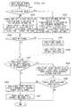
- step S01 it is determined whether or not the cruise control is being executed.
- the set/deceleration switch 16 is operated to be ON when the cruise control is not executed, an affirmative determination is made in the step S01.
- the release switch 17 is operated to be ON during execution of the cruise control, a negative determination is made in the step S01. In a case where the determination result in the step S01 is "NO", return is carried out.
- the target vehicle speed which becomes a control vehicle speed is determined. For example, if during running, the set/deceleration switch 16 is operated to be ON, the actual vehicle speed at that time is determined as the target vehicle speed. Also, if during cruise control execution, the return/acceleration switch 15 is operated to be ON, the target vehicle speed increases in accordance with the number of times of operation or operation duration. On the other hand, if during cruise control execution, the set/deceleration switch 16 is operated to be ON, the target vehicle speed decreases in accordance with the number of times of operation or in accordance with operation duration.
- step S03 the amount of increase and decrease of the throttle opening is calculated in accordance with the vehicle speed deviation ⁇ V of the actual vehicle speed which is detected by the vehicle speed sensor from the target vehicle speed determined in the step S02. Then, the target throttle opening is calculated based on the amount of increase and decrease.
- the target throttle opening which is calculated in the step S03 is a target throttle opening before being subjected to restriction (hereinafter referred to as a provisional target throttle opening).
- the throttle upper limit opening is determined. Then, a processing of restricting the provisional target throttle opening calculated in the step S03 is executed.
- step S200 for determination of the throttle upper limit opening which is performed in the next control period, it proceeds to step S200 and a mode determination processing is then executed. Then, after it proceeds to step S300, the target vehicle speed return processing is executed. Thereafter, return is performed.
- the throttle upper limit opening determination processing in the step S100, the mode determination processing in the step S200, and the target vehicle speed return processing in the step S300 are described sequentially.
- step S101 it is determined whether or not a fuel-efficient mode is selected. In a case where the determination result in the step S 101 is "NO", it proceeds to step S 102. Then, the throttle upper limit openings THh1, THh2, THh3, and THh4 of the CC eco-modes 1, 2, 3, and 4 at the time of the normal mode are set with reference to a throttle upper limit opening map for the normal mode (not shown) based on the following information (a) and (b). In addition, the magnitude relation of the throttle upper limit openings THh is set to be the relationship of THh1 ⁇ THh2 ⁇ THh3 ⁇ THh4.
- the throttle upper limit opening THh can be more finely set with respect to a variation in load by making the road gradient I a factor.
- step S101 determines whether the determination result in the step S101 is "YES" or "YES"
- the throttle upper limit openings THh1, THh2, THh3, and THh4 of the CC eco-modes 1, 2, 3, and 4 at the time of the fuel-efficient mode are set with reference to a throttle upper limit opening map for the fuel-efficient mode (not shown) based on the above-mentioned running information (a) and (b) at present time.
- a correlation between the throttle upper limit opening THh and the above-mentioned information (a) and (b) is the same as the case of the normal mode.
- the magnitude relation of the throttle upper limit openings THh is also set to be the relationship of THh1 ⁇ THh2 ⁇ THh3 ⁇ THh4 similarly to the normal mode.
- the driver can select any one of driving force control which is subjected to restriction of the throttle upper limit opening in the normal mode and driving force control which is subjected to restriction of the throttle upper limit opening in the fuel-efficient mode, by an operation of the fuel-efficient mode change-over switch 11.
- step S104 After proceeding from the step S 102 or S 103 to step S104, it is determined whether or not the present CC eco-mode is less than or equal to 1. In a case where the determination result in the step S104 is "YES" (CC eco-mode ⁇ 1), it proceeds to step S105. Then, the smaller opening out of the throttle upper limit opening THh1 of the CC eco-mode 1 and the provisional target throttle opening calculated in the step S03 is set to be the target throttle opening. On the other hand, in a case where the determination result in the step S104 is "NO" (CC eco-mode>1), after it proceeds to step S106, it is determined whether or not the present CC eco-mode is 2.
- step S 106 determines whether or not the present CC eco-mode is 3.
- step S108 determines whether or not the present CC eco-mode is 3.
- step S109 the smaller opening out of the throttle upper limit opening THh3 of the CC eco-mode 3 and the provisional target throttle opening calculated in the step S03 is set to be the target throttle opening.
- step S 110 determines whether the throttle opening is "NO" (CC eco-mode ⁇ 4). If the determination result in the step S 110 is "NO" (CC eco-mode ⁇ 4), it proceeds to step S 112. Then, after the throttle upper limit opening THh is set to be the fully open value, execution of this routine is temporarily ended. In other words, restriction is not provided to the throttle opening.
- step S201 it is determined whether or not the fuel-efficient mode is selected. In a case where the determination result in the step S201 is "NO", it proceeds to step S202. Then, transition determination threshold values (f) to (h) at the time of the normal mode are set with reference to the respective threshold value maps for the normal mode (not shown) based on the target vehicle speed which is set at present.
- setting of the vehicle speed deviation threshold value ⁇ Vcc is performed based on the target vehicle speed and the gradient of a road where the vehicle is running at present and on the other hand, the vehicle speed deviation threshold value ⁇ Vcc is set such that the larger the road gradient I becomes, the larger the vehicle speed deviation threshold value.
- the vehicle speed deviation threshold value ⁇ Vcc is set such that the larger the road gradient I becomes, the larger the vehicle speed deviation threshold value. Accordingly, control without making the driver feel a sense of discomfort can be realized.
- the cruise control makes the actual vehicle speed V be within the small vehicle speed deviation threshold value ⁇ Vcc .. For this reason, the target throttle opening becomes large. Accordingly, in this case, since a driving output becomes large, fuel efficiency deteriorates.
- the threshold value sign with attachment numerals means a determination threshold value of whether or not transition from the CC eco-mode of a grade that is indicated by the first numeral to the CC eco-mode of a grade that is indicated by the second numeral should be permitted.
- the vehicle speed deviation threshold value ⁇ Vcc12 is a vehicle speed deviation threshold value when determining whether or not transition from the CC eco-mode 1 to the CC eco-mode 2 should be permitted.
- the vehicle speed deviation threshold value ⁇ Vcc21 is a vehicle speed deviation threshold value when determining whether or not transition from the CC eco-mode 2 to the CC eco-mode 1 should be permitted.
- the acceleration threshold value Acc and the gradient threshold value Icc are also the same.
- a magnitude relation between the respective transition determination threshold values is set as follows.
- the transition determination threshold values of the CC eco-modes may be corrected based on actual fuel efficiency or the like, as necessary.
- step S201 determines whether the determination result in the step S201 is "YES" or "YES"
- step S203 each of the above-mentioned transition determination threshold value (f) to (h) at the time of the fuel-efficient mode is set with reference to each threshold value map for the fuel-efficient mode (not shown) based on the target vehicle speed which is set at present.
- a transition timer T12 is set to be the initial value. Then, it proceeds to step S211 (refer to FIG. 6 ).
- the transition timer T12 is a timer which measures a time (hereinafter referred to as a transition determination time) required to determine whether or not the transition from the CC eco-mode 1 to the CC eco-mode 2 should be permitted. This timer is a countdown timer which subtracts an elapsed time from an initial value.
- step S204 since the mode is the CC eco-mode 1, it proceeds to step S206. Then, it is determined whether or not the vehicle speed deviation ⁇ V of the current actual vehicle speed V from the target vehicle speed is greater than the determination threshold value (that is, the vehicle speed deviation threshold value ⁇ Vcc12) of whether or not the transition from the CC eco-mode 1 to the CC eco-mode 2 should be permitted set in the steps S202 and S203. In a case where the determination result in the step S206 is "NO" ( ⁇ V ⁇ Vcc12), since the CC eco-mode 1 should be maintained, it proceeds to the step S205. Then, the transition timer T12 is set to be the initial value.
- step S206 In a case where the determination result in the step S206 is "YES" ( ⁇ V> ⁇ Vcc12), it proceeds to step S207. Then, it is determined whether or not the road gradient and the acceleration satisfy conditions which permit the transition from the CC eco-mode 1 to the CC eco-mode 2.
- the road gradient I during the current running is larger than the determination threshold value (that is, the gradient threshold value Icc12) of whether or not the transition from the CC eco-mode 1 to the CC eco-mode 2 should be permitted set in the steps S202 and S203, and the present acceleration A is smaller than the determination threshold value (that is, the acceleration threshold value Acc12) of whether or not the transition from the CC eco-mode 1 to the CC eco-mode 2 should be permitted set in the steps S202 and S203.
- the determination threshold value that is, the gradient threshold value Icc12
- step S207 In a case where the determination result in the step S207 is "NO" (at least one of I>Icc12 and A ⁇ Acc12 is not established), since the CC eco-mode 1 should be maintained, it proceeds to step S208. Then, the transition timer T12 is set to be the initial value. On the other hand, in a case where the determination result in the step S207 is "YES" (I>Icc12 and A ⁇ Acc12), after it proceeds to step S209, it is determined whether or not the transition timer T12 is 0.
- the CC eco-mode is set to be 2. That is, the transition from the CC eco-mode 1 to the CC eco-mode 2 is performed. Then, it proceeds from the step S210 to the step S211.
- the determination result in the step S209 is "NO" (T12 ⁇ 0)
- step S211 it is determined whether or not the present mode is the CC eco-mode 2.
- the determination result in the step S211 is "NO" (CC eco-mode#2)
- the mode is any one of the CC eco-modes 1, 3, 4, and 5, it proceeds to step S212.
- step S21 since a transition timer T23 is set to be the initial value, it proceeds to step S213.
- step S224 (refer to FIG. 7 ).
- the transition timer T23 is a timer which measures a transition determination time from the CC eco-mode 2 to the CC eco-mode 3.
- the transition timer T21 is a timer which measures a transition determination time from the CC eco-mode 2 to the CC eco-mode 1. All of these timers are countdown timers which subtract an elapsed time from an initial value.
- step S211 determines whether or not the present vehicle speed deviation ⁇ V is larger than the determination threshold value (that is, the vehicle speed deviation threshold value ⁇ Vcc23) of whether or not the transition from the CC eco-mode 2 to the CC eco-mode 3 should be permitted set in the steps S202 and S203.
- the determination result in the step S214 is "NO" ( ⁇ V ⁇ Vcc23)
- the transition timer T23 is set to be the initial value, it proceeds to step S218.
- step S214 determines whether or not the road gradient and the acceleration satisfy conditions which permit the transition from the CC eco-mode 2 to the CC eco-mode 3.
- the road gradient I during the current running is larger than the determination threshold value (that is, the gradient threshold value Icc23) of whether or not the transition from the CC eco-mode 2 to the CC eco-mode 3 should be permitted set in the steps S202 and S203, and the present acceleration A is smaller than the determination threshold value (that is, the acceleration threshold value Acc23) of whether or not the transition from the CC eco-mode 2 to the CC eco-mode 3 should be permitted set in the steps S202 and S203.
- the determination threshold value that is, the gradient threshold value Icc23
- step S216 In a case where the determination result in the step S216 is "NO" (at least one of I>Icc23 and A ⁇ Acc23 is not established), since the transition to the CC eco-mode 3 should not be performed, it proceeds to step S217. Then, after the transition timer T23 is set to be the initial value, it proceeds to the step S218. On the other hand, in a case where the determination result in the step S216 is "YES" (I>Icc23 and A ⁇ Acc23), after it proceeds to step S219, it is determined whether or not the transition timer T23 is 0.
- step S218 it is determined whether or not the vehicle speed deviation, the road gradient, the throttle opening, and the acceleration satisfy conditions which permit the transition from the CC eco-mode 2 to the CC eco-mode 1. Specifically, it is determined whether or not the present vehicle speed deviation ⁇ V is smaller than the determination threshold value (that is, the vehicle speed deviation threshold value ⁇ Vcc21) of whether or not the transition from the CC eco-mode 2 to the CC eco-mode 1 should be permitted set in the steps S202 and S203, the road gradient I during the current running is smaller than the determination threshold value (that is, the gradient threshold value Icc21) of whether or not the transition from the CC eco-mode 2 to the CC eco-mode 1 should be permitted set in the steps S202 and S203, the present throttle opening TH is smaller than the throttle upper limit opening THh1 of the CC eco-mode 1 set in the steps S102 and S103 of the throttle upper limit opening determination processing, and the present acceleration A is larger than the determination threshold value (that is, the acceleration threshold value
- step S218 In a case where the determination result in the step S218 is "NO" (at least one of ⁇ V ⁇ Vcc21, I ⁇ Icc21, TH ⁇ THh1, and A>Acc21 is not established), since the transition to the CC eco-mode 1 should not be performed, it proceeds to step S221. Then, after the transition timer T21 is set to be the initial value, it proceeds to the step S224. On the other hand, in a case where the determination result in the step S218 is "YES" (all of ⁇ V ⁇ Vcc21, I ⁇ Icc21, TH ⁇ THh1, and A>Acc21 are established), after it proceeds to step S222, it is determined whether or not the transition timer T21 is 0.
- step S223 the CC eco-mode is set to be 1. That is, the transition from the CC eco-mode 2 to the CC eco-mode 1 is performed. Then, it proceeds from the step S223 to the step S224. On the other hand, in a case where the determination result in the step S222 is "NO" (T21 ⁇ 0), it proceeds to the step S224 without executing the processing of the step S223.
- the transition from the CC eco-mode 2 to the CC eco-mode 1 is performed.
- the transition to the CC eco-mode 1 is not performed. Accordingly, when the load instantaneously decreases due to unevenness or the like of the road surface, or the like, the complicated transition to another CC eco-mode can be prevented.
- step S224 it is determined whether or not the present mode is the CC eco-mode 3.
- the determination result in the step S224 is "NO" (CC eco-mode ⁇ 3)
- the mode is any one of the CC eco-modes 1, 2, 4, and 5, it proceeds to step S225.
- a transition timer T34 is set to be the initial value
- it proceeds to step S226.
- a transition timer T32 is set to be the initial value
- the transition timer T34 is a timer which measures a transition determination time from the CC eco-mode 3 to the CC eco-mode 4.
- the transition timer T32 is a timer which measures a transition determination time from the CC eco-mode 3 to the CC eco-mode 2. All of these timers are countdown timers which subtract an elapsed time from an initial value.
- step S224 since the mode is the CC eco-mode 3, it proceeds to step S227. Then, it is determined whether or not the present vehicle speed deviation ⁇ V is larger than the determination threshold value (that is, the vehicle speed deviation threshold value ⁇ Vcc34) of whether or not the transition from the CC eco-mode 3 to the CC eco-mode 4 should be permitted set in the steps S202 and S203. In a case where the determination result in the step S227 is "NO" ( ⁇ V ⁇ Vcc34), since the transition to the CC eco-mode 4 should not be performed, it proceeds to step S228. Then, after the transition timer T34 is set to be the initial value, it proceeds to step S231.
- the determination threshold value that is, the vehicle speed deviation threshold value ⁇ Vcc34
- step S227 determines whether or not the road gradient and the acceleration satisfy conditions which permit the transition from the CC eco-mode 3 to the CC eco-mode 4.
- the determination threshold value that is, the gradient threshold value Icc34
- the present acceleration A is smaller than the determination threshold value (that is, the acceleration threshold value Acc34) of whether or not the transition from the CC eco-mode 3 to the CC eco-mode 4 should be permitted set in the steps S202 and S203.
- step S229 In a case where the determination result in the step S229 is "NO" (at least one of I>Icc34 and A ⁇ Acc34 is not established), since the transition to the CC eco-mode 4 should not be performed, it proceeds to step S230. Then, after the transition timer T34 is set to be the initial value, it proceeds to the step S231. On the other hand, in a case where the determination result in the step S229 is "YES" (I>Icc34 and A ⁇ Acc34), after it proceeds to step S232, it is determined whether or not the transition timer T34 is 0.
- step S233 the CC eco-mode is set to be 4. That is, the transition from the CC eco-mode 3 to the CC eco-mode 4 is performed. Then, it proceeds from the step S233 to the step S231.
- the determination result in the step S232 is "NO" (T34 ⁇ 0)
- step S231 it is determined whether or not the vehicle speed deviation, the road gradient, the throttle opening, and the acceleration satisfy conditions which permit the transition from the CC eco-mode 3 to the CC eco-mode 2. Specifically, it is determined whether or not the present vehicle speed deviation ⁇ V is smaller than the determination threshold value (that is, the vehicle speed deviation threshold value ⁇ Vcc32) of whether or not the transition from the CC eco-mode 3 to the CC eco-mode 2 should be permitted set in the steps S202 and S203, the road gradient I during the current running is smaller than the determination threshold value (that is, the gradient threshold value Icc32) of whether or not the transition from the CC eco-mode 3 to the CC eco-mode 2 should be permitted set in the steps S202 and S203, the present throttle opening TH is smaller than the throttle upper limit opening THh2 of the CC eco-mode 2 set in the steps S102 and S103 of the throttle upper limit opening determination processing, and the present acceleration A is larger than the determination threshold value (that is, the acceleration threshold value
- step S231 In a case where the determination result in the step S231 is "NO" (at least one of ⁇ V ⁇ Vcc32, I ⁇ Icc32, TH ⁇ THh2, and A>Acc32 is not established), since the transition to the CC eco-mode 2 should not be performed, it proceeds to step S234. Then, after the transition timer T32 is set to be the initial value, it proceeds to the step S237. On the other hand, in a case where the determination result in the step S231 is "YES" (all of ⁇ V ⁇ Vec32, I ⁇ Icc32, TH ⁇ THh2, and A>Acc32 are established), after it proceeds to step S235, it is determined whether or not the transition timer T32 is 0.
- step S237 it is determined whether or not the present mode is the CC eco-mode 4.
- the determination result in the step S237 is "NO" (CC eco-mode ⁇ 4)
- the mode is any one of the CC eco-modes 1, 2, 3, and 5, it proceeds to step S238.
- a transition timer T45 is set to be the initial value
- it proceeds to step S239.
- a transition timer T43 is set to be the initial value
- the transition timer T45 is a timer which measures a transition determination time from the CC eco-mode 4 to the CC eco-mode 5.
- the transition timer T43 is a timer which measures a transition determination time from the CC eco-mode 4 to the CC eco-mode 3. All of these timers are countdown timers which subtract an elapsed time from an initial value.
- step S237 since the mode is the CC eco-mode 4, it proceeds to step S240. Then, it is determined whether or not the present vehicle speed deviation ⁇ V is larger than the determination threshold value (that is, the vehicle speed deviation threshold value ⁇ Vcc45) of whether or not the transition from the CC eco-mode 4 to the CC eco-mode 5 should be permitted set in the steps S202 and S203. In a case where the determination result in the step S240 is "NO" ( ⁇ V ⁇ Vcc45), since the transition to the CC eco-mode 5 should not be performed, it proceeds to step S241. Then, after the transition timer T45 is set to be the initial value, it proceeds to step S244.
- the determination threshold value that is, the vehicle speed deviation threshold value ⁇ Vcc45
- step S240 determines whether or not the road gradient and the acceleration satisfy conditions which permit the transition from the CC eco-mode 4 to the CC eco-mode 5.
- the determination threshold value that is, the gradient threshold value Icc45
- the present acceleration A is smaller than the determination threshold value (that is, the acceleration threshold value Acc45) of whether or not the transition from the CC eco-mode 4 to the CC eco-mode 5 should be permitted set in the steps S202 and S203.
- step S242 In a case where the determination result in the step S242 is "NO" (at least one of I>Icc45 and A ⁇ Acc45 is not established), since the transition to the CC eco-mode 5 should not be performed, it proceeds to step S243. Then, after the transition timer T45 is set to be the initial value, it proceeds to the step S244. On the other hand, in a case where the determination result in the step S242 is "YES" (I>Icc45 and A ⁇ Acc45), after it proceeds to step S245, it is determined whether or not the transition timer T45 is 0.
- step S244 it is determined whether or not the vehicle speed deviation, the road gradient, the throttle opening, and the acceleration satisfy conditions which permit the transition from the CC eco-mode 4 to the CC eco-mode 3. Specifically, it is determined whether or not the present vehicle speed deviation ⁇ V is smaller than the determination threshold value (that is, the vehicle speed deviation threshold value ⁇ Vcc43) of whether or not the transition from the CC eco-mode 4 to the CC eco-mode 3 should be permitted set in the steps S202 and S203, the road gradient I during the current running is smaller than the determination threshold value (that is, the gradient threshold value Icc43) of whether or not the transition from the CC eco-mode 4 to the CC eco-mode 3 should be permitted set in the steps S202 and S203, the present throttle opening TH is smaller than the throttle upper limit opening THh3 of the CC eco-mode 3 set in the steps S102 and S103 of the throttle upper limit opening determination processing, and the present acceleration A is larger than the determination threshold value (that is, the acceleration threshold value
- step S244 determines whether or not the transition timer T43 is 0.
- step S250 it is determined whether or not the present mode is the CC eco-mode 5.
- the determination result in the step S250 is "NO" (CC eco-mode ⁇ 5)
- the mode is any one of the CC eco-modes 1, 2, 3, and 4, it proceeds to step S251.
- a transition timer T54 is set to be the initial value, and execution of this routine is temporarily ended.
- the transition timer T54 is a timer which measures a transition determination time from the CC eco-mode 5 to the CC eco-mode 4. This timer is a countdown timer which subtracts an elapsed time from an initial value.
- step S250 since the mode is the CC eco-mode 5, it proceeds to step S252. Then, it is determined whether or not the vehicle speed deviation, the road gradient, the throttle opening, and the acceleration satisfy conditions which permit the transition from the CC eco-mode 5 to the CC eco-mode 4.
- the present vehicle speed deviation ⁇ V is smaller than the determination threshold value (that is, the vehicle speed deviation threshold value ⁇ Vcc54) of whether or not the transition from the CC eco-mode 5 to the CC eco-mode 4 should be permitted set in the steps S202 and S203
- the road gradient I during the current running is smaller than the determination threshold value (that is, the gradient threshold value Icc54) of whether or not the transition from the CC eco-mode 5 to the CC eco-mode 4 should be permitted set in the steps S202 and S203
- the present throttle opening TH is smaller than the throttle upper limit opening THh4 of the CC eco-mode 4 set in the steps S102 and S103 of the throttle upper limit opening determination processing
- the present acceleration A is larger than the determination threshold value (that is, the acceleration threshold value Acc54) of whether or not the transition from the CC eco-mode 5 to the CC eco-mode 4 should be permitted set in the steps S202 and S203.
- step S252 In a case where the determination result in the step S252 is "NO" (at least one of ⁇ V ⁇ Vcc54, I ⁇ Icc54, TH ⁇ THh4, and A>Acc54 is not established), since the transition to the CC eco-mode 4 should not be performed, it proceeds to step S253. Then, after the transition timer T54 is set to be the initial value, execution of this routine is temporarily ended. On the other hand, in a case where the determination result in the step S252 is "YES" (all of ⁇ V ⁇ Vcc54, I ⁇ Icc54, TH ⁇ THh4, and A>Acc54 are established), after it proceeds to step S254, it is determined whether or not the transition timer T54 is 0.
- the vehicle speed deviation threshold value ⁇ Vcc is set corresponding to the magnitude of the throttle upper limit opening THh.
- the vehicle speed deviation threshold value ⁇ Vcc is set such that the larger the throttle upper limit opening THh, the larger the vehicle speed deviation threshold value.
- a vehicle speed deviation condition in which the vehicle speed deviation ⁇ V is larger than the vehicle speed deviation threshold value ⁇ Vcc
- a gradient condition in which the road gradient I is larger than the gradient threshold value Icc
- step S301 it is determined whether or not the fuel-efficient mode is selected. In a case where the determination result in the step S301 is "NO", it proceeds to step S302. Then, after a transition rate from the provisional target vehicle speed to the original target vehicle speed, which is applied when switching the grade of the CC eco-mode at the time of the normal mode, is calculated with reference to a transition rate map for the normal mode (not shown) or by a calculating formula, based on the following information (j) to (o), this is set.
- this transition rate is a restriction value of a variation (hereinafter referred to as a variation restriction value) per unit time of the provisional target vehicle speed.
- the transition rate (the variation restriction value) is set such that the larger the actual vehicle speed V, the smaller the value of the transition rate (the variation restriction value). Then, the transition rate (the variation restriction value) is set such that the larger the vehicle speed deviation ⁇ V, the larger the value of the transition rate (the variation restriction value). This is because even on a road having the same load variation, running resistance to the vehicle increases in proportion to the square of the actual vehicle speed. Accordingly, fuel consumption at the time of the target vehicle speed return during high speed running is suppressed by setting the transition rate such that the larger the actual vehicle speed V, the smaller the transition rate. Also, by setting the variation restriction value based on the vehicle speed deviation ⁇ V, the target vehicle speed return processing can be performed without making the driver feel a sense of discomfort.
- the transition rate (the variation restriction value) is set to be small, and on the other hand, in a case where the road gradient I is a downhill gradient, the transition rate (the variation restriction value) is set to be large. This is because the transition to the original target vehicle speed can be slowly carried out by setting the transition rate (the variation restriction value) to be small at the time of a rising gradient. For this reason, since the driving force output of the engine on an uphill road can be kept low, the effect of improvement in fuel efficiency is obtained. On the other hand, on a downhill road, naturally, the driving force output of the engine is small.
- the transition rate (the variation restriction value) to be large at the time of a downhill gradient
- fuel efficiency at the time of transition can be improved.
- the transition rate (the variation restriction value) is large at the time of a downhill gradient, it is possible to not make the driver feel a sense of discomfort.
- the transition rate (the variation restriction value) may be corrected based on the elapsed time t and the vehicle speed deviation ⁇ V. For example, in a case where the vehicle speed deviation ⁇ V does not become small even though the elapsed time t has increased, the transition rate (the variation restriction value) is corrected to become larger than usual. Accordingly, convergence of the actual vehicle speed to the target vehicle speed can be accelerated. Also, in a case where actual acceleration is small compared with a target vehicle speed transition rate, a difference between the vehicle speed and the target vehicle speed during return becomes large.
- the transition rate is set to be small. Also, since the grade of the CC eco-mode before and after switching has a correlation with the vehicle speed deviation ⁇ V and the road gradient I, the grade of the CC eco-mode before and after switching can also be used as the alternative values of ⁇ V and I.
- step S301 determines whether the provisional target vehicle speed is "YES" or "YES"
- step S303 a transition rate map for the fuel-efficient mode (not shown) or by a calculating formula, based on the above-mentioned information (j) to (o)
- step S304 After proceeding from the steps S302 and S303 to step S304, it is determined whether or not mode switching has occurred.
- mode switching between the normal mode and the fuel-efficient mode, grade switching of the CC eco-mode at the time of the normal mode, and grade switching of the CC eco-mode at the time of the fuel-effcient mode are included.
- the initial value of the provisional target vehicle speed is set.
- the current actual vehicle speed V is set as the initial value of the provisional target vehicle speed.
- this may be set.
- step S305 proceeds from the step S305 to step S306.
- step S307 After time measurement by a target vehicle speed return timer is started, it proceeds to step S307.
- the target vehicle speed return timer is a timer which measures the elapsed time from execution of the mode switching. This timer is a count-up timer which counts up starting from 0.
- the determination result in the step S304 is "NO" (no mode switching)
- step S307 it is determined whether or not the provisional target throttle opening is being calculated by using the provisional target vehicle speed in place of the original target vehicle speed and whether or not there is no driver's intention to accelerate.
- a case where the initial value of the provisional target vehicle speed has been set in the step S305 is also included in a case where the provisional target throttle opening is calculated using the provisional target vehicle speed.
- the determination of the driver's intention to accelerate it is determined that there is an intention to accelerate, for example, in a case where there is an operation to increase the vehicle speed by the driver stepping on an accelerator pedal, or the like.
- step S307 In a case where the determination result in the step S307 is "YES", since the provisional target throttle opening is being calculated using the provisional target vehicle speed and the driver does not have intention to accelerate, it proceeds to step S308. Then, the provisional target vehicle speed is gradually returned to the original target vehicle speed in accordance with the transition rate set in the steps S302 and S303. That is, after the transition rate is set in the steps S302 and S303, the provisional target vehicle speed is made to gradually approximate the original target vehicle speed by restricting the variation per unit time of the provisional target vehicle speed based on this transition rate.
- the provisional target vehicle speed is made to gradually approximate the original target vehicle speed, as shown in an M point in FIG 11 , in a case where the actual vehicle speed V has become greater than the provisional target vehicle speed by a value greater than or equal to a predetermined value, the value of the current actual vehicle speed V is set as the provisional target vehicle speed.
- the provisional target vehicle speed may be increased to be more than or equal to the transition rate (the variation restriction value).
- FIG. 12 shows a comparative example and also shows a case where control to maintain the transition rate (the variation restriction value) of the provisional target vehicle speed is continued even in a case where the actual vehicle speed V has exceeded the provisional target vehicle speed.
- the original purpose of the target vehicle speed return process is to converge the actual vehicle speed V with the original target vehicle speed. If the control to maintain the transition rate (the variation restriction value) is continued regardless of the actual vehicle speed V exceeding the provisional target vehicle speed and then approaching the original target speed, the actual vehicle speed V is drawn to the provisional target vehicle speed, thereby being reduced. For this reason, convergence to the original target speed becomes slow.
- step S309 it is determined whether or not the current actual vehicle speed V is greater than or equal to the original target vehicle speed.
- the determination result in the step S309 is "NO" (the actual vehicle speed ⁇ the original target vehicle speed)
- execution of this routine is temporarily ended.
- the determination result in the step S307 is "NO”
- a case where the determination result in the step S309 is "YES” it proceeds to step S310.
- the case where the determination result in the step S307 is "NO” is a case where calculation of the target throttle opening with application of the provisional target vehicle speed has not been performed or the driver has an intention to accelerate.
- the provisional target vehicle speed is immediately returned to the original target vehicle speed. This is for returning the throttle opening control to the original state without causing a sense of discomfort to the driver, by immediately returning the provisional target vehicle speed to the original target vehicle speed when an operation to increase the actual vehicle speed by intervention of an accelerator pedal, or the like has occurred,
- the provisional target vehicle speed is set and on the other hand, the vehicle speed deviation ⁇ V from the actual vehicle speed V is calculated by using the provisional target vehicle speed in place of the original target vehicle speed. Then, since the target throttle opening is calculated based on this vehicle speed deviation, a rapid increase in the throttle opening (that is, a rapid increase in the driving force output) accompanying the switching of the throttle upper limit opening can be prevented. Accordingly, the fuel efficiency can be improved. Furthermore, since the provisional target vehicle speed is made to gradually approximate the original target vehicle speed, recovery control which returns the lowered vehicle speed to the original target vehicle speed can be carried out without sudden acceleration. Accordingly, return to an original control state can be performed with the output of a small driving force.
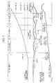
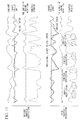
- FIG. 13 shows time charts of the throttle opening or the like at the time of the cruise control running.
- the lower half of this drawing shows a case where the throttle opening control (driving force control) is performed with a plurality of throttle upper limit openings set at the time of the cruise control running, similarly to the above-described embodiment.
- the upper half of this drawing shows a case where the throttle opening control is performed without setting the throttle upper limit opening. From this drawing, it can be seen that in the case of the embodiment, although variations in the vehicle speed becomes greater than the case of the comparative example, variations in the throttle opening can be suppressed. Therefore, in the embodiment, fuel efficiency becomes superior to the comparative example.
- the technical scope of the present invention is not limited only to the above-described embodiment, but includes various changes applied to the above-described embodiment within the scope that does not depart from the purport of the present invention. That is, the specific processing, configuration, or the like mentioned in this embodiment is only one example and appropriate changes are possible.
- the target driving force which is calculated by the target driving force calculating means is set to be the target throttle opening.
- the target driving force may be set to be an accelerator pedal opening or torque.
- the running control device for a vehicle in the cruise control, restriction of a driving force can be performed. Accordingly, since the driving force of the engine can be accurately restricted regardless of the vehicle speed or the state of a driving force transmission device, fuel efficiency in the cruise control can be improved.
Applications Claiming Priority (2)
| Application Number | Priority Date | Filing Date | Title |
|---|---|---|---|
| JP2008309918A JP4806704B2 (ja) | 2008-12-04 | 2008-12-04 | 車両用走行制御装置 |
| PCT/JP2009/006039 WO2010064363A1 (ja) | 2008-12-04 | 2009-11-12 | 車両用走行制御装置 |
Publications (3)
| Publication Number | Publication Date |
|---|---|
| EP2364892A1 true EP2364892A1 (de) | 2011-09-14 |
| EP2364892A4 EP2364892A4 (de) | 2013-05-15 |
| EP2364892B1 EP2364892B1 (de) | 2014-12-31 |
Family
ID=42233022
Family Applications (1)
| Application Number | Title | Priority Date | Filing Date |
|---|---|---|---|
| EP09830134.4A Not-in-force EP2364892B1 (de) | 2008-12-04 | 2009-11-12 | Fahrzeuglaufsteuerung |
Country Status (6)
| Country | Link |
|---|---|
| US (1) | US8463522B2 (de) |
| EP (1) | EP2364892B1 (de) |
| JP (1) | JP4806704B2 (de) |
| CN (1) | CN102216140B (de) |
| CA (1) | CA2744984C (de) |
| WO (1) | WO2010064363A1 (de) |
Cited By (2)
| Publication number | Priority date | Publication date | Assignee | Title |
|---|---|---|---|---|
| WO2013139625A1 (de) * | 2012-03-22 | 2013-09-26 | Ford Global Technologies, Llc | Verfahren und vorrichtung zum regeln der geschwindigkeit eines kraftfahrzeugs |
| AT519888A1 (de) * | 2017-04-25 | 2018-11-15 | Avl List Gmbh | Verfahren zum betreiben eines fahrzeuges |
Families Citing this family (18)
| Publication number | Priority date | Publication date | Assignee | Title |
|---|---|---|---|---|
| BRPI0925298B1 (pt) * | 2009-07-02 | 2021-03-30 | Volvo Lastvagnar Ab | Método e sistema para controle de um controle de cruzeiro de veículo |
| WO2013095242A1 (en) * | 2011-12-22 | 2013-06-27 | Scania Cv Ab | Method and module for determining of at least one reference value |
| WO2013095232A1 (en) * | 2011-12-22 | 2013-06-27 | Scania Cv Ab | Method and module for controlling a vehicle's speed based on rules and/or costs |
| JP2014009987A (ja) * | 2012-06-28 | 2014-01-20 | Micware Co Ltd | 車載装置、運転支援方法、およびプログラム |
| GB2505022B (en) * | 2012-08-16 | 2015-01-14 | Jaguar Land Rover Ltd | Speed control system and method for operating the same |
| KR101467377B1 (ko) * | 2013-08-28 | 2014-12-10 | (주)로드피아 | 차량의 크루즈 컨트롤 방법 및 그 장치 |
| GB2519533B (en) * | 2013-10-23 | 2018-04-04 | Jaguar Land Rover Ltd | Vehicle speed control system |
| US10543839B2 (en) * | 2014-09-24 | 2020-01-28 | Shem, Llc | Low speed cruise control for a vehicle |
| US10124784B2 (en) * | 2015-04-13 | 2018-11-13 | Ford Global Technologies, Llc | Method and system for controlling shifting of a vehicle in cruise control |
| MY183379A (en) * | 2015-11-09 | 2021-02-18 | Nissan Motor | Braking/driving force control method and braking/driving force control device |
| CN106240364B (zh) * | 2016-07-28 | 2019-03-26 | 大连大学 | 一种自动档车辆行驶情景模拟系统及控制方法 |
| CN106671776B (zh) * | 2016-12-09 | 2019-03-22 | 重庆长安汽车股份有限公司 | 基于驾驶员操作的车辆行驶速度控制系统及方法 |
| US10787174B2 (en) | 2017-10-13 | 2020-09-29 | Toyota Motor Engineering & Manufacutring North America, Inc. | Automatic vehicle driving mode system |
| KR20190072311A (ko) * | 2017-12-15 | 2019-06-25 | 현대자동차주식회사 | 차량의 속도 제한 장치 및 그 방법 |
| JP7070309B2 (ja) * | 2018-10-10 | 2022-05-18 | トヨタ自動車株式会社 | 車両制御装置 |
| CN111703423B (zh) * | 2019-03-18 | 2022-05-06 | 毫末智行科技有限公司 | 自动驾驶车辆的纵向控制安全监测方法及系统 |
| CN112896138B (zh) * | 2019-11-19 | 2022-11-29 | 北京车和家信息技术有限公司 | 车辆限速方法、装置及车辆 |
| CN116368044A (zh) | 2020-11-06 | 2023-06-30 | 日产自动车株式会社 | 车辆控制方法以及车辆控制装置 |
Citations (5)
| Publication number | Priority date | Publication date | Assignee | Title |
|---|---|---|---|---|
| US20040084237A1 (en) * | 2002-05-30 | 2004-05-06 | Petrie Alfred E. | Vehicle cruise control system |
| US20050000479A1 (en) * | 2003-07-04 | 2005-01-06 | Honda Motor Co., Ltd. | Control apparatus for hybrid vehicle |
| DE102005017965A1 (de) * | 2005-04-19 | 2006-10-26 | Cristobal Guzman | Über den Kraftstoffverbrauch gesteuertes Kraftfahrzeug |
| DE102005045891B3 (de) * | 2005-09-26 | 2007-02-15 | Siemens Ag | Verfahren zur Kraftstoffverbrauchsreduktion einer Brennkraftmaschine |
| US20080076622A1 (en) * | 2006-09-27 | 2008-03-27 | Jungheinrich Aktiengesellschaft | Apparatus for controlling a hybrid drive system for a motor vehicle, an industrial truck in particular |
Family Cites Families (7)
| Publication number | Priority date | Publication date | Assignee | Title |
|---|---|---|---|---|
| JPH1148823A (ja) * | 1997-08-04 | 1999-02-23 | Mitsubishi Motors Corp | 車両用定速走行装置 |
| JP2003291687A (ja) * | 2002-04-04 | 2003-10-15 | Mitsubishi Fuso Truck & Bus Corp | 車両の速度制御装置 |
| JP2003343305A (ja) | 2002-05-30 | 2003-12-03 | Toyota Motor Corp | クルーズコントロール装置 |
| JP3613264B2 (ja) * | 2002-06-18 | 2005-01-26 | 日産自動車株式会社 | 車両用運転操作補助装置 |
| JP4554551B2 (ja) | 2006-04-28 | 2010-09-29 | 本田技研工業株式会社 | 車両用走行制御装置 |
| JP2008095635A (ja) * | 2006-10-13 | 2008-04-24 | Toyota Motor Corp | 駆動力制御装置 |
| JP2008309918A (ja) | 2007-06-13 | 2008-12-25 | Panasonic Corp | プラズマディスプレイ装置およびプラズマディスプレイパネルの駆動方法 |
-
2008
- 2008-12-04 JP JP2008309918A patent/JP4806704B2/ja not_active Expired - Fee Related
-
2009
- 2009-11-12 EP EP09830134.4A patent/EP2364892B1/de not_active Not-in-force
- 2009-11-12 CA CA2744984A patent/CA2744984C/en not_active Expired - Fee Related
- 2009-11-12 US US13/131,915 patent/US8463522B2/en active Active
- 2009-11-12 WO PCT/JP2009/006039 patent/WO2010064363A1/ja active Application Filing
- 2009-11-12 CN CN200980145888.5A patent/CN102216140B/zh active Active
Patent Citations (5)
| Publication number | Priority date | Publication date | Assignee | Title |
|---|---|---|---|---|
| US20040084237A1 (en) * | 2002-05-30 | 2004-05-06 | Petrie Alfred E. | Vehicle cruise control system |
| US20050000479A1 (en) * | 2003-07-04 | 2005-01-06 | Honda Motor Co., Ltd. | Control apparatus for hybrid vehicle |
| DE102005017965A1 (de) * | 2005-04-19 | 2006-10-26 | Cristobal Guzman | Über den Kraftstoffverbrauch gesteuertes Kraftfahrzeug |
| DE102005045891B3 (de) * | 2005-09-26 | 2007-02-15 | Siemens Ag | Verfahren zur Kraftstoffverbrauchsreduktion einer Brennkraftmaschine |
| US20080076622A1 (en) * | 2006-09-27 | 2008-03-27 | Jungheinrich Aktiengesellschaft | Apparatus for controlling a hybrid drive system for a motor vehicle, an industrial truck in particular |
Non-Patent Citations (1)
| Title |
|---|
| See also references of WO2010064363A1 * |
Cited By (3)
| Publication number | Priority date | Publication date | Assignee | Title |
|---|---|---|---|---|
| WO2013139625A1 (de) * | 2012-03-22 | 2013-09-26 | Ford Global Technologies, Llc | Verfahren und vorrichtung zum regeln der geschwindigkeit eines kraftfahrzeugs |
| AT519888A1 (de) * | 2017-04-25 | 2018-11-15 | Avl List Gmbh | Verfahren zum betreiben eines fahrzeuges |
| AT519888B1 (de) * | 2017-04-25 | 2019-02-15 | Avl List Gmbh | Verfahren zum betreiben eines fahrzeuges |
Also Published As
| Publication number | Publication date |
|---|---|
| CA2744984C (en) | 2013-07-09 |
| US8463522B2 (en) | 2013-06-11 |
| JP2010132132A (ja) | 2010-06-17 |
| CN102216140B (zh) | 2014-03-19 |
| EP2364892B1 (de) | 2014-12-31 |
| CN102216140A (zh) | 2011-10-12 |
| CA2744984A1 (en) | 2010-06-10 |
| WO2010064363A1 (ja) | 2010-06-10 |
| EP2364892A4 (de) | 2013-05-15 |
| US20110246042A1 (en) | 2011-10-06 |
| JP4806704B2 (ja) | 2011-11-02 |
Similar Documents
| Publication | Publication Date | Title |
|---|---|---|
| EP2364892B1 (de) | Fahrzeuglaufsteuerung | |
| EP2054600B1 (de) | Vorrichtung zur unterstützung einer verbesserten brennstoffökonomie und verfahren zur unterstützung einer verbesserten brennstoffökonomie | |
| KR101459451B1 (ko) | 운전패턴 학습을 통한 차량 능동제어 방법 및 시스템 | |
| KR100887797B1 (ko) | 하이브리드 차량의 오토크루즈 주행 제어 방법 | |
| JP3767244B2 (ja) | 車両の駆動力制御装置 | |
| US11118678B2 (en) | Vehicle control device and vehicle control method | |
| EP2781721A1 (de) | Fahrzeugsteuerungsvorrichtung, fahrzeug und fahrzeugsteuerungsverfahren | |
| JP2007038933A (ja) | 車両走行制御装置 | |
| US7016803B2 (en) | Acceleration control device | |
| US11654777B2 (en) | Electric vehicle | |
| EP2754925A1 (de) | Steuervorrichtung für ein kontinuierlich variables getriebe | |
| JP2012002194A (ja) | 車両制御装置 | |
| JP4178891B2 (ja) | 車両の駆動力制御方法およびこの方法を用いた駆動力制御装置 | |
| JPH11182274A (ja) | スロットル制御装置 | |
| US10982756B2 (en) | Vehicle control device | |
| CN108374887B (zh) | 车辆的控制装置 | |
| KR100340256B1 (ko) | 무단변속기의 변속비제어장치 | |
| CN104340066B (zh) | 车辆定速巡航和节油方法 | |
| CN110906001B (zh) | 车辆的控制装置 | |
| JP4120532B2 (ja) | 自動変速機の変速制御装置 | |
| KR20220004853A (ko) | 수동 변속기 차량의 크루즈 컨트롤 제어 방법 및 이에 적용되는 크루즈 컨트롤 제어 장치 | |
| JP2004197647A (ja) | 推奨と実行のアクセル開度対比により制御される自動車 | |
| CN108603452B (zh) | 用于运行驱动装置的方法和设备以及驱动装置 | |
| JP4480752B2 (ja) | 車両エンジンの制御装置 | |
| JP5225251B2 (ja) | 車両駆動力制御装置 |
Legal Events
| Date | Code | Title | Description |
|---|---|---|---|
| PUAI | Public reference made under article 153(3) epc to a published international application that has entered the european phase |
Free format text: ORIGINAL CODE: 0009012 |
|
| 17P | Request for examination filed |
Effective date: 20110607 |
|
| AK | Designated contracting states |
Kind code of ref document: A1 Designated state(s): AT BE BG CH CY CZ DE DK EE ES FI FR GB GR HR HU IE IS IT LI LT LU LV MC MK MT NL NO PL PT RO SE SI SK SM TR |
|
| DAX | Request for extension of the european patent (deleted) | ||
| A4 | Supplementary search report drawn up and despatched |
Effective date: 20130417 |
|
| RIC1 | Information provided on ipc code assigned before grant |
Ipc: F02D 29/02 20060101ALI20130411BHEP Ipc: B60K 31/00 20060101ALI20130411BHEP Ipc: B60W 30/14 20060101AFI20130411BHEP |
|
| 17Q | First examination report despatched |
Effective date: 20130507 |
|
| GRAP | Despatch of communication of intention to grant a patent |
Free format text: ORIGINAL CODE: EPIDOSNIGR1 |
|
| INTG | Intention to grant announced |
Effective date: 20140715 |
|
| GRAS | Grant fee paid |
Free format text: ORIGINAL CODE: EPIDOSNIGR3 |
|
| GRAA | (expected) grant |
Free format text: ORIGINAL CODE: 0009210 |
|
| AK | Designated contracting states |
Kind code of ref document: B1 Designated state(s): AT BE BG CH CY CZ DE DK EE ES FI FR GB GR HR HU IE IS IT LI LT LU LV MC MK MT NL NO PL PT RO SE SI SK SM TR |
|
| REG | Reference to a national code |
Ref country code: CH Ref legal event code: EP Ref country code: GB Ref legal event code: FG4D |
|
| REG | Reference to a national code |
Ref country code: IE Ref legal event code: FG4D |
|
| REG | Reference to a national code |
Ref country code: AT Ref legal event code: REF Ref document number: 704172 Country of ref document: AT Kind code of ref document: T Effective date: 20150215 |
|
| REG | Reference to a national code |
Ref country code: DE Ref legal event code: R096 Ref document number: 602009028753 Country of ref document: DE Effective date: 20150219 |
|
| PG25 | Lapsed in a contracting state [announced via postgrant information from national office to epo] |
Ref country code: LT Free format text: LAPSE BECAUSE OF FAILURE TO SUBMIT A TRANSLATION OF THE DESCRIPTION OR TO PAY THE FEE WITHIN THE PRESCRIBED TIME-LIMIT Effective date: 20141231 Ref country code: FI Free format text: LAPSE BECAUSE OF FAILURE TO SUBMIT A TRANSLATION OF THE DESCRIPTION OR TO PAY THE FEE WITHIN THE PRESCRIBED TIME-LIMIT Effective date: 20141231 Ref country code: NO Free format text: LAPSE BECAUSE OF FAILURE TO SUBMIT A TRANSLATION OF THE DESCRIPTION OR TO PAY THE FEE WITHIN THE PRESCRIBED TIME-LIMIT Effective date: 20150331 |
|
| REG | Reference to a national code |
Ref country code: NL Ref legal event code: VDEP Effective date: 20141231 |
|
| REG | Reference to a national code |
Ref country code: LT Ref legal event code: MG4D |
|
| PG25 | Lapsed in a contracting state [announced via postgrant information from national office to epo] |
Ref country code: GR Free format text: LAPSE BECAUSE OF FAILURE TO SUBMIT A TRANSLATION OF THE DESCRIPTION OR TO PAY THE FEE WITHIN THE PRESCRIBED TIME-LIMIT Effective date: 20150401 Ref country code: HR Free format text: LAPSE BECAUSE OF FAILURE TO SUBMIT A TRANSLATION OF THE DESCRIPTION OR TO PAY THE FEE WITHIN THE PRESCRIBED TIME-LIMIT Effective date: 20141231 Ref country code: LV Free format text: LAPSE BECAUSE OF FAILURE TO SUBMIT A TRANSLATION OF THE DESCRIPTION OR TO PAY THE FEE WITHIN THE PRESCRIBED TIME-LIMIT Effective date: 20141231 Ref country code: SE Free format text: LAPSE BECAUSE OF FAILURE TO SUBMIT A TRANSLATION OF THE DESCRIPTION OR TO PAY THE FEE WITHIN THE PRESCRIBED TIME-LIMIT Effective date: 20141231 |
|
| REG | Reference to a national code |
Ref country code: AT Ref legal event code: MK05 Ref document number: 704172 Country of ref document: AT Kind code of ref document: T Effective date: 20141231 |
|
| PG25 | Lapsed in a contracting state [announced via postgrant information from national office to epo] |
Ref country code: NL Free format text: LAPSE BECAUSE OF FAILURE TO SUBMIT A TRANSLATION OF THE DESCRIPTION OR TO PAY THE FEE WITHIN THE PRESCRIBED TIME-LIMIT Effective date: 20141231 |
|
| PG25 | Lapsed in a contracting state [announced via postgrant information from national office to epo] |
Ref country code: ES Free format text: LAPSE BECAUSE OF FAILURE TO SUBMIT A TRANSLATION OF THE DESCRIPTION OR TO PAY THE FEE WITHIN THE PRESCRIBED TIME-LIMIT Effective date: 20141231 Ref country code: SK Free format text: LAPSE BECAUSE OF FAILURE TO SUBMIT A TRANSLATION OF THE DESCRIPTION OR TO PAY THE FEE WITHIN THE PRESCRIBED TIME-LIMIT Effective date: 20141231 Ref country code: CZ Free format text: LAPSE BECAUSE OF FAILURE TO SUBMIT A TRANSLATION OF THE DESCRIPTION OR TO PAY THE FEE WITHIN THE PRESCRIBED TIME-LIMIT Effective date: 20141231 Ref country code: RO Free format text: LAPSE BECAUSE OF FAILURE TO SUBMIT A TRANSLATION OF THE DESCRIPTION OR TO PAY THE FEE WITHIN THE PRESCRIBED TIME-LIMIT Effective date: 20141231 |
|
| PG25 | Lapsed in a contracting state [announced via postgrant information from national office to epo] |
Ref country code: PL Free format text: LAPSE BECAUSE OF FAILURE TO SUBMIT A TRANSLATION OF THE DESCRIPTION OR TO PAY THE FEE WITHIN THE PRESCRIBED TIME-LIMIT Effective date: 20141231 Ref country code: AT Free format text: LAPSE BECAUSE OF FAILURE TO SUBMIT A TRANSLATION OF THE DESCRIPTION OR TO PAY THE FEE WITHIN THE PRESCRIBED TIME-LIMIT Effective date: 20141231 Ref country code: IS Free format text: LAPSE BECAUSE OF FAILURE TO SUBMIT A TRANSLATION OF THE DESCRIPTION OR TO PAY THE FEE WITHIN THE PRESCRIBED TIME-LIMIT Effective date: 20150430 |
|
| REG | Reference to a national code |
Ref country code: DE Ref legal event code: R097 Ref document number: 602009028753 Country of ref document: DE |
|
| PG25 | Lapsed in a contracting state [announced via postgrant information from national office to epo] |
Ref country code: DK Free format text: LAPSE BECAUSE OF FAILURE TO SUBMIT A TRANSLATION OF THE DESCRIPTION OR TO PAY THE FEE WITHIN THE PRESCRIBED TIME-LIMIT Effective date: 20141231 Ref country code: EE Free format text: LAPSE BECAUSE OF FAILURE TO SUBMIT A TRANSLATION OF THE DESCRIPTION OR TO PAY THE FEE WITHIN THE PRESCRIBED TIME-LIMIT Effective date: 20141231 |
|
| PLBE | No opposition filed within time limit |
Free format text: ORIGINAL CODE: 0009261 |
|
| STAA | Information on the status of an ep patent application or granted ep patent |
Free format text: STATUS: NO OPPOSITION FILED WITHIN TIME LIMIT |
|
| REG | Reference to a national code |
Ref country code: FR Ref legal event code: PLFP Year of fee payment: 7 |
|
| 26N | No opposition filed |
Effective date: 20151001 |
|
| PG25 | Lapsed in a contracting state [announced via postgrant information from national office to epo] |
Ref country code: IT Free format text: LAPSE BECAUSE OF FAILURE TO SUBMIT A TRANSLATION OF THE DESCRIPTION OR TO PAY THE FEE WITHIN THE PRESCRIBED TIME-LIMIT Effective date: 20141231 |
|
| PGFP | Annual fee paid to national office [announced via postgrant information from national office to epo] |
Ref country code: DE Payment date: 20150915 Year of fee payment: 7 Ref country code: GB Payment date: 20151118 Year of fee payment: 7 |
|
| PG25 | Lapsed in a contracting state [announced via postgrant information from national office to epo] |
Ref country code: SI Free format text: LAPSE BECAUSE OF FAILURE TO SUBMIT A TRANSLATION OF THE DESCRIPTION OR TO PAY THE FEE WITHIN THE PRESCRIBED TIME-LIMIT Effective date: 20141231 |
|
| PGFP | Annual fee paid to national office [announced via postgrant information from national office to epo] |
Ref country code: FR Payment date: 20151119 Year of fee payment: 7 |
|
| PG25 | Lapsed in a contracting state [announced via postgrant information from national office to epo] |
Ref country code: BE Free format text: LAPSE BECAUSE OF FAILURE TO SUBMIT A TRANSLATION OF THE DESCRIPTION OR TO PAY THE FEE WITHIN THE PRESCRIBED TIME-LIMIT Effective date: 20141231 |
|
| PG25 | Lapsed in a contracting state [announced via postgrant information from national office to epo] |
Ref country code: MC Free format text: LAPSE BECAUSE OF FAILURE TO SUBMIT A TRANSLATION OF THE DESCRIPTION OR TO PAY THE FEE WITHIN THE PRESCRIBED TIME-LIMIT Effective date: 20141231 Ref country code: LU Free format text: LAPSE BECAUSE OF FAILURE TO SUBMIT A TRANSLATION OF THE DESCRIPTION OR TO PAY THE FEE WITHIN THE PRESCRIBED TIME-LIMIT Effective date: 20151112 |
|
| REG | Reference to a national code |
Ref country code: CH Ref legal event code: PL |
|
| PG25 | Lapsed in a contracting state [announced via postgrant information from national office to epo] |
Ref country code: LI Free format text: LAPSE BECAUSE OF NON-PAYMENT OF DUE FEES Effective date: 20151130 Ref country code: CH Free format text: LAPSE BECAUSE OF NON-PAYMENT OF DUE FEES Effective date: 20151130 |
|
| REG | Reference to a national code |
Ref country code: IE Ref legal event code: MM4A |
|
| PG25 | Lapsed in a contracting state [announced via postgrant information from national office to epo] |
Ref country code: IE Free format text: LAPSE BECAUSE OF NON-PAYMENT OF DUE FEES Effective date: 20151112 |
|
| PG25 | Lapsed in a contracting state [announced via postgrant information from national office to epo] |
Ref country code: HU Free format text: LAPSE BECAUSE OF FAILURE TO SUBMIT A TRANSLATION OF THE DESCRIPTION OR TO PAY THE FEE WITHIN THE PRESCRIBED TIME-LIMIT; INVALID AB INITIO Effective date: 20091112 Ref country code: BG Free format text: LAPSE BECAUSE OF FAILURE TO SUBMIT A TRANSLATION OF THE DESCRIPTION OR TO PAY THE FEE WITHIN THE PRESCRIBED TIME-LIMIT Effective date: 20141231 Ref country code: SM Free format text: LAPSE BECAUSE OF FAILURE TO SUBMIT A TRANSLATION OF THE DESCRIPTION OR TO PAY THE FEE WITHIN THE PRESCRIBED TIME-LIMIT Effective date: 20141231 |
|
| REG | Reference to a national code |
Ref country code: DE Ref legal event code: R119 Ref document number: 602009028753 Country of ref document: DE |
|
| PG25 | Lapsed in a contracting state [announced via postgrant information from national office to epo] |
Ref country code: CY Free format text: LAPSE BECAUSE OF FAILURE TO SUBMIT A TRANSLATION OF THE DESCRIPTION OR TO PAY THE FEE WITHIN THE PRESCRIBED TIME-LIMIT Effective date: 20141231 |
|
| GBPC | Gb: european patent ceased through non-payment of renewal fee |
Effective date: 20161112 |
|
| REG | Reference to a national code |
Ref country code: FR Ref legal event code: ST Effective date: 20170731 |
|
| PG25 | Lapsed in a contracting state [announced via postgrant information from national office to epo] |
Ref country code: MT Free format text: LAPSE BECAUSE OF FAILURE TO SUBMIT A TRANSLATION OF THE DESCRIPTION OR TO PAY THE FEE WITHIN THE PRESCRIBED TIME-LIMIT Effective date: 20141231 Ref country code: TR Free format text: LAPSE BECAUSE OF FAILURE TO SUBMIT A TRANSLATION OF THE DESCRIPTION OR TO PAY THE FEE WITHIN THE PRESCRIBED TIME-LIMIT Effective date: 20141231 |
|
| PG25 | Lapsed in a contracting state [announced via postgrant information from national office to epo] |
Ref country code: FR Free format text: LAPSE BECAUSE OF NON-PAYMENT OF DUE FEES Effective date: 20161130 |
|
| PG25 | Lapsed in a contracting state [announced via postgrant information from national office to epo] |
Ref country code: DE Free format text: LAPSE BECAUSE OF NON-PAYMENT OF DUE FEES Effective date: 20170601 Ref country code: GB Free format text: LAPSE BECAUSE OF NON-PAYMENT OF DUE FEES Effective date: 20161112 |
|
| PG25 | Lapsed in a contracting state [announced via postgrant information from national office to epo] |
Ref country code: MK Free format text: LAPSE BECAUSE OF FAILURE TO SUBMIT A TRANSLATION OF THE DESCRIPTION OR TO PAY THE FEE WITHIN THE PRESCRIBED TIME-LIMIT Effective date: 20141231 |
|
| PG25 | Lapsed in a contracting state [announced via postgrant information from national office to epo] |
Ref country code: PT Free format text: LAPSE BECAUSE OF FAILURE TO SUBMIT A TRANSLATION OF THE DESCRIPTION OR TO PAY THE FEE WITHIN THE PRESCRIBED TIME-LIMIT Effective date: 20141231 |