EP2364866A1 - Système de suspension électromagnétique - Google Patents
Système de suspension électromagnétique Download PDFInfo
- Publication number
- EP2364866A1 EP2364866A1 EP08876946A EP08876946A EP2364866A1 EP 2364866 A1 EP2364866 A1 EP 2364866A1 EP 08876946 A EP08876946 A EP 08876946A EP 08876946 A EP08876946 A EP 08876946A EP 2364866 A1 EP2364866 A1 EP 2364866A1
- Authority
- EP
- European Patent Office
- Prior art keywords
- value
- performance
- amount
- contraction
- expansion
- Prior art date
- Legal status (The legal status is an assumption and is not a legal conclusion. Google has not performed a legal analysis and makes no representation as to the accuracy of the status listed.)
- Granted
Links
- 239000000725 suspension Substances 0.000 title claims abstract description 258
- 230000008602 contraction Effects 0.000 claims abstract description 270
- 239000006096 absorbing agent Substances 0.000 claims abstract description 210
- 230000035939 shock Effects 0.000 claims abstract description 174
- 230000008859 change Effects 0.000 claims abstract description 113
- 230000007812 deficiency Effects 0.000 claims description 28
- 230000001419 dependent effect Effects 0.000 claims description 18
- 238000001514 detection method Methods 0.000 claims description 15
- 238000013016 damping Methods 0.000 abstract description 27
- 230000007246 mechanism Effects 0.000 description 26
- 238000006073 displacement reaction Methods 0.000 description 25
- 230000001133 acceleration Effects 0.000 description 24
- 239000012530 fluid Substances 0.000 description 12
- 230000014509 gene expression Effects 0.000 description 11
- 230000001186 cumulative effect Effects 0.000 description 10
- 230000002950 deficient Effects 0.000 description 9
- 230000006835 compression Effects 0.000 description 8
- 238000007906 compression Methods 0.000 description 8
- 238000004088 simulation Methods 0.000 description 7
- 238000004891 communication Methods 0.000 description 6
- 230000008439 repair process Effects 0.000 description 5
- 238000007689 inspection Methods 0.000 description 4
- 230000009467 reduction Effects 0.000 description 4
- 230000005856 abnormality Effects 0.000 description 3
- 230000006866 deterioration Effects 0.000 description 3
- 238000000034 method Methods 0.000 description 3
- 238000010276 construction Methods 0.000 description 2
- 239000007788 liquid Substances 0.000 description 2
- 230000008569 process Effects 0.000 description 2
- 238000007789 sealing Methods 0.000 description 2
- 230000002159 abnormal effect Effects 0.000 description 1
- 230000003213 activating effect Effects 0.000 description 1
- 230000008901 benefit Effects 0.000 description 1
- 238000004364 calculation method Methods 0.000 description 1
- 230000000694 effects Effects 0.000 description 1
- 230000002401 inhibitory effect Effects 0.000 description 1
- JEIPFZHSYJVQDO-UHFFFAOYSA-N iron(III) oxide Inorganic materials O=[Fe]O[Fe]=O JEIPFZHSYJVQDO-UHFFFAOYSA-N 0.000 description 1
- 238000012986 modification Methods 0.000 description 1
- 230000004048 modification Effects 0.000 description 1
- 230000007935 neutral effect Effects 0.000 description 1
Images


Classifications
-
- B—PERFORMING OPERATIONS; TRANSPORTING
- B60—VEHICLES IN GENERAL
- B60G—VEHICLE SUSPENSION ARRANGEMENTS
- B60G17/00—Resilient suspensions having means for adjusting the spring or vibration-damper characteristics, for regulating the distance between a supporting surface and a sprung part of vehicle or for locking suspension during use to meet varying vehicular or surface conditions, e.g. due to speed or load
- B60G17/015—Resilient suspensions having means for adjusting the spring or vibration-damper characteristics, for regulating the distance between a supporting surface and a sprung part of vehicle or for locking suspension during use to meet varying vehicular or surface conditions, e.g. due to speed or load the regulating means comprising electric or electronic elements
- B60G17/0152—Resilient suspensions having means for adjusting the spring or vibration-damper characteristics, for regulating the distance between a supporting surface and a sprung part of vehicle or for locking suspension during use to meet varying vehicular or surface conditions, e.g. due to speed or load the regulating means comprising electric or electronic elements characterised by the action on a particular type of suspension unit
- B60G17/0157—Resilient suspensions having means for adjusting the spring or vibration-damper characteristics, for regulating the distance between a supporting surface and a sprung part of vehicle or for locking suspension during use to meet varying vehicular or surface conditions, e.g. due to speed or load the regulating means comprising electric or electronic elements characterised by the action on a particular type of suspension unit non-fluid unit, e.g. electric motor
-
- B—PERFORMING OPERATIONS; TRANSPORTING
- B60—VEHICLES IN GENERAL
- B60G—VEHICLE SUSPENSION ARRANGEMENTS
- B60G17/00—Resilient suspensions having means for adjusting the spring or vibration-damper characteristics, for regulating the distance between a supporting surface and a sprung part of vehicle or for locking suspension during use to meet varying vehicular or surface conditions, e.g. due to speed or load
- B60G17/015—Resilient suspensions having means for adjusting the spring or vibration-damper characteristics, for regulating the distance between a supporting surface and a sprung part of vehicle or for locking suspension during use to meet varying vehicular or surface conditions, e.g. due to speed or load the regulating means comprising electric or electronic elements
- B60G17/016—Resilient suspensions having means for adjusting the spring or vibration-damper characteristics, for regulating the distance between a supporting surface and a sprung part of vehicle or for locking suspension during use to meet varying vehicular or surface conditions, e.g. due to speed or load the regulating means comprising electric or electronic elements characterised by their responsiveness, when the vehicle is travelling, to specific motion, a specific condition, or driver input
-
- B—PERFORMING OPERATIONS; TRANSPORTING
- B60—VEHICLES IN GENERAL
- B60G—VEHICLE SUSPENSION ARRANGEMENTS
- B60G17/00—Resilient suspensions having means for adjusting the spring or vibration-damper characteristics, for regulating the distance between a supporting surface and a sprung part of vehicle or for locking suspension during use to meet varying vehicular or surface conditions, e.g. due to speed or load
- B60G17/015—Resilient suspensions having means for adjusting the spring or vibration-damper characteristics, for regulating the distance between a supporting surface and a sprung part of vehicle or for locking suspension during use to meet varying vehicular or surface conditions, e.g. due to speed or load the regulating means comprising electric or electronic elements
- B60G17/018—Resilient suspensions having means for adjusting the spring or vibration-damper characteristics, for regulating the distance between a supporting surface and a sprung part of vehicle or for locking suspension during use to meet varying vehicular or surface conditions, e.g. due to speed or load the regulating means comprising electric or electronic elements characterised by the use of a specific signal treatment or control method
- B60G17/0182—Resilient suspensions having means for adjusting the spring or vibration-damper characteristics, for regulating the distance between a supporting surface and a sprung part of vehicle or for locking suspension during use to meet varying vehicular or surface conditions, e.g. due to speed or load the regulating means comprising electric or electronic elements characterised by the use of a specific signal treatment or control method involving parameter estimation, e.g. observer, Kalman filter
-
- B—PERFORMING OPERATIONS; TRANSPORTING
- B60—VEHICLES IN GENERAL
- B60G—VEHICLE SUSPENSION ARRANGEMENTS
- B60G17/00—Resilient suspensions having means for adjusting the spring or vibration-damper characteristics, for regulating the distance between a supporting surface and a sprung part of vehicle or for locking suspension during use to meet varying vehicular or surface conditions, e.g. due to speed or load
- B60G17/015—Resilient suspensions having means for adjusting the spring or vibration-damper characteristics, for regulating the distance between a supporting surface and a sprung part of vehicle or for locking suspension during use to meet varying vehicular or surface conditions, e.g. due to speed or load the regulating means comprising electric or electronic elements
- B60G17/018—Resilient suspensions having means for adjusting the spring or vibration-damper characteristics, for regulating the distance between a supporting surface and a sprung part of vehicle or for locking suspension during use to meet varying vehicular or surface conditions, e.g. due to speed or load the regulating means comprising electric or electronic elements characterised by the use of a specific signal treatment or control method
- B60G17/0185—Resilient suspensions having means for adjusting the spring or vibration-damper characteristics, for regulating the distance between a supporting surface and a sprung part of vehicle or for locking suspension during use to meet varying vehicular or surface conditions, e.g. due to speed or load the regulating means comprising electric or electronic elements characterised by the use of a specific signal treatment or control method for failure detection
-
- B—PERFORMING OPERATIONS; TRANSPORTING
- B60—VEHICLES IN GENERAL
- B60G—VEHICLE SUSPENSION ARRANGEMENTS
- B60G17/00—Resilient suspensions having means for adjusting the spring or vibration-damper characteristics, for regulating the distance between a supporting surface and a sprung part of vehicle or for locking suspension during use to meet varying vehicular or surface conditions, e.g. due to speed or load
- B60G17/06—Characteristics of dampers, e.g. mechanical dampers
-
- B—PERFORMING OPERATIONS; TRANSPORTING
- B60—VEHICLES IN GENERAL
- B60G—VEHICLE SUSPENSION ARRANGEMENTS
- B60G2202/00—Indexing codes relating to the type of spring, damper or actuator
- B60G2202/20—Type of damper
- B60G2202/24—Fluid damper
-
- B—PERFORMING OPERATIONS; TRANSPORTING
- B60—VEHICLES IN GENERAL
- B60G—VEHICLE SUSPENSION ARRANGEMENTS
- B60G2300/00—Indexing codes relating to the type of vehicle
- B60G2300/60—Vehicles using regenerative power
-
- B—PERFORMING OPERATIONS; TRANSPORTING
- B60—VEHICLES IN GENERAL
- B60G—VEHICLE SUSPENSION ARRANGEMENTS
- B60G2400/00—Indexing codes relating to detected, measured or calculated conditions or factors
- B60G2400/20—Speed
- B60G2400/202—Piston speed; Relative velocity between vehicle body and wheel
-
- B—PERFORMING OPERATIONS; TRANSPORTING
- B60—VEHICLES IN GENERAL
- B60G—VEHICLE SUSPENSION ARRANGEMENTS
- B60G2400/00—Indexing codes relating to detected, measured or calculated conditions or factors
- B60G2400/25—Stroke; Height; Displacement
- B60G2400/252—Stroke; Height; Displacement vertical
-
- B—PERFORMING OPERATIONS; TRANSPORTING
- B60—VEHICLES IN GENERAL
- B60G—VEHICLE SUSPENSION ARRANGEMENTS
- B60G2400/00—Indexing codes relating to detected, measured or calculated conditions or factors
- B60G2400/90—Other conditions or factors
- B60G2400/91—Frequency
-
- B—PERFORMING OPERATIONS; TRANSPORTING
- B60—VEHICLES IN GENERAL
- B60G—VEHICLE SUSPENSION ARRANGEMENTS
- B60G2600/00—Indexing codes relating to particular elements, systems or processes used on suspension systems or suspension control systems
- B60G2600/02—Retarders, delaying means, dead zones, threshold values, cut-off frequency, timer interruption
-
- B—PERFORMING OPERATIONS; TRANSPORTING
- B60—VEHICLES IN GENERAL
- B60G—VEHICLE SUSPENSION ARRANGEMENTS
- B60G2600/00—Indexing codes relating to particular elements, systems or processes used on suspension systems or suspension control systems
- B60G2600/08—Failure or malfunction detecting means
-
- B—PERFORMING OPERATIONS; TRANSPORTING
- B60—VEHICLES IN GENERAL
- B60G—VEHICLE SUSPENSION ARRANGEMENTS
- B60G2600/00—Indexing codes relating to particular elements, systems or processes used on suspension systems or suspension control systems
- B60G2600/18—Automatic control means
- B60G2600/187—Digital Controller Details and Signal Treatment
- B60G2600/1872—Observer; Luaponov function
-
- B—PERFORMING OPERATIONS; TRANSPORTING
- B60—VEHICLES IN GENERAL
- B60G—VEHICLE SUSPENSION ARRANGEMENTS
- B60G2600/00—Indexing codes relating to particular elements, systems or processes used on suspension systems or suspension control systems
- B60G2600/18—Automatic control means
- B60G2600/188—Spectral analysis; Transformations
- B60G2600/1882—Fourier
-
- B—PERFORMING OPERATIONS; TRANSPORTING
- B60—VEHICLES IN GENERAL
- B60G—VEHICLE SUSPENSION ARRANGEMENTS
- B60G2800/00—Indexing codes relating to the type of movement or to the condition of the vehicle and to the end result to be achieved by the control action
- B60G2800/16—Running
- B60G2800/162—Reducing road induced vibrations
-
- B—PERFORMING OPERATIONS; TRANSPORTING
- B60—VEHICLES IN GENERAL
- B60G—VEHICLE SUSPENSION ARRANGEMENTS
- B60G2800/00—Indexing codes relating to the type of movement or to the condition of the vehicle and to the end result to be achieved by the control action
- B60G2800/90—System Controller type
- B60G2800/91—Suspension Control
- B60G2800/916—Body Vibration Control
-
- F—MECHANICAL ENGINEERING; LIGHTING; HEATING; WEAPONS; BLASTING
- F16—ENGINEERING ELEMENTS AND UNITS; GENERAL MEASURES FOR PRODUCING AND MAINTAINING EFFECTIVE FUNCTIONING OF MACHINES OR INSTALLATIONS; THERMAL INSULATION IN GENERAL
- F16F—SPRINGS; SHOCK-ABSORBERS; MEANS FOR DAMPING VIBRATION
- F16F9/00—Springs, vibration-dampers, shock-absorbers, or similarly-constructed movement-dampers using a fluid or the equivalent as damping medium
Definitions
- the present invention relates to detection of change of performance of an electromagnetic suspension unit that is included in a suspension system of a vehicle.
- Patent Document 1 JP2006-168400A discloses (a) detecting presence of abnormality in an electromagnetic suspension unit that is equipped with an electric motor, by comparing an estimated value of a sprung-portion acceleration and an actually detected value of the sprung-portion acceleration, and also (b) detecting presence of abnormality in the electromagnetic suspension unit, by comparing an estimated value of a rotational angle of the electric motor and an actual value of the rotational angle of the electric motor.
- the estimated value of the sprung-portion acceleration is a value that is estimated based on an actual value of an acceleration of a wheel-side portion in a vertical direction by utilizing an observer.
- Patent Document 2 JP2005-254940A discloses detecting presence of abnormality in an electromagnetic suspension unit that is equipped with an electric motor, based on whether an actually operating amount of the electric motor (rotational angle of the motor or amount of change of stroke of the motor) is within a range that is dependent on a control value based on which the electric motor is controlled.
- An object of the present invention is to make it possible to correctly detect change of performance of an electromagnetic suspension unit.
- An electromagnetic suspension system recited in claim 1 includes: (i) an electromagnetic suspension unit which is provided for a wheel of a vehicle and which is disposed between a body-side portion and a wheel-side portion of the vehicle, the electromagnetic suspension unit including (a) a hydraulic shock absorber and (b) an electric actuator that is configured to apply a vertical force between the body-side portion and the wheel-side portion; and (ii) a performance-change detecting device including an actual absorber-expansion/contraction-related amount obtaining portion configured to obtain an actual value of an absorber-expansion/contraction-related amount upon application of vibration to the electromagnetic suspension unit in a vertical direction, the absorber-expansion/contraction-related amount including at least one of amount and velocity of expansion/contraction of the shock absorber in the vertical direction, wherein the performance-change detecting device is configured to detect change of performance of the electromagnetic suspension unit, based on the actual value of the absorber-expansion/contraction-related amount obtained by the actual absorber-expansion/contraction-
- the actual value of the amount related to the expansion and contraction of the hydraulic shock absorber is obtained, and it is judged whether or not there is a change of the performance of the electromagnetic suspension unit, based on the actual value of the amount related to the expansion and contraction of the shock absorber. Since the performance change is detected based on the actual value of the amount related to the expansion and contraction of the shock absorber, a change of the performance of the shock absorber can be directly detected. Further, based on the actual value of the amount related to the expansion and contraction of the shock absorber, a change of the performance of the electric actuator also can be detected. The judgment as to whether there is a change of the performance is made in the state in which the vibration is being applied to the electromagnetic suspension unit.
- this state corresponds to a state in which the vehicle is running and also a state in which the vibration is being applied to the electromagnetic suspension unit while the vehicle is being stopped.
- the vibration is applied to the electromagnetic suspension unit mainly from a road surface.
- the vibration is applied to the electromagnetic suspension unit from an external device (vibrating device) or from the electric actuator.
- it is easy to apply the vibration of a predetermined frequency to the electromagnetic suspension unit.
- a mode of the claimable invention can be constituted by not only each one of these modes but also either a mode provided by any one of these modes and additional components incorporated therein or a mode provided by any one of these modes without some of components recited therein.
- the estimated intermediate-member-movement-related amount and sprung-portion-movement-related amount By utilizing the estimated intermediate-member-movement-related amount and sprung-portion-movement-related amount, it is possible to obtain an estimated value of the absorber-expansion/contraction-related amount, an estimated value of the electric-operation-related amount and an estimated value of the sprung/unsprung-portions-distance-related amount. Then, by using these estimated values, it is possible to detect presence or absence of the performance change of the electromagnetic suspension unit and to specify in which portion of the electromagnetic suspension unit the performance is changed.
- the actual value of the vertical force applied by the electric actuator may be either a value obtained based on a control command value or a value obtained based on an actual value of electric current flowing through the electric actuator.
- Fig. 1 shows an electromagnetic suspension system that is an embodiment of the present invention.
- electromagnetic suspension units 4FL, 4FR, 4RL, 4RR are provided for respective front right, front left, rear right and rear left wheels 2FL, 2FR, 2RL, 2RR of a vehicle, so as to be disposed between a wheel-side portion 12 (see Fig. 2 ) and a body-side portion 14 (see Fig. 2 ).
- each of the suspension unit 4 and wheel 2 will be referred without FR, FL, RR, RL indicative of the respective front right, front left, rear right and rear left wheels, where it does not have to be specified which one of the four wheels the referred component corresponds to.
- Fig. 1 shows an electromagnetic suspension system that is an embodiment of the present invention.
- electromagnetic suspension units 4FL, 4FR, 4RL, 4RR are provided for respective front right, front left, rear right and rear left wheels 2FL, 2FR, 2RL, 2RR of a vehicle, so as to be disposed between a wheel-side portion 12 (see
- each of the electromagnetic suspension units 4 is to be attached between a suspension lower arm (wheel-side portion) 12 that holds a corresponding one of the wheels 2 and a portion (body-side portion) 14 of a body of the vehicle, which corresponds to the corresponding wheel 2 and to which a corresponding one of the electromagnetic suspension units 4 is attached.
- the electromagnetic suspension unit 4 includes an electric actuator 16 configured to apply a vertical force, a hydraulic shock absorber 18, and an air spring 20 as an example of a suspension spring.
- the electric actuator 16 and the hydraulic shock absorber18 are disposed between the wheel-side portion12 and the body-side portion 14, in a series with each other and in parallel with the air spring 20.
- the air spring 20 includes a chamber shell 30, an air piston cylinder 32 and a diaphragm 34 that is disposed between the chamber shell 30 and the air piston cylinder 32.
- the chamber shell 30 is connected to the body-side portion 14 via a mount portion (including an elastic member) 35 such that, in principle, the chamber sheet 30 is immovable relative to the body-side portion 14 in a vertical direction.
- a housing (hereinafter referred to as motor housing) 38 of the electric actuator 16 is fixedly disposed inside the chamber shell 30.
- the air piston cylinder 32 is fixed to a housing (hereinafter referred to as absorber housing) 40 of the hydraulic shock absorber 18, and the absorber housing 40 is connected to the lower arm 12 such that, in principle, the piston cylinder 32 is immovable relative to the lower arm 12 in the vertical direction.
- the air piston cylinder 32 is movable relative to the motor housing 38.
- the diaphragm 34 is fixed at one of its opposite end portions to the chamber shell 30, and is fixed at the other end portions to the air piston cylinder 32.
- the chamber shell 30, diaphragm 34, air piston cylinder 32 and motor housing 38 cooperate with one another to define an air chamber (air room) 42.
- the air chamber 42 is filled with a compressed air as an example of fluid, by which the vehicle body is elastically supported. By adjusting an amount of the compressed air stored in the air chamber 42, it is possible to adjust a vehicle height (stationary distance) that is a distance between the body-side portion 14 and the wheel-side portion12.
- the electric actuator 16 includes an electric motor 50, a nut member 52, a screw shaft 54 and a rotation preventing member 56, in addition to the above-described motor housing 38.
- the electric motor 50 includes a stator and a rotor such that the stator includes a plurality of coils 60 while the rotor takes the form of a motor output shaft 62 that is disposed radially inside the coils 60.
- the motor output shaft 62 has a plurality of magnet portions, and is supported by the motor housing 38 via bearings 64, 66 such that the output shaft 62 is rotatable relative to the motor housing 38.
- the nut member 52 is disposed radially inside the motor output shaft 62 that has a hollow cylindrical shape, and is held by the motor output shaft 62 such that the nut member 52 is unrotatable relative to the output shaft 62. It is noted that the magnet portions may be either disposed on an outer circumferential surface of the output shaft 62 or embedded in the outer circumferential surface of the output shaft 62.
- the nut member 52 has an internally threaded portion in its inner circumferential surface such that a multiplicity of bearing balls are held in the internally threaded portion.
- the screw shaft 54 is provided to extend through inside the nut member 52, and has a thread groove and a plurality of axially-extending recessed portions 72 in its outer circumferential surface.
- the thread groove of the screw shaft 54 is held in thread engagement with the internally threaded portion of the nut member 52, through the above-described bearing balls.
- the screw shaft 54 penetrates through the nut member 52 and the rotation preventing member 56 such that the nut member 52 and the rotation preventing member 56 are held in engagement with an intermediate portion of the screw shaft 54.
- the screw shaft 54 is fixed at its lower end portion to a piston rod 74 of the hydraulic shock absorber 18, and is connected to the absorber housing 40 via a force transmitting device 76.
- the rotation preventing member 56 is held by the motor housing 38 such that the rotation preventing member 56 is unrotatable relative to the motor housing 38.
- the rotation preventing member 56 has axially-extending protruding portions formed in its inner circumferential surface such that the axially-extending protruding portions are located in the same angular positions as the above-described axially-extending recessed portions 72 of the screw shaft 54.
- the screw shaft 54 is disposed radially inside the rotation preventing member 56, and is positioned relative to the rotation preventing member 56 in a circumferential position that causes the axially-extending recessed portions 72 to be engaged with the respective axially-extending protruding portions of the rotation preventing member 56.
- the rotation preventing member 56 inhibits rotation of the screw shaft 54 relative to the motor housing 38, and allows axial movement of the screw shaft 54 relative to the motor housing 38.
- the rotation preventing member 56 has also a function for inhibiting lateral movement of the screw shaft 54.
- the screw shaft 54, nut member 52 and rotation preventing member 56 cooperate with one another to constitute a motion converting mechanism 77 that is configured to convert a rotational motion to a linear motion.
- the motion converting mechanism77 has a ball screw mechanism, and serves also as a force transmitting mechanism.
- the hydraulic shock absorber 18 includes a piston 80 in addition to the above-described absorber housing 40, piston rod 74 and force transmitting device 76 that interconnects the screw shaft 54 and absorber housing 40.
- the piston 80 is slidably fitted in a cylinder body 78 which is included in the absorber housing 40 and which stores therein a working fluid.
- the force transmitting device 76 includes a transmitting member 82 and compression coil springs 84, 86.
- the transmitting member 82 has a generally cylindrical shape, and is fixed at its bottom portion to the screw shaft 54.
- the transmitting member 82 includes a flange which is provided in an opening of its tubular portion and which constitutes an intermediate retainer 88.
- This intermediate retainer 88 is located between an upper retainer 92 and a lower retainer 90 that is fixed to the cylinder body 78.
- the compression coil spring 86 is disposed between the upper and intermediate retainers 92, 88.
- the compression coil spring 84 is disposed between the intermediate and lower retainers 88, 90.
- the upper retainer 92 is shaped to surround outer peripheries of the respective springs 84, 86.
- the upper retainer 92, cylinder body 78 and lower retainer 90 cooperate with one another to constitute the absorber housing 40.
- the absorber housing 40 is connected at the cylinder body 78 to the lower arm 12 via a mount portion 98 such that, in principle, the absorber housing 40 is unmovable relative to the lower arm 12 in the vertical direction.
- an inner space of the cylinder body 78 is separated by the piston 80, into a lower chamber 104 and an upper chamber 106.
- a plurality of fluid passages are formed through the piston 80 so as to extend in the vertical direction.
- the cylinder body 78 includes an outer sleeve 110 and an inner sleeve 112 which cooperate with each other to define therebetween a reservoir chamber 114.
- the piston 80 is slidably fitted in the inner sleeve 112.
- the working fluid is allowed to flow between the lower chamber 104 and the reservoir chamber 114 via fluid passages formed through a base valve body 116 that is disposed between the lower chamber 104 and the reservoir chamber 114.
- a damping force is applied between the wheel-side portion12 and the body-side portion 14, wherein the damping force acts as a resistance force that is dependent on a velocity of flow of the working fluid through the fluid passages of the piston 80 and base valve body 116.
- An elastic member 120 made of rubber or the like is disposed on a lower surface of the bottom portion of the transmitting member 82. This elastic member 120 cooperates with an outside upper surface 122 of the cylinder body 78 to constitute a damper-bound-side stopper.
- Another elastic member 126 made of rubber or the like is disposed on an upper surface of the piston 80. This elastic member 126 cooperates with an inside lower surface 128 of the cylinder body 78 to constitute a damper-rebound-side stopper.
- Still another elastic member 130 made of rubber or the like is disposed on a lower portion of the motor housing 38. This elastic member 130 cooperates with an upper surface 132 of the upper retainer 92 to constitute a suspension-bound- side stopper.
- Still another elastic member 138 made of rubber or the like is disposed on an inside protrusion portion of a connection member that is connected to the motor housing 38. This elastic member 138 cooperates with a lower surface 136 of the upper retainer 92 to constitute a suspension- rebound-side stopper.
- the transmitting member 82 and screw shaft 54 cooperate with each other to constitute an intermediate mass 140 (see Fig. 3 ).
- the absorber housing 40, lower arm 12 and mount portion 98 cooperate with one another to constitute an unsprung portion 142, while the motor housing 38, shell 30, mount portion 35 and body-side portion 14 cooperate with one another to constitute a sprung portion 144.
- a sprung-portion acceleration sensor 150, an unsprung-portion acceleration sensor 152 and a vehicle height sensor 154 are provided for each of the electromagnetic suspension units 4.
- the sprung-portion acceleration sensor 150 is configured to detect an absolute acceleration of a member of the sprung portion 144 in the vertical direction.
- the unsprung-portion acceleration sensor 152 is configured to detect an absolute acceleration of a member of the unsprung portion 142 in the vertical direction.
- the vehicle height sensor 154 is configured to detect a height of the vehicle which corresponds to a distance between the sprung and unsprung portions 144, 142.
- These sensors 150, 152, 154 are connected to a suspension ECU 156 that is constituted principally by a computer.
- Drive circuits 160 are connected to the respective electric motors 50.
- a rotational angle sensor 162 that is configured to detect a rotational angle of a corresponding one of the electric motors 50.
- Each drive circuit 160 includes an ammeter 164, a switch circuit and a switch controlling portion that is configured to control the switch circuit. The switch circuit is controlled in accordance with commands supplied from the suspension ECU 156.
- the ammeter 164 is configured to detect an electric current flowing through the switch circuit, i.e., an electric current flowing through the electric motor 50.
- a power source 166 is connected to the drive circuits 160.
- the computer constituting the suspension ECU 156 includes an execution portion, a storage portion and an input/output portion.
- the storage portion stores therein various programs such as a suspension control program and a performance inspection program.
- an informing portion 168 is connected to the suspension ECU 156.
- the informing portion 168 includes at least one of an audio output portion, display and LED, and is configured to inform change of a performance of the electromagnetic suspension unit 4.
- Fig. 5 is a flow chart representing the suspension control program that is executed at a predetermined time interval.
- step 1 (hereinafter abbreviated as S1 as the other steps), data representing the sprung-portion acceleration, unsprung-portion acceleration and vehicle height are read.
- a target output of the electric motor 50 is calculated based on the data, and a control command value as a supply electric current value is determined in accordance with a predetermined rule.
- the determined control command value is outputted to the drive circuits 160.
- the electric motor 50 may be controlled based on a running state of the vehicle. In such a case, the motor 50 is controlled based on, for example, a yaw rate, an operating angle of a steering wheel, a braking state and a driving state.
- each electromagnetic suspension unit 4 is caused to expand and contract depending on protrusions and recesses of a road surface, whereby a distance between the sprung portion 144 and unsprung portion 142 is changed.
- the expansion/contraction of the electromagnetic suspension unit 4 includes expansion/contraction of the electric actuator 16 (relative movement of the intermediate mass 140 and sprung portion 144) and expansion/contraction of the hydraulic shock absorber 18 (relative movement of the cylinder body 78 and piston 80, which can be considered also relative movement of the intermediate mass 140 and unsprung 142).
- the electromagnetic suspension unit 4 can be represented by a simulation model 200 of Fig. 3 .
- a tire 201 of the wheel 2 is present between a road surface and the unsprung portion 142
- the air spring 20 is present between the unsprung portion 142 and the sprung portion 144
- the mount portion 35 is present between the motor housing 38 etc. and the body-side portion 14.
- the mount portion 35 is represented as a member that is equivalent to a spring and a damper which are disposed in parallel with the mount portion 35 (Voigt Model).
- the electric motor 50 and motion converting mechanism 77 are present between the sprung portion 144 and the intermediate mass 140, so that a drive force and an inertial force of the electric motor 50 act between the sprung portion 144 and the intermediate mass 140.
- the hydraulic shock absorber 18 and compression coil springs 84, 86 are present between the intermediate mass 140 and unsprung portion 142, so that the damper and the springs are disposed in parallel with one another.
- the vibration of the unsprung portion 142, intermediate mass 140 and sprung portion 144, which would be caused as a result of change of the road surface, are simulated in accordance with this simulation model 200.
- the performance change of each electromagnetic suspension unit 4 is detected. Further, a portion of the electromagnetic suspension unit 4 whose performance is deteriorated is specified. An actual value (actually measured value) Vs* and an estimated value Vs' of an expansion/contraction velocity Vs of the hydraulic shock absorber 18 are compared to each other. The actual value Vs* is calculated based on a differential of a detected value H detected by the vehicle height sensor 154 and a differential of a product of lead L of the screw shaft 54 and a detected value ⁇ * detected by the rotational angle sensor 162 (that is configured to detect a rotational angle ⁇ from a reference position in the present embodiment).
- the expansion/contraction velocity Vs* of the shock absorber 18 is calculated by using a plurality of detected values detected by respective sensors.
- the actual value Vs* may be referred to as a calculated value.
- Vs * dH * / dt - L ⁇ d ⁇ * / dt
- the estimated value Vs' is obtained by using an estimation model 210 shown in Fig. 4 (a) .
- the body-side portion 14 and motor housing 38 or the like, which are shown in the simulation model 200, are treated as a single mass in the form of the sprung portion 144.
- a spring coefficient of the air spring 20 is represented by Kc
- a coefficient of inertia acting between the sprung portion 144 and intermediate mass 140 is represented by Id
- a spring coefficient of combination of the compression coil springs 84, 86 is represented by Ks
- a damping coefficient of the hydraulic shock absorber 18 is represented by Cs.
- Masses of the sprung portion 144, unsprung portion 142 and intermediate mass 140 are represented by m 2 , m 1 , m 3 , respectively, and displacements of the sprung portion 144, unsprung portion 142 and intermediate mass 140 from their respective reference positions in the vertical direction are represented by x 2 , x 1 , x 3 , respectively.
- Each of the reference positions in the vertical direction is a position in which a corresponding one of the sprung portion 144, unsprung portion 142 and intermediate mass 140 is being stopped during a free state of the electric motor 50.
- Each of the inertial coefficient Id, constant coefficients Kc, Ks and damping coefficient Cs can be suitably set by a designer.
- each of the coefficients Id, Kc, Ks, Cs can be set to a value within a normal range or a value of a brand-new state.
- an equation of motion with respect to the sprung portion 144 is represented by an expression (4b1) of Fig. 4 (b)
- an equation of motion with respect of the intermediate mass 140 is represented by an expression (4b2) of Fig. 4 (b) .
- An elastic force ⁇ Kc ⁇ (x 2 -x 1 ) ⁇ generated by the air spring 20 is applied between the sprung portion 144 and unsprung portion 142.
- An inertial force [Id ⁇ (d 2 x 2 /dt 2 ) - (d 2 x 3 /dt 2 ) ⁇ ] and a vertical force Fm generated by the electric motor 50 are applied between the sprung portion 144 and intermediate mass 140.
- a product ⁇ m 2 ⁇ (d 2 x 2 /dt 2 ) ⁇ obtained by multiplying the mass m 2 of the sprung portion 144 by an acceleration (d 2 x 2 /dt 2 ) of the sprung portion 144 is equalized to the applied forces, so that the expression (4b1) is established.
- the vertical force Fm generated by the electric motor 50 acts as a resistance force against the inertial force [Id ⁇ (d 2 x 2 /dt 2 ) - (d 2 x 3 /dt 2 ) ⁇ ].
- the inertial force [Id ⁇ (d 2 x 2 /dt 2 ) - (d 2 x 3 /dt 2 ) ⁇ ] and the vertical force Fm generated by the electric motor 50 are applied between the intermediate mass 140 and the sprung portion 144.
- Elements constituting the output vector X are an absolute displacement x 2 ' of the sprung portion 144, an absolute displacement x 3 ' of the intermediate mass 140, an absolute velocity dx 2 * /dt of the sprung portion 144 and an absolute velocity dx 3 */dt of the intermediate mass 140.
- Each element represented by the output vector X is estimated by an observer, namely, an estimated value of element represented by the output vector X is obtained by the observer.
- the output Fm of the electric motor 50 is obtained based on an electric current that actually flows through the drive circuit 160.
- the absolute displacement x 1 * and absolute velocity dx 1 * /dt of the unsprung portion 142 are obtained by integrating a detected value d 2 x 1 */dt 2 that is detected by the unsprung-portion acceleration sensor 152.
- the expansion/contraction velocity Vs' of the hydraulic shock absorber 18 is obtained based on an estimated value (d x 3 /dt)' of the absolute velocity dx 3 /dt of the intermediate mass 140.
- Vs ⁇ dx 3 / dt ⁇ ⁇ - dx 1 / dt *
- the performance inspection program represented by flow chart of Fig. 6 is executed at a predetermined time interval during of running of the vehicle.
- each data unsprung-portion acceleration, vehicle height, motor rotational angle, etc
- the actual value Vs* of the expansion/contraction velocity (hereinafter referred to as absorber expansion/contraction velocity) of the shock absorber 18 is obtained in accordance with the expression (1).
- values such as the estimated value (dx 3 /dt)' of the absolute velocity dx 3 /dt of the intermediate mass 140 are obtained.
- the estimated value Vs' of the absorber expansion/contraction velocity is obtained in accordance with the expression (2).
- of difference between the actual value Vs* and estimated value Vs' is obtained.
- ⁇ ⁇ Vs * - Vs ⁇ ⁇ Vs Vs > Sth
- the actual value and estimated value of the absorber expansion/contraction velocity are obtained in S12 and S14, respectively, and are discrete values obtained at each cycle time.
- the integral is a sum of the discrete values (each of which is an absolute value of the data) over a predetermine time period.
- the integral ⁇ Vs is an example of a value related to an average over the predetermined time period.
- an absolute value of the threshold value Sth which is a positive value larger than 0, is set to be large, it is detected that the performance is changed when a current state of the suspension unit 4 is largely deviated from a state that is dependent on the estimation model 210.
- the absolute value of the threshold value Sth is set to be small, it is detected that the performance is changed even when an amount of deviation of the current state from the state that is dependent on the estimation model 210 is small.
- a plurality of values different from each other are employed as threshold values Sth, it is possible to detect a level of the performance change in a plurality of stages. Figs.
- the estimated value is a value estimated based on the estimation model 210
- the actual value is a value obtained by using the simulation model 200 of Fig. 3 (in which the performance of a portion is the same as that in the estimation model 210 when the performance of the portion is not changed, and is made different from that in the estimation model 210 when the performance of the portion is changed).
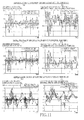
- Figs. 8 , 9 (a) , 10 and 11 (a), (c), (e) show the actual value Vs* and estimated value Vs' of the absorber expansion/contraction velocity.
- FIG. 8 shows the actual value Vs* and estimated value Vs' of the absorber expansion/contraction velocity when the performance of the electromagnetic suspension unit 4 is not changed.
- the estimated value Vs' and actual value Vs* are well coincident with each other.
- Figs. 9 (a) , 10 and 11 (a), (c), (e) show the actual value Vs* and estimated value Vs' of the absorber expansion/contraction velocity when the electromagnetic suspension unit 4 has a portion whose performance is changed.
- the actual value Vb* of an operation velocity (hereinafter referred to as electric actuator expansion/contraction velocity) of the electric actuator 16 is obtained.
- the electric actuator expansion/contraction velocity is a velocity Vb of change of a distance between the sprung portion 144 and intermediate mass 140.
- the actual value Vb* is obtained based on a detected value ⁇ * detected by the rotational angle sensor 162 and a lead L of the screw shaft 54.
- Vb * L ⁇ d ⁇ * / dt
- the estimated value Vb' is obtained by subtracting the estimated value (dx 3 /dt)' of the absolute velocity of the intermediate mass 140 from the estimated value (dx 2 /dt)' of the absolute velocity of the sprung portion 144.
- the estimated value (dx 2 /dt)' of the absolute velocity of the sprung portion 144 and the estimated value (dx 3 /dt)' of the absolute velocity of the intermediate mass 140 are obtained by the observer.
- Vb ⁇ dx 2 / dt ⁇ ⁇ - dx 3 / dt ⁇ ⁇
- a state in which friction acting (between the screw shaft 54 and the nut member 52) in the ball screw mechanism 77 is large, a state in which the screw shaft 54 cannot be moved due to bite of the screw shaft 54 and the nut member 52 into each other and a state in which the electric motor 50 is locked correspond to such a change of the performance of the electric actuator 16.
- the electric motor 50 is controlled in accordance with a predetermined rule, an amount of operation of the electric actuator 16 is increased to a certain degree.
- the friction in the motion converting mechanism 77 is small since the mechanism 77 includes the ball screw mechanism, so that, merely, the damping force is generated depending on the expansion/contraction velocity.
- Fig. 9 (b) shows the estimated value Vb' and actual value Vb* of the electric actuator expansion/contraction velocity when the friction between the screw shaft 54 and the nut member 52 is considerably large (when the motion converting mechanism 77 is close to its lock state).
- the actual value Vb* is made considerably small as compared to the estimated value Vb'.
- the lock-tendency-change threshold value SRth is set to a small value, namely, where the predetermined value ⁇ b is set to a large value, it can be detected that the friction is considerably made large due to bite of the screw shaft 54 and the nut member 52 into each other or that the electric motor 50 is locked, when the integral ⁇
- the lock-tendency-change threshold value SRth is set to a large value, namely, where the predetermined value ⁇ b is set to a small value, it can be detected that the resistance in the electric actuator 16 is made larger than a value in accordance with the estimation model 210, when the integral ⁇
- the predetermined value ⁇ b can be set in view of such circumstances. Further, the predetermined value ⁇ b can be set in a plurality of steps. It is noted that the lock-tendency-change threshold value SRth may be also set to a value obtained by multiplying the integral ⁇
- S21 is implemented to obtain the integral ⁇
- SAth expansion/contraction-resistance deficiency threshold value
- a state in which the damping force is deficient due to fluid leakage and oil deterioration a state in which the friction is made small due to deterioration of a sealing portion between the piston 80 and cylinder body 78 and a state in which spring force of the compression coil springs 84, 86 is deficient correspond to such a change of the performance of the hydraulic shock absorber 18.
- the damping force the "performance change toward reduction of the expansion/contraction resistance” may be referred also to as "performance change toward deficiency of the damping force”.
- Fig. 10 shows the actual value Vs* and estimated value Vs' of the absorber expansion/contraction velocity of the hydraulic shock absorber 18 in a state in which the expansion/contraction resistance in the shock absorber 18 is deficient.
- the actual value Vs* is larger than the estimated value Vs' as is clear from Fig. 10 .
- the actual value or the like of the absorber-expansion/contraction-related amount is made larger than the estimated value or the like of the absorber-expansion/contraction-related amount.
- the predetermined value ⁇ s is set to a small value whereby the expansion/contraction-resistance deficiency threshold value SAth is set to a small value, it can be detected that the expansion/contraction resistance force of the hydraulic shock absorber 18 is somewhat deficient, when the integral ⁇
- the predetermined value ⁇ s may be set to 0.
- the expansion/contraction-resistance deficiency threshold value SAth may be also set to a value obtained by multiplying the integral ⁇
- an actual value V H * of velocity of change of distance between the sprung and unsprung portions 144, 142 can be obtained as a differential of a detected value H* detected by the vehicle height sensor 154.
- V H * dH * / dt
- an estimated value V H ' of the velocity of the change of the distance between the sprung and unsprung portions 144, 142 can be obtained by subtracting an actual value (dx 1 / dt)* of an absolute velocity of the unsprung portion 142 from an estimated value (dx 2 / dt)' of an absolute velocity of sprung portion 144.
- the actual value (dx 1 / dt)* of the absolute velocity of the unsprung portion 142 can be obtained as an integral of a detected value that is detected by the unsprung-portion acceleration sensor 152.
- V H ⁇ ⁇ dx 2 / dt ⁇ ⁇ - dx 1 / dt *
- ⁇ V H ⁇ ⁇ V H * - V H ⁇ ⁇ ⁇ V H ⁇ Hth
- S24 is implemented when a negative judgment (NO) is obtained in S22. Therefore, S24 through S26 are implemented when the actual value or the like of the absorber-expansion/contraction-related amount is smaller than the estimated value or the like of the absorber-expansion/contraction-related amount.
- the actual value or the like of the absorber-expansion/contraction-related amount is made smaller than the estimated value or the like of the absorber-expansion/contraction-related amount when the performance of the electric actuator 16 is changed such that the actuator 16 becomes closer to the free state and when the performance of the shock absorber 18 is changed such that resistance in the absorber 18 is increased.
- the present electromagnetic suspension unit 4 is designed such that the expansion/contraction of the shock absorber 18 is smaller than the expansion/contraction of the electric actuator 16. Therefore, when the difference between the actual value or the like and the estimated value or the like of the sprung/unsprung-portions-distance-related amount is small, it can be considered that the performance change of the suspension unit 4 is caused by the shock absorber 18. When the difference is large, it can be considered that the performance change of the suspension unit 4 is caused by the electric actuator 16. Therefore, when the difference between the actual value or the like and the estimated value or the like of the sprung/unsprung-portions-distance-related amount is small, it is judged that the resistance in the shock absorber 18 is increased. When the difference is large, it is judged that the performance of the electric actuator 16 is changed such that the actuator 16 becomes closer to the free state.
- Fig. 11 (b) shows the estimated value V H' and actual value V H * of the velocity of the change of the distance between the sprung and unsprung portions 144, 142 when the hydraulic shock absorber 18 is locked, namely, when the actual value Vs* of the absorber expansion/contraction velocity becomes substantially zero (see Fig. 11 (a) ).
- the hydraulic shock absorber 18 is locked, for example, when valves provided in the piston 80 and base valve body 116 of a damping-force generating mechanism are stuck closed, when all communication passages of the damping-force generating mechanism are closed due to entrance of foreign matters into the passages or when the piston 80 cannot be moved by the foreign matters.
- Fig. 11 (b) shows the estimated value V H' and actual value V H * of the velocity of the change of the distance between the sprung and unsprung portions 144, 142 when the hydraulic shock absorber 18 is locked, namely, when the actual value Vs* of the absorber expansion/contraction velocity becomes substantially zero (see Fig. 11 (a) ).
- FIG. 11 (d) shows the estimated value V H ' and actual value V H * of the velocity of the change of the distance between the sprung and unsprung portions 144, 142 when the expansion/contraction resistance in the hydraulic shock absorber 18 is slightly larger than a value in accordance with the estimation model 210 (see Fig. 11 (c) ).
- the difference between the estimated value V H ' and actual value V H * is small as is clear from Figs. 11 (b), (d) .
- Fig. 11 (c) shows the estimated value V H ' and actual value V H * of the velocity of the change of the distance between the sprung and unsprung portions 144, 142 when the expansion/contraction resistance in the hydraulic shock absorber 18 is slightly larger than a value in accordance with the estimation model 210 (see Fig. 11 (c) ).
- the particular threshold value Hth is set to a value that enables distinction therebetween, and may be, for example, a value that is larger than the integral ⁇
- the performance change of the electric actuator 16 and the performance change of the shock absorber 18 are distinguished from each other. Further, since a portion of the electromagnetic suspension unit 4 suffering from the performance change is specified and then the specified portion is informed, there is an advantage that it is not necessary to replace an entirety of the electromagnetic suspension unit 4.
- the sprung-portion acceleration sensor 150, unsprung-portion acceleration sensor 152, vehicle height sensor 154 and rotational angle sensor 162 cooperate with portions of the suspension ECU 156 which are assigned to store and execute the performance inspection program represented by the flow chart of Fig. 6 , to constitute a performance-change detecting device.
- a portion of the performance-change detecting device which is provided by the vehicle height sensor 154, rotational angle sensor 162 and portions of the suspension ECU 156 assigned to store and implement S12, constitutes an actual absorber-expansion/contraction-related amount obtaining portion.
- a portion of the performance-change detecting device which is provided by the unsprung-portion acceleration sensor 152, ammeter 164 and portions of the suspension ECU 156 assigned to store and implement S13 and S14, constitutes an absorber-expansion/contraction-related amount estimating portion.
- a portion of the performance-change detecting device which is provided by portions of the suspension ECU 156 assigned to store and implement S15 through S18, S22 and S23, constitutes a comparison-based performance-change detecting portion.
- a portion of the comparison-based performance-change detecting portion which is provided by portions of the suspension ECU 156 assigned to store and implement S15 through S17, constitutes a performance-change-presence detecting portion.
- a portion of the comparison-based performance-change detecting portion which is provided by portions of the suspension ECU 156 assigned to store and implement S22 and S23, constitutes a expansion/contraction-resistance deficiency detecting portion.
- the actual absorber-expansion/contraction-related amount obtaining portion serves also as an actual expansion/contraction-related-amount calculating portion.
- the absorber-expansion/contraction- related amount estimating portion serves also as an observer-based expansion/contraction-related amount estimating portion.
- a portion of the performance-change detecting device which is provided by portions of the suspension ECU 156 assigned to store and implement S18 through S20 and S25 through S28, constitutes a performance-changed-portion specifying portion.
- a portion of the performance-changed-portion specifying portion which is provided by portions of the suspension ECU 156 assigned to store and implement S19 and S20, constitutes a lock-tendency-change detecting portion.
- a performance-changed-portion specifying routine represented by flow chart of Fig. 7 may be executed.
- the actual value Vs* of the expansion/contraction velocity of the shock absorber 18 upon application of vibration of a high frequency is obtained, and the integral ⁇
- a high frequency component may be extracted from the actual value Vs* that has been obtained in S12, so that the integral ⁇
- S41 through S43 may be implemented in a state in which vibration of a high frequency is being applied to the electromagnetic suspension unit 4 from an external device such as vibrating device. In this case, it is possible to cause the suspension unit 4 to be vibrated at a desired frequency.
- S41 through S43 may be implemented when the integral ⁇
- a predetermined value that is larger than 0.
- Vs* of the expansion/contraction velocity does not include a high frequency component. This arrangement is effective, in such a case, to prevent a positive judgment (YES) from being obtained in S42 and accordingly prevent judgment that the expansion/contraction resistance is large.
- the integrals of the absolute values of the actual and estimated values Vb* and Vb' of the electric actuator expansion/contraction velocity are obtained in S18 and the obtained integrals are compared to each other in S19.
- S18 may be implemented to obtain the integral ⁇
- S19 may be implemented to judge to whether or not the integral ⁇
- the lock-tendency-change threshold value Sbth used in S19 of the flow chart of Fig. 6 may be referred to as a relative lock-tendency-change threshold value
- the lock-tendency-change threshold value Sbtha of the present embodiment may be referred to as an absolute lock-tendency-change threshold value.
- the performance change of the electromagnetic suspension unit 4 may be detected by comparing an actual value and an estimated value of an intermediate-member-movement-related amount that is at least one of displacement and absolute velocity of the intermediate mass 140.
- estimated values x 3 ', (dx 3 / dt)' of the displacement x 3 and absolute velocity dx 3 / dt of the intermediate mass 140 are estimated in accordance with the estimation model 210, by the observer.
- an actual value Vm* ⁇ (dx3 / dt)* ⁇ of the absolute velocity of the intermediate mass 140 is calculated in accordance with the above expression (4).
- is compared to the intermediate-member-movement-based threshold value Smth, so that it is detected whether the performance change is present or absent.
- the unsprung-portion acceleration sensor 152 and ammeter 162 cooperate with portions of the suspension ECU 156, which are assigned to store and implement S13, to constitute an intermediate-member-movement-related-amount estimating portion.
- the unsprung-portion acceleration sensor 152 and ammeter 162 cooperate with portions of the suspension ECU 156, which are assigned to store and implement S14', to constitute an intermediate-member-movement-related-amount obtaining portion.
- the unsprung-portion acceleration sensor 152 and ammeter 162 cooperate with portions of the suspension ECU 156, which are assigned to store and implement S16', to constitute an intermediate-member-movement-based performance-change detecting portion.
- the actual value Vs* and estimated value Vs' of the absorber expansion/contraction velocity are compared to each other.
- an actual value Ls* and an estimated value Ls' of the expansion/contraction amount of the hydraulic shock absorber 18 or an actual value Ls* and an estimated value Ls' of a length (distance between the bottom surface of the transmitting member 82 and a contact position in which the absorber housing 30 and the mount portion 98) of the shock absorber 18 may be compared to each other.
- the comparison between the actual value V H * and estimated value V H ' of the velocity V H of the change of the distance between the sprung and unsprung portions 144, 142 may be replaced by comparison between the actual value H* and estimated value H' of the change of the distance between the sprung and unsprung portions 144, 142.
- the comparison between the actual value Vb* and estimated value Vb' of the electric actuator expansion/contraction velocity may be replaced by comparison between the actual value Lb* and estimated value Lb' of the expansion/contraction amount or length (distance between the bottom surface of the transmitting member 82 and the body-side portion 14 in the present embodiment).
- the judgment as to whether or not the performance is changed may be made when the same judgment result is obtained consecutively a plurality of times.
- the judgment may be made with provision of hysteresis. That is, even when the performance change is detected, it can be judged that it is not the performance change in case of satisfaction of another condition (which is close to a normal condition such as a lower threshold value) that is different from a performance-change judging condition. Owing to the provision of hysteresis, it is possible to avoid frequent change of the result in the judgment as to whether or not the performance is changed (namely, avoid hunting in the judgment result).
- Fig. 13 An example of such an arrangement is shown in Fig. 13 .
- Flow chart of Fig. 13 represents a part of the performance inspection program.
- S11 through S21 and S24 through S28 are implemented in the same manner as in the above-described embodiment.
- Fig. 13 In the present embodiment with the arrangement shown in Fig.
- the predetermined value ⁇ s is set to two values different from each other and the expansion/contraction-resistance deficiency threshold value SAth is set to two values different from each other in the judgment as to whether or not the integral ⁇
- First expansion/contraction-resistance deficiency threshold value SAth1 ⁇
- Second expansion/contraction-resistance deficiency threshold value SAth2 ⁇
- SAth1 ⁇
- the performance change is detected by comparing the actual value Vs* and estimated value Vs' of the absorber expansion/contraction velocity
- the performance change may be detected by comparing the actual values Vs* of the expansion/contraction velocities of the shock absorbers 18 that are provided for respective four wheels.
- An example of a performance inspection program used in such an arrangement is shown in Fig. 14 .
- the present performance inspection program is also executed during running of the vehicle.
- each of the hydraulic shock absorbers 18 is detected by comparing the actual values Vs* of the expansion/contraction velocities of the shock absorbers 18 provided for the front right, front left, rear right and rear left wheels.
- S52 is implemented to obtain the integrals ⁇
- S53 is implemented to obtain an average [ ⁇
- of the absolute values of the actual values Vsij* with respect to the electromagnetic suspension units 4ij provided for the assessed wheels are sequentially subjected to a judgment as to whether or not each of the integrals ⁇
- with respect to the assessed wheel is smaller than the average [ ⁇
- the no-performance-change judgment counter Nij When the integral ⁇
- the positive judgment (YES) cannot be obtained both in S54 and S57. Therefore, when the performance change of the hydraulic shock absorber18ij is detected, the negative judgment (NO) is obtained in S54 or S57, so that a value of the no-performance-change judgment counter Nij becomes 1.
- the value of the no-performance-change judgment counter Nij becomes 2.
- a cumulative rotational angle ⁇ ij* of each of the electric motors 50 (provided for the respective wheels) over a predetermined time period is detected.
- an average [ ⁇ ij*] of the cumulative rotational angles ⁇ ij* with respect to the front right, front left, rear right and rear left electromagnetic suspension units 4 is obtained.
- the cumulative rotational angles ⁇ ij* with respect to the assessed wheels are sequentially subjected to a judgment as to whether or not each of the cumulative rotational angle ⁇ ij* is larger than the average [ ⁇ ij*] by a predetermined value ⁇ 1 or more.
- each of the above-described predetermined values ⁇ V1, ⁇ V2, ⁇ 1, ⁇ 2 may be either a predetermined fixed value or a value dependent on a corresponding one of the averages [ ⁇
- a predetermined range of the absorber-expansion/contraction-related amount is determined depending on the average [ ⁇
- a predetermined range of number of rotation of the motor 50 is determined depending on the average [ ⁇ ij*] and predetermined values ⁇ 1, ⁇ 2.
- the vehicle height sensors 154 and rotational angle sensors 162 cooperate with portions of the suspension ECU 156 which are assigned to store and implement S51 through S59, to constitute a wheels-comparison-based performance-change detecting portion.
- a portion of the wheels-comparison-based performance-change detecting portion which is provided by the rotational angle sensors 162 and portions of the suspension ECU 156 assigned to store and implement S60 through S67, constitutes a wheels-comparison-based electric-actuator-performance-change detecting portion.
- a portion of the wheels-comparison-based electric-actuator-performance-change detecting portion which is provided by the rotational angle sensors 162 and portions of the suspension ECU 156 assigned to store and implement S60, constitutes an electric-operation-related-amount obtaining portion.
- estimation model 210 is used in the above-described embodiment, it is possible to use an estimation model 280 as shown in Fig. 15 .
- the estimation model 280 is different from the estimation model 210 in that the suspension spring 20 is not provided in the model 280.
- a performance inspection program represented by flow chart of Fig. 16 is executed.
- the present performance inspection program is substantially the same as the program executed in the above-described embodiment, but is different from the program executed in the above-described embodiment, with respect to implementations of S24 through S28.
- the suspension spring 20 Since the suspension spring 20 is not taken into consideration in the estimation model 280, it is preferable to detect the performance change, by comparing the estimated value Vs' and actual value Vs* of the absorber expansion/contraction velocity upon application of vibration of a low frequency, or by comparing low-frequency components of the estimated value Vs' and actual value Vs* of the absorber expansion/contraction velocity, rather than based on the velocity V H of the change of the distance between the sprung and unsprung portions 144, 142. In this sense, the actual value Vs* and estimated value Vs' of the absorber expansion/contraction velocity are subjected to low-pass filter processing in S81.
- the electromagnetic suspension unit 4 in which the shock absorber 18 and the electric actuator 16 are disposed in series to each other, between the sprung portion 144 and unsprung portion 142.
- the invention is equally applicable to an electromagnetic suspension unit in which an electric actuator and a shock absorber are disposed in parallel with each other.
- An example of this parallel arrangement is shown in Figs. 17 and 18 .
- a suspension spring 308, an electric actuator 310 and a hydraulic shock absorber 312 are disposed in parallel between the wheel-side portion12 and the body-side portion 14.
- the hydraulic shock absorber 312 includes a cylinder body 314 and a piston 316 that is slidably fitted in the cylinder body 314.
- the cylinder body 314 is connected to the wheel-side portion12.
- a piston rod 318 of the piston 316 is provided to extend through inside a screw shaft 320, and is connected to the body-side portion 14.
- the piston 316 has a communication passage through which upper and lower chambers are to be brought into communication with each other.
- a cross sectional area of the communication passage is adjustable by an electromagnetic valve 322.
- an outer sleeve 330 and an inner sleeve 332 are provided between the cylinder body 314 and the body-side portion 14.
- the inner sleeve 332 is fitted in the outer sleeve 330 such that these sleeves 330, 332 are slidable relative to each other.
- the outer sleeve 330 is attached to the cylinder body 314, and is unmovable relative to the cylinder body 314 in the vertical direction.
- the inner sleeve 332 is attached to the body-side portion 14, and is, in principle, unmovable relative to the body-side portion 14 in the vertical direction.
- the outer and inner sleeves 330, 332 are held in fitting engagement with each other by engagement of a pair of guide grooves and keys, and are vertically unmovable relative to each other and unrotatable relative to each other.
- the suspension spring 308 is disposed between the body-side portion 14 and the outer sleeve 330 (cylinder body 314).
- the electric actuator 310 includes an electric motor 340 and a force transmitting mechanism 342 which is provided to transmit a drive force of the electric motor 340 to the outer sleeve 330.
- the force transmitting mechanism 342 includes, in addition to the screw shaft 320 which is attached to an output shaft of the electric motor 340 and which is unrotatable relative to the output shaft of the motor 340, a nut member 344 which is held in thread engagement with the screw shaft 320, and an elongated member 346 which is fixed to the nut member 344 and the outer sleeve 330.
- an actual value of the distance between the wheel-side portion 12 and body-side portion 14 is detected by the vehicle height sensor 154.
- the distance between the sprung and unsprung portions 144, 142 corresponds to an expansion/contraction amount of the shock absorber 312.
- an estimated value of the distance between the sprung and unsprung portions 144, 142 is obtained in accordance with an estimation model 360 of Fig. 18 .
- the lower arm 12, cylinder body 314 and outer sleeve 330 cooperate with one another to constitute an unsprung portion 362, while the inner sleeve 332, body-side portion 14, piston 316 and piston rod 318 cooperate with one another to constitute a sprung portion 364.
- a spring coefficient of the suspension sprung 308 is represented by "Ks”.
- a damping coefficient of the shock absorber 312 is represented by "Cs" (variable).
- a displacement and an absolute velocity of the sprung portion 364 are estimated based on a displacement and an absolute velocity of the unsprung portion 362 and an output Fm of the electric motor 340, whereby estimated values of the expansion/contraction amount and velocity of the shock absorber 312 can be obtained.
- the electromagnetic suspension unit may have a construction that is not particularly limited.
- the present invention is applicable to any one of electromagnetic suspension units having various kinds of constructions, thereby making it possible to detect change of the performance of any one of the various suspension units.
- the performance change is detected while the electric motor 50, 340 is being controlled. However, it is possible to detect the performance change even while the motor 50, 340 is not being controlled. In this case, the damping force is generated by the electric motor 50, 340, so that the damping force generated by the motor 50, 340 can be obtained as an estimated value of the motor output Fm. Further, in the above-described embodiments, the performance change is detected during running of the vehicle. However, this arrangement is not essential. That is, even during stopping of the vehicle, the performance change can be detected by vibrating the vehicle.
- the vehicle is vibrated by forcedly activating the electric actuator with supply of an electric current to the electric motor for a predetermined time period, and then the supply of the electric current to the motor is stopped.
- the performance change can be detected based on state of the expansion/contraction of the shock absorber after the supply of the electric current has been stopped.
Landscapes
- Engineering & Computer Science (AREA)
- Mechanical Engineering (AREA)
- Vehicle Body Suspensions (AREA)
- Vibration Prevention Devices (AREA)
Applications Claiming Priority (1)
| Application Number | Priority Date | Filing Date | Title |
|---|---|---|---|
| PCT/JP2008/071804 WO2010064291A1 (fr) | 2008-12-01 | 2008-12-01 | Système de suspension électromagnétique |
Publications (3)
| Publication Number | Publication Date |
|---|---|
| EP2364866A1 true EP2364866A1 (fr) | 2011-09-14 |
| EP2364866A4 EP2364866A4 (fr) | 2012-10-17 |
| EP2364866B1 EP2364866B1 (fr) | 2013-08-28 |
Family
ID=42232956
Family Applications (1)
| Application Number | Title | Priority Date | Filing Date |
|---|---|---|---|
| EP08876946.8A Not-in-force EP2364866B1 (fr) | 2008-12-01 | 2008-12-01 | Système de suspension électromagnétique |
Country Status (5)
| Country | Link |
|---|---|
| US (1) | US8793052B2 (fr) |
| EP (1) | EP2364866B1 (fr) |
| JP (1) | JP5115624B2 (fr) |
| CN (1) | CN101821119B (fr) |
| WO (1) | WO2010064291A1 (fr) |
Cited By (2)
| Publication number | Priority date | Publication date | Assignee | Title |
|---|---|---|---|---|
| WO2013117816A1 (fr) * | 2012-02-07 | 2013-08-15 | Wärtsilä Finland Oy | Détection d'un dysfonctionnement d'un élément amortisseur |
| FR2991238A1 (fr) * | 2012-05-29 | 2013-12-06 | Alexandre Forestier | Systeme de generation d'energie electrique pour vehicule automobile |
Families Citing this family (24)
| Publication number | Priority date | Publication date | Assignee | Title |
|---|---|---|---|---|
| US8465025B2 (en) | 2010-08-31 | 2013-06-18 | Oshkosh Corporation | Gas spring assembly for a vehicle suspension |
| US8262100B2 (en) * | 2010-09-28 | 2012-09-11 | Georges Thomas | Vehicle height adjustment suspension device |
| DE102010042673A1 (de) * | 2010-10-20 | 2012-04-26 | Deere & Company | Stabilisierungsvorrichtung für ein Kraftfahrzeug |
| DE112013003296T5 (de) * | 2012-06-29 | 2015-03-26 | Hitachi Automotive Systems, Ltd. | Krafterzeugungsmechanismus |
| US10564071B2 (en) | 2014-05-28 | 2020-02-18 | Showa Corporation | Method and system for inspecting damping force variable mechanism, and method for inspecting pressure damping device |
| FR3032686B1 (fr) * | 2015-02-18 | 2017-03-10 | Messier Bugatti Dowty | Atterrisseur d'aeronef comprenant une tige lineaire telescopique |
| KR20170112040A (ko) | 2016-03-30 | 2017-10-12 | 현대자동차주식회사 | 전자제어현가장치의 전자제어유닛 장착 판별장치 및 그 방법 |
| US11358431B2 (en) * | 2017-05-08 | 2022-06-14 | Apple Inc. | Active suspension system |
| JP6480983B2 (ja) * | 2017-06-16 | 2019-03-13 | 本田技研工業株式会社 | 電磁サスペンション装置 |
| US10899340B1 (en) | 2017-06-21 | 2021-01-26 | Apple Inc. | Vehicle with automated subsystems |
| JP6989445B2 (ja) * | 2018-06-01 | 2022-01-05 | 本田技研工業株式会社 | 電磁サスペンション装置 |
| IL260472B (en) | 2018-07-08 | 2020-03-31 | Israel Aerospace Ind Ltd | Load limiter with energy absorting element |
| CN109080399B (zh) * | 2018-07-30 | 2021-10-12 | 江苏大学 | 一种可实现自供能的混合电磁悬架及其控制方法 |
| US11634167B1 (en) | 2018-09-14 | 2023-04-25 | Apple Inc. | Transmitting axial and rotational movement to a hub |
| CN111137090B (zh) * | 2018-11-05 | 2021-09-07 | 宝沃汽车(中国)有限公司 | 主动悬架系统以及车辆 |
| US11511587B2 (en) * | 2018-12-27 | 2022-11-29 | Continental Automotive Systems, Inc. | Integrated crosslink valve |
| US11084349B2 (en) * | 2019-01-31 | 2021-08-10 | Tenneco Automotive Operating Company Inc. | Leaf spring and actuator control systems and methods |
| JP6923591B2 (ja) * | 2019-04-12 | 2021-08-18 | 本田技研工業株式会社 | 電動サスペンション装置 |
| JP6840184B2 (ja) * | 2019-04-12 | 2021-03-10 | 本田技研工業株式会社 | 電動サスペンション装置 |
| JP7367652B2 (ja) * | 2020-10-07 | 2023-10-24 | トヨタ自動車株式会社 | 車両用プレビュー制振制御装置及び方法 |
| CN112549892B (zh) * | 2020-12-04 | 2022-02-15 | 江苏大学 | 附加刚度阻尼可调的二级减振液电式主动悬架及工作方法 |
| CN113983981A (zh) * | 2021-10-22 | 2022-01-28 | 重庆长安汽车股份有限公司 | 阻尼连续可调减振器的簧上和簧下位移的获取方法 |
| CN117465180B (zh) * | 2023-10-31 | 2024-05-17 | 西南交通大学 | 面向驾乘体验提升的可调负刚度空簧总成及系统控制方法 |
| CN117719554B (zh) * | 2024-02-18 | 2024-04-26 | 成都磁速科技有限公司 | 高温超导磁悬浮轨道巡检预警系统 |
Citations (2)
| Publication number | Priority date | Publication date | Assignee | Title |
|---|---|---|---|---|
| EP0436870A2 (fr) * | 1990-01-08 | 1991-07-17 | General Electric Company | Système dynamique de suspension de véhicules avec moteur commuté électroniquement |
| JP2005162021A (ja) * | 2003-12-03 | 2005-06-23 | Toyota Motor Corp | 車両安定化制御装置 |
Family Cites Families (14)
| Publication number | Priority date | Publication date | Assignee | Title |
|---|---|---|---|---|
| JPS6079030A (ja) | 1983-10-04 | 1985-05-04 | Sumitomo Chem Co Ltd | 硬化促進効果を有するエポキシ樹脂組成物 |
| JPS6079030U (ja) * | 1983-11-05 | 1985-06-01 | 日産自動車株式会社 | シヨツクアブソ−バの異常検出装置 |
| JPH07444B2 (ja) * | 1985-08-16 | 1995-01-11 | マツダ株式会社 | 車高調整装置 |
| JP2834194B2 (ja) | 1989-07-14 | 1998-12-09 | 株式会社日立製作所 | ハードウエアモニタ |
| JP3046040B2 (ja) | 1990-06-30 | 2000-05-29 | マツダ株式会社 | 車両のサスペンション装置 |
| US5681579A (en) | 1993-03-22 | 1997-10-28 | E.R. Squibb & Sons, Inc. | Polymeric support wound dressing |
| JPH06344745A (ja) * | 1993-06-14 | 1994-12-20 | Aisin Seiki Co Ltd | サスペンション制御系の脱調検出装置 |
| JP3629137B2 (ja) | 1997-03-03 | 2005-03-16 | トヨタ自動車株式会社 | 車両用サスペンション装置のための電気制御装置 |
| JP2005035486A (ja) | 2003-07-18 | 2005-02-10 | Toyota Motor Corp | 車両懸架装置 |
| JP4275551B2 (ja) | 2004-03-11 | 2009-06-10 | カヤバ工業株式会社 | アクティブサスペンションの自己診断装置 |
| JP4464798B2 (ja) | 2004-11-24 | 2010-05-19 | トヨタ自動車株式会社 | 車両用サスペンション装置 |
| JP4500661B2 (ja) | 2004-12-13 | 2010-07-14 | カヤバ工業株式会社 | 異常検出装置 |
| JP2008296802A (ja) | 2007-06-01 | 2008-12-11 | Toyota Motor Corp | 車両用サスペンションシステム |
| JP2009023624A (ja) | 2007-07-24 | 2009-02-05 | Toyota Motor Corp | 車両用サスペンションシステム |
-
2008
- 2008-12-01 CN CN2008801085300A patent/CN101821119B/zh not_active Expired - Fee Related
- 2008-12-01 JP JP2010509614A patent/JP5115624B2/ja not_active Expired - Fee Related
- 2008-12-01 EP EP08876946.8A patent/EP2364866B1/fr not_active Not-in-force
- 2008-12-01 US US12/678,945 patent/US8793052B2/en active Active
- 2008-12-01 WO PCT/JP2008/071804 patent/WO2010064291A1/fr active Application Filing
Patent Citations (2)
| Publication number | Priority date | Publication date | Assignee | Title |
|---|---|---|---|---|
| EP0436870A2 (fr) * | 1990-01-08 | 1991-07-17 | General Electric Company | Système dynamique de suspension de véhicules avec moteur commuté électroniquement |
| JP2005162021A (ja) * | 2003-12-03 | 2005-06-23 | Toyota Motor Corp | 車両安定化制御装置 |
Non-Patent Citations (1)
| Title |
|---|
| See also references of WO2010064291A1 * |
Cited By (3)
| Publication number | Priority date | Publication date | Assignee | Title |
|---|---|---|---|---|
| WO2013117816A1 (fr) * | 2012-02-07 | 2013-08-15 | Wärtsilä Finland Oy | Détection d'un dysfonctionnement d'un élément amortisseur |
| FR2991238A1 (fr) * | 2012-05-29 | 2013-12-06 | Alexandre Forestier | Systeme de generation d'energie electrique pour vehicule automobile |
| FR2991237A1 (fr) * | 2012-05-29 | 2013-12-06 | Alexandre Forestier | Systeme de generation d'energie electrique pour vehicule automobile |
Also Published As
| Publication number | Publication date |
|---|---|
| US8793052B2 (en) | 2014-07-29 |
| EP2364866B1 (fr) | 2013-08-28 |
| JPWO2010064291A1 (ja) | 2012-04-26 |
| CN101821119A (zh) | 2010-09-01 |
| JP5115624B2 (ja) | 2013-01-09 |
| WO2010064291A1 (fr) | 2010-06-10 |
| US20110218707A1 (en) | 2011-09-08 |
| EP2364866A4 (fr) | 2012-10-17 |
| CN101821119B (zh) | 2012-03-14 |
Similar Documents
| Publication | Publication Date | Title |
|---|---|---|
| EP2364866B1 (fr) | Système de suspension électromagnétique | |
| RU2448000C2 (ru) | Система подвески для транспортного средства, содержащая электромагнитный привод | |
| EP2244894B1 (fr) | Système de suspension pour véhicule | |
| EP2285605B1 (fr) | Système de suspension pour véhicule | |
| KR101563448B1 (ko) | 차량 | |
| USRE34628E (en) | Automotive suspension system with variable damping characteristics | |
| EP0279507A2 (fr) | Système de contrôle pour dispositif de suspension de véhicule automobile | |
| EP2062756A1 (fr) | Systeme de suspension pour vehicule | |
| JP3059527U (ja) | 能動懸架装置 | |
| US20150061244A1 (en) | Method for tuning the suspension of a motor vehicle, and suspension strut | |
| EP0650859B1 (fr) | Commande d'amortissement avec estimation de la température de l'huile de l'amortisseur | |
| JP2009023624A (ja) | 車両用サスペンションシステム | |
| Mo et al. | A semiactive vibration absorber (SAVA) for automotive suspensions | |
| Galanti | Modelling, simulation and control for a skyhook suspension | |
| JP2013112313A (ja) | 減衰力調整式シリンダ装置 | |
| JP4664759B2 (ja) | ストロークセンサの異常判定装置 | |
| Mishra et al. | Design and Analysis of Suspension Test Rig | |
| KR102430488B1 (ko) | 차량용 능동형 현가장치 | |
| Walelign | Performance analysis of the electromagnetic suspension system under dynamic conditions for passenger car application | |
| JP2008230285A (ja) | 減衰力可変ダンパの制御装置 | |
| Mo et al. | A bistate control of a semiactive automotive suspension | |
| Delvecchio et al. | Semi‐Active Suspension Control in Two‐Wheeled Vehicles: a Case Study | |
| JP2009067201A (ja) | 車両用サスペンションシステム |
Legal Events
| Date | Code | Title | Description |
|---|---|---|---|
| PUAI | Public reference made under article 153(3) epc to a published international application that has entered the european phase |
Free format text: ORIGINAL CODE: 0009012 |
|
| 17P | Request for examination filed |
Effective date: 20100319 |
|
| AK | Designated contracting states |
Kind code of ref document: A1 Designated state(s): AT BE BG CH CY CZ DE DK EE ES FI FR GB GR HR HU IE IS IT LI LT LU LV MC MT NL NO PL PT RO SE SI SK TR |
|
| DAX | Request for extension of the european patent (deleted) | ||
| A4 | Supplementary search report drawn up and despatched |
Effective date: 20120917 |
|
| RIC1 | Information provided on ipc code assigned before grant |
Ipc: B60G 17/06 20060101ALI20120911BHEP Ipc: B60G 13/08 20060101ALI20120911BHEP Ipc: B60G 17/0185 20060101AFI20120911BHEP Ipc: B60G 17/015 20060101ALI20120911BHEP |
|
| RAP1 | Party data changed (applicant data changed or rights of an application transferred) |
Owner name: TOYOTA JIDOSHA KABUSHIKI KAISHA |
|
| GRAP | Despatch of communication of intention to grant a patent |
Free format text: ORIGINAL CODE: EPIDOSNIGR1 |
|
| GRAS | Grant fee paid |
Free format text: ORIGINAL CODE: EPIDOSNIGR3 |
|
| GRAA | (expected) grant |
Free format text: ORIGINAL CODE: 0009210 |
|
| RIN1 | Information on inventor provided before grant (corrected) |
Inventor name: INOUE, HIROFUMI Inventor name: HORIE, MASANORI |
|
| AK | Designated contracting states |
Kind code of ref document: B1 Designated state(s): AT BE BG CH CY CZ DE DK EE ES FI FR GB GR HR HU IE IS IT LI LT LU LV MC MT NL NO PL PT RO SE SI SK TR |
|
| REG | Reference to a national code |
Ref country code: GB Ref legal event code: FG4D |
|
| REG | Reference to a national code |
Ref country code: CH Ref legal event code: EP |
|
| REG | Reference to a national code |
Ref country code: AT Ref legal event code: REF Ref document number: 629113 Country of ref document: AT Kind code of ref document: T Effective date: 20130915 |
|
| REG | Reference to a national code |
Ref country code: IE Ref legal event code: FG4D |
|
| REG | Reference to a national code |
Ref country code: DE Ref legal event code: R096 Ref document number: 602008027221 Country of ref document: DE Effective date: 20131024 |
|
| REG | Reference to a national code |
Ref country code: AT Ref legal event code: MK05 Ref document number: 629113 Country of ref document: AT Kind code of ref document: T Effective date: 20130828 |
|
| REG | Reference to a national code |
Ref country code: LT Ref legal event code: MG4D |
|
| REG | Reference to a national code |
Ref country code: NL Ref legal event code: VDEP Effective date: 20130828 |
|
| PG25 | Lapsed in a contracting state [announced via postgrant information from national office to epo] |
Ref country code: PT Free format text: LAPSE BECAUSE OF FAILURE TO SUBMIT A TRANSLATION OF THE DESCRIPTION OR TO PAY THE FEE WITHIN THE PRESCRIBED TIME-LIMIT Effective date: 20131230 Ref country code: AT Free format text: LAPSE BECAUSE OF FAILURE TO SUBMIT A TRANSLATION OF THE DESCRIPTION OR TO PAY THE FEE WITHIN THE PRESCRIBED TIME-LIMIT Effective date: 20130828 Ref country code: NO Free format text: LAPSE BECAUSE OF FAILURE TO SUBMIT A TRANSLATION OF THE DESCRIPTION OR TO PAY THE FEE WITHIN THE PRESCRIBED TIME-LIMIT Effective date: 20131128 Ref country code: LT Free format text: LAPSE BECAUSE OF FAILURE TO SUBMIT A TRANSLATION OF THE DESCRIPTION OR TO PAY THE FEE WITHIN THE PRESCRIBED TIME-LIMIT Effective date: 20130828 Ref country code: SE Free format text: LAPSE BECAUSE OF FAILURE TO SUBMIT A TRANSLATION OF THE DESCRIPTION OR TO PAY THE FEE WITHIN THE PRESCRIBED TIME-LIMIT Effective date: 20130828 Ref country code: CY Free format text: LAPSE BECAUSE OF FAILURE TO SUBMIT A TRANSLATION OF THE DESCRIPTION OR TO PAY THE FEE WITHIN THE PRESCRIBED TIME-LIMIT Effective date: 20130619 Ref country code: HR Free format text: LAPSE BECAUSE OF FAILURE TO SUBMIT A TRANSLATION OF THE DESCRIPTION OR TO PAY THE FEE WITHIN THE PRESCRIBED TIME-LIMIT Effective date: 20130828 Ref country code: IS Free format text: LAPSE BECAUSE OF FAILURE TO SUBMIT A TRANSLATION OF THE DESCRIPTION OR TO PAY THE FEE WITHIN THE PRESCRIBED TIME-LIMIT Effective date: 20131228 |
|
| REG | Reference to a national code |
Ref country code: NL Ref legal event code: VDEP Effective date: 20130828 |
|
| PG25 | Lapsed in a contracting state [announced via postgrant information from national office to epo] |
Ref country code: PL Free format text: LAPSE BECAUSE OF FAILURE TO SUBMIT A TRANSLATION OF THE DESCRIPTION OR TO PAY THE FEE WITHIN THE PRESCRIBED TIME-LIMIT Effective date: 20130828 Ref country code: LV Free format text: LAPSE BECAUSE OF FAILURE TO SUBMIT A TRANSLATION OF THE DESCRIPTION OR TO PAY THE FEE WITHIN THE PRESCRIBED TIME-LIMIT Effective date: 20130828 Ref country code: BE Free format text: LAPSE BECAUSE OF FAILURE TO SUBMIT A TRANSLATION OF THE DESCRIPTION OR TO PAY THE FEE WITHIN THE PRESCRIBED TIME-LIMIT Effective date: 20130828 Ref country code: GR Free format text: LAPSE BECAUSE OF FAILURE TO SUBMIT A TRANSLATION OF THE DESCRIPTION OR TO PAY THE FEE WITHIN THE PRESCRIBED TIME-LIMIT Effective date: 20131129 Ref country code: FI Free format text: LAPSE BECAUSE OF FAILURE TO SUBMIT A TRANSLATION OF THE DESCRIPTION OR TO PAY THE FEE WITHIN THE PRESCRIBED TIME-LIMIT Effective date: 20130828 Ref country code: SI Free format text: LAPSE BECAUSE OF FAILURE TO SUBMIT A TRANSLATION OF THE DESCRIPTION OR TO PAY THE FEE WITHIN THE PRESCRIBED TIME-LIMIT Effective date: 20130828 |
|
| REG | Reference to a national code |
Ref country code: GB Ref legal event code: 746 Effective date: 20140304 |
|
| PG25 | Lapsed in a contracting state [announced via postgrant information from national office to epo] |
Ref country code: CY Free format text: LAPSE BECAUSE OF FAILURE TO SUBMIT A TRANSLATION OF THE DESCRIPTION OR TO PAY THE FEE WITHIN THE PRESCRIBED TIME-LIMIT Effective date: 20130828 |
|
| REG | Reference to a national code |
Ref country code: DE Ref legal event code: R084 Ref document number: 602008027221 Country of ref document: DE Effective date: 20140304 |
|
| PG25 | Lapsed in a contracting state [announced via postgrant information from national office to epo] |
Ref country code: DK Free format text: LAPSE BECAUSE OF FAILURE TO SUBMIT A TRANSLATION OF THE DESCRIPTION OR TO PAY THE FEE WITHIN THE PRESCRIBED TIME-LIMIT Effective date: 20130828 Ref country code: CZ Free format text: LAPSE BECAUSE OF FAILURE TO SUBMIT A TRANSLATION OF THE DESCRIPTION OR TO PAY THE FEE WITHIN THE PRESCRIBED TIME-LIMIT Effective date: 20130828 Ref country code: EE Free format text: LAPSE BECAUSE OF FAILURE TO SUBMIT A TRANSLATION OF THE DESCRIPTION OR TO PAY THE FEE WITHIN THE PRESCRIBED TIME-LIMIT Effective date: 20130828 Ref country code: NL Free format text: LAPSE BECAUSE OF FAILURE TO SUBMIT A TRANSLATION OF THE DESCRIPTION OR TO PAY THE FEE WITHIN THE PRESCRIBED TIME-LIMIT Effective date: 20130828 Ref country code: RO Free format text: LAPSE BECAUSE OF FAILURE TO SUBMIT A TRANSLATION OF THE DESCRIPTION OR TO PAY THE FEE WITHIN THE PRESCRIBED TIME-LIMIT Effective date: 20130828 Ref country code: SK Free format text: LAPSE BECAUSE OF FAILURE TO SUBMIT A TRANSLATION OF THE DESCRIPTION OR TO PAY THE FEE WITHIN THE PRESCRIBED TIME-LIMIT Effective date: 20130828 |
|
| PG25 | Lapsed in a contracting state [announced via postgrant information from national office to epo] |
Ref country code: IT Free format text: LAPSE BECAUSE OF FAILURE TO SUBMIT A TRANSLATION OF THE DESCRIPTION OR TO PAY THE FEE WITHIN THE PRESCRIBED TIME-LIMIT Effective date: 20130828 Ref country code: ES Free format text: LAPSE BECAUSE OF FAILURE TO SUBMIT A TRANSLATION OF THE DESCRIPTION OR TO PAY THE FEE WITHIN THE PRESCRIBED TIME-LIMIT Effective date: 20130828 |
|
| REG | Reference to a national code |
Ref country code: DE Ref legal event code: R097 Ref document number: 602008027221 Country of ref document: DE |
|
| PLBE | No opposition filed within time limit |
Free format text: ORIGINAL CODE: 0009261 |
|
| STAA | Information on the status of an ep patent application or granted ep patent |
Free format text: STATUS: NO OPPOSITION FILED WITHIN TIME LIMIT |
|
| REG | Reference to a national code |
Ref country code: CH Ref legal event code: PL |
|
| 26N | No opposition filed |
Effective date: 20140530 |
|
| PG25 | Lapsed in a contracting state [announced via postgrant information from national office to epo] |
Ref country code: LU Free format text: LAPSE BECAUSE OF FAILURE TO SUBMIT A TRANSLATION OF THE DESCRIPTION OR TO PAY THE FEE WITHIN THE PRESCRIBED TIME-LIMIT Effective date: 20131201 |
|
| REG | Reference to a national code |
Ref country code: DE Ref legal event code: R097 Ref document number: 602008027221 Country of ref document: DE Effective date: 20140530 |
|
| REG | Reference to a national code |
Ref country code: IE Ref legal event code: MM4A |
|
| PG25 | Lapsed in a contracting state [announced via postgrant information from national office to epo] |
Ref country code: CH Free format text: LAPSE BECAUSE OF NON-PAYMENT OF DUE FEES Effective date: 20131231 Ref country code: IE Free format text: LAPSE BECAUSE OF NON-PAYMENT OF DUE FEES Effective date: 20131201 Ref country code: LI Free format text: LAPSE BECAUSE OF NON-PAYMENT OF DUE FEES Effective date: 20131231 |
|
| PG25 | Lapsed in a contracting state [announced via postgrant information from national office to epo] |
Ref country code: MC Free format text: LAPSE BECAUSE OF FAILURE TO SUBMIT A TRANSLATION OF THE DESCRIPTION OR TO PAY THE FEE WITHIN THE PRESCRIBED TIME-LIMIT Effective date: 20130828 |
|
| PG25 | Lapsed in a contracting state [announced via postgrant information from national office to epo] |
Ref country code: TR Free format text: LAPSE BECAUSE OF FAILURE TO SUBMIT A TRANSLATION OF THE DESCRIPTION OR TO PAY THE FEE WITHIN THE PRESCRIBED TIME-LIMIT Effective date: 20130828 |
|
| PG25 | Lapsed in a contracting state [announced via postgrant information from national office to epo] |
Ref country code: BG Free format text: LAPSE BECAUSE OF FAILURE TO SUBMIT A TRANSLATION OF THE DESCRIPTION OR TO PAY THE FEE WITHIN THE PRESCRIBED TIME-LIMIT Effective date: 20130828 Ref country code: HU Free format text: LAPSE BECAUSE OF FAILURE TO SUBMIT A TRANSLATION OF THE DESCRIPTION OR TO PAY THE FEE WITHIN THE PRESCRIBED TIME-LIMIT; INVALID AB INITIO Effective date: 20081201 |
|
| PG25 | Lapsed in a contracting state [announced via postgrant information from national office to epo] |
Ref country code: MT Free format text: LAPSE BECAUSE OF FAILURE TO SUBMIT A TRANSLATION OF THE DESCRIPTION OR TO PAY THE FEE WITHIN THE PRESCRIBED TIME-LIMIT Effective date: 20130828 |
|
| REG | Reference to a national code |
Ref country code: FR Ref legal event code: PLFP Year of fee payment: 8 |
|
| REG | Reference to a national code |
Ref country code: FR Ref legal event code: PLFP Year of fee payment: 9 |
|
| REG | Reference to a national code |
Ref country code: FR Ref legal event code: PLFP Year of fee payment: 10 |
|
| PGFP | Annual fee paid to national office [announced via postgrant information from national office to epo] |
Ref country code: DE Payment date: 20211102 Year of fee payment: 14 Ref country code: FR Payment date: 20211109 Year of fee payment: 14 Ref country code: GB Payment date: 20211028 Year of fee payment: 14 |
|
| REG | Reference to a national code |
Ref country code: DE Ref legal event code: R119 Ref document number: 602008027221 Country of ref document: DE |
|
| GBPC | Gb: european patent ceased through non-payment of renewal fee |
Effective date: 20221201 |
|
| PG25 | Lapsed in a contracting state [announced via postgrant information from national office to epo] |
Ref country code: GB Free format text: LAPSE BECAUSE OF NON-PAYMENT OF DUE FEES Effective date: 20221201 Ref country code: DE Free format text: LAPSE BECAUSE OF NON-PAYMENT OF DUE FEES Effective date: 20230701 |
|
| PG25 | Lapsed in a contracting state [announced via postgrant information from national office to epo] |
Ref country code: FR Free format text: LAPSE BECAUSE OF NON-PAYMENT OF DUE FEES Effective date: 20221231 |