EP2362470A1 - Pile à combustible - Google Patents
Pile à combustible Download PDFInfo
- Publication number
- EP2362470A1 EP2362470A1 EP09830137A EP09830137A EP2362470A1 EP 2362470 A1 EP2362470 A1 EP 2362470A1 EP 09830137 A EP09830137 A EP 09830137A EP 09830137 A EP09830137 A EP 09830137A EP 2362470 A1 EP2362470 A1 EP 2362470A1
- Authority
- EP
- European Patent Office
- Prior art keywords
- gas flow
- flow channels
- fuel
- fuel cell
- separator
- Prior art date
- Legal status (The legal status is an assumption and is not a legal conclusion. Google has not performed a legal analysis and makes no representation as to the accuracy of the status listed.)
- Granted
Links
- 239000000446 fuel Substances 0.000 title claims abstract description 191
- 239000007789 gas Substances 0.000 claims abstract description 381
- 230000001590 oxidative effect Effects 0.000 claims abstract description 175
- 239000002737 fuel gas Substances 0.000 claims abstract description 108
- 239000012528 membrane Substances 0.000 claims abstract description 47
- 239000003054 catalyst Substances 0.000 claims abstract description 44
- 239000005518 polymer electrolyte Substances 0.000 claims abstract description 27
- 239000003792 electrolyte Substances 0.000 claims abstract description 20
- 230000005611 electricity Effects 0.000 claims description 14
- 229910052751 metal Inorganic materials 0.000 claims description 10
- 239000002184 metal Substances 0.000 claims description 10
- XLYOFNOQVPJJNP-UHFFFAOYSA-N water Substances O XLYOFNOQVPJJNP-UHFFFAOYSA-N 0.000 description 60
- 238000009792 diffusion process Methods 0.000 description 22
- 238000006243 chemical reaction Methods 0.000 description 15
- 230000032258 transport Effects 0.000 description 13
- OKTJSMMVPCPJKN-UHFFFAOYSA-N Carbon Chemical compound [C] OKTJSMMVPCPJKN-UHFFFAOYSA-N 0.000 description 11
- 229910052799 carbon Inorganic materials 0.000 description 10
- 238000009826 distribution Methods 0.000 description 9
- 239000001257 hydrogen Substances 0.000 description 9
- 229910052739 hydrogen Inorganic materials 0.000 description 9
- QVGXLLKOCUKJST-UHFFFAOYSA-N atomic oxygen Chemical compound [O] QVGXLLKOCUKJST-UHFFFAOYSA-N 0.000 description 8
- 239000001301 oxygen Substances 0.000 description 8
- 229910052760 oxygen Inorganic materials 0.000 description 8
- BASFCYQUMIYNBI-UHFFFAOYSA-N platinum Chemical compound [Pt] BASFCYQUMIYNBI-UHFFFAOYSA-N 0.000 description 8
- UFHFLCQGNIYNRP-UHFFFAOYSA-N Hydrogen Chemical compound [H][H] UFHFLCQGNIYNRP-UHFFFAOYSA-N 0.000 description 6
- 230000007423 decrease Effects 0.000 description 6
- 239000000463 material Substances 0.000 description 6
- 238000004088 simulation Methods 0.000 description 6
- 238000011144 upstream manufacturing Methods 0.000 description 6
- 239000002826 coolant Substances 0.000 description 5
- 230000003247 decreasing effect Effects 0.000 description 4
- 229910052697 platinum Inorganic materials 0.000 description 4
- 239000012495 reaction gas Substances 0.000 description 4
- WYTGDNHDOZPMIW-RCBQFDQVSA-N alstonine Natural products C1=CC2=C3C=CC=CC3=NC2=C2N1C[C@H]1[C@H](C)OC=C(C(=O)OC)[C@H]1C2 WYTGDNHDOZPMIW-RCBQFDQVSA-N 0.000 description 3
- 238000001816 cooling Methods 0.000 description 3
- 238000005516 engineering process Methods 0.000 description 3
- 150000002431 hydrogen Chemical class 0.000 description 3
- 239000003014 ion exchange membrane Substances 0.000 description 3
- 238000004519 manufacturing process Methods 0.000 description 3
- 230000007246 mechanism Effects 0.000 description 3
- 229920000642 polymer Polymers 0.000 description 3
- 229920001343 polytetrafluoroethylene Polymers 0.000 description 3
- 239000004810 polytetrafluoroethylene Substances 0.000 description 3
- 238000006479 redox reaction Methods 0.000 description 3
- 229920005989 resin Polymers 0.000 description 3
- 239000011347 resin Substances 0.000 description 3
- 239000004215 Carbon black (E152) Substances 0.000 description 2
- 229910000531 Co alloy Inorganic materials 0.000 description 2
- 229910000929 Ru alloy Inorganic materials 0.000 description 2
- CLBRCZAHAHECKY-UHFFFAOYSA-N [Co].[Pt] Chemical compound [Co].[Pt] CLBRCZAHAHECKY-UHFFFAOYSA-N 0.000 description 2
- 238000009833 condensation Methods 0.000 description 2
- 230000005494 condensation Effects 0.000 description 2
- 238000006073 displacement reaction Methods 0.000 description 2
- 239000010419 fine particle Substances 0.000 description 2
- 229920002313 fluoropolymer Polymers 0.000 description 2
- 239000004811 fluoropolymer Substances 0.000 description 2
- 229930195733 hydrocarbon Natural products 0.000 description 2
- 150000002430 hydrocarbons Chemical class 0.000 description 2
- 230000037427 ion transport Effects 0.000 description 2
- 238000007254 oxidation reaction Methods 0.000 description 2
- CFQCIHVMOFOCGH-UHFFFAOYSA-N platinum ruthenium Chemical compound [Ru].[Pt] CFQCIHVMOFOCGH-UHFFFAOYSA-N 0.000 description 2
- 239000005871 repellent Substances 0.000 description 2
- 230000000717 retained effect Effects 0.000 description 2
- 229920003934 Aciplex® Polymers 0.000 description 1
- 229920000049 Carbon (fiber) Polymers 0.000 description 1
- 229920003935 Flemion® Polymers 0.000 description 1
- YCKRFDGAMUMZLT-UHFFFAOYSA-N Fluorine atom Chemical compound [F] YCKRFDGAMUMZLT-UHFFFAOYSA-N 0.000 description 1
- 229920000544 Gore-Tex Polymers 0.000 description 1
- 239000013032 Hydrocarbon resin Substances 0.000 description 1
- 229920000557 Nafion® Polymers 0.000 description 1
- 229910000990 Ni alloy Inorganic materials 0.000 description 1
- LMHKOBXLQXJSOU-UHFFFAOYSA-N [Co].[Ni].[Pt] Chemical compound [Co].[Ni].[Pt] LMHKOBXLQXJSOU-UHFFFAOYSA-N 0.000 description 1
- 239000006230 acetylene black Substances 0.000 description 1
- 239000004917 carbon fiber Substances 0.000 description 1
- 230000000694 effects Effects 0.000 description 1
- 239000004744 fabric Substances 0.000 description 1
- 239000011737 fluorine Substances 0.000 description 1
- 229910052731 fluorine Inorganic materials 0.000 description 1
- 229920006270 hydrocarbon resin Polymers 0.000 description 1
- 238000009434 installation Methods 0.000 description 1
- 239000003273 ketjen black Substances 0.000 description 1
- 238000000034 method Methods 0.000 description 1
- 238000002156 mixing Methods 0.000 description 1
- 239000000203 mixture Substances 0.000 description 1
- 230000035699 permeability Effects 0.000 description 1
- 229920005597 polymer membrane Polymers 0.000 description 1
- -1 polytetrafluoroethylene Polymers 0.000 description 1
- 238000003825 pressing Methods 0.000 description 1
- 230000009467 reduction Effects 0.000 description 1
- 238000002407 reforming Methods 0.000 description 1
- 238000005549 size reduction Methods 0.000 description 1
- 238000009827 uniform distribution Methods 0.000 description 1
Images


Classifications
-
- H—ELECTRICITY
- H01—ELECTRIC ELEMENTS
- H01M—PROCESSES OR MEANS, e.g. BATTERIES, FOR THE DIRECT CONVERSION OF CHEMICAL ENERGY INTO ELECTRICAL ENERGY
- H01M8/00—Fuel cells; Manufacture thereof
- H01M8/02—Details
- H01M8/0202—Collectors; Separators, e.g. bipolar separators; Interconnectors
- H01M8/0258—Collectors; Separators, e.g. bipolar separators; Interconnectors characterised by the configuration of channels, e.g. by the flow field of the reactant or coolant
- H01M8/026—Collectors; Separators, e.g. bipolar separators; Interconnectors characterised by the configuration of channels, e.g. by the flow field of the reactant or coolant characterised by grooves, e.g. their pitch or depth
-
- H—ELECTRICITY
- H01—ELECTRIC ELEMENTS
- H01M—PROCESSES OR MEANS, e.g. BATTERIES, FOR THE DIRECT CONVERSION OF CHEMICAL ENERGY INTO ELECTRICAL ENERGY
- H01M8/00—Fuel cells; Manufacture thereof
- H01M8/02—Details
- H01M8/0202—Collectors; Separators, e.g. bipolar separators; Interconnectors
- H01M8/0247—Collectors; Separators, e.g. bipolar separators; Interconnectors characterised by the form
- H01M8/0254—Collectors; Separators, e.g. bipolar separators; Interconnectors characterised by the form corrugated or undulated
-
- H—ELECTRICITY
- H01—ELECTRIC ELEMENTS
- H01M—PROCESSES OR MEANS, e.g. BATTERIES, FOR THE DIRECT CONVERSION OF CHEMICAL ENERGY INTO ELECTRICAL ENERGY
- H01M8/00—Fuel cells; Manufacture thereof
- H01M8/02—Details
- H01M8/0202—Collectors; Separators, e.g. bipolar separators; Interconnectors
- H01M8/0258—Collectors; Separators, e.g. bipolar separators; Interconnectors characterised by the configuration of channels, e.g. by the flow field of the reactant or coolant
- H01M8/0263—Collectors; Separators, e.g. bipolar separators; Interconnectors characterised by the configuration of channels, e.g. by the flow field of the reactant or coolant having meandering or serpentine paths
-
- H—ELECTRICITY
- H01—ELECTRIC ELEMENTS
- H01M—PROCESSES OR MEANS, e.g. BATTERIES, FOR THE DIRECT CONVERSION OF CHEMICAL ENERGY INTO ELECTRICAL ENERGY
- H01M8/00—Fuel cells; Manufacture thereof
- H01M8/02—Details
- H01M8/0202—Collectors; Separators, e.g. bipolar separators; Interconnectors
- H01M8/0258—Collectors; Separators, e.g. bipolar separators; Interconnectors characterised by the configuration of channels, e.g. by the flow field of the reactant or coolant
- H01M8/0265—Collectors; Separators, e.g. bipolar separators; Interconnectors characterised by the configuration of channels, e.g. by the flow field of the reactant or coolant the reactant or coolant channels having varying cross sections
-
- H—ELECTRICITY
- H01—ELECTRIC ELEMENTS
- H01M—PROCESSES OR MEANS, e.g. BATTERIES, FOR THE DIRECT CONVERSION OF CHEMICAL ENERGY INTO ELECTRICAL ENERGY
- H01M8/00—Fuel cells; Manufacture thereof
- H01M8/04—Auxiliary arrangements, e.g. for control of pressure or for circulation of fluids
- H01M8/04291—Arrangements for managing water in solid electrolyte fuel cell systems
-
- H—ELECTRICITY
- H01—ELECTRIC ELEMENTS
- H01M—PROCESSES OR MEANS, e.g. BATTERIES, FOR THE DIRECT CONVERSION OF CHEMICAL ENERGY INTO ELECTRICAL ENERGY
- H01M8/00—Fuel cells; Manufacture thereof
- H01M8/10—Fuel cells with solid electrolytes
- H01M2008/1095—Fuel cells with polymeric electrolytes
-
- Y—GENERAL TAGGING OF NEW TECHNOLOGICAL DEVELOPMENTS; GENERAL TAGGING OF CROSS-SECTIONAL TECHNOLOGIES SPANNING OVER SEVERAL SECTIONS OF THE IPC; TECHNICAL SUBJECTS COVERED BY FORMER USPC CROSS-REFERENCE ART COLLECTIONS [XRACs] AND DIGESTS
- Y02—TECHNOLOGIES OR APPLICATIONS FOR MITIGATION OR ADAPTATION AGAINST CLIMATE CHANGE
- Y02E—REDUCTION OF GREENHOUSE GAS [GHG] EMISSIONS, RELATED TO ENERGY GENERATION, TRANSMISSION OR DISTRIBUTION
- Y02E60/00—Enabling technologies; Technologies with a potential or indirect contribution to GHG emissions mitigation
- Y02E60/30—Hydrogen technology
- Y02E60/50—Fuel cells
Definitions
- the present invention relates to fuel cells and fuel cell stacks.
- Fuel cells generally consist of a polymer electrolyte membrane which selectively transports protons and of a pair of catalyst electrodes (fuel electrode and air electrode) between which the polymer electrolyte membrane is held. Fuel cells with this configuration are capable of continuous electric energy production by using a fuel gas, a gas containing hydrogen, supplied to the fuel electrode as well as an oxidizing gas, a gas containing oxygen, supplied to the air electrode.
- the polymer electrolyte membrane consists of electrolyte which includes a polymer ion exchange membrane such as sulfonic group-containing fluorine resin ion exchange membrane or hydrocarbon resin ion exchange membrane.
- the polymer electrolyte member needs to contain a given amount of water for ion transport capability.
- the catalyst electrode includes a catalyst layer and a gas diffusion layer.
- the catalyst layer contacts the polymer electrolyte membrane and promotes redox reactions in the catalyst electrode.
- the gas diffusion layer is located on the opposite side of the catalyst layer from the polymer electrolyte membrane and exhibits air permeability and electric conductivity.
- the gas diffusion layer includes a carbon coat layer and a gas diffusion base layer.
- the carbon coat layer contacts the catalyst layer for improving the contact reliability between the gas diffusion layer and catalyst layer.
- the gas diffusion base layer diffuses therein supplied gas for uniform gas transport to the catalyst layer.
- the catalyst layer of the fuel electrode contains, for example, platinum or platinum-ruthenium alloy.
- the catalyst layer of the air electrode contains, for example, platinum or platinum-cobalt alloy.
- MEAs may be electrically connected in series by stacking them atop each other.
- Conductive separators are interposed between the MEAs to avoid possible mixing between fuel and oxidizing gases as well as to establish electrical connection between the MEAs.
- the separators are of two types: a fuel electrode separator which contacts the fuel electrode; and an air electrode separator which contacts the air electrode.
- the fuel electrode separator includes fuel gas flow channels through which a fuel gas is supplied to the MEA, and the air electrode separator includes oxidizing gas flow channels through which an oxidizing gas is supplied to the MEA.
- the polymer electrolyte membrane needs to contain a given amount of water in order to offer ion transport capability.
- the gas is generally pre-humidified to ensure sufficient water content in the fuel cell.
- a humidifier for reaction gases does not contribute to electricity generation.
- it requires an installation space.
- the fuel cell disclosed by Patent Document 1 is so configured that the oxidizing gas supplied in the oxidizing gas flow channels and the fuel gas supplied in the fuel gas flow channels are made to flow in opposite directions, and a coolant flow channel is provided above the oxidizing gas outlet for partial cooling of the oxidizing gas outlet.
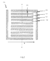
- FIG. 1 is a cross-sectional view illustrating a fuel cell disclosed by Patent Document 1.
- the fuel cell includes MEA I and a pair of air electrode separator 2 and fuel electrode separator 3 between which MEA I is held.
- Air electrode separator 2 includes oxidizing gas flow channels 8
- fuel electrode separator 3 includes fuel gas flow channels 16.
- oxidizing gas and fuel gas flow in opposite directions.
- coolant flow channel 15 is provided above oxidizing gas outlet 10, thereby cooling the oxidizing gas flowing near gas outlet 10. Cooling the oxidizing gas flowing near gas outlet 10 causes condensation of moisture in the gas, whereby water in the oxidizing gas can be recovered. In this way water generated in the fuel cell can be retained in the fuel cell.
- the MEA shows a non-uniform water distribution because only a small amount of water moves into the fuel gas flow channel from the oxidizing gas flow channel. The reason for this will be described below.
- the oxidizing gas has a higher water content than the fuel gas.
- the inventors established that water transport from the oxidizing gas flow channel to the fuel gas flow channel is promoted by employing different cross-sectional areas for adjacent oxidizing gas flow channels.
- the inventors conducted further studies to complete the present invention.
- the present invention relates to fuel cells described below.
- a fuel cell according to the present invention can circulate water within the cell even when less- or non-humidified reaction gases are supplied, thus allowing a sufficient amount of water to be retained in the fuel cell and achieving a uniform water distribution even when such reaction gases are supplied.
- the fuel cell offers high MEA durability and high output density.
- a fuel cell according to the present invention includes an MEA and a pair of separators A and B between which the MEA is held. In the fuel cell, less- or non-humidified reaction gases are supplied.
- MEA Membrane electrode assembly
- the MEA includes a polymer electrolyte membrane and a pair of catalyst electrodes (fuel electrode and air electrode) between which the polymer electrolyte membrane is held.
- the air electrode preferably includes an air electrode catalyst layer which contacts the polymer electrode membrane, and an air electrode gas diffusion layer stacked on the air electrode catalyst layer.
- the fuel cell preferably includes a fuel electrode catalyst layer which contacts the polymer electrolyte membrane, and a fuel electrode gas diffusion layer stacked on the fuel electrode catalyst layer.
- the polymer electrolyte membrane is a polymer membrane which selectively transports protons in a humidified state.
- Materials for the polymer electrode membrane are not specifically limited as long as they selectively transport protons; examples of such materials include fluoropolymer electrolyte membranes and hydrocarbon polymer electrolyte membranes.
- fluoropolymer electrolyte membrane products include Nafion ® (DuPont), Flemion ® (Asahi Glass, Co., Ltd.), Aciplex ® (Asahi Kasei Corporation), and GORE-SELECT ® (Japan Gore-Tex Inc.)
- the air electrode catalyst layer includes a catalyst which promotes a redox reaction between hydrogen and oxygen.
- Materials for the air electrode catalyst layer are not specifically limited as long as they are conductive as well as are capable of catalyzing a redox reaction between hydrogen and oxygen.
- the air electrode catalyst layer includes as a catalyst platinum, platinum-cobalt alloy, or platinum-cobalt-nickel alloy, etc.
- the fuel electrode catalyst layer includes a catalyst which promotes a hydrogen oxidization reaction.
- Materials for the fuel electrode catalyst layer are not specifically limited as long as they are electrically conductive as well as are capable of catalyzing a hydrogen oxidation reaction.
- the fuel electrode catalyst layer includes as a catalyst platinum or platinum-ruthenium alloy, etc.
- the air electrode catalyst layer and fuel electrode catalyst layer are prepared as follows: carbon fine particles (e.g., acetylene black, Ketjen black or Vulcan fine particles) bearing any of the above catalysts, a proton-conductive electrolyte, and a water-repellent resin (e.g., polytetrafluoroethylene (PTFE)) are mixed together, followed by application of the obtained mixture over the polymer electrolyte membrane.
- carbon fine particles e.g., acetylene black, Ketjen black or Vulcan fine particles bearing any of the above catalysts
- a proton-conductive electrolyte e.g., a proton-conductive electrolyte
- a water-repellent resin e.g., polytetrafluoroethylene (PTFE)
- the gas diffusion layers are porous conductive layers placed farthest away from the MEA (they contact the respective separators). Materials for the gas diffusion layers are not specifically limited as long as they are conductive as well as are capable of diffusing reaction gases.
- the gas diffusion layer may include a gas diffusion base layer and a carbon coat layer.
- the gas diffusion base layer diffuses the gas supplied from the separator side into the catalyst layer, and the carbon coat layer improves the contact reliability between the gas diffusion layer and catalyst layer.
- the gas diffusion layers may be prepared by heat-pressing onto the catalyst layer surface a carbon cloth made of carbon fibers having water-repellent resin such as PTFE or fibrous carbon.
- the separators are conductive plates having thereon multiple gas flow channels defined by ribs. Reaction gases (oxidizing gas and fuel gas) are supplied to the respective electrodes via the gas flow channels.
- the separator may be fabricated by engraving the surface of a carbon plate with gas flow channels (see FIG. 3A ). Alternatively, the separator may be fabricated by stamping a conductive plate for defining gas flow channels (see FIG. 4 ).
- the conductive plate may be made of either carbon or metal. Separator fabricated by stamping a metal plate is also referred to as metal separator.
- a separator manufactured by stamping of a conductive plate includes a waveform cross section of uniform thickness and flow channels defined on both sides of the separator.
- a first surface of the separator with a waveform cross section includes alternating grooves and ribs formed thereon and, therefore, the opposite surface of the separator from the first surface includes alternating ribs and grooves.
- the grooves of the first surface correspond to the ribs of the opposite surface and the ribs of the first surface correspond to the grooves of the opposite surface.
- a feature of the present invention lies in the separator structure.
- separator A and ii) separator B will be described.
- Separator A is a conductive plate which includes multiple gas flow channels defined by ribs.
- a fuel cell according to the present invention is characterized in that separator A includes gas flow channels with a large cross sectional area, i.e., large volume (hereinafter “first gas flow channels a1”) and gas flow channels with a small cross sectional area, i.e., small volume (hereinafter “second gas flow channels a2").
- first gas flow channels a1 gas flow channels with a large cross sectional area
- second gas flow channels a2 gas flow channels with a small cross sectional area
- cross section refers to a transverse section of a gas flow channel which is perpendicular to the channel length.
- the cross sectional area ratio between first gas flow channel a1 and second gas flow channel a2 is preferably 5:1 to 9:1.
- First gas flow channels a1 and second gas flow channels a2 preferably run in parallel to each other. Moreover, preferably, first gas flow channels a1 and second gas flow channels a2 are alternately arranged. The interval between first gas flow channel a1 and second gas flow channel a2 is preferably 0.7-1.3mm.
- Adjustment of the gas flow channel volume may be accomplished by adjusting the gas flow channel width or gas flow channel depth, preferably gas flow channel depth.
- First gas flow channel a1 is preferably 0.8-1.2mm in width and 0.3-0.8mm in depth.
- Second gas flow channel a2 is preferably 0.8-1.2mm in width and 0.06-0.1mm in depth.
- FIG. 2 illustrates an example where the volumes of gas flow channel of separator A are adjusted by adjusting their depths.
- FIG. 2 is a plan view of an example of separator A according to the present invention.
- separator A 120 includes first gas flow channels 121, second gas flow channels 122, and ribs 123 which define first and second gas flow channels 121 and 122.
- first and second gas flow channels 121 and 122 run in parallel to each other, and are alternately arranged.
- FIG. 3A is a cross-sectional view, cut along A-A line, of separator A 120 shown in FIG. 2 .
- FIG. 3B is an enlarged view of the dashed rectangular area of separator A 120 shown in FIG. 3A .
- depth 121d of first gas flow channel 121 is larger than depth 122d of second gas flow channel 122.
- first gas flow channel 121 is larger in cross sectional area than second gas flow channel 122. Therefore, first gas flow channel 121 is larger in volume than second gas flow channel 122.
- separator A is preferably an air electrode separator.
- gas flow channels in separator A are preferably are oxidizing gas flow channels through which oxidizing gas is supplied to the air electrode.
- separator A first gas flow channel a1
- second gas flow channel a2 are also referred to as “air electrode separator,” “first oxidizing gas flow channel” and “second oxidizing gas flow channel,” respectively.
- Separator B is a conductive plate which includes two or more gas flow channels defined by ribs.
- gas flow channels of separator B run in parallel with those of separator A. It is preferable that separator B be made of the same material as separator A.
- employing metal separators A and B offers advantages in the manufacturing process because one metal separator with a certain flow channel pattern may selectively serve as separator A or separator B.
- separator B includes first gas flow channels b1 and second gas flow channels b2 placed adjacent to first gas flow channels b1.
- first gas flow channels b1 and second gas flow channels b2 run in parallel to each other and are alternately arranged.
- First gas flow channels b1 may be identical in cross sectional area to second gas flow channels b2, but are preferably smaller in cross sectional area than second gas flow channels b2.
- the cross sectional area ratio between first gas flow channel b1 and second gas flow channel b2 is preferably 1:5 to 1:9.
- Adjustment of gas flow channel volume may be achieved by adjustment of the gas flow channel width or gas flow channel depth, preferably gas flow channel depth.
- First gas flow channel b1 is preferably 0.8-1.2mm in width and 0.06-0.1mm in depth.
- Second gas flow channel b2 is preferably 0.8-1.2mm in width and 0.3-0.8mm in depth.
- separator B is preferably a fuel electrode separator.
- gas flow channels in separator B are preferably fuel gas flow channels through which a fuel gas is supplied to the fuel electrode.
- separator B first gas flow channel b1" and “second gas flow channel b2” are also referred to as “fuel electrode separator,” “first fuel gas flow channel” and “second fuel gas flow channel,” respectively.
- oxidizing gas flow channels (separator A gas flow channels) and fuel gas flow channels (separator B gas flow channels)
- oxidizing gas flow channels and fuel gas flow channels be located directly opposite each other across the MEA. It is most preferable that first oxidizing gas flow channels be on the direct opposite side of the MEA from first fuel gas flow channels, and that second oxidizing gas flow channels be on the direct opposite side of the MEA from second fuel gas flow channels.
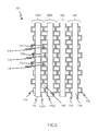
- FIG. 4 is a partial perspective view of a fuel cell according to the present invention, illustrating the positional relationship between oxidizing gas flow channels (separator A gas flow channels) and fuel gas flow channels (separator B gas flow channels).
- fuel cell 100 includes MEA 110, air electrode separator (separator A) 120, and fuel electrode separator (separator B) 130.
- MEA 110 includes polymer electrolyte membrane 111, air electrode catalyst layer 113, fuel electrode catalyst layer 115, air electrode gas diffusion layer 117, and fuel electrode gas diffusion layer 119.
- Air electrode separator 120 and fuel electrode separator 130 shown in FIG. 4 are separators having a waveform cross sections.
- Air electrode separator 120 includes first oxidizing gas flow channels 121 (first gas flow channels a1) and second oxidizing gas flow channels 122 (second gas flow channels a2).
- Fuel electrode separator 130 includes first fuel gas flow channels 131 (first gas flow channels b1) and second gas flow channels 132 (second gas flow channels b2).
- First oxidizing gas flow channels 121 are larger in cross sectional area than second oxidizing gas flow channels 122.
- First fuel gas flow channels 131 are smaller in cross sectional area than second fuel gas flow channels 132.
- arrow X indicates the direction in which oxidizing gas flows through an oxidizing gas flow channels
- arrow Y indicates the direction in which a fuel gas flows through fuel gas flow channels.
- the oxidizing gas and fuel gas flow in opposite directions in the flow channels.
- first oxidizing gas flow channels and second oxidizing gas flow channels which are smaller in volume than the first oxidizing gas flow channels are arranged alternately and in which oxidizing gas and fuel gas are made to flow in opposite directions in the gas flow channels, it is possible to promote transport of water, which has been generated during electricity generation of the fuel cell, from the oxidizing gas flow channels to the fuel gas flow channels. The mechanism of this will be described later.
- first oxidizing gas flow channels 121 are on the direct opposite side of the MEA from first fuel gas flow channels 131
- second oxidizing gas flow channels 122 are on the direct opposite side of the MEA from second fuel gas flow channels 132.
- the cross sectional area ratio between the second oxidizing gas flow channel and second fuel gas flow channel is preferably 1:5 to 1:9.
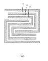
- the oxidizing gas flow channels may serpentine as shown in FIG. 5 .
- serpentine fuel gas flow channels When using serpentine oxidizing gas flow channels, it is preferable to form serpentine fuel gas flow channels correspondingly.
- a fuel cell stack may be manufactured by stacking fuel cells according to the present invention on top of each other.
- a fuel cell stack includes a cell stack consisting of fuel cells; current collectors; insulating plates; and end plates. The cell stack is sandwiched between the current collectors, insulating plates and end plates. The cell stack and the other members are fixed together with fixing rods.
- an air electrode separator and a fuel electrode separator which have a waveform cross section.
- FIG. 6 is a cross-sectional view of fuel cell stack 101 which includes an air electrode separator and a fuel electrode separator, both of which are separators with a waveform cross section.
- fuel cell 101X is placed adjacent to fuel cell 101Y.
- Fuel cells 100X and 100Y are electrically connected via air electrode separator 120X of fuel cell 100X and fuel electrode separator 130Y of fuel cell 100Y.
- first oxidizing gas flow channel 121 of air electrode separator 120X contacts the back surface of first fuel gas flow channel 131 of fuel electrode separator 130Y
- second oxidizing gas flow channel 122 of air electrode separator 120X contacts the back surface of second fuel gas flow channel 132 of fuel electrode separator 130Y.
- flow channels 140 of equal volume are formed between air electrode separator 120X and fuel electrode separator 130Y.
- flow channels 140 may serve as coolant flow channels.
- FIG. 7 is a cross-sectional view of fuel cell stack 102 consisting of stacked fuel cells each including fuel gas flow channels which are smaller in width than oxidizing gas flow channels.
- fuel cell stack 102 the same members as those of fuel cell stack 101 shown in FIG. 6 are given the same reference numerals without providing specific description.
- fuel gas flow channels 131' and 132' in fuel electrode separator 130' are smaller in width than oxidizing gas flow channels 121 and 122.
- the fuel gas flow channels are small in back surface area than the oxidizing gas flow channels, This configuration reduces the possible contact area variations between stacked fuel cells even when slight displacement occurs between the fuel cells in the fuel cell stack. Thus, it is possible to reduce generated electricity level unevenness due to fuel cell displacement in the fuel cell stack.
- a fuel cell according to the present invention is characterized in that it can retain therein a sufficient amount of water for high output density even when less- or non-humidified reaction gases are employed.
- a fuel cell according to the present invention offers high output density even when operated under a moderate-temperature, non-humidified condition or a high-temperature, less-humidified condition.
- moderate-temperature, non-humidified condition refers to an operation condition in which oxidizing gas to be supplied to the fuel cell is not humidified.
- the moderate-temperature, non-humidified condition refers to a condition in which the temperature of the fuel cell at which it generates electricity is 55°C to 75°C; the dew point of the oxidizing gas to be supplied to the fuel cell is 45°C or less, preferably -10°C to 45°C; and the dew point of the fuel gas to be supplied to the fuel cell is 50°C to 70°C. Dew point increases with increasing water content in the gas, and decreases with decreasing water content in the gas. Under such a moderate-temperature, non-humidified condition, the dew point of the oxidizing gas is generally at least 20°C lower than the dew point of the fuel gas.
- high-temperature, less-humidified condition refers to an operation condition in which the temperature of the fuel cell at which it generates electricity is 80°C to 100°C; the dew point of the oxidizing gas is 55°C to 75°C; and the dew point of the fuel gas is 50°C to 70°C. Under such a high-temperature, less-humidified condition, the difference in dew point between the oxidizing gas and fuel gas is generally 10°C or less.
- Fuel gas supplied to a fuel cell cogeneration system is generated by reforming a hydrocarbon gas using a reformer.
- Such a reformed gas has a dew point generally ranging from 50°C to 70°C.
- hydrogen molecules supplied to the fuel electrode diffuse out in the fuel electrode gas diffusion layer and then reach the fuel electrode catalyst layer, where they are dissociated into protons and electrodes.
- the protons move through the humidified polymer electrolyte membrane to the air electrode, whereas the electrons move through an external circuit to the air electrode.
- the electrons moving through the external circuit may be utilized as electric energy.
- the protons transported from the polymer electrolyte membrane, the electrons transported from the external circuit, and the oxygen molecules supplied to the air electrode react together to form water, which is converted into water vapor and diffuses out mainly in the oxidizing gas flow channels.
- a fuel cell according to the present invention is characterized in that it is capable of circulating water contained in the oxidizing gas throughout the cell.
- FIG. 8 is a cross-sectional view, cut along dashed line A, of fuel cell 100 shown in FIG. 4 .
- FIG. 8 illustrates a vertical section of second oxidizing flow channel 122 and a vertical section of second fuel gas flow channel 132. Arrows in the drawing indicates flow direction and the arrow size indicates flow amount.
- second oxidizing gas flow channels 122 are smaller in volume than second fuel gas flow channels 132 which are on the direct opposite side of MEA 110 from second oxidizing flow channels 122. Thus, a small quantity of oxidizing gas passes through second oxidizing gas flow channels 122.
- Second fuel gas flow channels 132 have a high volume; therefore, a large amount of fuel gas passes through second fuel gas flow channels 132. Moreover, because water generated during the operation of the fuel cell diffuses out mainly in the oxidizing gas flow channels as described above, the fuel gas passing through second fuel gas flow channels 132 contains a smaller amount of water. Thus, the water content in the fuel gas passing through second fuel gas flow channels 132 is small.
- the net result of the above is that the oxidizing gas passing through second oxidizing gas flow channel 122 has a higher water content than the fuel gas passing through second fuel gas flow channel 132. This water content difference promotes water transport from second oxidizing gas flow channel 122 to second fuel gas flow channel 132.
- the oxidizing gas receives water when passing through the oxidizing gas flow channels.
- the oxidizing gas has a maximum water content in the vicinity of oxidizing gas outlet 127.
- the fuel gas has a maximum hydrogen content in the vicinity of fuel gas inlet 135, because hydrogen molecules in the fuel gas are consumed while the fuel gas passes through the fuel gas flow channel.
- the water content difference between the oxidizing gas and fuel gas becomes most significant in the vicinity of oxidizing gas outlet 127 and fuel gas inlet 135 (see the dashed rectangular area in FIG. 8 ).
- water transport is most promoted from the vicinity of oxidizing gas flow outlet 127 to the vicinity of fuel gas flow inlet 135.
- Electricity generation decreases near oxidizing gas outlet 127 due to low oxygen level in the oxidizing gas. Reduced electricity generation hinders electro-osmotic water transport from the fuel electrode to the air electrode, whereby water transport from the second oxidizing gas flow channel to the second fuel gas flow channel is further promoted.
- the volumes of the first oxidizing gas flow channels are large enough to provide a sufficient amount of oxidizing gas to the fuel cell.
- FIG. 9A is a graph of humidity in oxidizing gas channel vs. depth of second oxidizing gas flow channel.
- the oxidizing gas flow channels showed a relative humidity of about 35% near the upstream end and showed a relative humidity of about 55% near the downstream end.
- the second oxidizing gas flow channels were 0.1mm in depth, the oxidizing gas flow channels showed a relative humidity of about 35% near the upstream end and showed a relative humidity of about 53% near the downstream end.
- the oxidizing gas flow channels When the second oxidizing gas flow channels were 0.02mm in depth, the oxidizing gas flow channels showed a relative humidity of about 37% near the upstream end and showed a relative humidity of about 51% near the downstream end. It was thus demonstrated that relative humidity variations across the oxidizing gas flow channel decrease with decreasing depth of the oxidizing gas flow channel.
- FIG. 9B is a graph of humidity in fuel gas channel vs. depth of second oxidizing gas flow channel.
- the fuel gas flow channels showed a relative humidity of about 42% near the upstream end and showed a relative humidity of about 37% near the downstream end, with a maximum relative humidity being about 52%.
- the second oxidizing gas flow channel was 0.1mm in depth, the fuel gas flow channels showed a relative humidity of about 43% near the upstream end and showed a relative humidity of about 39% near the downstream end, with a maximum relativity humidity being about 53%.
- the fuel gas flow channels showed a relative humidity of about 45% near the upstream end and showed a relative humidity of about 39% near the downstream end, with a maximum relative humidity being 53%. It was thus demonstrated that variations in relative humidity in the fuel gas flow channels decrease with decreasing depth of the oxidizing gas flow channels.
- the water distribution in the fuel cell becomes uniform as the depth of the oxidizing gas flow channels decreases.
- the second oxidizing gas flow channels are too shallow, it may result in reduced oxidizing gas amount in the oxidizing gas flow channels, which may lead to poor electricity generation efficiency.
- changes in proton conductivity of the polymer electrolyte membrane and generated voltage with changes in the second oxidizing gas flow channel depth were simulated.
- the simulation condition used for the first simulation above may be used.
- FIG. 10 is a graph of generated voltage and proton conductivity vs. depth of second oxidizing gas flow channel.
- the polymer electrolyte membrane showed a maximum proton conductivity when the second oxidizing gas flow channels were 0.06mm in depth.
- the generated voltage level was kept high within the second oxidizing gas flow channel depth range of 0.06-0.1 mm, with the voltage peak at the 0.08mm depth. This graph thus suggests that an optimal second oxidizing gas flow channel depth ranges from 0.06-0.1mm.
- second oxidizing gas flow channels which are smaller in volume than second fuel gas flow channels, are placed on the direct opposite side of the MEA from the second fuel gas flow channels, as well as oxidizing gas and fuel gas are made to flow in opposite directions.
- water transport from the oxidizing gas flow channels to the fuel gas flow channels can be promoted. It is thus made possible for the fuel cell to retain a sufficient amount of water for high output density and high MEA durability even when employing less- or non-humidified reaction gases.
- Fuel cells according to the present invention are useful as polymer electrolyte fuel cells which use less- or non-humidified reaction gases.
Applications Claiming Priority (2)
| Application Number | Priority Date | Filing Date | Title |
|---|---|---|---|
| JP2008307651 | 2008-12-02 | ||
| PCT/JP2009/006094 WO2010064366A1 (fr) | 2008-12-02 | 2009-11-13 | Pile à combustible |
Publications (3)
| Publication Number | Publication Date |
|---|---|
| EP2362470A1 true EP2362470A1 (fr) | 2011-08-31 |
| EP2362470A4 EP2362470A4 (fr) | 2012-09-12 |
| EP2362470B1 EP2362470B1 (fr) | 2014-05-21 |
Family
ID=42233025
Family Applications (1)
| Application Number | Title | Priority Date | Filing Date |
|---|---|---|---|
| EP09830137.7A Active EP2362470B1 (fr) | 2008-12-02 | 2009-11-13 | Pile à combustible |
Country Status (5)
| Country | Link |
|---|---|
| US (1) | US9153825B2 (fr) |
| EP (1) | EP2362470B1 (fr) |
| JP (1) | JP4559539B2 (fr) |
| CN (1) | CN101878557A (fr) |
| WO (1) | WO2010064366A1 (fr) |
Families Citing this family (9)
| Publication number | Priority date | Publication date | Assignee | Title |
|---|---|---|---|---|
| JP5560728B2 (ja) * | 2010-01-19 | 2014-07-30 | トヨタ車体株式会社 | 燃料電池 |
| JP4868094B1 (ja) * | 2011-01-28 | 2012-02-01 | トヨタ自動車株式会社 | 燃料電池システム |
| WO2012101818A1 (fr) * | 2011-01-28 | 2012-08-02 | トヨタ自動車株式会社 | Système de pile à combustible |
| JP5802648B2 (ja) * | 2012-12-25 | 2015-10-28 | 本田技研工業株式会社 | 燃料電池 |
| JP6155711B2 (ja) * | 2013-03-11 | 2017-07-05 | 日産自動車株式会社 | 燃料電池 |
| JP6090091B2 (ja) * | 2013-10-01 | 2017-03-08 | トヨタ自動車株式会社 | 燃料電池 |
| JP7021551B2 (ja) * | 2018-02-08 | 2022-02-17 | トヨタ自動車株式会社 | 燃料電池スタック |
| JP7088045B2 (ja) * | 2019-01-22 | 2022-06-21 | トヨタ自動車株式会社 | 燃料電池スタック |
| JP6818920B2 (ja) * | 2020-02-12 | 2021-01-27 | 株式会社東芝 | 電気化学反応装置 |
Citations (2)
| Publication number | Priority date | Publication date | Assignee | Title |
|---|---|---|---|---|
| US20040058218A1 (en) * | 2002-09-20 | 2004-03-25 | Ballard Power Systems Inc. | Flow fields with capillarity for solid polymer electrolyte fuel cells |
| US20060046125A1 (en) * | 2004-08-25 | 2006-03-02 | Yeh-Hung Lai | Electrochemical fuel cell elements having improved compression over channels |
Family Cites Families (11)
| Publication number | Priority date | Publication date | Assignee | Title |
|---|---|---|---|---|
| US5773160A (en) * | 1994-06-24 | 1998-06-30 | Ballard Power Systems Inc. | Electrochemical fuel cell stack with concurrent flow of coolant and oxidant streams and countercurrent flow of fuel and oxidant streams |
| JP2001006698A (ja) | 1999-06-23 | 2001-01-12 | Fuji Electric Co Ltd | 固体高分子電解質型燃料電池と同燃料電池用拡散層の製造方法 |
| JP3571696B2 (ja) * | 2001-01-30 | 2004-09-29 | 本田技研工業株式会社 | 燃料電池及び燃料電池スタック |
| JP4344484B2 (ja) * | 2001-03-06 | 2009-10-14 | 本田技研工業株式会社 | 固体高分子型セルアセンブリ |
| JP3736475B2 (ja) | 2002-02-26 | 2006-01-18 | 日産自動車株式会社 | 燃料電池 |
| JP2004146230A (ja) * | 2002-10-25 | 2004-05-20 | Matsushita Electric Ind Co Ltd | 燃料電池のセパレータ |
| JP2005032578A (ja) | 2003-07-04 | 2005-02-03 | Nissan Motor Co Ltd | 燃料電池用セパレータ、燃料電池および燃料電池自動車 |
| JP2005174648A (ja) | 2003-12-09 | 2005-06-30 | Nissan Motor Co Ltd | 燃料電池 |
| JP2005251699A (ja) | 2004-03-08 | 2005-09-15 | Mitsubishi Electric Corp | 燃料電池 |
| JP2006114387A (ja) | 2004-10-15 | 2006-04-27 | Toyota Motor Corp | 燃料電池 |
| JP4732296B2 (ja) * | 2005-11-16 | 2011-07-27 | シャープ株式会社 | 燃料電池 |
-
2009
- 2009-11-13 US US12/747,808 patent/US9153825B2/en active Active
- 2009-11-13 WO PCT/JP2009/006094 patent/WO2010064366A1/fr active Application Filing
- 2009-11-13 JP JP2010511441A patent/JP4559539B2/ja active Active
- 2009-11-13 CN CN2009801011104A patent/CN101878557A/zh active Pending
- 2009-11-13 EP EP09830137.7A patent/EP2362470B1/fr active Active
Patent Citations (2)
| Publication number | Priority date | Publication date | Assignee | Title |
|---|---|---|---|---|
| US20040058218A1 (en) * | 2002-09-20 | 2004-03-25 | Ballard Power Systems Inc. | Flow fields with capillarity for solid polymer electrolyte fuel cells |
| US20060046125A1 (en) * | 2004-08-25 | 2006-03-02 | Yeh-Hung Lai | Electrochemical fuel cell elements having improved compression over channels |
Non-Patent Citations (1)
| Title |
|---|
| See also references of WO2010064366A1 * |
Also Published As
| Publication number | Publication date |
|---|---|
| JPWO2010064366A1 (ja) | 2012-05-10 |
| CN101878557A (zh) | 2010-11-03 |
| US20100285384A1 (en) | 2010-11-11 |
| WO2010064366A1 (fr) | 2010-06-10 |
| EP2362470A4 (fr) | 2012-09-12 |
| EP2362470B1 (fr) | 2014-05-21 |
| JP4559539B2 (ja) | 2010-10-06 |
| US9153825B2 (en) | 2015-10-06 |
Similar Documents
| Publication | Publication Date | Title |
|---|---|---|
| EP2362470B1 (fr) | Pile à combustible | |
| US8367270B2 (en) | Flow field plate arrangement for a fuel cell | |
| US7745063B2 (en) | Fuel cell stack | |
| US6303245B1 (en) | Fuel cell channeled distribution of hydration water | |
| US20110207018A1 (en) | Solid polymer fuel cell | |
| JP2007200864A (ja) | バイポーラプレートおよび燃料電池 | |
| JP2005340173A (ja) | 燃料電池スタック | |
| US8546038B2 (en) | Fuel cell separator having reactant gas channels with different cross sections and fuel cell comprising the same | |
| US8221932B2 (en) | Fuel cell | |
| JP2001006708A (ja) | 固体高分子型燃料電池 | |
| US8546037B2 (en) | Fuel cell separator having reactant gas channels with different cross sections and fuel cell comprising the same | |
| US20050255371A1 (en) | Fuel cell | |
| EP1677378A1 (fr) | Pile à combustible et batterie de piles à combustible | |
| JP2004030959A (ja) | ガス拡散部材、ガス拡散電極および燃料電池 | |
| US8084163B2 (en) | Fuel cell | |
| EP2405515B1 (fr) | Séparateur pour pile à combustible et pile à combustible le comprenant | |
| WO2011059087A1 (fr) | Pile à combustible et véhicule équipé d'une pile à combustible | |
| JP2000251901A (ja) | 燃料電池用セル及びこれを用いた燃料電池 | |
| US8568941B2 (en) | Fuel cell separator and fuel cell including same | |
| JP2005142027A (ja) | 高分子電解質型燃料電池 | |
| JP2005327613A (ja) | 燃料電池 | |
| JP2014099375A (ja) | 燃料電池システム、および燃料電池システムの運転方法 |
Legal Events
| Date | Code | Title | Description |
|---|---|---|---|
| PUAI | Public reference made under article 153(3) epc to a published international application that has entered the european phase |
Free format text: ORIGINAL CODE: 0009012 |
|
| 17P | Request for examination filed |
Effective date: 20100628 |
|
| AK | Designated contracting states |
Kind code of ref document: A1 Designated state(s): AT BE BG CH CY CZ DE DK EE ES FI FR GB GR HR HU IE IS IT LI LT LU LV MC MK MT NL NO PL PT RO SE SI SK SM TR |
|
| DAX | Request for extension of the european patent (deleted) | ||
| A4 | Supplementary search report drawn up and despatched |
Effective date: 20120813 |
|
| RIC1 | Information provided on ipc code assigned before grant |
Ipc: H01M 8/10 20060101ALI20120807BHEP Ipc: H01M 8/02 20060101AFI20120807BHEP |
|
| 17Q | First examination report despatched |
Effective date: 20130418 |
|
| GRAP | Despatch of communication of intention to grant a patent |
Free format text: ORIGINAL CODE: EPIDOSNIGR1 |
|
| INTG | Intention to grant announced |
Effective date: 20131217 |
|
| GRAS | Grant fee paid |
Free format text: ORIGINAL CODE: EPIDOSNIGR3 |
|
| GRAA | (expected) grant |
Free format text: ORIGINAL CODE: 0009210 |
|
| AK | Designated contracting states |
Kind code of ref document: B1 Designated state(s): AT BE BG CH CY CZ DE DK EE ES FI FR GB GR HR HU IE IS IT LI LT LU LV MC MK MT NL NO PL PT RO SE SI SK SM TR |
|
| REG | Reference to a national code |
Ref country code: GB Ref legal event code: FG4D |
|
| REG | Reference to a national code |
Ref country code: CH Ref legal event code: EP |
|
| REG | Reference to a national code |
Ref country code: AT Ref legal event code: REF Ref document number: 670002 Country of ref document: AT Kind code of ref document: T Effective date: 20140615 |
|
| REG | Reference to a national code |
Ref country code: IE Ref legal event code: FG4D |
|
| REG | Reference to a national code |
Ref country code: DE Ref legal event code: R096 Ref document number: 602009024333 Country of ref document: DE Effective date: 20140710 |
|
| REG | Reference to a national code |
Ref country code: NL Ref legal event code: VDEP Effective date: 20140521 Ref country code: AT Ref legal event code: MK05 Ref document number: 670002 Country of ref document: AT Kind code of ref document: T Effective date: 20140521 |
|
| REG | Reference to a national code |
Ref country code: LT Ref legal event code: MG4D |
|
| PG25 | Lapsed in a contracting state [announced via postgrant information from national office to epo] |
Ref country code: IS Free format text: LAPSE BECAUSE OF FAILURE TO SUBMIT A TRANSLATION OF THE DESCRIPTION OR TO PAY THE FEE WITHIN THE PRESCRIBED TIME-LIMIT Effective date: 20140921 Ref country code: LT Free format text: LAPSE BECAUSE OF FAILURE TO SUBMIT A TRANSLATION OF THE DESCRIPTION OR TO PAY THE FEE WITHIN THE PRESCRIBED TIME-LIMIT Effective date: 20140521 Ref country code: GR Free format text: LAPSE BECAUSE OF FAILURE TO SUBMIT A TRANSLATION OF THE DESCRIPTION OR TO PAY THE FEE WITHIN THE PRESCRIBED TIME-LIMIT Effective date: 20140822 Ref country code: FI Free format text: LAPSE BECAUSE OF FAILURE TO SUBMIT A TRANSLATION OF THE DESCRIPTION OR TO PAY THE FEE WITHIN THE PRESCRIBED TIME-LIMIT Effective date: 20140521 Ref country code: NO Free format text: LAPSE BECAUSE OF FAILURE TO SUBMIT A TRANSLATION OF THE DESCRIPTION OR TO PAY THE FEE WITHIN THE PRESCRIBED TIME-LIMIT Effective date: 20140821 |
|
| PG25 | Lapsed in a contracting state [announced via postgrant information from national office to epo] |
Ref country code: PL Free format text: LAPSE BECAUSE OF FAILURE TO SUBMIT A TRANSLATION OF THE DESCRIPTION OR TO PAY THE FEE WITHIN THE PRESCRIBED TIME-LIMIT Effective date: 20140521 Ref country code: AT Free format text: LAPSE BECAUSE OF FAILURE TO SUBMIT A TRANSLATION OF THE DESCRIPTION OR TO PAY THE FEE WITHIN THE PRESCRIBED TIME-LIMIT Effective date: 20140521 Ref country code: HR Free format text: LAPSE BECAUSE OF FAILURE TO SUBMIT A TRANSLATION OF THE DESCRIPTION OR TO PAY THE FEE WITHIN THE PRESCRIBED TIME-LIMIT Effective date: 20140521 Ref country code: LV Free format text: LAPSE BECAUSE OF FAILURE TO SUBMIT A TRANSLATION OF THE DESCRIPTION OR TO PAY THE FEE WITHIN THE PRESCRIBED TIME-LIMIT Effective date: 20140521 Ref country code: ES Free format text: LAPSE BECAUSE OF FAILURE TO SUBMIT A TRANSLATION OF THE DESCRIPTION OR TO PAY THE FEE WITHIN THE PRESCRIBED TIME-LIMIT Effective date: 20140521 Ref country code: SE Free format text: LAPSE BECAUSE OF FAILURE TO SUBMIT A TRANSLATION OF THE DESCRIPTION OR TO PAY THE FEE WITHIN THE PRESCRIBED TIME-LIMIT Effective date: 20140521 |
|
| PG25 | Lapsed in a contracting state [announced via postgrant information from national office to epo] |
Ref country code: PT Free format text: LAPSE BECAUSE OF FAILURE TO SUBMIT A TRANSLATION OF THE DESCRIPTION OR TO PAY THE FEE WITHIN THE PRESCRIBED TIME-LIMIT Effective date: 20140922 |
|
| PG25 | Lapsed in a contracting state [announced via postgrant information from national office to epo] |
Ref country code: CZ Free format text: LAPSE BECAUSE OF FAILURE TO SUBMIT A TRANSLATION OF THE DESCRIPTION OR TO PAY THE FEE WITHIN THE PRESCRIBED TIME-LIMIT Effective date: 20140521 Ref country code: RO Free format text: LAPSE BECAUSE OF FAILURE TO SUBMIT A TRANSLATION OF THE DESCRIPTION OR TO PAY THE FEE WITHIN THE PRESCRIBED TIME-LIMIT Effective date: 20140521 Ref country code: SK Free format text: LAPSE BECAUSE OF FAILURE TO SUBMIT A TRANSLATION OF THE DESCRIPTION OR TO PAY THE FEE WITHIN THE PRESCRIBED TIME-LIMIT Effective date: 20140521 Ref country code: DK Free format text: LAPSE BECAUSE OF FAILURE TO SUBMIT A TRANSLATION OF THE DESCRIPTION OR TO PAY THE FEE WITHIN THE PRESCRIBED TIME-LIMIT Effective date: 20140521 Ref country code: EE Free format text: LAPSE BECAUSE OF FAILURE TO SUBMIT A TRANSLATION OF THE DESCRIPTION OR TO PAY THE FEE WITHIN THE PRESCRIBED TIME-LIMIT Effective date: 20140521 Ref country code: BE Free format text: LAPSE BECAUSE OF FAILURE TO SUBMIT A TRANSLATION OF THE DESCRIPTION OR TO PAY THE FEE WITHIN THE PRESCRIBED TIME-LIMIT Effective date: 20140521 |
|
| REG | Reference to a national code |
Ref country code: DE Ref legal event code: R097 Ref document number: 602009024333 Country of ref document: DE |
|
| PG25 | Lapsed in a contracting state [announced via postgrant information from national office to epo] |
Ref country code: NL Free format text: LAPSE BECAUSE OF FAILURE TO SUBMIT A TRANSLATION OF THE DESCRIPTION OR TO PAY THE FEE WITHIN THE PRESCRIBED TIME-LIMIT Effective date: 20140521 |
|
| PLBE | No opposition filed within time limit |
Free format text: ORIGINAL CODE: 0009261 |
|
| STAA | Information on the status of an ep patent application or granted ep patent |
Free format text: STATUS: NO OPPOSITION FILED WITHIN TIME LIMIT |
|
| 26N | No opposition filed |
Effective date: 20150224 |
|
| PG25 | Lapsed in a contracting state [announced via postgrant information from national office to epo] |
Ref country code: IT Free format text: LAPSE BECAUSE OF FAILURE TO SUBMIT A TRANSLATION OF THE DESCRIPTION OR TO PAY THE FEE WITHIN THE PRESCRIBED TIME-LIMIT Effective date: 20140521 |
|
| REG | Reference to a national code |
Ref country code: DE Ref legal event code: R097 Ref document number: 602009024333 Country of ref document: DE Effective date: 20150224 |
|
| PG25 | Lapsed in a contracting state [announced via postgrant information from national office to epo] |
Ref country code: MC Free format text: LAPSE BECAUSE OF FAILURE TO SUBMIT A TRANSLATION OF THE DESCRIPTION OR TO PAY THE FEE WITHIN THE PRESCRIBED TIME-LIMIT Effective date: 20140521 Ref country code: LU Free format text: LAPSE BECAUSE OF FAILURE TO SUBMIT A TRANSLATION OF THE DESCRIPTION OR TO PAY THE FEE WITHIN THE PRESCRIBED TIME-LIMIT Effective date: 20141113 |
|
| REG | Reference to a national code |
Ref country code: CH Ref legal event code: PL |
|
| PG25 | Lapsed in a contracting state [announced via postgrant information from national office to epo] |
Ref country code: SI Free format text: LAPSE BECAUSE OF FAILURE TO SUBMIT A TRANSLATION OF THE DESCRIPTION OR TO PAY THE FEE WITHIN THE PRESCRIBED TIME-LIMIT Effective date: 20140521 Ref country code: LI Free format text: LAPSE BECAUSE OF NON-PAYMENT OF DUE FEES Effective date: 20141130 Ref country code: CH Free format text: LAPSE BECAUSE OF NON-PAYMENT OF DUE FEES Effective date: 20141130 |
|
| REG | Reference to a national code |
Ref country code: IE Ref legal event code: MM4A |
|
| REG | Reference to a national code |
Ref country code: FR Ref legal event code: ST Effective date: 20150731 |
|
| PG25 | Lapsed in a contracting state [announced via postgrant information from national office to epo] |
Ref country code: IE Free format text: LAPSE BECAUSE OF NON-PAYMENT OF DUE FEES Effective date: 20141113 |
|
| PG25 | Lapsed in a contracting state [announced via postgrant information from national office to epo] |
Ref country code: FR Free format text: LAPSE BECAUSE OF NON-PAYMENT OF DUE FEES Effective date: 20141201 |
|
| PG25 | Lapsed in a contracting state [announced via postgrant information from national office to epo] |
Ref country code: SM Free format text: LAPSE BECAUSE OF FAILURE TO SUBMIT A TRANSLATION OF THE DESCRIPTION OR TO PAY THE FEE WITHIN THE PRESCRIBED TIME-LIMIT Effective date: 20140521 |
|
| PG25 | Lapsed in a contracting state [announced via postgrant information from national office to epo] |
Ref country code: BG Free format text: LAPSE BECAUSE OF FAILURE TO SUBMIT A TRANSLATION OF THE DESCRIPTION OR TO PAY THE FEE WITHIN THE PRESCRIBED TIME-LIMIT Effective date: 20140521 Ref country code: CY Free format text: LAPSE BECAUSE OF FAILURE TO SUBMIT A TRANSLATION OF THE DESCRIPTION OR TO PAY THE FEE WITHIN THE PRESCRIBED TIME-LIMIT Effective date: 20140521 |
|
| PG25 | Lapsed in a contracting state [announced via postgrant information from national office to epo] |
Ref country code: TR Free format text: LAPSE BECAUSE OF FAILURE TO SUBMIT A TRANSLATION OF THE DESCRIPTION OR TO PAY THE FEE WITHIN THE PRESCRIBED TIME-LIMIT Effective date: 20140521 Ref country code: MT Free format text: LAPSE BECAUSE OF FAILURE TO SUBMIT A TRANSLATION OF THE DESCRIPTION OR TO PAY THE FEE WITHIN THE PRESCRIBED TIME-LIMIT Effective date: 20140521 Ref country code: HU Free format text: LAPSE BECAUSE OF FAILURE TO SUBMIT A TRANSLATION OF THE DESCRIPTION OR TO PAY THE FEE WITHIN THE PRESCRIBED TIME-LIMIT; INVALID AB INITIO Effective date: 20091113 |
|
| PG25 | Lapsed in a contracting state [announced via postgrant information from national office to epo] |
Ref country code: MK Free format text: LAPSE BECAUSE OF FAILURE TO SUBMIT A TRANSLATION OF THE DESCRIPTION OR TO PAY THE FEE WITHIN THE PRESCRIBED TIME-LIMIT Effective date: 20140521 |
|
| PGFP | Annual fee paid to national office [announced via postgrant information from national office to epo] |
Ref country code: GB Payment date: 20231123 Year of fee payment: 15 |
|
| PGFP | Annual fee paid to national office [announced via postgrant information from national office to epo] |
Ref country code: DE Payment date: 20231121 Year of fee payment: 15 |