EP2360764A1 - Système de génération d'énergie mcfc et son procédé de fonctionnement - Google Patents
Système de génération d'énergie mcfc et son procédé de fonctionnement Download PDFInfo
- Publication number
- EP2360764A1 EP2360764A1 EP09827530A EP09827530A EP2360764A1 EP 2360764 A1 EP2360764 A1 EP 2360764A1 EP 09827530 A EP09827530 A EP 09827530A EP 09827530 A EP09827530 A EP 09827530A EP 2360764 A1 EP2360764 A1 EP 2360764A1
- Authority
- EP
- European Patent Office
- Prior art keywords
- gas
- power generation
- cathode
- exhaust
- fuel
- Prior art date
- Legal status (The legal status is an assumption and is not a legal conclusion. Google has not performed a legal analysis and makes no representation as to the accuracy of the status listed.)
- Withdrawn
Links
Images


Classifications
-
- H—ELECTRICITY
- H01—ELECTRIC ELEMENTS
- H01M—PROCESSES OR MEANS, e.g. BATTERIES, FOR THE DIRECT CONVERSION OF CHEMICAL ENERGY INTO ELECTRICAL ENERGY
- H01M8/00—Fuel cells; Manufacture thereof
- H01M8/14—Fuel cells with fused electrolytes
-
- H—ELECTRICITY
- H01—ELECTRIC ELEMENTS
- H01M—PROCESSES OR MEANS, e.g. BATTERIES, FOR THE DIRECT CONVERSION OF CHEMICAL ENERGY INTO ELECTRICAL ENERGY
- H01M8/00—Fuel cells; Manufacture thereof
- H01M8/04—Auxiliary arrangements, e.g. for control of pressure or for circulation of fluids
- H01M8/04082—Arrangements for control of reactant parameters, e.g. pressure or concentration
- H01M8/04089—Arrangements for control of reactant parameters, e.g. pressure or concentration of gaseous reactants
- H01M8/04111—Arrangements for control of reactant parameters, e.g. pressure or concentration of gaseous reactants using a compressor turbine assembly
-
- H—ELECTRICITY
- H01—ELECTRIC ELEMENTS
- H01M—PROCESSES OR MEANS, e.g. BATTERIES, FOR THE DIRECT CONVERSION OF CHEMICAL ENERGY INTO ELECTRICAL ENERGY
- H01M8/00—Fuel cells; Manufacture thereof
- H01M8/04—Auxiliary arrangements, e.g. for control of pressure or for circulation of fluids
-
- H—ELECTRICITY
- H01—ELECTRIC ELEMENTS
- H01M—PROCESSES OR MEANS, e.g. BATTERIES, FOR THE DIRECT CONVERSION OF CHEMICAL ENERGY INTO ELECTRICAL ENERGY
- H01M8/00—Fuel cells; Manufacture thereof
- H01M8/04—Auxiliary arrangements, e.g. for control of pressure or for circulation of fluids
- H01M8/04007—Auxiliary arrangements, e.g. for control of pressure or for circulation of fluids related to heat exchange
- H01M8/04014—Heat exchange using gaseous fluids; Heat exchange by combustion of reactants
-
- H—ELECTRICITY
- H01—ELECTRIC ELEMENTS
- H01M—PROCESSES OR MEANS, e.g. BATTERIES, FOR THE DIRECT CONVERSION OF CHEMICAL ENERGY INTO ELECTRICAL ENERGY
- H01M8/00—Fuel cells; Manufacture thereof
- H01M8/04—Auxiliary arrangements, e.g. for control of pressure or for circulation of fluids
- H01M8/04082—Arrangements for control of reactant parameters, e.g. pressure or concentration
- H01M8/04089—Arrangements for control of reactant parameters, e.g. pressure or concentration of gaseous reactants
- H01M8/04097—Arrangements for control of reactant parameters, e.g. pressure or concentration of gaseous reactants with recycling of the reactants
-
- H—ELECTRICITY
- H01—ELECTRIC ELEMENTS
- H01M—PROCESSES OR MEANS, e.g. BATTERIES, FOR THE DIRECT CONVERSION OF CHEMICAL ENERGY INTO ELECTRICAL ENERGY
- H01M8/00—Fuel cells; Manufacture thereof
- H01M8/06—Combination of fuel cells with means for production of reactants or for treatment of residues
- H01M8/0606—Combination of fuel cells with means for production of reactants or for treatment of residues with means for production of gaseous reactants
- H01M8/0612—Combination of fuel cells with means for production of reactants or for treatment of residues with means for production of gaseous reactants from carbon-containing material
-
- H—ELECTRICITY
- H01—ELECTRIC ELEMENTS
- H01M—PROCESSES OR MEANS, e.g. BATTERIES, FOR THE DIRECT CONVERSION OF CHEMICAL ENERGY INTO ELECTRICAL ENERGY
- H01M8/00—Fuel cells; Manufacture thereof
- H01M8/06—Combination of fuel cells with means for production of reactants or for treatment of residues
- H01M8/0662—Treatment of gaseous reactants or gaseous residues, e.g. cleaning
- H01M8/0668—Removal of carbon monoxide or carbon dioxide
-
- H—ELECTRICITY
- H01—ELECTRIC ELEMENTS
- H01M—PROCESSES OR MEANS, e.g. BATTERIES, FOR THE DIRECT CONVERSION OF CHEMICAL ENERGY INTO ELECTRICAL ENERGY
- H01M8/00—Fuel cells; Manufacture thereof
- H01M8/14—Fuel cells with fused electrolytes
- H01M2008/147—Fuel cells with molten carbonates
-
- H—ELECTRICITY
- H01—ELECTRIC ELEMENTS
- H01M—PROCESSES OR MEANS, e.g. BATTERIES, FOR THE DIRECT CONVERSION OF CHEMICAL ENERGY INTO ELECTRICAL ENERGY
- H01M8/00—Fuel cells; Manufacture thereof
- H01M8/04—Auxiliary arrangements, e.g. for control of pressure or for circulation of fluids
- H01M8/04082—Arrangements for control of reactant parameters, e.g. pressure or concentration
- H01M8/04089—Arrangements for control of reactant parameters, e.g. pressure or concentration of gaseous reactants
- H01M8/04119—Arrangements for control of reactant parameters, e.g. pressure or concentration of gaseous reactants with simultaneous supply or evacuation of electrolyte; Humidifying or dehumidifying
- H01M8/04126—Humidifying
- H01M8/04141—Humidifying by water containing exhaust gases
-
- H—ELECTRICITY
- H01—ELECTRIC ELEMENTS
- H01M—PROCESSES OR MEANS, e.g. BATTERIES, FOR THE DIRECT CONVERSION OF CHEMICAL ENERGY INTO ELECTRICAL ENERGY
- H01M8/00—Fuel cells; Manufacture thereof
- H01M8/04—Auxiliary arrangements, e.g. for control of pressure or for circulation of fluids
- H01M8/04298—Processes for controlling fuel cells or fuel cell systems
- H01M8/04694—Processes for controlling fuel cells or fuel cell systems characterised by variables to be controlled
- H01M8/04701—Temperature
- H01M8/04708—Temperature of fuel cell reactants
-
- H—ELECTRICITY
- H01—ELECTRIC ELEMENTS
- H01M—PROCESSES OR MEANS, e.g. BATTERIES, FOR THE DIRECT CONVERSION OF CHEMICAL ENERGY INTO ELECTRICAL ENERGY
- H01M8/00—Fuel cells; Manufacture thereof
- H01M8/04—Auxiliary arrangements, e.g. for control of pressure or for circulation of fluids
- H01M8/04298—Processes for controlling fuel cells or fuel cell systems
- H01M8/04694—Processes for controlling fuel cells or fuel cell systems characterised by variables to be controlled
- H01M8/04701—Temperature
- H01M8/04731—Temperature of other components of a fuel cell or fuel cell stacks
-
- Y—GENERAL TAGGING OF NEW TECHNOLOGICAL DEVELOPMENTS; GENERAL TAGGING OF CROSS-SECTIONAL TECHNOLOGIES SPANNING OVER SEVERAL SECTIONS OF THE IPC; TECHNICAL SUBJECTS COVERED BY FORMER USPC CROSS-REFERENCE ART COLLECTIONS [XRACs] AND DIGESTS
- Y02—TECHNOLOGIES OR APPLICATIONS FOR MITIGATION OR ADAPTATION AGAINST CLIMATE CHANGE
- Y02E—REDUCTION OF GREENHOUSE GAS [GHG] EMISSIONS, RELATED TO ENERGY GENERATION, TRANSMISSION OR DISTRIBUTION
- Y02E60/00—Enabling technologies; Technologies with a potential or indirect contribution to GHG emissions mitigation
- Y02E60/30—Hydrogen technology
- Y02E60/50—Fuel cells
Definitions
- the present invention belongs to the field of energy transduction equipment, and is related to a fuel cell which directly transforms chemical energy that fuel gas contains into electricity.
- the present invention relates to an MCFC gas-turbine hybrid system that increases the power generation efficiency of molten carbonate fuel cells (MCFC), makes recovery of CO 2 easy, and further enables operations such as thermoelectric conversion, gives flexibility to a system so as to enable free adjustment of cathode gas composition, thereby contributing to effective use of energy resources and improvement of earth environment, and a method of operating the same.
- MCFC-gas turbine hybrid system is simply described as "MCFC power generation system.”
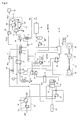
- Fig. 3 is a configuration diagram of conventional MCFC power generation system (MCFC-gas turbine hybrid system).
- a fuel gas FG such as urban gas
- a fuel humidifier 41 following desulfurization by a desulfurization agent 2 in a desulfurizer 1.
- the fuel gas is heated by the cathode exhaust of MCFC12, during which treatment water PW is sprayed on and evaporated; the preheated mixed gas of the fuel gas and vapor is then led to a pre-converter 9.
- the treatment water used here is supplied to a fuel humidifier 41 through a treatment tank 5 by a pump 6, after supply water W is treated in a water treatment device 4.
- the pre-converter 9 is a type of reformer, which contains a reforming catalyst 10, but does not include a heat source, and mainly modifies components heavier than ethane using its own sensible heat, and reforming of methane hardly occurs.
- the gas that outlets pre-converter 9 is heated to a temperature near working temperature of fuel cell by a fuel heater 11, and is supplied to MCFC12.
- MCFC12 is of an internal reforming type and an internal reformer 38 is built into the fuel cell.
- the catalytic combustor 14 As anode exhaust.
- the anode exhaust is mixed with air, which is the gas turbine exhaust, and the flammable component in the anode exhaust is combusted by combustion catalyst 15.
- the combustion gas with increased temperature is cooled by heat-exchanging with compressed air CA in a high temperature heat exchanger 16, and is then supplied to cathode C.
- cathode C CO 2 and oxygen are partly consumed in the power generation reaction (CO 2 + 1/2O 2 + 2e - -> CO 3 2 -) and discharged from cathode C.
- the cathode exhaust provides heat to the fuel side in fuel heater 11, flows into a low-temperature regeneration heat exchanger 32 to preheat compressed air, then provides heat to the fuel side in fuel humidifier 41, and is then emitted in the atmosphere.
- gas turbine generator 27 comprises a compressor 28, a turbine 29, and an electric generator 30 connected by a single axis; air AIR is compressed by the compressor 28 through filter 31, and the compressed air CA is preheated in the low-temperature regeneration heat exchanger 32, is subsequently heated to a predetermined temperature in the high temperature heat exchanger 16, and flows in to the turbine 29.
- turbine 29 work is done in the process of expanding to near atmospheric pressure, and the exhaust is supplied to the cathode through catalytic combustor 14 and high temperature heat exchanger 16.
- the shaft output obtained by subtracting power for compressor 28 and mechanical loss from the output of turbine 29 is transmitted to electric generator 30, thereby obtaining alternate current by use of exhaust heat of fuel cell.
- Fig. 4 is a configuration diagram of the apparatus used for separation and recovery of CO 2 from combustion fuel gas.
- Combustion fuel gas CG enters absorption tower 42 from the bottom part and contacts absorbent liquid LAB in the process until it is discharged from the top part, during which CO 2 in the combustion fuel gas is absorbed by absorbent liquid LAB.
- absorbent liquid RAB is pressurized by pump 43, preheated by heat exchanger 44, and is then fed from the upper part of regeneration tower 45.
- Absorbent liquid RAB is then heated by coming into contact with the hot gas arising from the lower part, while falling toward the lower part, thereby emitting the absorbed CO 2 .
- Re-boiler 46 is installed on the bottom part of regeneration tower 45, which heats the absorbent liquid with a heat medium HM. CO 2 and vapor flow from the bottom part toward the upper part of the regeneration tower, and, finally CO 2 gas CO 2 G is collected from the top. After emitting CO 2 , absorbent liquid LAB is pressurized by pump 47, cooled by heat exchanger 44 and cooler 48, and once again supplied from the upper part of the absorption tower.
- CO 2 separation recovery apparatus CO 2 contained in combustion fuel gas can be separated and collected, but energy consumption such as a heat source for the re-boiler and power for the pump is large, and the facility cost is also expensive.
- Fig. 1 is Fig. 3 disclosed in patent document 1.
- This diagram indicates that by utilizing the fact that combustion of the flammable component in the anode exhaust of solid oxide form fuel cell under oxygen, converts the combustion gas to CO 2 and H 2 O, cooling and separating H 2 O, CO 2 can be easily recovered. Therefore, that CO 2 is recoverable by cooling the anode exhaust of a fuel cell after combustion under oxygen and separating moisture, has already been disclosed by patent document 1.
- a fuel cell is, in short, the oxidation process of fuel gas, and anode exhaust is fuel gas in the state of partial oxidation. If the fuel gas supplied to a fuel cell is a hydrocarbon fuel or a fuel gas obtained from it, the anode exhaust is a partial oxidation product of the hydrocarbon fuel. By combusting under oxygen and cooling to remove water, CO 2 can be recovered.
- SOFC is used as a fuel cell. Since the electrolyte in SOFC has oxygen ion conductivity, oxygen alone migrates to the fuel pole (anode), even if air is supplied to the air pole (cathode), and reacts with hydrogen to generate electricity; thus, N 2 is never mixed into the anode exhaust. Therefore, since air and not just oxygen can be supplied to the cathode, oxygen is only necessary for combusting the anode exhaust under oxygen; thus the amount of oxygen consumption can be decreased.
- PAFC phosphoric acid form fuel cells
- PEFC polymer electrolyte fuel cells
- SOFC is used as a fuel cell
- preheating air 130 obtained by preheating air 120 using air preheater 110 is supplied to the cathode, and the heat source for the air preheater is the cathode exhaust.
- coal 340 and oxygen 350 is gasified in a coal gasification furnace 310 to obtain a gas, which is then desulfurized in a desulfurizer 320, passed through a methanol synthesis catalyst layer 330, meanwhile leading steam at its entrance and outlet; the gas exiting the catalyst layer is fed to anode A.
- the fuel gas fed causes an internal reforming reaction within the fuel cell, and power generation reaction occurs by the H 2 and CO produced.
- External oxygen is supplied to the resulting gas discharged from anode A, which is then led to burner 360; the combustion gas is further led to a heat exchanger 200, whereby water 220 is evaporated, which steam is used as a fuel reforming steam. Furthermore, the combustion gas cooled by heat exchanger 200 is subsequently led to a cooler 230, whereby water is separated, and the remaining gas is collected as CO 2 . Moreover, the collected water is used in order to generate steam.
- the fuel cell is limited to SOFC in the scope, and MCFC is not mentioned at all. The reason may be that the power generation principles differ and the same process is not applicable to MCFC.
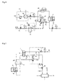
- Fig. 2 is equivalent to Fig. 14 disclosed in patent document 2, and is a hybrid system of MCFC, a gas turbine, and a steam turbine.
- the system uses oxygen as the oxidizer instead of air to enabled CO 2 recovery.
- the fuel cell of this system is MCFC, and methanol is supplied to the anode 407 from a tank, mixed with the recycled anode exhaust, and supplied to the anode. Moreover, a combustion gas obtained by combusting anode exhaust under oxygen and a gas turbine exhaust are mixed and supplied to the cathode 406.
- the cathode exhaust is led to a steam generator 408, and after generating steam, is led to a cooler 410, whereby moisture is separated.
- the steam generated by the steam generator is led to a steam turbine 409, and drives the steam turbine to generate electricity.
- the cathode exhaust from which moisture was separated by the cooler 410 i.e., mixed gas of CO 2 and O 2
- a compressor 411 of the gas turbine i.e., mixed gas of CO 2 and O 2
- Methanol and oxygen are supplied to the burner 403, and the combustion gas is supplied to the gas turbine, and work is generated during the process of expansion inside the gas turbine, thereby generating electricity.
- Exhaust from the gas turbine is supplied to the cathode.
- the anode exhaust is led to a burner 412, into which oxygen is supplied, and the combustible component in the anode exhaust is combusted. After this combustion gas gives heat to compressed gas in the heat exchanger 413, it is separated into two lines: in one line, moisture is separated by a cooler 414 and CO 2 gas is collected; the other line is supplied to the cathode.
- the quantity of CO 2 generated from methanol cannot exceed the amount of power generation reactions, oxygen cannot be fed in a quantity above that consumed in the power generation reaction, and the total amount of CO 2 and O 2 that is fed from the combustion gas of anode exhaust, and the total amount of CO 2 and O 2 that is fed from the methanol and O 2 burner must be in exact agreement with the quantity of those consumed by the power generation reaction.
- the temperature at the outlet of the gas turbine i.e. the cathode entrance
- the inlet temperature which is decided by the combustion of methanol
- CO 2 balance there is a factor, aside from CO 2 balance, that determines the flow rate of methanol.
- Nickel short-circuit is a fatal problem for a fuel cell, which occurs when nickel oxide constituting the cathode dissolves into the electrolyte as ions (NiO + CO 2 -> Ni 2+ + CO 3 2 -), which are then reduced by hydrogen and deposited in the electrolyte plate as metal nickel (Ni 2+ + H 2 + CO 3 2- -> Ni + H 2 O + CO 2 ), and increase in nickel deposition causes conduction between anode and cathode of the electrolyte plate, which should be insulated.
- gas composition at the cathode should be freely controllable; however, in the system disclosed in Fig. 2 , it is virtually impossible to change the CO 2 and O 2 concentrations at the cathode freely, while satisfying heat balance and CO 2 balance of the fuel cell.
- the present invention has been originated in order to solve the above-mentioned conventional problems. That is, the purpose of the present invention is to provide an MCFC power generation system, which minimizes the facility added to usual power generation facilities, drastically reduces or eliminates atmosphere discharge of CO 2 while simultaneously acquiring high power generation efficiency and heat recollection efficiency, and method of operating the same. Furthermore, the purpose of the present invention is to provide a MCFC power generation system, which enables adjustment of voltage and output of fuel cell within a certain range by adjusting cathode gas composition, enables drastic change in the ratio of heat and electricity, and enables the so-called thermoelectric variable operation, and method of operating the same.
- a MCFC power generation system comprising a fuel gas supply system for supplying fuel gas to a molten carbonate type fuel cell
- said fuel gas supply system comprises: a fuel heater that connects to an anode outlet; two lines that divide anode exhaust from said fuel heater, of which one line is connected to an anode exhaust circulation blower, mixing outlet gas from said blower with fuel gas externally supplied to said fuel cell, then mixing with steam for reforming, and leading to catalyst layer in a pre-converter, whereby pretreatment of mixed gas is performed, followed by heating with a fuel heater, and supplying to said fuel cell.
- amount of anode recycling is controlled so that the mixed temperature of the outlet gas from the anode exhaust circulation blower, the externally-supplied fuel gas, and the steam for reforming, is in the range of 250 to 400 °C, thereby obtaining high methane concentration in pre-converter outlet gas.
- a MCFC power generation system comprising a cathode gas circulation system for circulating cathode gas of a molten carbonate type fuel cell
- said cathode gas circulation system comprises: a closed circulation loop, comprising a cathode gas circulation blower whose intake side connects to a cathode outlet and discharge side connects to a cathode inlet, wherein the cathode outlet side is separated in to two lines, one of which is connected to a purge line comprising a flow rate regulation valve, and the other line is connected to a check valve, and further, downstream to said check valve, there is connected an oxygen supplying line and a CO 2 supplying line, each of which comprise a control valve.
- cathode inlet temperature can be controlled by simply supplying and mixing oxygen and CO 2 to the cathode outlet gas which passes through the check valve.
- a MCFC power generation system comprising an energy recovery system for recovering energy from anode exhaust of a molten carbonate type fuel cell
- said energy recovery system leads at least part of anode exhaust to a mixer, wherein said mixer comprises an oxygen supply line and a combustion gas recycle line; and mixed gas from the mixer outlet is led to a catalytic oxidizer, wherein combustible composition in said anode exhaust is combusted under oxygen; and combustion gas exiting said catalytic oxidizer first heats compressed air for a gas turbine that utilizes air as a working medium, then heats recycled CO 2 , and is led to an exhaust heat recovery boiler, thereby producing steam; and combustion gas exiting the evaporation side of the exhaust heat recovery boiler is separated into two lines, of which one is connected to a combustion gas recycling blower to recycle cooled combustion gas to the mixer, and the other line feeds to a water supply heater of the exhaust heat recycling boiler.
- said system comprises a gas turbine that utilizes air as its operation medium, which receives heat from high temperature combustion gas from said catalytic oxidizer through an air heater, and air, which is the above-mentioned operation medium is independent and does not mix with any other fluids.
- said system is constructed so that compressed air is first heated by a regenerated heat exchanger, and steam is produced by an exhaust heat recovery boiler, subsequently; and at the exhaust heat recovery boiler, temperature of regenerated heat exchanger outlet is controlled so as to enable constant production of steam necessary for reforming.
- rotation frequency of the combustion gas recycling blower is controlled so as to maintain a constant preset temperature at the outlet of the catalyst oxidization chamber.
- said system comprises a damper that enables switching of position of recycling combustion gas from a low temperature part to a high temperature part.
- a method for operating the above-described MCFC power generation system wherein the amount of combustion gas passing through an air heater is increased by switching position of recycling combustion gas from a low temperature part to a high temperature part, thereby increasing gas turbine output by increasing amount of heat provided to compressed air, while, conversely decreasing amount of steam production at the exhaust heat recovery boiler.
- a method for operating the above-described MCFC power generation system wherein circulation flow rate of the combustion gas recycling blower is gradually increased by gradually reducing the set value for the outlet temperature of the catalytic oxidizer, thereby decreasing the outlet temperature of the catalytic oxidizer, and decreasing the amount of heat provided to the compressed air through the air heater, thereby decreasing output of gas turbine, and conversely increasing the amount of steam production at the exhaust heat recovery boiler.
- the amount of steam production by the exhaust heat recovery boiler is at a maximum when the supply of steam for reforming is switched from the exhaust heat recovery boiler at the gas turbine side to that at the combustion gas side while gas turbine output is near zero, and then the gas turbine is turned off.
- a method for operating the above-described MCFC power generation system wherein voltage of the fuel cell is maintained at a near constant throughout its life, by increasing the concentration of CO 2 and O 2 in the cathode circulation system in an amount that corresponds to voltage degradation, in correspondence with time-dependent voltage degradation of fuel cell.
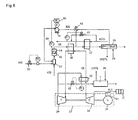
- Fig. 5 is a configuration diagram of the entire MCFC power generation system of the present invention.
- fuel gas FG such as urban gas, externally-supplied, is desulfurized by a desulfurization agent 2 in a desulfurization facility 1 and supplied to a pre-converter 9 via a filter 3, part of the anode exhaust is mixed in at a high temperature along the way.
- steam for reforming is mixed in an amount matching that of the externally-supplied fuel gas such as urban gas, and components heavier that ethane in the externally-supplied fuel gas such as urban gas is reformed in the course of passing through a reforming catalyst layer 10 in the pre-converter, while at the same time, H 2 , CO, and CO 2 in the recycled anode exhaust conversely initiate methanation reaction.
- the order by which externally-supplied fuel gas such as urban gas, part of the anode exhaust, and steam for reforming are mixed, may be as indicated in Fig. 5 , or preferably, for preventing drain generation, urban gas may be added after mixing part of the anode exhaust with steam for reforming; although the site at which mixing occurs is indicated as a piping in Fig. 5 , methods such as mixing with a mixer built between the piping and mixing inside the pre-converter may also be applied, and Fig. 5 merely shows one example among such methods.
- Gas exiting the pre-converter is led to a fuel heater 11, is heated by anode exhaust to a temperature slightly lower than the working temperature of the fuel cell, and is supplied to the fuel cell 12.
- the fuel cell is an internal reforming type MCFC, wherein reformer 38 is built inside the fuel cell, and fuel gas is reformed inside the fuel cell to generate H 2 and CO, which become fuel for MCFC.
- the catalytic combustor 14 comprises a combustion catalyst layer 15, which combusts the combustible component in the anode exhaust.
- the combustion gas exiting the catalytic combustor 14 is led to a high temperature heat exchanger 16, and heats the compressed air CA to a turbine inlet temperature. Subsequently, heat is provided to RCO 2 , which is recycled CO 2 , with a CO 2 heater 17, and the gas is led to an exhaust heat recovery boiler 18.
- the exhaust heat recovery boiler 18 comprises an evaporation part EVA and a feed-water heating part ECO, and although the heat source is the same combustion gas, since the recycled combustion gas RCG branches from the outlet of the evaporation part of the exhaust heat recovery boiler 18, the flows rate of the combustion gas differ between the evaporation part and a feed-water heating part.
- the position at which combustion gas is recycled is indicated as the outlet of the evaporation part of the exhaust heat recovery boiler in Fig. 5 , it may also be positioned at the outlet of the CO 2 heater 17 or the outlet of the high temperature heat exchanger 16; although power generation efficiency becomes higher as the position of recycling becomes higher in temperature, exhaust heat recovery efficiency decreases, and has both features.
- the recycled combustion gas is pressurized by a combustion gas recycling blower 19, and sent to a mixer 13.
- a combustion gas recycling blower 19 The recycled combustion gas is pressurized by a combustion gas recycling blower 19, and sent to a mixer 13.
- Fig. 5 indicated that mixing occurs in the oxygen line, the mixing of anode exhaust, oxygen and recycled combustion gas, may be performed by a method that uses mixer 13, and other such methods, and Fig. 5 is not intended to specify a method.
- the combustion gas exiting the feed-water heating part of the exhaust heat recovery boiler 18 is cooled by a cooler 20, and condensed water is separated by a KO drum 21.
- the gas exiting the KO drum 21 is substantially CO 2 gas, if necessary, it may further be led to a dehumidification system 22, which decreases temperature to remove moisture.
- the dehumidification system 22 comprises a freezer 23, a heat exchanger 24, and a KO drum 25.
- CO 2 concentration is raised to about 95%. Part of it is pressurized by a CO 2 recycling blower 26, and after being preheated with a CO 2 warmer 17, is supplied to the cathode gas circulation system.
- the remaining CO 2 gas is recovered by the high concentration CO 2 recovery apparatus 70 in high concentration, and discharge to the atmosphere is mostly lost.
- the cathode gas circulation system forms a closed cycle in which circulation is induced by a cathode gas circulating blower 36, and oxygen consumed by the power generation reaction (CO 2 + 1/2O 2 +2e - -> CO 3 2 - ) of the cathode is supplied by an oxygen supply plant 33.
- oxygen supply plant 33 is indicated in Fig 5 as being composed of an air compressor 34 and a separator 35, various systems, such as PSA (Pressure Swing Adsorber) and liquefaction separation are known for oxygen supply plant, and the present invention does not limit the specifics of the oxygen supply plant.
- recycled CO 2 obtained by combustion of anode exhaust under oxygen, is supplied to the cathode gas circulation system after being cooled and dehumidified.
- the temperature of cathode gas is higher at the outlet than at the inlet, due to heat generation accompanying the power generation reaction in the fuel cell, but may be adjusted to a temperature close to that of the inlet temperature by mixing oxygen near normal temperature with recycled CO 2 preheated to 250-450 °C.
- Such temperature control is performed by controlling the outlet temperature of CO 2 heater 17.
- the basic structure of the MCFC power generation facility part of the present invention additionally comprises a gas turbine generator, which utilizes air as its operation medium.
- Air is led to a compressor 28 in a gas turbine generator 27 via a filter 31, and the compressed air CA is first heated by the exhaust from a turbine 29 in a regeneration heat exchanger 32, followed by heat exchanging with combustion gas CG of anode exhaust in the high temperature heat exchanger 16, whereby the compressed air heated to turbine inlet temperature is led to the turbine 29.
- the turbine exhaust is led to the regeneration heat exchanger 32, where it provides heat to compressed air, and subsequently to an exhaust heat recovery boiler 7.
- the exhaust heat recovery boiler 7 Low-pressure steam required for reforming is generated, and the turbine exhaust exiting the exhaust heat recovery boiler is emitted to the atmosphere.
- the reforming reaction and methanation reaction can proceed simultaneously by mixing part of the anode gas with externally-supplied fuel gas, such as urban gas, adding steam for reforming, and passing through one reforming catalytic layer; since an endothermic and exothermic reaction proceed simultaneously, temperature change is mutually mitigated, and maintaining the reaction temperature to that intended becomes easy. Operations, such as preheating of gas and cooling of a reaction machine, are unnecessary in this process.
- externally-supplied fuel gas such as urban gas
- drain will occur if saturated steam is mixed; therefore, to prevent generation of drain at mixing, steam should be mixed after mixing part of the hot anode exhaust with fuel gas, or fuel gas should be mixed after mixing part of the hot anode exhaust with steam.
- Fig. 6 describes the cathode gas circulation system part of Fig. 5 in further detail. It is necessary to supply CO 2 and O 2 which are consumed by the power generation reaction (CO 2 + 1/2O 2 +2e - -> CO 3 2- ) at the cathode, and purged.
- the reaction amount may be calculated from the direct-current of the fuel cell, and the purged amount may be checked by flow control valve 53.
- O 2 from the oxygen plant established in the exterior of the MCFC power generation plant is controlled by the flow control valve 51, and is supplied at a temperature near normal temperature.
- CO 2 is supplied to the cathode gas circulation system by controlling the flow rate of recycled CO 2 (RCO 2 ), obtained by combustion of anode exhaust under oxygen, cooling, and water-extraction, with a flow control valve 52, and by controlling the temperature with a temperature control valve 40 built in a CO 2 heater 36. Since the temperature of the gas passing through the cathode is higher at the outlet than the inlet due to heat generated by the power generation reaction, the temperature is controlled to recover the inlet temperature by supplying and mixing CO 2 and O 2 .
- the temperature of recycled CO 2 is adjusted by a CO 2 heater so that the temperature of the mixed gas after adiabatic compression by the cathode gas circulation blower matches the cathode inlet temperature.
- the circulation volume of the cathode gas circulation blower is controlled so that the cathode outlet gas temperature is kept constant.
- the cathode outlet of the cathode circulation system is divided into two lines, of which one is connected to a purge line that is equipped with a flow control valve 53, and the other is equipped with a check valve 54 and connects the supply line of CO 2 and O 2 downstream of the check valve 54.
- the cathode gas circulation system of the present invention enables free change of the gas composition, as well as free fluctuation of the amount of circulation depending on the degree of heat generation in the fuel cell. Moreover, such changes do not affect other subsystems.
- Plant performance when the cathode gas composition in the present invention is changed is shown in Table 1, as one example.
- the CO 2 and O 2 concentrations in Table 1 are not meant to indicate the maximum concentration, but are rather concentrations with the influence of nickel short circuit taken in consideration; power generation efficiency is still improved by 5%. Further, operation at high concentration may be performed when high power generation efficiency is called for, and can easily be returned to standard operating condition.
- life of a fuel cell is defined as the point at which cell voltage deteriorates 10%. If operation time per year is assumed to be 8000 hours and the cell life is five years, that is 40000 hours, deterioration occurs 1% each per half a year, and the output of fuel cell and power generation efficiency will fall 1% per half a year, as well, in proportion to the voltage.
- CO 2 and O 2 concentration at the cathode can be gradually raised, in correspondence to the deterioration of the fuel cell, thereby keeping the voltage of the fuel cell constant.
- Fig. 10 shows the data for voltage fixed operation.
- This figure is an example of CO 2 and O 2 concentration change for maintaining the same performance as that of standard operating conditions for five years; by applying such operation, the output and power generation efficiency of the fuel cell can be increased relatively by an average of 5% during cell life.
- the time during which CO 2 partial pressure is extremely high is kept short, and therefore the total accumulation of metal nickel, which leads to nickel short circuit, can be suppressed; thus, this is one operating method that can enhance power generation efficiency while suppressing nickel short circuit.
- Fig. 7 is a detailed drawing that describes the fuel gas supply system in Fig. 5 ; the anode outlet is connected to a fuel heater 11 the temperature of the outlet gas from pre-convertor 9 is heated, utilizing the anode exhaust as a heat source, to a temperature close to the operation temperature of fuel gas.
- the anode exhaust whose temperature then decreases, is divided into two lines, one of which is connected to an anode exhaust circulation blower, and the blower outlet gas is mixed with externally-supplied fuel gas, such as urban gas.
- Fuel gas, such as urban gas is supplied by adjusting its flow rate with a flow control valve 56. Subsequently, it is mixed with steam for reforming such urban gas, and the like. Steam is supplied by adjusting its flow rate with a flow control valve 57.
- Fig. 7 indicates that mixing occurs in the piping, mixing may be performed by methods such as one that uses a mixer, or one where mixing is performed inside a pre-convertor 9, and the present invention does not specify a mixing method.
- This mixed gas is then led to a reforming catalyst layer 10 in a pre-converter 9.
- reforming of components heavier than ethane in the urban gas occurs, and CO, CO 2 , and H 2 O in the anode recycle gas undergo methanation reaction. Reforming reaction is an endothermic reaction, while methanation reaction is an exothermic reaction; so, by these two reactions proceeding simultaneously, temperature changes are mutually suppressed, thereby making it easy to maintain the working temperature of the pre-converter to that desired.
- MCFC of Fig. 7 is an internal reforming type and the reforming reaction (CH 4 +H 2 O -> CO+3H 2 ), which is an endothermic reaction is used for cooling of the fuel cell, it is desirable that the methane concentration is high; by controlling the outlet temperature of the catalyst layer in the pre-converter to 250-450 °C using temperature controller 58, and by controlling the flow rate of urban gas and the like and the flow rate of steam for reforming using rate controller 39 equipped in the anode exhaust circulation blower, the amount of recycling is controlled.
- the constituent features of the fuel supplying system of the present invention is: to connect the anode outlet to a fuel heater to decrease the temperature of the anode exhaust; to divide the cooled anode exhaust line in to two systems, of which one is connected to an anode exhaust circulation blower; to mix outlet gas from anode exhaust circulation blower with fuel gas, such as urban gas, and steam for reforming, thereby raising the temperature to that of the gas supplied to the pre-converter without using a heat exchanger; subsequently leading mixed gas to reforming catalyst layer in the pre-converter, which does not have a heat source; to retain an operating temperature in the range of 250-450 °C, so that the methane concentration of the pre-converter outlet gas is increased; and to retain a anode exhaust recycling rate in the range of about 20 to 40% for the same reason.
- the performances of the present invention are compared for cases where anode exhaust is recycled and not recycled, and shown in Table 2. Although the power generation efficiency does not change, the heat recovery rate improves drastically. Moreover, although changing the anode exhaust recycling rate does not change the power generation efficiency of the overall plant, individual factors vary. When the anode recycling rate is raised, the amount of urban gas supplied decreases, as does the amount of steam for reforming supplied, the voltage of the fuel cell drops, and therefore, the output of the fuel cell also drops; the output of the gas turbine decreases, as does the power within the facility.
- Fig. 8 describes the energy recovery system of Fig. 5 that effectively utilizes combustion heat obtained by the combustion of anode exhaust under oxygen via various heat exchangers.
- the anode exhaust AEG is mixed with the oxygen OXG and the recycling combustion gas RCG in a mixer 13. Since the amount of combustible components in anode exhaust is calculable from the amount of fuel supplied, fuel consumed, and the direct-current of the fuel cell, etc., the amount of oxygen required is calculated based on that value, and supplied by controlling with a flow control valve 59. On the other hand, the once cooled combustion gas RCG is recycled to the mixer by a combustion gas recycling blower. Since the rise in temperature becomes excessive if the anode exhaust is simply combusted under oxygen, combustion gas of low-temperature is recycled so that the outlet temperature of the catalytic combustor can be adjusted.
- the combustible gas in the anode exhaust is combusted by the combustion catalyst in the catalytic combustor 14, and the temperature rises.
- the rate controller 61 in the combustion gas recycling blower controls the flow rate to suit the preset outlet temperature of the catalytic combustor. This preset temperature may be changed as needed.
- the combustion gas leaving the catalytic combustor 14 first provides heat to compressed air through a high temperature heat exchanger 16, then provides heat to recycled CO 2 through the CO 2 warmer, and subsequently generates steam in the exhaust heat recovery boiler 18.
- combustion gas is recycled when exiting the evaporation part EVA of the exhaust heat recovery boiler.
- the remaining combustion gas is sent to the water supply heater ECO of the exhaust heat recovery boiler.
- the combustion gas is recycled at the outlet of the high temperature heat exchanger 16. This change is performed by gradually switching the gate opening of the damper 62 from the low temperature side to the high temperature side.
- the flow rate of combustion gas recycling blower increases so that the preset value for the outlet temperature of the catalytic combustor is maintained. Therefore, the quantity of the combustion gas, which passes through the high temperature heat exchanger 16 increases, increasing the amount of heat provided to compressed air.
- the amount of air in the gas turbine is increased by speed controller 64 of the gas turbine generator. As a result, even though the gas turbine output increases, the amount of steam generation is reduced, since the amount of heat going to the exhaust heat recovery boiler decreases.
- the standard operating condition and the high-output operating mode are compared in Table 3.
- power generation efficiency improves by 2 points, but conversely, the heat recovery rate falls by 6 points.
- Whichever operating mode is desirable is decided by the balance between thermal demand and power demand.
- the electric generator is to be a motor/generator, which is additionally rotation frequency-variable, and the amount of air flow is to be changeable according to the operational status of the fuel cell.
- Heat and electricity variable operation is made possible by using the energy recovery system of Fig. 8 .
- the conditions that maximize the electric output are, as described previously, the operation modes in which the position of combustion gas recycling is switched to the high temperature heat exchanger outlet.
- the operating method which maximizes heat recovery is as described below.
- the position for recycling combustion gas is set to the exit of the evaporation part of the exhaust heat recovery boiler, and the preset value of the outlet temperature of the catalyst oxidizer is gradually lowered. This causes the flow rate of combustion gas recycling blower to increase.
- the outlet temperature of the catalyst oxidizer decreases, the amount of heat provided to compressed air through high temperature heat exchanger 16 decreases, thereby causing the gas turbine entrance temperature to drop.
- the gas turbine output decreases.
- the amount of heat that heats recycled CO 2 at the CO 2 heater, in the process does not change, the amount of evaporation at the exhaust heat recovery boiler increases at an amount corresponding to the decrease in the amount of heat provided to the gas turbine.
- Fig. 9 The relationship among the amount of combustion gas recycled, the inlet temperature of the gas turbine and the output, are shown in Fig. 9 . If the outlet temperature of the catalytic combustor decreases below a certain temperature, the output of the gas turbine becomes zero. At this point, supply of steam for reforming is switched from the exhaust heat recovery boiler on the gas turbine side to the exhaust heat recovery boiler on the combustion gas side, and the gas turbine is turned off. Since all the heat that was contained in the gas turbine during standard operation goes into the exhaust heat recovery boiler on the combustion gas size when the gas turbine is stopped, the amount of heat recovery is at its maximum. Comparison between standard operation and maximum heat recovery is shown in Table 4.
Landscapes
- Life Sciences & Earth Sciences (AREA)
- Engineering & Computer Science (AREA)
- Sustainable Development (AREA)
- Chemical & Material Sciences (AREA)
- Manufacturing & Machinery (AREA)
- Sustainable Energy (AREA)
- Chemical Kinetics & Catalysis (AREA)
- Electrochemistry (AREA)
- General Chemical & Material Sciences (AREA)
- Combustion & Propulsion (AREA)
- Fuel Cell (AREA)
Applications Claiming Priority (2)
| Application Number | Priority Date | Filing Date | Title |
|---|---|---|---|
| JP2008294106 | 2008-11-18 | ||
| PCT/JP2009/069429 WO2010058749A1 (fr) | 2008-11-18 | 2009-11-16 | Système de génération d'énergie mcfc et son procédé de fonctionnement |
Publications (2)
| Publication Number | Publication Date |
|---|---|
| EP2360764A1 true EP2360764A1 (fr) | 2011-08-24 |
| EP2360764A4 EP2360764A4 (fr) | 2014-03-12 |
Family
ID=42198189
Family Applications (1)
| Application Number | Title | Priority Date | Filing Date |
|---|---|---|---|
| EP09827530.8A Withdrawn EP2360764A4 (fr) | 2008-11-18 | 2009-11-16 | Système de génération d'énergie mcfc et son procédé de fonctionnement |
Country Status (5)
| Country | Link |
|---|---|
| US (1) | US20110223500A1 (fr) |
| EP (1) | EP2360764A4 (fr) |
| JP (3) | JP5331819B2 (fr) |
| KR (1) | KR101352219B1 (fr) |
| WO (1) | WO2010058749A1 (fr) |
Cited By (5)
| Publication number | Priority date | Publication date | Assignee | Title |
|---|---|---|---|---|
| CN103410614A (zh) * | 2013-08-21 | 2013-11-27 | 华北电力大学 | 用两级常压mcfc回收燃气轮机排气中co2的复合动力系统 |
| DK178834B1 (en) * | 2016-03-15 | 2017-03-06 | Mogens Skou Nielsen | A system and method to generate power using dry ice |
| CN106960969A (zh) * | 2015-12-21 | 2017-07-18 | 本田技研工业株式会社 | 燃料电池系统 |
| CN108301922A (zh) * | 2017-01-12 | 2018-07-20 | 华北电力大学(保定) | 基于燃气轮机和熔融碳酸盐燃料电池的混合供能系统 |
| CN114094242A (zh) * | 2021-12-29 | 2022-02-25 | 重庆大学 | 处理脱硫废水同时还原二氧化碳的流动式光电化学电池 |
Families Citing this family (43)
| Publication number | Priority date | Publication date | Assignee | Title |
|---|---|---|---|---|
| GB2491562A (en) * | 2011-05-23 | 2012-12-12 | Alstom Technology Ltd | Fossil fuel power plant with gas turbine and MCFC arrangements |
| KR101352198B1 (ko) * | 2011-12-27 | 2014-01-16 | 포스코에너지 주식회사 | 연료전지 하이브리드 시스템 |
| WO2013100714A1 (fr) * | 2011-12-30 | 2013-07-04 | 두산중공업 주식회사 | Système de récupération de dioxyde de carbone utilisant une pile à combustible |
| KR101401451B1 (ko) * | 2012-02-14 | 2014-05-29 | 두산중공업 주식회사 | 열교환형 촉매 산화기 및 이를 이용한 고농도 이산화탄소 회수장치 |
| KR101408139B1 (ko) * | 2011-12-30 | 2014-06-17 | 두산중공업 주식회사 | 연료전지를 이용한 이산화탄소 회수 시스템 |
| KR101451839B1 (ko) * | 2012-12-18 | 2014-10-16 | 두산중공업 주식회사 | 연료 전지 시스템 및 그 제어 방법 |
| KR101397091B1 (ko) * | 2012-12-28 | 2014-05-19 | 포스코에너지 주식회사 | 연료 전지 시스템 |
| US9077008B2 (en) | 2013-03-15 | 2015-07-07 | Exxonmobil Research And Engineering Company | Integrated power generation and chemical production using fuel cells |
| EP2973819B1 (fr) | 2013-03-15 | 2018-10-31 | ExxonMobil Research and Engineering Company | Intégration de piles à combustible à carbonate fondu dans la synthèse de fischer-tropsch |
| US9755258B2 (en) | 2013-09-30 | 2017-09-05 | Exxonmobil Research And Engineering Company | Integrated power generation and chemical production using solid oxide fuel cells |
| US9556753B2 (en) | 2013-09-30 | 2017-01-31 | Exxonmobil Research And Engineering Company | Power generation and CO2 capture with turbines in series |
| US9819042B2 (en) | 2013-09-30 | 2017-11-14 | Exxonmobil Research And Engineering Company | Fuel cell integration within a heat recovery steam generator |
| CN104196582B (zh) * | 2014-07-03 | 2015-10-21 | 华北电力大学 | 基于mcfc电化学法捕集igcc系统中co2的复合动力系统 |
| KR101511100B1 (ko) | 2015-01-27 | 2015-04-10 | (주)지케이홀딩스 | 연료전지시스템에서 발생한 고온배출가스를 이용한 발전시스템 및 발전방법 |
| US10686204B2 (en) | 2015-08-10 | 2020-06-16 | Nissan Motor Co., Ltd. | Solid oxide fuel cell system |
| US10770741B2 (en) * | 2016-08-31 | 2020-09-08 | Toshiba Energy Systems & Solutions Corporation | Fuel cell module with hydrodesulfurizer and preheating |
| US10854899B2 (en) * | 2016-11-04 | 2020-12-01 | Cummins Enterprise Llc | Power generation system using cascaded fuel cells and associated methods thereof |
| JP7108848B2 (ja) * | 2016-11-28 | 2022-07-29 | パナソニックIpマネジメント株式会社 | 燃料電池システム |
| CN108301923A (zh) * | 2017-01-13 | 2018-07-20 | 华北电力大学(保定) | 一种富氧燃烧与熔融碳酸盐燃料电池混合发电系统 |
| CN107221695B (zh) * | 2017-06-30 | 2023-05-30 | 北京理工大学 | 一种以生物质气化制氢的燃料电池系统及其发电方法 |
| US10622656B2 (en) | 2017-10-11 | 2020-04-14 | Saudi Arabian Oil Company | Method and system for capturing high-purity CO2 in a hydrocarbon facility |
| CN108321416B (zh) * | 2018-03-29 | 2023-09-29 | 中国华能集团清洁能源技术研究院有限公司 | Co2近零排放的整体煤气化燃料电池发电系统及方法 |
| CN109148919B (zh) * | 2018-10-11 | 2023-06-09 | 中国华能集团清洁能源技术研究院有限公司 | 一种利用煤气高温显热的整体煤气化燃料电池发电系统及方法 |
| CN109346744B (zh) * | 2018-11-15 | 2023-04-25 | 中国华能集团清洁能源技术研究院有限公司 | 一种采用超临界co2底循环的天然气燃料电池发电系统及方法 |
| WO2020112895A1 (fr) | 2018-11-30 | 2020-06-04 | Exxonmobil Research And Engineering Company | Motif de catalyseur de reformage pour pile à combustible fonctionnant avec une utilisation améliorée du co2 |
| US11695122B2 (en) | 2018-11-30 | 2023-07-04 | ExxonMobil Technology and Engineering Company | Layered cathode for molten carbonate fuel cell |
| WO2020112812A1 (fr) | 2018-11-30 | 2020-06-04 | Exxonmobil Research And Engineering Company | Fonctionnement de piles à combustible à carbonate fondu présentant une utilisation du co2 améliorée |
| KR102662253B1 (ko) | 2018-11-30 | 2024-04-29 | 퓨얼셀 에너지, 인크 | Co2 이용률이 향상된 용융 탄산염 연료 전지의 증가된 압력 작동 |
| US11211621B2 (en) | 2018-11-30 | 2021-12-28 | Exxonmobil Research And Engineering Company | Regeneration of molten carbonate fuel cells for deep CO2 capture |
| CN113228361B (zh) * | 2018-11-30 | 2023-09-22 | 燃料电池能有限公司 | 具有提高的co2利用率的熔融碳酸盐燃料电池的高压操作 |
| US11476486B2 (en) | 2018-11-30 | 2022-10-18 | ExxonMobil Technology and Engineering Company | Fuel cell staging for molten carbonate fuel cells |
| JP2023503995A (ja) | 2019-11-26 | 2023-02-01 | エクソンモービル・テクノロジー・アンド・エンジニアリング・カンパニー | 燃料電池モジュールのアセンブリおよびそれを使用するシステム |
| JP2023503473A (ja) | 2019-11-26 | 2023-01-30 | エクソンモービル・テクノロジー・アンド・エンジニアリング・カンパニー | 高電解質充填レベルでの溶融炭酸塩型燃料電池の作動 |
| US20210300788A1 (en) * | 2020-03-29 | 2021-09-30 | Chaac Holdings, Inc. | Atmospheric water and power generation compression apparatus, system and method |
| CN111874863B (zh) * | 2020-08-07 | 2023-05-30 | 华北电力大学(保定) | 一种太阳能光催化制氢燃料电池发电系统 |
| US11978931B2 (en) | 2021-02-11 | 2024-05-07 | ExxonMobil Technology and Engineering Company | Flow baffle for molten carbonate fuel cell |
| CN113540504B (zh) * | 2021-07-16 | 2023-06-23 | 中国科学院上海应用物理研究所 | 热泵式-氢能复合储能发电方法及装置 |
| CN113530677A (zh) * | 2021-07-30 | 2021-10-22 | 中国华能集团清洁能源技术研究院有限公司 | 一种前置燃料电池的天然气联合循环发电系统及方法 |
| CN113464279A (zh) * | 2021-07-30 | 2021-10-01 | 中国华能集团清洁能源技术研究院有限公司 | 一种采用燃料电池调制合成气成分的igcc系统及工作方法 |
| CN114371745B (zh) * | 2021-12-29 | 2022-09-27 | 徐州捷科思网络科技有限公司 | 一种温度控制系统 |
| CN114635815B (zh) * | 2022-04-01 | 2023-04-28 | 招商局重工(深圳)有限公司 | 一种甲醇燃料供给系统及其控制方法 |
| CN115466637B (zh) * | 2022-09-15 | 2024-03-22 | 西安交通大学 | 一种耦合生物质能及太阳能的燃料电池发电系统及方法 |
| CN117599607A (zh) * | 2023-11-14 | 2024-02-27 | 常熟荣瑞灭菌技术有限公司 | 一种新型高效节能eog处理系统 |
Family Cites Families (14)
| Publication number | Priority date | Publication date | Assignee | Title |
|---|---|---|---|---|
| JPS62276764A (ja) * | 1986-05-26 | 1987-12-01 | Hitachi Ltd | 燃料電池の運転法 |
| JPS63141268A (ja) * | 1986-12-03 | 1988-06-13 | Ishikawajima Harima Heavy Ind Co Ltd | 天然ガス改質溶融炭酸塩型燃料電池発電装置 |
| JPS63174282A (ja) * | 1987-01-12 | 1988-07-18 | Hitachi Ltd | 燃料電池発電方法 |
| JP2846105B2 (ja) | 1990-03-14 | 1999-01-13 | 三菱重工業株式会社 | 燃焼装置 |
| JPH05101839A (ja) * | 1991-05-13 | 1993-04-23 | Mitsubishi Electric Corp | 溶融炭酸塩型燃料電池発電装置 |
| JP3139574B2 (ja) * | 1992-06-19 | 2001-03-05 | 石川島播磨重工業株式会社 | 燃料電池発電装置 |
| JPH0896824A (ja) * | 1994-09-29 | 1996-04-12 | Ishikawajima Harima Heavy Ind Co Ltd | 溶融炭酸塩型燃料電池発電装置 |
| JPH10302820A (ja) * | 1997-04-24 | 1998-11-13 | Ishikawajima Harima Heavy Ind Co Ltd | 燃料電池発電設備 |
| JPH1126004A (ja) | 1997-07-02 | 1999-01-29 | Toshiba Corp | 発電システム |
| JP3072630B2 (ja) * | 1997-12-15 | 2000-07-31 | 溶融炭酸塩型燃料電池発電システム技術研究組合 | 燃料電池複合発電装置 |
| JP2000228208A (ja) * | 1999-02-05 | 2000-08-15 | Ishikawajima Harima Heavy Ind Co Ltd | 燃料電池とガスタービンの複合装置 |
| JP2000331698A (ja) | 1999-05-19 | 2000-11-30 | Ishikawajima Harima Heavy Ind Co Ltd | ガスタービン排ガスを用いた燃料電池発電装置 |
| US7285350B2 (en) * | 2002-09-27 | 2007-10-23 | Questair Technologies Inc. | Enhanced solid oxide fuel cell systems |
| WO2005101562A1 (fr) * | 2004-03-31 | 2005-10-27 | Modine Manufacturing Company | Humidificateur de combustible et prechauffeur destine a etre utilise dans un systeme de pile a combustible |
-
2009
- 2009-11-16 EP EP09827530.8A patent/EP2360764A4/fr not_active Withdrawn
- 2009-11-16 WO PCT/JP2009/069429 patent/WO2010058749A1/fr active Application Filing
- 2009-11-16 US US13/129,801 patent/US20110223500A1/en not_active Abandoned
- 2009-11-16 JP JP2010539222A patent/JP5331819B2/ja not_active Expired - Fee Related
- 2009-11-16 KR KR1020117011593A patent/KR101352219B1/ko not_active IP Right Cessation
-
2013
- 2013-04-30 JP JP2013095483A patent/JP2013191572A/ja active Pending
- 2013-04-30 JP JP2013095493A patent/JP2013219034A/ja active Pending
Non-Patent Citations (2)
| Title |
|---|
| No further relevant documents disclosed * |
| See also references of WO2010058749A1 * |
Cited By (8)
| Publication number | Priority date | Publication date | Assignee | Title |
|---|---|---|---|---|
| CN103410614A (zh) * | 2013-08-21 | 2013-11-27 | 华北电力大学 | 用两级常压mcfc回收燃气轮机排气中co2的复合动力系统 |
| CN103410614B (zh) * | 2013-08-21 | 2015-12-23 | 华北电力大学 | 用两级常压mcfc回收燃气轮机排气中co2的复合动力系统 |
| CN106960969A (zh) * | 2015-12-21 | 2017-07-18 | 本田技研工业株式会社 | 燃料电池系统 |
| CN106960969B (zh) * | 2015-12-21 | 2019-09-06 | 本田技研工业株式会社 | 燃料电池系统 |
| DK178834B1 (en) * | 2016-03-15 | 2017-03-06 | Mogens Skou Nielsen | A system and method to generate power using dry ice |
| CN108301922A (zh) * | 2017-01-12 | 2018-07-20 | 华北电力大学(保定) | 基于燃气轮机和熔融碳酸盐燃料电池的混合供能系统 |
| CN114094242A (zh) * | 2021-12-29 | 2022-02-25 | 重庆大学 | 处理脱硫废水同时还原二氧化碳的流动式光电化学电池 |
| CN114094242B (zh) * | 2021-12-29 | 2023-09-15 | 重庆大学 | 处理脱硫废水同时还原二氧化碳的流动式光电化学电池 |
Also Published As
| Publication number | Publication date |
|---|---|
| KR101352219B1 (ko) | 2014-01-15 |
| JP2013219034A (ja) | 2013-10-24 |
| KR20110086110A (ko) | 2011-07-27 |
| US20110223500A1 (en) | 2011-09-15 |
| JPWO2010058749A1 (ja) | 2012-04-19 |
| JP2013191572A (ja) | 2013-09-26 |
| WO2010058749A1 (fr) | 2010-05-27 |
| JP5331819B2 (ja) | 2013-10-30 |
| EP2360764A4 (fr) | 2014-03-12 |
Similar Documents
| Publication | Publication Date | Title |
|---|---|---|
| EP2360764A1 (fr) | Système de génération d'énergie mcfc et son procédé de fonctionnement | |
| US9373856B2 (en) | Method of recycling and tapping off hydrogen for power generation apparatus | |
| EP2360765A1 (fr) | Système de production électrique de mcfc à recyclage d'hydrogène | |
| JP6397502B2 (ja) | 水素製造のための改質装置・電解装置・精製装置(rep)組立体、同組立体を組み込むシステムおよび水素製造方法 | |
| JP3316393B2 (ja) | 燃料電池発電システム及びその運転方法 | |
| JP7155241B2 (ja) | 燃料電池システム及び燃料電池システムの運転方法 | |
| JP4450623B2 (ja) | 燃料電池システム | |
| JP2009048854A (ja) | 燃料電池発電装置およびその制御方法 | |
| JP4342172B2 (ja) | エネルギー併給システム | |
| JP6698763B2 (ja) | 液化二酸化炭素回収型燃料電池発電システム | |
| JPH07230819A (ja) | 自己熱交換型断熱プレリフォーマを有する内部改質型固体電解質燃料電池システム | |
| JP3956208B2 (ja) | 燃料電池発電システムとその運転方法 | |
| JP7148320B2 (ja) | 二酸化炭素回収型燃料電池発電システム | |
| JP2009176659A (ja) | 燃料電池発電システムおよびその制御方法 | |
| JP4578787B2 (ja) | ハイブリッド型燃料電池システム | |
| JP5134309B2 (ja) | 燃料電池発電装置およびその制御方法 | |
| JP4938299B2 (ja) | 燃料電池発電装置の運転方法 | |
| JP6847900B2 (ja) | 二酸化炭素回収型燃料電池発電システム | |
| JP3886887B2 (ja) | 燃料電池発電システム | |
| JPH08339815A (ja) | 燃料電池発電装置 | |
| KR101207799B1 (ko) | 기력발전소의 연료전지 시스템 | |
| JPH0757754A (ja) | 溶融炭酸塩型燃料電池発電装置のアノード入口温度制御方法 | |
| JP2009230927A (ja) | 燃料電池システム | |
| JP2011129490A (ja) | 固体酸化物形燃料電池発電システム |
Legal Events
| Date | Code | Title | Description |
|---|---|---|---|
| PUAI | Public reference made under article 153(3) epc to a published international application that has entered the european phase |
Free format text: ORIGINAL CODE: 0009012 |
|
| 17P | Request for examination filed |
Effective date: 20110616 |
|
| AK | Designated contracting states |
Kind code of ref document: A1 Designated state(s): AT BE BG CH CY CZ DE DK EE ES FI FR GB GR HR HU IE IS IT LI LT LU LV MC MK MT NL NO PL PT RO SE SI SK SM TR |
|
| DAX | Request for extension of the european patent (deleted) | ||
| A4 | Supplementary search report drawn up and despatched |
Effective date: 20140210 |
|
| RIC1 | Information provided on ipc code assigned before grant |
Ipc: H01M 8/04 20060101AFI20140204BHEP Ipc: H01M 8/06 20060101ALI20140204BHEP Ipc: H01M 8/00 20060101ALI20140204BHEP |
|
| STAA | Information on the status of an ep patent application or granted ep patent |
Free format text: STATUS: THE APPLICATION IS DEEMED TO BE WITHDRAWN |
|
| 18D | Application deemed to be withdrawn |
Effective date: 20140910 |