EP2337173A2 - Dispositif d'allumage HF - Google Patents
Dispositif d'allumage HF Download PDFInfo
- Publication number
- EP2337173A2 EP2337173A2 EP10014169A EP10014169A EP2337173A2 EP 2337173 A2 EP2337173 A2 EP 2337173A2 EP 10014169 A EP10014169 A EP 10014169A EP 10014169 A EP10014169 A EP 10014169A EP 2337173 A2 EP2337173 A2 EP 2337173A2
- Authority
- EP
- European Patent Office
- Prior art keywords
- ignition device
- housing body
- coating
- insulator body
- housing
- Prior art date
- Legal status (The legal status is an assumption and is not a legal conclusion. Google has not performed a legal analysis and makes no representation as to the accuracy of the status listed.)
- Withdrawn
Links
Images


Classifications
-
- H—ELECTRICITY
- H01—ELECTRIC ELEMENTS
- H01T—SPARK GAPS; OVERVOLTAGE ARRESTERS USING SPARK GAPS; SPARKING PLUGS; CORONA DEVICES; GENERATING IONS TO BE INTRODUCED INTO NON-ENCLOSED GASES
- H01T13/00—Sparking plugs
- H01T13/50—Sparking plugs having means for ionisation of gap
-
- H—ELECTRICITY
- H01—ELECTRIC ELEMENTS
- H01T—SPARK GAPS; OVERVOLTAGE ARRESTERS USING SPARK GAPS; SPARKING PLUGS; CORONA DEVICES; GENERATING IONS TO BE INTRODUCED INTO NON-ENCLOSED GASES
- H01T13/00—Sparking plugs
- H01T13/20—Sparking plugs characterised by features of the electrodes or insulation
- H01T13/36—Sparking plugs characterised by features of the electrodes or insulation characterised by the joint between insulation and body, e.g. using cement
-
- H—ELECTRICITY
- H01—ELECTRIC ELEMENTS
- H01T—SPARK GAPS; OVERVOLTAGE ARRESTERS USING SPARK GAPS; SPARKING PLUGS; CORONA DEVICES; GENERATING IONS TO BE INTRODUCED INTO NON-ENCLOSED GASES
- H01T23/00—Apparatus for generating ions to be introduced into non-enclosed gases, e.g. into the atmosphere
Definitions
- the invention relates to a high-frequency ignition device with the features specified in the preamble of claim 1.
- a high-frequency ignition device is from the EP 1 515 594 A2 known.
- the center electrode of such an RF ignition device is excited with a suitable circuit, for example an RF resonant circuit.
- the center electrode then radiates high-frequency electromagnetic waves into the combustion chamber of the engine, so that a plasma is generated there, which causes an ignition.
- HF igniters which cause ignition by a corona discharge are an alternative to conventional spark plugs, which cause ignition by means of an arc discharge and by electrode burn considerable wear subject. HF ignition devices have the potential of a longer life, but could not fulfill this so far.
- the object of the invention is therefore to show a way how the life of a HF ignition device can be improved.
- an HF ignition device In order to excite the center electrode for emitting high-frequency electromagnetic waves, an HF ignition device includes a circuit, usually a resonant circuit or, for example, a piezoelectric RF generator.
- a circuit usually a resonant circuit or, for example, a piezoelectric RF generator.
- One element of this circuit is a capacitor whose dielectric is formed by the insulator body.
- the dielectric strength can be significantly improved by the portion of the insulator body surrounded by the housing body carrying an electrically conductive coating.
- the electrically conductive coating of the insulator body together with the center electrode forms the capacitor whose dielectric is the insulator body.
- the known ignition device forms the metallic housing body together with the center electrode, the capacitor, which probably leads to a less uniform electric field and therefore to a lower dielectric strength.
- the electrically conductive coating may be, for example, a metallic coating.
- the electrically conductive coating is a ceramic coating. Ceramic coatings have the advantage of a large one Hardness. In a hard coating, the risk of damage when inserting the insulator body in the housing body is much lower. This is an important advantage because damage to the coating is a weak spot that can cause field swell leading to partial discharges.
- non-oxide ceramics for example borides, in particular diborides, for example titanium or zirconium boride, carbides, in particular titanium carbide or silicon carbide, and nitrides.
- borides in particular diborides, for example titanium or zirconium boride
- carbides in particular titanium carbide or silicon carbide
- nitrides Particular preference is given to nitride-ceramic coatings, since nitrides combine good electrical conductivity with high hardness and high chemical resistance. Good results can be achieved in particular with ceramic materials based on titanium and / or chromium nitride.
- indium tin oxides in particular indium tin oxides predominantly consisting of indium oxide, such as (In 2 O 3 ) 1-x (SnO 2 ) x where x ⁇ 0.2, in particular x ⁇ 0.1 ,
- the electrically conductive coating preferably has a thickness of less than 100 ⁇ m, more preferably less than 50 ⁇ m, in particular not more than 20 ⁇ m. Even very thin coatings are sufficient to improve the service life. However, the coating preferably has a thickness of at least 1 ⁇ m.
- the insulator body of an ignition device according to the invention can be provided, for example by deposition from the gas phase, in particular PVD or CVD, with an electrically conductive coating.
- the electrical coating preferably consists of a single layer.
- multilayer coatings for example with a layer based on chromium nitride and a further layer based on titanium chromium nitride.
- the electrically conductive coating preferably has a sheet resistance of less than 50 ⁇ , particularly preferably less than 20 ⁇ , in particular not more than 10 ⁇ .
- the general rule is that field overshoot, the flashovers and partial discharges, the better the greater the conductivity of the coating.
- the electrically conductive layer of the insulator body electrically contacts the metallic housing body.
- the electrically conductive layer is typically grounded, as is the metallic package body.
- the insulator body can be glued or soldered, for example, in the housing body.
- the insulator body is clamped in the housing body. This can be achieved for example by pressing the insulator into the housing body or by a heat shrink connection. Ceramic coatings advantageously have sufficient hardness to allow such a joining process.
- the electrically conductive coating has a hardness of at least 1500 HV 0.05, more preferably of at least 2000 HV 0.05. These values are based on a Vickers hardness test with a test load of 0.05 kilopond.
- a coil is arranged in the housing, which forms the circuit for RF excitation of the center electrode together with the capacitor formed by the conductive coating and the center electrode.
- a circuit is a resonant circuit.
- the circuit is a series resonant circuit. In principle, however, a parallel resonant circuit can also be used.
- a further advantageous embodiment of the invention provides that the insulator body protrudes with an uncoated portion of the housing body.
- a further advantageous development of the invention provides that the insulator body protrudes from the housing body at its end on the combustion chamber side and covers the housing body there. In this way, the insulator body form a stop against which the housing body rests.
- the joining of insulator body and housing body, for example by pressing, can be facilitated.
- FIG. 1 shows a high-frequency ignition device for igniting a combustible gas mixture in an internal combustion engine.
- the in FIG. 1 circled image section A is in FIG. 2 shown in a cutaway view.
- the RF ignitor has a center electrode 2 terminating in a firing tip 2a, a ceramic insulator body 3 through which the center electrode 2 passes, and a housing 4 supporting at one end a metallic housing body 5 supporting at least a portion of the insulator body 3 surrounds and carries an external thread 5a for screwing into an internal combustion engine.
- the section of the insulator body 3 surrounded by the housing body 5 carries an electrically conductive coating 6 which bears against the housing body 5 and makes electrical contact with it.
- the electrically conductive coating 6 and the center electrode 2 form a capacitor whose dielectric is the portion of the insulator body 3 covered by the coating 6.
- This capacitor is part of a circuit for high-frequency excitation of the center electrode 2.
- the coil 7 forms together with the capacitor an electrical resonant circuit with which the center electrode 2 can be excited, so that their protruding from the insulator body 3 firing tip 2 a emits high-frequency electromagnetic waves in the combustion chamber of a Motors generate a plasma and thus cause an ignition.
- the resonant circuit has a resonant frequency of more than one MHz, preferably more than 10 MHz, more preferably more than 100 MHz.
- the firing tip of the center electrode 2 therefore radiates electromagnetic waves having a frequency of more than one MHz.
- Particularly suitable is a frequency range of 10 MHz to 10 GHz.
- the electrically conductive coating 6 is a ceramic coating in the illustrated embodiment. Particularly suitable are in particular nitride ceramic coatings, for example based on titanium nitride.
- the coating has in the illustrated embodiment has a thickness between 1 .mu.m and 10 .mu.m and a sheet resistance of less than 1 ⁇ .
- the electrically conductive coating can be deposited from the gas phase, for example by means of PVD (physical vapor deposition) or CVD (chemical vapor depositon).
- the insulator body 3 is held in the housing body 5 by clamping.
- the insulator body can be pressed into the housing body 5.
- Another possibility is, in particular, to heat the housing body 5 and allow it to shrink to shrink on the insulator body 3. With such a heat-shrinkable connection, as well as by a press connection, an advantageously gastight connection between the insulator body 3 and the housing body 5 can be effected.
- the insulator body 3 protrudes at its combustion chamber end with an uncoated portion of the housing body 5 out.
- the uncoated portion has an enlarged diameter and covers the housing body 5.
- the combustion chamber-side end of the housing body 5 is completely covered.
- the housing body partially covered. An increased distance reduces the risk of shunts.
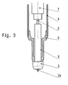
- FIG. 3 schematically shows a modified embodiment in which the ceramic insulator body 3 forms a conical-pressing dressing with the metallic housing body 5.
- the housing body 5 may be made of steel, for example, the insulator body, for example, of aluminum oxide.
Applications Claiming Priority (1)
| Application Number | Priority Date | Filing Date | Title |
|---|---|---|---|
| DE200910059649 DE102009059649B4 (de) | 2009-12-19 | 2009-12-19 | HF-Zündeinrichtung |
Publications (2)
| Publication Number | Publication Date |
|---|---|
| EP2337173A2 true EP2337173A2 (fr) | 2011-06-22 |
| EP2337173A3 EP2337173A3 (fr) | 2013-05-22 |
Family
ID=43608234
Family Applications (1)
| Application Number | Title | Priority Date | Filing Date |
|---|---|---|---|
| EP10014169.6A Withdrawn EP2337173A3 (fr) | 2009-12-19 | 2010-10-30 | Dispositif d'allumage HF |
Country Status (7)
| Country | Link |
|---|---|
| US (1) | US8863730B2 (fr) |
| EP (1) | EP2337173A3 (fr) |
| JP (1) | JP5677810B2 (fr) |
| KR (1) | KR101694685B1 (fr) |
| CN (1) | CN102122796A (fr) |
| DE (1) | DE102009059649B4 (fr) |
| RU (1) | RU2010151499A (fr) |
Cited By (3)
| Publication number | Priority date | Publication date | Assignee | Title |
|---|---|---|---|---|
| EP3379665A1 (fr) * | 2012-03-23 | 2018-09-26 | Federal-Mogul Ignition Company | Dispositif d'allumage à effet couronne à performances électriques améliorées |
| US10490982B2 (en) | 2012-03-23 | 2019-11-26 | Tenneco Inc. | Corona ignition device with improved electrical performance |
| EP2581998B1 (fr) * | 2011-10-14 | 2019-12-18 | Delphi Automotive Systems Luxembourg SA | Bougie d'allumage pour système d'allumage haute fréquence |
Families Citing this family (20)
| Publication number | Priority date | Publication date | Assignee | Title |
|---|---|---|---|---|
| US9010294B2 (en) * | 2010-04-13 | 2015-04-21 | Federal-Mogul Ignition Company | Corona igniter including temperature control features |
| WO2012091920A1 (fr) | 2010-12-14 | 2012-07-05 | Federal-Mogul Ignition Company | Igniteur à effet couronne ayant un isolateur conformé |
| CN103370530B (zh) | 2010-12-15 | 2016-09-14 | 费德罗-莫格尔点火公司 | 包括具有改进的绝缘性能的点火线圈的电晕点火器 |
| WO2012092432A1 (fr) | 2010-12-29 | 2012-07-05 | Federal-Mogul Ignition Company | Élément d'allumage à effet de couronne doté d'une commande d'espacement améliorée |
| WO2012116004A1 (fr) | 2011-02-22 | 2012-08-30 | Federal-Mogul Ignition Company | Allumeur à effet corona à efficacité énergétique améliorée |
| US8749126B2 (en) | 2011-06-27 | 2014-06-10 | Federal-Mogul Ignition Company | Corona igniter assembly including corona enhancing insulator geometry |
| DE102012108251B4 (de) * | 2011-10-21 | 2017-12-07 | Borgwarner Ludwigsburg Gmbh | Korona-Zündeinrichtung |
| JP5798054B2 (ja) * | 2012-02-01 | 2015-10-21 | 日本特殊陶業株式会社 | スパークプラグ |
| JP5820313B2 (ja) * | 2012-03-07 | 2015-11-24 | 日本特殊陶業株式会社 | 点火プラグ及び点火システム |
| JP5809585B2 (ja) * | 2012-03-07 | 2015-11-11 | 日本特殊陶業株式会社 | 点火システム |
| US10056737B2 (en) | 2012-03-23 | 2018-08-21 | Federal-Mogul Llc | Corona ignition device and assembly method |
| DE102012109762B4 (de) * | 2012-10-12 | 2014-06-05 | Borgwarner Beru Systems Gmbh | Koronazündeinrichtung mit gasdichtem HF-Steckverbinder |
| DE102012110657B3 (de) * | 2012-11-07 | 2014-02-06 | Borgwarner Beru Systems Gmbh | Koronazündeinrichtung |
| KR20150129036A (ko) * | 2013-03-15 | 2015-11-18 | 페더럴-모굴 이그니션 컴퍼니 | 코로나 점화기에 대한 마손 방지 특성 |
| DE202014101756U1 (de) | 2014-04-14 | 2014-04-30 | Borgwarner Beru Systems Gmbh | Koronazündeinrichtung |
| DE102014111684B3 (de) * | 2014-08-15 | 2015-10-01 | Borgwarner Ludwigsburg Gmbh | Koronazündeinrichtung |
| DE102015120254B4 (de) | 2015-11-23 | 2019-11-28 | Borgwarner Ludwigsburg Gmbh | Koronazündeinrichtung und Verfahren zu ihrer Herstellung |
| US10455852B2 (en) * | 2016-04-13 | 2019-10-29 | Meng-Hsiu Hsieh | Rapid defrosting tray |
| CN109952687B (zh) * | 2016-08-18 | 2021-10-15 | 天纳克公司 | 具有提高的电气性能的电晕点火装置 |
| US10879677B2 (en) * | 2018-01-04 | 2020-12-29 | Tenneco Inc. | Shaped collet for electrical stress grading in corona ignition systems |
Citations (1)
| Publication number | Priority date | Publication date | Assignee | Title |
|---|---|---|---|---|
| EP1515594A2 (fr) | 2003-09-12 | 2005-03-16 | Renault s.a.s. | Système de génération de plasma |
Family Cites Families (34)
| Publication number | Priority date | Publication date | Assignee | Title |
|---|---|---|---|---|
| US4205215A (en) * | 1976-03-31 | 1980-05-27 | U.S. Philips Corporation | Method and device for welding in a thermally ionized gas |
| JPS5693280A (en) * | 1979-11-22 | 1981-07-28 | Ngk Spark Plug Co | Thermally wide range ignition plug |
| DE3144253A1 (de) * | 1981-11-07 | 1983-05-19 | Robert Bosch Gmbh, 7000 Stuttgart | Zuendkerze fuer brennkraftmaschinen |
| US4557229A (en) * | 1982-06-07 | 1985-12-10 | Nippondenso Co., Ltd. | Ignition apparatus for internal combustion engines |
| US4774914A (en) * | 1985-09-24 | 1988-10-04 | Combustion Electromagnetics, Inc. | Electromagnetic ignition--an ignition system producing a large size and intense capacitive and inductive spark with an intense electromagnetic field feeding the spark |
| US4841925A (en) * | 1986-12-22 | 1989-06-27 | Combustion Electromagnetics, Inc. | Enhanced flame ignition for hydrocarbon fuels |
| JPH04349385A (ja) * | 1991-05-24 | 1992-12-03 | Ngk Spark Plug Co Ltd | 内燃機関用スパークプラグ |
| US5750958A (en) * | 1993-09-20 | 1998-05-12 | Kyocera Corporation | Ceramic glow plug |
| JPH11242981A (ja) * | 1997-12-09 | 1999-09-07 | Caterpillar Inc | 内部容量をもった点火プラグ |
| US6745744B2 (en) * | 2000-06-08 | 2004-06-08 | Szymon Suckewer | Combustion enhancement system and method |
| DE10155404A1 (de) * | 2001-11-10 | 2003-05-28 | Bosch Gmbh Robert | Zündkerze und Brennraumanordnung |
| US20060033411A1 (en) * | 2003-08-20 | 2006-02-16 | Lindsay Maurice E | Spark plug |
| US20050127809A1 (en) * | 2003-08-20 | 2005-06-16 | Lindsay Maurice E. | Spark plug |
| FR2878086B1 (fr) * | 2004-11-16 | 2007-03-09 | Renault Sas | Bougie a plasma radiofrequence |
| DE102004058925A1 (de) * | 2004-12-07 | 2006-06-08 | Siemens Ag | Hochfrequenz-Plasmazündvorrichtung für Verbrennungskraftmaschinen, insbesondere für direkt einspritzende Otto-Motoren |
| DE102005016125A1 (de) * | 2005-04-08 | 2006-10-12 | Robert Bosch Gmbh | Zündsystem einer Brennkraftmaschine |
| FR2884365B1 (fr) * | 2005-04-08 | 2013-10-11 | Renault Sas | Bougie multi-etincelles a chambre ouverte |
| DE102006037246A1 (de) * | 2005-08-10 | 2007-02-22 | Siemens Ag | Verfahren zum Betreiben einer Zündkerze eines Zündsystems sowie Zündsystem und geeignete Zündkerze |
| FR2892240B1 (fr) * | 2005-10-18 | 2010-10-22 | Renault Sas | Bougies d'allumage pour le moteur a combustion interne d'un vehicule automobile |
| JP2007280668A (ja) * | 2006-04-04 | 2007-10-25 | Ngk Spark Plug Co Ltd | スパークプラグ |
| DE102006037037A1 (de) * | 2006-08-08 | 2008-02-14 | Siemens Ag | Zündvorrichtung für Hochfrequenzplasmazündung |
| JP2008177142A (ja) * | 2006-12-19 | 2008-07-31 | Denso Corp | プラズマ式点火装置 |
| US7387115B1 (en) * | 2006-12-20 | 2008-06-17 | Denso Corporation | Plasma ignition system |
| JP2008171570A (ja) * | 2007-01-05 | 2008-07-24 | Denso Corp | 内燃機関の点火プラグ |
| JP4682995B2 (ja) * | 2007-03-06 | 2011-05-11 | 株式会社デンソー | プラズマ式点火装置およびその製造方法 |
| US20080308057A1 (en) * | 2007-06-18 | 2008-12-18 | Lykowski James D | Electrode for an Ignition Device |
| WO2008156035A1 (fr) * | 2007-06-19 | 2008-12-24 | Ngk Spark Plug Co., Ltd. | Bougie d'allumage à jet de plasma et dispositif d'allumage associé |
| JP5261631B2 (ja) * | 2007-07-12 | 2013-08-14 | イマジニアリング株式会社 | 点火またはプラズマ発生装置 |
| JP5045286B2 (ja) * | 2007-07-24 | 2012-10-10 | トヨタ自動車株式会社 | 内燃機関の点火装置 |
| FR2919901B1 (fr) * | 2007-08-08 | 2010-02-26 | Renault Sas | Dispositif de generation de plasma radiofrequence |
| JP5015910B2 (ja) * | 2008-03-28 | 2012-09-05 | 株式会社日本自動車部品総合研究所 | 点火装置 |
| KR20110005843A (ko) * | 2008-04-10 | 2011-01-19 | 페더럴-모굴 이그니션 컴퍼니 | 세라믹 스파크 플러그 절연체 및 그의 제조 방법 |
| US8044561B2 (en) * | 2008-08-28 | 2011-10-25 | Federal-Mogul Ignition Company | Ceramic electrode, ignition device therewith and methods of construction thereof |
| US7816845B2 (en) * | 2008-08-29 | 2010-10-19 | Federal Mogul Ignition Company | Ceramic electrode and ignition device therewith |
-
2009
- 2009-12-19 DE DE200910059649 patent/DE102009059649B4/de not_active Expired - Fee Related
-
2010
- 2010-10-30 EP EP10014169.6A patent/EP2337173A3/fr not_active Withdrawn
- 2010-11-09 JP JP2010250463A patent/JP5677810B2/ja not_active Expired - Fee Related
- 2010-12-07 KR KR1020100124070A patent/KR101694685B1/ko active IP Right Grant
- 2010-12-08 CN CN2010105785734A patent/CN102122796A/zh active Pending
- 2010-12-13 US US12/966,182 patent/US8863730B2/en not_active Expired - Fee Related
- 2010-12-16 RU RU2010151499/07A patent/RU2010151499A/ru not_active Application Discontinuation
Patent Citations (1)
| Publication number | Priority date | Publication date | Assignee | Title |
|---|---|---|---|---|
| EP1515594A2 (fr) | 2003-09-12 | 2005-03-16 | Renault s.a.s. | Système de génération de plasma |
Cited By (4)
| Publication number | Priority date | Publication date | Assignee | Title |
|---|---|---|---|---|
| EP2581998B1 (fr) * | 2011-10-14 | 2019-12-18 | Delphi Automotive Systems Luxembourg SA | Bougie d'allumage pour système d'allumage haute fréquence |
| EP3379665A1 (fr) * | 2012-03-23 | 2018-09-26 | Federal-Mogul Ignition Company | Dispositif d'allumage à effet couronne à performances électriques améliorées |
| US10490982B2 (en) | 2012-03-23 | 2019-11-26 | Tenneco Inc. | Corona ignition device with improved electrical performance |
| EP2828940B1 (fr) * | 2012-03-23 | 2020-05-06 | Federal-Mogul Ignition LLC | Dispositif d'allumage à effet couronne à fonctionnement électrique amélioré |
Also Published As
| Publication number | Publication date |
|---|---|
| KR20110070954A (ko) | 2011-06-27 |
| DE102009059649A1 (de) | 2011-06-22 |
| JP5677810B2 (ja) | 2015-02-25 |
| JP2011129511A (ja) | 2011-06-30 |
| EP2337173A3 (fr) | 2013-05-22 |
| CN102122796A (zh) | 2011-07-13 |
| DE102009059649B4 (de) | 2011-11-24 |
| RU2010151499A (ru) | 2012-06-27 |
| US20110146640A1 (en) | 2011-06-23 |
| KR101694685B1 (ko) | 2017-01-23 |
| US8863730B2 (en) | 2014-10-21 |
Similar Documents
| Publication | Publication Date | Title |
|---|---|---|
| DE102009059649B4 (de) | HF-Zündeinrichtung | |
| DE102014111684B3 (de) | Koronazündeinrichtung | |
| EP2050120B1 (fr) | Source de plasma ecr | |
| DE102010045171B4 (de) | Zünder zum Zünden eines Brennstoff-Luft-Gemisches in einer Verbrennungskammer, insbesondere in einem Verbrennungsmotor, durch Erzeugen einer Korona-Entladung | |
| EP0302474B1 (fr) | Bougie d'allumage | |
| DE102016006350A1 (de) | Zündkerze für eine Hochfrequenz-Zündanlage | |
| DE102012108251A1 (de) | Korona-Zündeinrichtung | |
| DE3404081A1 (de) | Zuendkerze | |
| WO2015163366A1 (fr) | Bougie d'allumage et douille | |
| WO2005005819A1 (fr) | Bougie d'allumage par jet de plasma | |
| WO2008017601A1 (fr) | Bougie pour allumage plasma haute fréquence | |
| DE102013101060B4 (de) | Koronazündeinrichtung | |
| DE4337119C2 (de) | VHF-Plasmaquelle | |
| DE102010022334B3 (de) | HF-Zündeinrichtung | |
| DE10360193B4 (de) | Vorrichtung zum Zünden eines Luft-Kraftstoff-Gemischs in einem Verbrennungsmotor | |
| KR20120116365A (ko) | 점화 시스템 | |
| DE102005037256A1 (de) | Vorrichtung zum Zünden eines Luft-Kraftstoff-Gemisches | |
| EP1544457A1 (fr) | Dispositif pour enflammer un melange air-carburant dans un moteur à combustion interne | |
| DE102014110432B4 (de) | Verfahren zum Zünden eines Brennstoff-Luftgemisches, Zündsystem und Glühkerze | |
| DE112016000670B4 (de) | Zündkerze für eine interne Verbrennungsmaschine | |
| DE3149676A1 (de) | Zuendvorrichtung | |
| DE102010045170B3 (de) | Korona-Zündeinrichtung und Verfahren zu ihrer Herstellung | |
| DE10360191A1 (de) | Vorrichtung zum Zünden eines Luft-Kraftstoff-Gemischs in einem Verbrennungsmotor | |
| DE10128397A1 (de) | Zündkerze | |
| DE102015226402A1 (de) | Zündvorrichtung zum Zünden eines Kraftstoff-Luft-Gemisches |
Legal Events
| Date | Code | Title | Description |
|---|---|---|---|
| PUAI | Public reference made under article 153(3) epc to a published international application that has entered the european phase |
Free format text: ORIGINAL CODE: 0009012 |
|
| AK | Designated contracting states |
Kind code of ref document: A2 Designated state(s): AL AT BE BG CH CY CZ DE DK EE ES FI FR GB GR HR HU IE IS IT LI LT LU LV MC MK MT NL NO PL PT RO RS SE SI SK SM TR |
|
| AX | Request for extension of the european patent |
Extension state: BA ME |
|
| PUAL | Search report despatched |
Free format text: ORIGINAL CODE: 0009013 |
|
| AK | Designated contracting states |
Kind code of ref document: A3 Designated state(s): AL AT BE BG CH CY CZ DE DK EE ES FI FR GB GR HR HU IE IS IT LI LT LU LV MC MK MT NL NO PL PT RO RS SE SI SK SM TR |
|
| AX | Request for extension of the european patent |
Extension state: BA ME |
|
| RIC1 | Information provided on ipc code assigned before grant |
Ipc: H01T 13/50 20060101ALI20130418BHEP Ipc: H01T 13/36 20060101AFI20130418BHEP Ipc: H01T 23/00 20060101ALI20130418BHEP |
|
| STAA | Information on the status of an ep patent application or granted ep patent |
Free format text: STATUS: THE APPLICATION IS DEEMED TO BE WITHDRAWN |
|
| 18D | Application deemed to be withdrawn |
Effective date: 20131123 |