EP2320105A2 - Kabelendehalteklammereinheit und Verfahren - Google Patents
Kabelendehalteklammereinheit und Verfahren Download PDFInfo
- Publication number
- EP2320105A2 EP2320105A2 EP10003818A EP10003818A EP2320105A2 EP 2320105 A2 EP2320105 A2 EP 2320105A2 EP 10003818 A EP10003818 A EP 10003818A EP 10003818 A EP10003818 A EP 10003818A EP 2320105 A2 EP2320105 A2 EP 2320105A2
- Authority
- EP
- European Patent Office
- Prior art keywords
- clip
- housing
- housing plate
- wall portion
- cable end
- Prior art date
- Legal status (The legal status is an assumption and is not a legal conclusion. Google has not performed a legal analysis and makes no representation as to the accuracy of the status listed.)
- Withdrawn
Links
- 230000014759 maintenance of location Effects 0.000 title claims description 18
- 238000000034 method Methods 0.000 title claims description 13
- 238000009434 installation Methods 0.000 claims description 6
- 230000006870 function Effects 0.000 description 16
- 239000004615 ingredient Substances 0.000 description 10
- 239000000463 material Substances 0.000 description 7
- 230000000712 assembly Effects 0.000 description 5
- 238000000429 assembly Methods 0.000 description 5
- 238000004519 manufacturing process Methods 0.000 description 5
- 230000007246 mechanism Effects 0.000 description 3
- 230000013011 mating Effects 0.000 description 2
- 239000002184 metal Substances 0.000 description 2
- 229910052751 metal Inorganic materials 0.000 description 2
- 229910000639 Spring steel Inorganic materials 0.000 description 1
- 230000008901 benefit Effects 0.000 description 1
- 230000015572 biosynthetic process Effects 0.000 description 1
- 239000000919 ceramic Substances 0.000 description 1
- 230000000295 complement effect Effects 0.000 description 1
- 238000010276 construction Methods 0.000 description 1
- 230000001419 dependent effect Effects 0.000 description 1
- 230000000994 depressogenic effect Effects 0.000 description 1
- 230000005489 elastic deformation Effects 0.000 description 1
- 238000005516 engineering process Methods 0.000 description 1
- 238000005755 formation reaction Methods 0.000 description 1
- 230000010354 integration Effects 0.000 description 1
- 150000002739 metals Chemical class 0.000 description 1
- 238000012986 modification Methods 0.000 description 1
- 230000004048 modification Effects 0.000 description 1
- 229920003023 plastic Polymers 0.000 description 1
- 239000004033 plastic Substances 0.000 description 1
- 230000008569 process Effects 0.000 description 1
- 238000000926 separation method Methods 0.000 description 1
Images







Classifications
-
- F—MECHANICAL ENGINEERING; LIGHTING; HEATING; WEAPONS; BLASTING
- F16—ENGINEERING ELEMENTS AND UNITS; GENERAL MEASURES FOR PRODUCING AND MAINTAINING EFFECTIVE FUNCTIONING OF MACHINES OR INSTALLATIONS; THERMAL INSULATION IN GENERAL
- F16D—COUPLINGS FOR TRANSMITTING ROTATION; CLUTCHES; BRAKES
- F16D51/00—Brakes with outwardly-movable braking members co-operating with the inner surface of a drum or the like
- F16D51/16—Brakes with outwardly-movable braking members co-operating with the inner surface of a drum or the like shaped as brake-shoes pivoted on a fixed or nearly-fixed axis
- F16D51/18—Brakes with outwardly-movable braking members co-operating with the inner surface of a drum or the like shaped as brake-shoes pivoted on a fixed or nearly-fixed axis with two brake-shoes
- F16D51/20—Brakes with outwardly-movable braking members co-operating with the inner surface of a drum or the like shaped as brake-shoes pivoted on a fixed or nearly-fixed axis with two brake-shoes extending in opposite directions from their pivots
- F16D51/22—Brakes with outwardly-movable braking members co-operating with the inner surface of a drum or the like shaped as brake-shoes pivoted on a fixed or nearly-fixed axis with two brake-shoes extending in opposite directions from their pivots mechanically actuated
-
- F—MECHANICAL ENGINEERING; LIGHTING; HEATING; WEAPONS; BLASTING
- F16—ENGINEERING ELEMENTS AND UNITS; GENERAL MEASURES FOR PRODUCING AND MAINTAINING EFFECTIVE FUNCTIONING OF MACHINES OR INSTALLATIONS; THERMAL INSULATION IN GENERAL
- F16D—COUPLINGS FOR TRANSMITTING ROTATION; CLUTCHES; BRAKES
- F16D2125/00—Components of actuators
- F16D2125/18—Mechanical mechanisms
- F16D2125/58—Mechanical mechanisms transmitting linear movement
- F16D2125/60—Cables or chains, e.g. Bowden cables
- F16D2125/62—Fixing arrangements therefor, e.g. cable end attachments
-
- Y—GENERAL TAGGING OF NEW TECHNOLOGICAL DEVELOPMENTS; GENERAL TAGGING OF CROSS-SECTIONAL TECHNOLOGIES SPANNING OVER SEVERAL SECTIONS OF THE IPC; TECHNICAL SUBJECTS COVERED BY FORMER USPC CROSS-REFERENCE ART COLLECTIONS [XRACs] AND DIGESTS
- Y10—TECHNICAL SUBJECTS COVERED BY FORMER USPC
- Y10T—TECHNICAL SUBJECTS COVERED BY FORMER US CLASSIFICATION
- Y10T24/00—Buckles, buttons, clasps, etc.
- Y10T24/39—Cord and rope holders
Definitions
- the present invention relates to a cable end retention clip assembly and method of using such, more particularly to a retention clip and method for a control cable of a brake system of a vehicle.
- the retention aspect of the design may have particular importance when the cable end is not held in-place by a tensioning force (e.g. when the brake system is fully installed in a vehicle).
- the products known in the art appear to serve this function to some extent, but do not allow for as much design flexibility as may be desirous or may require excessively tight manufacturing tolerances.
- the product taught in US Patent 6,732,840 utilizes a stationary tab that protrudes from the housing assembly as a retention device, but is believed not to be effective 100% of the time.
- the product taught in Japanese Patent JP4104811 utilizes a relatively complex clip with a snapping feature that has multiple undulations and is dependent upon a geometric relationship between a stamped hole and a formed bridge section of the housing assembly. It is believed that one skilled in the art would recognize that both examples require excessively tight manufacturing tolerances in comparison to the present invention and the present invention makes assembly of the cable assembly relatively easy and retention robust
- the present invention is directed to a unique solution to one or more of the problems discussed above. It is believed that the present invention provides a unique design and method of use of a cable end retention clip that allows for greater design flexibility in the components of the brake system and provides an easier and more robust installation/retention mechanism for the cable assembly. Particularly, the present invention allows for robust retention of the cable end when the cable assembly is not under a tensional load (e.g. control system of a brake or other system that uses such cable ends and assemblies).
- a tensional load e.g. control system of a brake or other system that uses such cable ends and assemblies.
- a clip and housing plate assembly capable of loading, unloading and retaining a cable end within the housing plate assembly including: a clip member including: a first clip rotational feature disposed on a first clip wall portion, an opposing second rotational feature disposed on a second clip wall portion, a middle clip wall portion connectively spanning between the first and second clip wall portions, and at least one clip locking feature disposed on the first clip wall portion, the second clip wall portion, or both; a housing plate member including: a first housing rotational feature disposed on a first housing wall portion, an opposing second rotational feature disposed on a second housing wall portion, and at least one housing locking feature disposed on the first housing wall portion, the second housing wall portion, or both; a lever assembly disposed between the first and second housing wall portion and rotationally connected to the housing plate member, the lever assembly including a nesting portion adapted to mate with the cable end; and wherein the clip member is disposed at least partially outside an
- the cable end comprises a barrel-type end portion with a diameter value of at least 1mm and a transverse length of at least 125% of the diameter value;
- the cable end comprises a clevis-pin type cable end;
- the cable end comprises a vertical (spherical) barrel-type cable end;
- the cable end comprises an eyelet-type cable end;
- the lever assembly is rotatably connected to the housing plate member at a rearward portion area of the housing plate member, between the first and second housing wall portions and such that at least 50% of the nesting portion is disposed forward of a middle housing wall portion, the middle housing wall portion connectively spanning between the first and second housing wall portions;
- the nesting portion comprise two opposing plates with a gapping portion therebetween with a gapping distance value at least the same as the diameter value of the cable end but not greater than the transverse length of the cable end;
- the first clip rotational feature comprises a first through hole in the clip member and the second clip rotational feature comprises
- a method of loading and retaining a cable end of a cable assembly in a clip and housing plate assembly comprising the steps of: a. providing the clip and housing plate assembly wherein the clip member is rotatably disposed towards the open loading position; b. feeding the cable end through a bottom opening between the two opposing housing plate members; c. nesting the cabin end into the nesting portion; d. rotating the clip member towards the lock position; and e. engaging the at least one clip locking feature to the at least one housing locking feature, thus loading and retaining the cable end into the clip and housing plate assembly.
- the present invention is directed to a unique solution for a cable end retention clip that allows for greater design flexibility (e.g. optimizing the system design) in the components of a brake system (e.g. drum brake assembly 14, Fig.1 ). It is contemplated that the present invention may provide an easier and more robust installation/retention mechanism for a cable assembly within the greater brake system, principally in the cases where the cable assembly is not under a tensional load when it is first assembled.
- the examples provided in this application will focus on the installation/retention mechanism in an expander component assembly of the brake system (e.g. an expander component assembly that is used in the parking brake function), although use of this inventive clipping system in other areas in the brake system is contemplated.
- the main elements of the present invention are a housing plate assembly (including a housing plate member and a lever assembly) and a clip, all adapted to allow for loading, unloading and retaining a cable end.
- the clip may be generally located outside of the housing plate assembly and rotatably attached thereto, although embodiments are contemplated where the clip (or portions thereof) is located within the housing plate assembly.
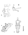
- the present invention is illustrated in a number of exemplary embodiments, as shown in Figs. 2-9B .
- the present invention, a clip and housing plate assembly 10 should be capable of ("to accommodate") loading, unloading and retaining a cable end 82 within the assembly 10 (as shown with exemplary cable assemblies 80.
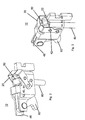
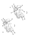
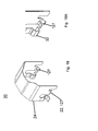
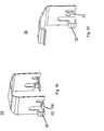
- These exemplary figures show the assembly 10 in either the "open” or “loading” ( Figs. 2 , 4 , and 6 ) position and “closed” or “locked” ( Figs. 3 , 5 , 7 , 8,and 9A-B ) position.
- the clip and housing plate assembly 10 may include a clip member 20 and a housing plate assembly 12 (comprising at least a housing plate member 40 and a lever assembly 60), wherein the clip member 20 is connectively rotationally attached to the housing plate member 40 via a first clip rotational feature 22 and a first housing rotational feature 42 (e.g. a pivoting structure and a pivot bearing structure).
- the clip member 20 may be disposed outside of an outer surface 44 of the housing plate member 40 or inside of an inner surface 46.
- the assembly 10 may also include a lever assembly 60, which may be disposed at least partially between the inner surfaces 46 of the housing plate member 40 (e.g. between the first and second housing wall portions).
- the housing plate member 40 may serve to provide a base structure for the clip and housing plate assembly 10. It may be a unitary piece (e.g. preferably a single stamped or cast piece of metal) or be an assembly of multiple pieces. The member may also provide for both rotational features and locking features, discussed in further detail below and in additional sections of the application.
- the member 40 is a unitary piece with a first housing wall portion 48, a second (opposing) housing wall portion 50 (with a gap therebetween) and a middle housing wall portion 52, connectively spanning the two wall portions.
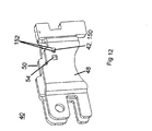
- Figs. 10 and 11 each show exemplary rotational and locking features, discussed in further detail below.
- the member 40 is an assembly with a first housing wall portion 48, a second (opposing) housing wall portion 50 (with a gap therebetween), but not including a middle housing wall portion 52.
- Fig. 10 shows yet another exemplary rotational and locking feature, discussed in further detail below.
- the housing rotational features 42, 56 may serve to provide a means to allow for rotary movement of the clip member 20 about the housing plate assembly 12.
- the features may allow for an infinitely adjustable rotation or rotation in distinct increments.
- the rotational feature may comprise structures such as round holes, other shaped holes, raised or depressed formations, cylindrical structures, or the like.
- first housing rotational feature is disposed on the first housing wall portion 40 and the second housing wall portion 50 may include a second rotational feature 56 (when necessary) generally disposed opposite of the first housing rotational feature 42.
- second rotational feature 56 may be constructed similarly or may have distinct and different designs.
- the first housing wall portion 48 may include a first housing rotational feature 42 disposed on a first housing wall portion and projecting outwardly from the outer surface.
- This feature 42 functions to provide a bearing surface that at least partially mates with a rotational feature on the clip 20, thus allowing the clip 20 and the housing 40 to rotate about each other.
- a similar rotational feature may be present on the second wall portion 50, although it not shown in the figure.
- the feature 42 may be on the inside of the housing wall portion and projecting inwardly from the inner surface (e.g. for an embodiment where the clip 20 is located inside of housing plate member).
- the feature 42 is a cylindrical structure (e.g. a three-dimensional profile) formed in the wall portion 48, although it is contemplated that this may be any number of shapes. It is preferred that the feature 42 project outwardly at least a distance that is at least equivalent to or greater than that of the thickness of the clip 20, even more preferably, projecting outward more than the distance of the thickness of the clip 20 plus the distance of at least one housing locking feature 54.
- the second rotational feature 56 (in the second housing wall portion 50) may function also as a locator for the clip 20 and may allow for some amount of play in the movement of the clip 20 (e.g. transverse movement of about 1mm or more).
- the feature 56 may be a hole or slot in the second housing wall portion, as illustrated in Fig. 4 , which is adapted to receive a second rotational feature of the clip 20 (e.g. a tab as illustrated in Figs. 5 and 6 ) that does not precisely match the shape of the feature 56. It is believed that having this 'play' in the rotational features may allow for greater manufacturing tolerances on each relevant component of the system (e.g. the clip 20 and the housing assembly 12 do not have to match exactly).
- the first and second rotational features 42, 56 are shaped slots 150 that allow for limited movement of the clip member 20 (e.g. from a loading position to a locked position).
- These slots 150 include a pair of pivot bearing points (or surfaces) 152, on which the rotational features of the clip 20 pivot in this example, the rotational features of the clip member 20 are turned-in tabs 126 (shown in Fig. 16 and 17 ), discussed in further detail in the clip section below.
- the first and second rotational features 42, 56 are circular holes 160, which serve as mating surfaces for the rotational features of the clip 20.
- the rotational features of the clip member 20 are turned-in split tabs 127 (shown in Fig. 18 and 16A ), discussed in further detail in the clip section below. It is believed that this embodiment may be preferred due to the relative ease of forming and maintaining a generally circular hole in the housing plate member 40 (e.g. via a round punch).
- first housing wall portion 48, the second housing wall portion 50, or both may also include at least one housing locking feature 54.
- This locking feature 54 functions to provide a positive rotational locking function in conjunction with the locking feature of the clip.
- the housing locking feature 54 may comprise any structure that functions to keep the housing plate member 40 and the clip member 20 from rotating with respect to one another. It is preferred that the locking feature be designed such that relatively high rotational force (e.g. greater than about 10 Newtons) is applied to the top of the clip 20. It is contemplated and preferred that this feature 54 may include an arcuate surface feature (e.g. having a three-dimensional profile) or may be a through-hole in the first, second, or both wall portions 48, 50 although it is contemplated that this may be any number of shapes.
- the feature 54 is a outwardly projecting surface that projects outwardly (e.g. about 1 mm to about 12mm) from the outer surface of the wall and at least partially conforms to a locking feature of the clip 20. It is contemplated that the outwardly projecting surface may be circular, tear drop, square, rectangular, or of any geometric shape. In a preferred embodiment, the outwardly projecting surface is a circular shape. It should be noted that the feature 54 may project inwardly, especially in the case where the clip 20 is located inside of the housing (e.g. clip in Fig. 8 )
- the feature 54 is a through-hole. It is contemplated that the through-hole may be circular, square, rectangular, or of any geometric shape. In a preferred embodiment, the through-hole is a square or rectangular shape that conforms at least partially to the mating shape of a square locking feature of the clip, discussed in further detail below.
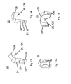
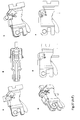
- the clip member 20, when assembled to the housing plate assembly 12 functions to allow for loading, unloading and retaining the cable end 82 within the housing plate assembly 12. It may be generally disposed outside the outer surface (or inside the inside surface) of the housing plate member 40 and rotatably connected thereto. Generally, the clip 20 may have any shape which allows it to perform the recited function, including a "U" shape, "J" shape, or "C” shape, although other local geometric features are possible. Exemplary clip members are shown in Figs. 13-20 . It is contemplated that during installation or removal of the cable end 82, the clip member 20 is rotatably disposed towards a forward (open) loading position, for example as illustrated in Figs. 26A-E and Figs.
- the clip 20 is rotatably disposed towards a locked retention position, for example as illustrated in Figs. 26F , 27E-F , and 28B . In this locked position the at least one housing locking feature 54 and an at least one clip locking feature 32 are engaged.
- the clip member 20 is constructed of a material that has some geometric memory or elastic deformation. In other words, the material returns to or nearly to its original shape after it has been subjected to a physical stress (e.g. as would occur during loading of the clip onto the housing or when the clip is moved to and from the locked retention position.
- the clip is constructed of a spring steel, although other materials that meet the above "memory" requirements are contemplated. It is contemplated that the distance between the first clip wall portion 24, and the opposing second clip wall portion 28 is about equivalent to (e.g. +/- about 10%) the outside width of the housing plate assembly 12, at least in the areas where they interact.
- the clip member 20 can be generally defined as including a first clip rotational feature 22 disposed on a first clip wall portion 24, an opposing second rotational feature 26 disposed on a second clip wall portion 28, a middle clip wall portion 30 connectively spanning between the first and second clip wall portions, and at least one clip locking feature 32 disposed on the first clip wall portion, the second clip wall portion, or both. It is contemplated that any combination of the clip locking and rotational features as illustrated in the figures and as described below may be used to provide the needed functionality. It is also contemplated that the clip 20 may only have a first clip wall portion 24 and a middle clip wall portion 30, for example as shown in Figs. 9A-B and 20 .
- the relative dimensions of the clip member 20 are such that when the clip and housing plate assembly is the lock position, the middle clip wall portion 30 is disposed above the nesting portion 64 and the cable end 82.
- the middle clip wall portion 30 has a fore-aft length C L and profile that when in the locked position, provides for a gapping distance between any part of the housing plate member 40 or of the nesting portion 64(discussed in the lever assembly section below) that is no more than about 100% that of that of a cable end diameter value 84 (or height value 90).
- the clip member (locked position) is disposed above an upper edge portion of the housing plate member 40 or of the nesting portion 64 with no more than an axial distance equivalent of about 175% of that of a cable end diameter value 84. More preferably, the axial distance is no more than about 150%, and most preferably no more than about 125% of that of a cable end diameter value 84. It is also preferable that the length C L and profile is small enough such that the clip 20, when in the forward loading position (e.g. Fig. 23A ) a gap L G is created allowing the cable end to pass.
- this loading gap L G is at least equivalent to a transverse length 86 of the cable end 82, more preferably about 125% of the transverse length 86, and most preferably about 150% of the transverse length 86.
- the length C L and profile may be locally larger (e.g. extension tab 31) and may be particularly useful in the case where the housing plate member 40 does not include a middle housing wall portion 52, for example as illustrated in Fig. 25 .
- the extension tab may also function as a stopper for the rotation of the lever assembly 60.
- the middle clip wall portion 30 may also include other localized geometric features, for example: dimples; bent tabs or walls; or holes, which may aid in retaining the cable end 82 or may serve other desired functions.
- the clip rotational features 22, 26 may serve to provide a means to allow for rotary movement of the clip member 20 about the housing plate assembly 12.
- the features 22, 26 may allow for an infinitely adjustable rotation or rotation in distinct increments. There are numerous configurations of these features 22, 26 contemplated and the examples discussed below should not be considered as limiting. It is contemplated that the clip rotational feature is disposed on the first clip wall portion 24 and the second clip wall portion 28 may include a second rotational feature 26 generally disposed opposite of the first clip rotational feature 22.
- These features 22, 26 may be constructed similarly or may have distinct and different designs. It should be apparent to one skilled in the art which clip rotational feature can function with which housing rotational feature and which cannot. It should also be apparent that clip rotational feature 22 and 26 could be similar in construction to each other or different from each other.
- the clip rotational features are circular holes that are adapted to mate to the rotational features of the housing rotational features 42, 56.
- the clip rotational features are shown as inwardly turned tabs 126.
- the inwardly turned tabs 126 are adapted to rotate within the slots 150 on the pivot bearing points (or surfaces) 152. It is contemplated that these tabs 126 may be a single material thickness (e.g. as illustrated In Figs. 15 , 16, and 17 ) or be multiple material thicknesses (e.g. as a turned over tabs 126 as illustrated in Fig. 16A ). It may also be an outwardly turned tab 126 as shown in Fig. 19 .
- the clip rotational features are shown as inwardly turned split- tabs 127. These split tabs 127 adapted to rotate within the circular holes 160 of the housing 40. It may also be outwardly turned split-tabs 127, not shown.
- either of the clip wall portions 24, 28, or both include at least one locking feature 32.
- This feature 32 may serve to "lock" the clip 20 in place when the clip 20 is rotated to the locked position (e.g. Figs. 26F , 27E-F , and 28B ), thus preventing clip rotation unless a relatively high rotational force (e.g. greater than about 10 Newtons, but not so great that you damage the clip such that it no longer can provide its intended function) is applied to the top of the clip 20.
- a relatively high rotational force e.g. greater than about 10 Newtons, but not so great that you damage the clip such that it no longer can provide its intended function
- the force required to move the clip 20 from the open position to the locked position is less than that of moving it out of the locked position.
- the force required to move the clip 20 out of the locked position e.g.
- the clip locking feature 32 (one side only), is a through-hole that is adapted to mate with the at least one housing locking feature 54.
- Fig. 13A two such locking features 32, on opposing walls are illustrated.
- the clip 20 may also include a ramp portion 29 which may provide a lead-in function when the clip 20 is rotated towards the locked position.
- the clip locking feature 32 (one side only), is a pocket 27 formed in the wall portion 24, again adapted to mate with the at least one housing locking feature 54.
- the clip locking feature 32 is an inwardly turned tab (both sides).
- the clip locking feature 32 is a rounded locking tab that has a shape that generally complements the preferred locking feature 54 of the housing plate member 40.
- a lever assembly 60 is part of the housing plate assembly 12 and may be at least partially disposed between an inner surfaces 46 of the housing plate member 40 and rotationally attached thereto. This lever assembly 60 functions to translate the movement of the cable assembly 80 (into the brake 14) and provide a nesting place (e.g. nesting portion 64) for the cable end 82. It is contemplated that the lever assembly 60 may be rotatably connected (e.g. via a pivot means) to the housing plate member 40 at or near a rearward portion area of the housing plate member 40 via a fastener (e.g. rivet 62, see Fig. 25 ).
- a fastener e.g. rivet 62, see Fig. 25
- the lever assembly 60 may be a single piece or a multiple piece assembly, but preferably includes a nesting portion 64 (e.g. a single or multi-pronged hook).
- a nesting portion 64 e.g. a single or multi-pronged hook.
- An exemplary multi-pronged lever assembly 60 is illustrated in Fig. 21 , a single hook version is not shown.
- the nesting portion 64 functions to hold the cable end 82 of the cable assembly 80.
- the shape or profile (e.g. a hook or bent post) of the nesting portion 64 should at least partially complement that of the cable end 82.
- the nesting portion 64 may be a single hook (e.g. for an eyelet-type cable end) or a multi-pronged hook (e.g. for a horizontal barrel-type cable end, a clevis-pin type cable end, or a vertical barrel-type cable end). It is also contemplated that the nesting portion is open towards the top (e.g. in a "U" shape) such that the cable end 82 can move freely in and out of it.
- the nesting portion 64 may be constructed of two opposing plates with a gapping portion 66 therebetween.
- the gapping portion 66 with a gapping distance value at least the same as the diameter value 84 of the cable end 82 but not greater than the transverse length 86 of the cable end 82 (for the case of a horizontal barrel-type cable end or a clevis-pin type cable end).
- the nesting portion 64 may be constructed of two opposing plates with a gapping portion 66 therebetween.
- the gapping portion 66 with a gapping distance value less than the transverse length 86 of the cable end 82 (for the case of a vertical (or spherical) barrel-type cable end).
- the nesting portion is a single plate over which an eyelet-type cable end may be loaded (although you could use an eyelet-type with a lever assembly 60 that has two opposing plated).
- the nesting portion 64 is disposed such that at least about 50% of it is forward of the middle housing wall portion 52, more preferably at least about 75%, and most preferably wherein the entire nesting portion is disposed forward of the middle housing wall portion 52, at least in the area (e.g. plus or minus about 15mm) surrounding where the cable end 82 mates with the nesting portion 64.
- the cable assembly 80 and cable end 82 are of the type typically used in braking systems. It is contemplated that the cable assembly may have an end portion that enables the end of the cable assembly 82 to be held in place (including loading and unloading) in the housing 40 (e.g. in the nesting portion 64) by any known end which achieves this.
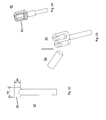
- Examples of such ends 82 include a horizontal barrel-type cable end, a clevis-pin type cable end, a vertical (spherical) barrel-type cable end, or an eyelet-type cable end, all of which are commonly known in the industry (as illustrate in Figs. 22, 23 , 28D , and 24 respectively).
- the cable end 82 is a barrel-type end portion (or a clevis-pin type cable end) with a diameter value 84 of at least 4mm and a transverse length 86 of at least 125% of the diameter value.
- the cable end 82 is a vertical (or spherical barrel-type cable end with a height value 90 of at least 4mm and a transverse length 86 of at least 125% of the diameter value.
- a method of loading and retaining the cable end of the cable assembly in the clip and housing plate assembly may include the steps of: a. providing the clip and housing plate assembly wherein the clip member is rotatably disposed towards the forward loading position (or rearward position); b. feeding the cable end through a bottom opening between the two opposing housing plate members (through and past the gapping portion of the nesting portion wherein the cable end is rotationally disposed such that it fits though the gapping portion or a gap (e.g. forward gap 41) between the housing and the lever assembly); c.
- the member 40 is a unitary piece with a first housing wall portion 48, a second (opposing) housing wall portion 50 (with a gap therebetween) and a middle housing wall portion 52, connectively spanning the two wall portions.
- an exemplary lever assembly 60 that is connectively (and rotationally via a pivot 62) disposed (at least partially) inside of the inner surface 46 of the member 40, forming the housing plate assembly 12. The cable assembly is fed up through the gapping portion of the lever assembly which allows for the loading of a cable end 82.
- the member 40 is a unitary piece with a first housing wall portion 48, a second (opposing) housing wall portion 50 (with a gap therebetween) and a middle housing wall portion 52, connectively spanning the two wall portions.
- an exemplary lever assembly 60 that is connectively (and rotationally via a pivot 62) disposed (at least partially) inside of the inner surface 46 of the member 40, forming the housing plate assembly 12.
- any numerical values recited in the above application include all values from the lower value to the upper value in increments of one unit provided that there is a separation of at least 2 units between any lower value and any higher value.
- the amount of a component or a value of a process variable such as, for example, temperature, pressure, time and the like is, for example, from 1 to 90, preferably from 20 to 80, more preferably from 30 to 70, it is intended that values such as 15 to 85, 22 to 68, 43 to 51, 30 to 32 etc. are expressly enumerated in this specification.
- one unit is considered to be 0.0001, 0.001, 0.01 or 0.1 as appropriate.
Landscapes
- Engineering & Computer Science (AREA)
- General Engineering & Computer Science (AREA)
- Mechanical Engineering (AREA)
- Mechanical Control Devices (AREA)
- Braking Arrangements (AREA)
Applications Claiming Priority (2)
| Application Number | Priority Date | Filing Date | Title |
|---|---|---|---|
| US25826509P | 2009-11-05 | 2009-11-05 | |
| US12/727,563 US20110100772A1 (en) | 2009-11-05 | 2010-03-19 | Cable end retention clip assembly and method |
Publications (2)
| Publication Number | Publication Date |
|---|---|
| EP2320105A2 true EP2320105A2 (de) | 2011-05-11 |
| EP2320105A3 EP2320105A3 (de) | 2012-01-25 |
Family
ID=43365251
Family Applications (1)
| Application Number | Title | Priority Date | Filing Date |
|---|---|---|---|
| EP10003818A Withdrawn EP2320105A3 (de) | 2009-11-05 | 2010-04-09 | Kabelendehalteklammereinheit und Verfahren |
Country Status (2)
| Country | Link |
|---|---|
| US (1) | US20110100772A1 (de) |
| EP (1) | EP2320105A3 (de) |
Families Citing this family (5)
| Publication number | Priority date | Publication date | Assignee | Title |
|---|---|---|---|---|
| WO2013039781A2 (en) | 2011-09-16 | 2013-03-21 | Adc Telecommunications, Inc. | Systems and methods for the management of fiber optic cables |
| US9360648B2 (en) * | 2011-09-16 | 2016-06-07 | Commscope Technologies Llc | Systems and methods for the management of fiber optic cables |
| IT201600105859A1 (it) | 2016-10-20 | 2018-04-20 | Freni Brembo Spa | Assieme di attuazione di un freno di stazionamento |
| IT201600128706A1 (it) | 2016-12-20 | 2018-06-20 | Freni Brembo Spa | Dispositivo di regolazione del gioco di un freno di stazionamento |
| CN109695641B (zh) * | 2017-10-24 | 2024-01-23 | 广东洛梵狄智能科技有限公司 | 一种轮毂锁和自行车 |
Citations (4)
| Publication number | Priority date | Publication date | Assignee | Title |
|---|---|---|---|---|
| US6234281B1 (en) | 2000-11-07 | 2001-05-22 | Robert Bosch Corporation | Attachment of a brake cable with an actuator of a parking brake |
| US6679354B1 (en) | 2003-01-28 | 2004-01-20 | Robert Bosch Corporation | Actuator mechanism for drum in hat brake |
| US6732840B2 (en) | 2001-06-08 | 2004-05-11 | Nisshinbo Industries Inc. | Brake cable connecting apparatus for a drum brake device |
| JP4104811B2 (ja) | 2000-06-08 | 2008-06-18 | 曙ブレーキ工業株式会社 | 機械式ドラムブレーキのレバーとケーブルの接続構造 |
Family Cites Families (30)
| Publication number | Priority date | Publication date | Assignee | Title |
|---|---|---|---|---|
| US3074675A (en) * | 1961-06-29 | 1963-01-22 | William F Brown | Retainer for wires |
| US4073200A (en) * | 1976-08-09 | 1978-02-14 | Allis-Chalmers Corporation | Cable retainer |
| KR860002822Y1 (ko) * | 1983-12-27 | 1986-10-18 | 닛신 고오교오 가부시기 가이샤 | 기계작동식 드럼 브레이크 장치 |
| ES2042854T3 (es) * | 1989-04-17 | 1993-12-16 | Lucas Ind Plc | Freno de tambor para un vehiculo de motor con un freno de estacionamiento. |
| WO1991015685A1 (de) * | 1990-03-31 | 1991-10-17 | Alfred Teves Gmbh | Bremsseilbefestigung für eine feststellbremse, insbesondere für eine duo-servo-topfhandbremse |
| US5010781A (en) * | 1990-05-29 | 1991-04-30 | Chrysler Corporation | Retaining assembly for throttle and speed control cables |
| US5142935A (en) * | 1991-10-25 | 1992-09-01 | Allied-Signal Inc. | Parking brake lever cable retainer |
| US5360086A (en) * | 1993-12-07 | 1994-11-01 | Alliedsignal Inc. | Drum brake with cam operated parking brake lever |
| US5662004A (en) * | 1995-01-19 | 1997-09-02 | Grand Haven Stamped Products, Div. Of Jsj Corporation | Vehicle shift cable connection |
| US5720367A (en) * | 1995-08-23 | 1998-02-24 | Kelsey-Hayes Company | Parking and emergency brake operating mechanism for dual mode drum brake assemlby |
| JPH1042445A (ja) * | 1996-07-19 | 1998-02-13 | Mitsui Mining & Smelting Co Ltd | ケーブル端末の取付構造 |
| JP4468536B2 (ja) * | 1999-04-01 | 2010-05-26 | 日清紡ホールディングス株式会社 | 操作ケーブルの接続装置 |
| JP4397080B2 (ja) * | 1999-11-02 | 2010-01-13 | 日清紡ホールディングス株式会社 | 操作ケーブルの接続装置 |
| JP2001254771A (ja) * | 2000-03-08 | 2001-09-21 | Nisshinbo Ind Inc | ドラムブレーキのブレーキケーブル接続装置 |
| JP4371286B2 (ja) * | 2000-04-12 | 2009-11-25 | 日清紡ホールディングス株式会社 | 操作ケーブルの接続装置 |
| JP2001323955A (ja) * | 2000-05-18 | 2001-11-22 | Nisshinbo Ind Inc | ドラムブレーキのブレーキケーブル接続装置 |
| US6776554B2 (en) * | 2001-10-25 | 2004-08-17 | Delphi Technologies, Inc. | Cable attachment and method of assembling same |
| US20030121736A1 (en) * | 2001-12-28 | 2003-07-03 | Avid, L.L.C. | Master cylinder lever for a hydraulic disc brake having a backpack reservoir |
| JP4015437B2 (ja) * | 2002-02-18 | 2007-11-28 | 株式会社大井製作所 | コントロールケーブルの取付装置 |
| JP4096105B2 (ja) * | 2002-09-17 | 2008-06-04 | 日清紡績株式会社 | ブレーキケーブルの接続装置 |
| US7210658B2 (en) * | 2003-01-30 | 2007-05-01 | Jose Francisco Carrera | Gated retainer |
| JP4242659B2 (ja) * | 2003-02-12 | 2009-03-25 | 日清紡績株式会社 | ドラムブレーキのブレーキケーブル接続装置 |
| JP2004293643A (ja) * | 2003-03-26 | 2004-10-21 | Hosei Brake Ind Ltd | ケーブル直角引きパーキングブレーキ |
| JP2006105301A (ja) * | 2004-10-06 | 2006-04-20 | Nisshinbo Ind Inc | ブレーキケーブル接続装置 |
| US7730805B2 (en) * | 2005-01-13 | 2010-06-08 | Dura Global Technologies, Llc | Motor vehicle park brake cable and eyelet |
| JP4186012B2 (ja) * | 2005-08-09 | 2008-11-26 | 日清紡績株式会社 | 機械式ブレーキ作動装置 |
| JP4721222B2 (ja) * | 2006-01-11 | 2011-07-13 | 日清紡ホールディングス株式会社 | 機械式ブレーキ作動装置 |
| US7490702B1 (en) * | 2007-12-20 | 2009-02-17 | Kelsey-Hayes Company | Parking and emergency brake actuator for a drum-in-hat disc brake assembly |
| US8267227B2 (en) * | 2008-07-22 | 2012-09-18 | Akebono Brake Corporation | Lever assembly featuring blind cable assembly |
| JP5342988B2 (ja) * | 2008-12-16 | 2013-11-13 | 日清紡ホールディングス株式会社 | ドラムブレーキの機械式ブレーキ作動装置 |
-
2010
- 2010-03-19 US US12/727,563 patent/US20110100772A1/en not_active Abandoned
- 2010-04-09 EP EP10003818A patent/EP2320105A3/de not_active Withdrawn
Patent Citations (4)
| Publication number | Priority date | Publication date | Assignee | Title |
|---|---|---|---|---|
| JP4104811B2 (ja) | 2000-06-08 | 2008-06-18 | 曙ブレーキ工業株式会社 | 機械式ドラムブレーキのレバーとケーブルの接続構造 |
| US6234281B1 (en) | 2000-11-07 | 2001-05-22 | Robert Bosch Corporation | Attachment of a brake cable with an actuator of a parking brake |
| US6732840B2 (en) | 2001-06-08 | 2004-05-11 | Nisshinbo Industries Inc. | Brake cable connecting apparatus for a drum brake device |
| US6679354B1 (en) | 2003-01-28 | 2004-01-20 | Robert Bosch Corporation | Actuator mechanism for drum in hat brake |
Also Published As
| Publication number | Publication date |
|---|---|
| EP2320105A3 (de) | 2012-01-25 |
| US20110100772A1 (en) | 2011-05-05 |
Similar Documents
| Publication | Publication Date | Title |
|---|---|---|
| EP3783177B1 (de) | Fahrzeugtürfeststeller | |
| JP5663751B2 (ja) | 保持構造を有する圧縮制限装置 | |
| US20110100772A1 (en) | Cable end retention clip assembly and method | |
| JP5263168B2 (ja) | 車両用シートスライド装置 | |
| US8672385B2 (en) | Seat locking device | |
| CN110435496B (zh) | 具有凸轮组件的支撑组件 | |
| US5975784A (en) | Bolt action ring binder | |
| JP5921755B2 (ja) | ロックユニットと車両シート | |
| US20070283542A1 (en) | Method of Manufacturing a Ring Mechanism | |
| US7731313B2 (en) | Locating structure for slide rail | |
| US7096539B2 (en) | Shim assembly for releasably engaging a hinge assembly | |
| EP2067943A1 (de) | Ventiltrieb und Ventilhebeleinrichtung | |
| US20080279490A1 (en) | Sliding friction reducer | |
| EP3194804A1 (de) | Scheibenbremse für ein nutzfahrzeug | |
| EP2529089B1 (de) | Nockenwellenversteller | |
| US8657349B2 (en) | Latch assembly for a vehicle | |
| KR20070061424A (ko) | 서류 등의 철하는 도구 | |
| CN102018336B (zh) | 自锁式隐形拉头 | |
| EP2705260B1 (de) | Verbindungsvorrichtung für möbelstücke und möbelartikel | |
| DE202009002003U1 (de) | Beschlag und Wandschrank | |
| EP1776886B1 (de) | Schnallenvorrichtung | |
| EP3408475B1 (de) | Schliessteil und verfahren zum herstellen eines schliessteils | |
| JP3124552U (ja) | 蝶番構造 | |
| DE3344041A1 (de) | Sicherheitsgurtschloss | |
| CN1632268B (zh) | 双钩型门锁构造(三) |
Legal Events
| Date | Code | Title | Description |
|---|---|---|---|
| PUAI | Public reference made under article 153(3) epc to a published international application that has entered the european phase |
Free format text: ORIGINAL CODE: 0009012 |
|
| AK | Designated contracting states |
Kind code of ref document: A2 Designated state(s): AT BE BG CH CY CZ DE DK EE ES FI FR GB GR HR HU IE IS IT LI LT LU LV MC MK MT NL NO PL PT RO SE SI SK SM TR |
|
| AX | Request for extension of the european patent |
Extension state: AL BA ME RS |
|
| PUAL | Search report despatched |
Free format text: ORIGINAL CODE: 0009013 |
|
| AK | Designated contracting states |
Kind code of ref document: A3 Designated state(s): AT BE BG CH CY CZ DE DK EE ES FI FR GB GR HR HU IE IS IT LI LT LU LV MC MK MT NL NO PL PT RO SE SI SK SM TR |
|
| AX | Request for extension of the european patent |
Extension state: AL BA ME RS |
|
| RIC1 | Information provided on ipc code assigned before grant |
Ipc: F16G 11/10 20060101ALI20111219BHEP Ipc: F16D 65/14 20060101ALI20111219BHEP Ipc: F16D 51/22 20060101AFI20111219BHEP |
|
| STAA | Information on the status of an ep patent application or granted ep patent |
Free format text: STATUS: THE APPLICATION IS DEEMED TO BE WITHDRAWN |
|
| 18D | Application deemed to be withdrawn |
Effective date: 20120726 |