EP2317334B1 - Procédé et programme pour afficher une image radar et dispositif de traitement de signal de détection d'objets cibles - Google Patents
Procédé et programme pour afficher une image radar et dispositif de traitement de signal de détection d'objets cibles Download PDFInfo
- Publication number
- EP2317334B1 EP2317334B1 EP10188510.1A EP10188510A EP2317334B1 EP 2317334 B1 EP2317334 B1 EP 2317334B1 EP 10188510 A EP10188510 A EP 10188510A EP 2317334 B1 EP2317334 B1 EP 2317334B1
- Authority
- EP
- European Patent Office
- Prior art keywords
- scan
- data
- target object
- module
- reception
- Prior art date
- Legal status (The legal status is an assumption and is not a legal conclusion. Google has not performed a legal analysis and makes no representation as to the accuracy of the status listed.)
- Active
Links
- 238000001514 detection method Methods 0.000 title claims description 37
- 238000000034 method Methods 0.000 title claims description 15
- 230000004044 response Effects 0.000 claims 2
- 230000006870 function Effects 0.000 description 9
- 230000000875 corresponding effect Effects 0.000 description 8
- 238000010586 diagram Methods 0.000 description 5
- 230000008901 benefit Effects 0.000 description 4
- 230000005540 biological transmission Effects 0.000 description 4
- 238000006243 chemical reaction Methods 0.000 description 4
- 230000009471 action Effects 0.000 description 3
- 238000002592 echocardiography Methods 0.000 description 3
- 230000008569 process Effects 0.000 description 3
- 206010047571 Visual impairment Diseases 0.000 description 2
- 230000008859 change Effects 0.000 description 2
- 230000002596 correlated effect Effects 0.000 description 2
- 238000012986 modification Methods 0.000 description 2
- 230000004048 modification Effects 0.000 description 2
- 230000001629 suppression Effects 0.000 description 2
- 238000004364 calculation method Methods 0.000 description 1
- 238000013500 data storage Methods 0.000 description 1
- 239000000284 extract Substances 0.000 description 1
- 238000007781 pre-processing Methods 0.000 description 1
- 230000002265 prevention Effects 0.000 description 1
- 238000003672 processing method Methods 0.000 description 1
- 230000000644 propagated effect Effects 0.000 description 1
- 230000000630 rising effect Effects 0.000 description 1
Images


Classifications
-
- G—PHYSICS
- G01—MEASURING; TESTING
- G01S—RADIO DIRECTION-FINDING; RADIO NAVIGATION; DETERMINING DISTANCE OR VELOCITY BY USE OF RADIO WAVES; LOCATING OR PRESENCE-DETECTING BY USE OF THE REFLECTION OR RERADIATION OF RADIO WAVES; ANALOGOUS ARRANGEMENTS USING OTHER WAVES
- G01S7/00—Details of systems according to groups G01S13/00, G01S15/00, G01S17/00
- G01S7/02—Details of systems according to groups G01S13/00, G01S15/00, G01S17/00 of systems according to group G01S13/00
- G01S7/28—Details of pulse systems
- G01S7/285—Receivers
- G01S7/292—Extracting wanted echo-signals
-
- G—PHYSICS
- G01—MEASURING; TESTING
- G01S—RADIO DIRECTION-FINDING; RADIO NAVIGATION; DETERMINING DISTANCE OR VELOCITY BY USE OF RADIO WAVES; LOCATING OR PRESENCE-DETECTING BY USE OF THE REFLECTION OR RERADIATION OF RADIO WAVES; ANALOGOUS ARRANGEMENTS USING OTHER WAVES
- G01S13/00—Systems using the reflection or reradiation of radio waves, e.g. radar systems; Analogous systems using reflection or reradiation of waves whose nature or wavelength is irrelevant or unspecified
- G01S13/66—Radar-tracking systems; Analogous systems
- G01S13/72—Radar-tracking systems; Analogous systems for two-dimensional tracking, e.g. combination of angle and range tracking, track-while-scan radar
-
- G—PHYSICS
- G01—MEASURING; TESTING
- G01S—RADIO DIRECTION-FINDING; RADIO NAVIGATION; DETERMINING DISTANCE OR VELOCITY BY USE OF RADIO WAVES; LOCATING OR PRESENCE-DETECTING BY USE OF THE REFLECTION OR RERADIATION OF RADIO WAVES; ANALOGOUS ARRANGEMENTS USING OTHER WAVES
- G01S13/00—Systems using the reflection or reradiation of radio waves, e.g. radar systems; Analogous systems using reflection or reradiation of waves whose nature or wavelength is irrelevant or unspecified
- G01S13/02—Systems using reflection of radio waves, e.g. primary radar systems; Analogous systems
- G01S13/50—Systems of measurement based on relative movement of target
- G01S13/52—Discriminating between fixed and moving objects or between objects moving at different speeds
- G01S13/522—Discriminating between fixed and moving objects or between objects moving at different speeds using transmissions of interrupted pulse modulated waves
- G01S13/524—Discriminating between fixed and moving objects or between objects moving at different speeds using transmissions of interrupted pulse modulated waves based upon the phase or frequency shift resulting from movement of objects, with reference to the transmitted signals, e.g. coherent MTi
- G01S13/5244—Adaptive clutter cancellation
-
- G—PHYSICS
- G01—MEASURING; TESTING
- G01S—RADIO DIRECTION-FINDING; RADIO NAVIGATION; DETERMINING DISTANCE OR VELOCITY BY USE OF RADIO WAVES; LOCATING OR PRESENCE-DETECTING BY USE OF THE REFLECTION OR RERADIATION OF RADIO WAVES; ANALOGOUS ARRANGEMENTS USING OTHER WAVES
- G01S13/00—Systems using the reflection or reradiation of radio waves, e.g. radar systems; Analogous systems using reflection or reradiation of waves whose nature or wavelength is irrelevant or unspecified
- G01S13/88—Radar or analogous systems specially adapted for specific applications
- G01S13/89—Radar or analogous systems specially adapted for specific applications for mapping or imaging
-
- G—PHYSICS
- G01—MEASURING; TESTING
- G01S—RADIO DIRECTION-FINDING; RADIO NAVIGATION; DETERMINING DISTANCE OR VELOCITY BY USE OF RADIO WAVES; LOCATING OR PRESENCE-DETECTING BY USE OF THE REFLECTION OR RERADIATION OF RADIO WAVES; ANALOGOUS ARRANGEMENTS USING OTHER WAVES
- G01S7/00—Details of systems according to groups G01S13/00, G01S15/00, G01S17/00
- G01S7/02—Details of systems according to groups G01S13/00, G01S15/00, G01S17/00 of systems according to group G01S13/00
- G01S7/28—Details of pulse systems
- G01S7/285—Receivers
- G01S7/292—Extracting wanted echo-signals
- G01S7/2923—Extracting wanted echo-signals based on data belonging to a number of consecutive radar periods
- G01S7/2927—Extracting wanted echo-signals based on data belonging to a number of consecutive radar periods by deriving and controlling a threshold value
-
- G—PHYSICS
- G01—MEASURING; TESTING
- G01S—RADIO DIRECTION-FINDING; RADIO NAVIGATION; DETERMINING DISTANCE OR VELOCITY BY USE OF RADIO WAVES; LOCATING OR PRESENCE-DETECTING BY USE OF THE REFLECTION OR RERADIATION OF RADIO WAVES; ANALOGOUS ARRANGEMENTS USING OTHER WAVES
- G01S7/00—Details of systems according to groups G01S13/00, G01S15/00, G01S17/00
- G01S7/02—Details of systems according to groups G01S13/00, G01S15/00, G01S17/00 of systems according to group G01S13/00
- G01S7/36—Means for anti-jamming, e.g. ECCM, i.e. electronic counter-counter measures
Definitions
- the present invention relates mainly to a target object detection signal processing device, and, more specifically, to the target object detection signal processing device, which is used for target object detection, for suppressing an unnecessary signal contained in a signal received by a radar device, a scanning sonar or the like, and to a method and program for displaying a radar image.
- a radar device for performing the scan-to-scan correlation processing is disclosed in the following publications, for example.
- JPA 2003-315439 discloses a configuration including a correlation processing memory that independently stores moving target objects, respectively, and for performing surface correlation processing for every correlation processing memory (scan-to-scan correlation processing). Therefore, this related art can accurately discriminate moving target objects while removing noises, such as sea surface reflections.
- JPA H08-136641 discloses a configuration including a recursive digital filter, and for changing and setting a filter characteristic in real time according to a change in echo signal. Therefore, this related art can prevent a target object signal from being suppressed when suppressing a clutter signal.
- JPA 2003-315439 must provide a memory for every moving target object. For this reason, if the scan-to-scan correlation processing is performed for many target objects, a required memory capacity will be enormous. In addition, there is a problem that a calculation load will also increase.
- JPA H08-136641 also determines a rising edge or a trailing edge of the signal, and determines whether the signal is a target object or a clutter. Therefore, complicated processing in which a coefficient of the recursive digital filter is changed based on the determination result must be performed.
- JPA 2002-139562 needs to track each moving target object in advance by ARPA (Automatic Collision Prevention Assistance Device) or the like before performing the scan-to-scan correlation processing.
- ARPA Automatic Collision Prevention Assistance Device
- the present invention is made in the view of situations described above.
- the reception data output module acquires the reception data indicative of the signal level of the signal received by the antenna.
- the device discharges from an antenna the electromagnetic wave generated in an electromagnetic wave generator, such as a magnetron, and propagated through a waveguide.
- the discharged electromagnetic wave is reflected on the target object, such as another ship or a land.
- the reflected echo signal is received by the antenna, and based on a received timing, an azimuth direction, and a signal level of the echo signal, an azimuth direction and a distance of the target object can be detected.
- the scan-to-scan correlation processing module outputs the scan-to-scan correlation data obtained by performing the scan-to-scan correlation processing to the reception data.
- the output selection module outputs the reception data if the signal level of the reception data is greater than a predetermined threshold. On the other hand, if the signal level of the reception data is less than the threshold, the scan-to-scan correlation data is selectively outputted.
- the reception signal may be an echo signal from a target object received by an antenna.
- the target object detection signal processing device may further include a threshold setting module for setting a selection threshold based on the reception data, and outputting it to the output selection module.
- the output selection module may select between the reception data and the scan-to-scan correlation data based on the selection threshold.
- the output selection module may output the reception data when the signal level of the reception signal is above a predetermined value, and may selectively output the new scan-to-scan correlation data when the signal level of the reception data is less than the predetermined value.
- the threshold setting module may set the selection threshold to a greater value than a signal level resulting from a clutter component contained in the reception signal.
- the output selection module may change the selection threshold based on the signal level of the reception data.
- the scan-to-scan correlation processing module may include a low-pass filter that selectively passes a low frequency component with respect to the reception data corresponding to the echo signal from the target object.
- the target object detection signal processing device may further include a sweep memory for storing the scan-to-scan correlation data.
- the scan-to-scan correlation processing module may include a memory for storing the scan-to-scan correlation data of one scan before so as to be associated with an azimuth direction and a distance.
- the scan-to-scan correlation processing module may read the new reception data from the sweep memory, may read the scan-to-scan correlation data associated with the azimuth direction and the distance of the new reception data from the memory, and may perform the scan-to-scan correlation processing between the new reception data and the scan-to-scan correlation data to output the new scan-to-scan correlation data.
- the target object detection signal processing device may further include a binarizing module for binarizing the data outputted from the output selection module based on a predetermined binarizing threshold.
- the binarizing threshold may be less than the selection threshold.
- the binarizing module may output a signal indicative of existence of the target object when the output from the output selection module is greater than the binarizing threshold.
- the target object detection signal processing device may further include a tracking module for tracking the target object based on the output from the binarizing module.
- the target object detection signal processing device may further include an echo trail generation processing module for performing echo trail generation processing to indicate a trail of the target object based on the data outputted from the output selection module.
- the target object detection signal processing device may further includes an antenna for transmitting an electromagnetic wave, receiving an echo signal from the target object, and outputting a reception signal, and an image display module for displaying a radar image generated based on the data outputted from the output selection module.
- the target object detection signal processing device may further include a binarizing module for binarizing the data outputted from the output selection module based on a predetermined binarizing threshold to indicate existence of the target object, and a tracking module for tracking the target object based on the output from the binarizing module.
- a method of displaying a radar image as claimed in claim 15 is provided.
- Fig. 1 is a block diagram of a radar device 10 according to an embodiment of the present invention.
- the radar device 10 of this embodiment is a ship radar equipped on a ship, such as a fishing boat, a merchant ship or the like, and is mainly used for detection of a target object, such as another ship.
- a target object detection signal processing device embodying the invention can be applied widely to the radar device for detecting the target object by an electromagnetic wave, or to a scanning sonar for detecting the same by an ultrasonic wave.
- the radar device is described as an example.
- the radar device 10 of this embodiment includes an antenna unit 20 and a signal processing module 21.
- the antenna unit 20 includes an antenna 1, a detection module 2, and an A/D conversion module 3 (reception data output module).
- the signal processing module 21 may be configured independently, or may be incorporated into the radar device as a part thereof.
- the signal processing module 21 includes a sweep memory 4, a clutter suppressing module 5, and a binarizing module 6, and a tracking module 7.
- the clutter suppressing module 5 includes a scan-to-scan correlation processing module 11, an output selection module 12, and a threshold setting module 13. A part of the output from the sweep memory 4 is applied with scan-to-scan correlation processing by the scan-to-scan correlation processing module 11, and the resultant is inputted into the output selection module 12. Other part of the input is fundamentally inputted into the output selection module 12 as it is. Some other part of the output from the sweep memory 4 is inputted into the threshold setting module 13 to set a threshold.
- the output selection module 12 selects data between the scan-to-scan correlation processing module 11 and data directly from the sweep memory 4, and outputs them to the binarizing module 6.
- the binarizing module 6 performs binarizing processing where the data outputted from the output selection module 5 is binarized into "1" or "0" by a predetermined binarizing threshold.
- the antenna 1 transmits a pulse-shaped electromagnetic wave of a strong directivity, and receives an echo (reflection wave) from the target object.
- a distance "r" to the target object can be detected by measuring a time length from the transmission of the pulse-shaped electromagnetic wave to the reception of the echo signal.
- the antenna 1 rotates 360° in a horizontal plane, and repeats the transmission and reception of the electromagnetic wave while changing a transmitting azimuth direction of the pulse-shaped electromagnetic wave (changing an antenna angle ⁇ ). With the above configuration, the target object in a plane around the ship concerned is detected, checking all the azimuth directions (360°).
- a signal level of the reception signal can be detected so as to correspond to the azimuth direction and the distance from the antenna 1.
- existence of the target object may also be known so as to correspond to the azimuth direction and the distance from the antenna 1 based on the output from the binarizing module 6.
- an operation from a transmission of a pulse-shaped electromagnetic wave to another transmission of a subsequent pulse-shaped electromagnetic wave is referred to as a "sweep.”
- an operation for rotating the antenna for 360° while transmitting and receiving the electromagnetic wave is referred to as a "scan.”
- the scan-to-scan correlation processing fundamentally takes a correlation between reception data acquired with a scan at a certain time and reception data acquired with a scan at a time before the reception data or scan-to-scan correlation data that has already been generated.
- the signal level is suppressed by the scan-to-scan correlation processing. That is, if the predetermined level or more is not detected in both the data, or if the predetermined level or more is detected in either data, it is determined with a high possibility that the data is based on a sea clutter or the like. In this case, the data is removed from a radar image indication as an unnecessary signal. Thereby, a noise, a clutter and the like can be suppressed.
- the scan-to-scan correlation processing module 11 of the signal processing module 21 includes a scan-to-scan correlation memory (not illustrated) for storing the scan-to-scan correlation data already generated by the scan-to-scan correlation processing.
- the scan-to-scan correlation processing module 11 obtains new scan-to-scan correlation data based on reception data currently acquired from the antenna 1, and reception data acquired previously or the already generated scan-to-scan correlation data. Thereby, the scan-to-scan correlation processing can be performed appropriately.
- the detection module 2 detects and amplifies the signal received by the antenna 1, and outputs a reception signal to the A/D conversion module 3.
- the A/D conversion module 3 samples the reception signal of an analog form, and converts it into digital data (reception data) having two or more bits.
- a value of the reception data indicates an intensity of the signal (signal level) received by the antenna 1.
- the A/D conversion module 3 outputs the reception data to the sweep memory 4.
- the sweep memory 4 a buffer memory that can store the reception data in real time for one sweep is used.
- the sweep memory 4 acquires the reception data from the antenna unit 20.
- the sweep memory 4 sequentially stores the reception data sampled during one sweep from a beginning address. For this reason, the distance r to an echo source, which corresponds to the reception data, can be found based on the read-out address when reading the reception data from the sweep memory 4.
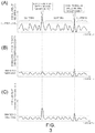
- FIG. 3 illustrates a graph of the reception data
- (B) illustrates a graph of the scan-to-scan correlation data
- (C) illustrates a graph of clutter suppressed data.
- a series of reception data read from the sweep memory 4 when the antenna angle is ⁇ 1 will be shown as the graph (A) of Fig. 3 .
- the vertical axis of the graph corresponds to the signal level of the reception data
- the horizontal axis corresponds to the read-out address (that is, corresponds to the distance r from the ship concerned to the echo source) from the sweep memory.
- the reception data is illustrated as a continuous analog waveform. However, the illustration is merely conceptual, and, in fact, the reception data read from the sweep memory 4 is discrete digital data.
- the echo from the high-speed moving target object and the echo from the low-speed moving target object appear as peaks of the signal level.
- small peaks other than the echoes from the target objects are also detected as shown in the waveform of the graph (A) of Fig. 3 , these small peaks are signals unnecessary to display a radar image, such as the clutters and noises.
- the graph (B) shows a signal obtained by carrying out the scan-to-scan correlation processing to the reception signal shown in the graph (A). As shown in this graph, when the scan-to-scan correlation processing is performed, the echo from the high-speed moving target object will be suppressed.
- a ship which can travel at a high speed in the sea where strong sea clutters are generated is a comparatively large-sized ship with a large RCS (Radar Cross-section).
- RCS Radar Cross-section
- the signal level of the echo from this kind of ship is strong compared with the clutter level.
- the clutters are strong, a large majority of target objects which moves at a high speed in this clutters can be distinguished from the clutters without performing the scan-to-scan correlation processing.
- a comparatively small ship with a small RCS can travel at a high speed.
- the level of the sea clutters is low, the echo indicative of the ship and the clutters are easily distinguishable from each other as well. That is, generally, the signal level of the echo from the ship which travels at a high speed is higher than the clutter level.
- the present invention utilizes this principle.
- the graph (C) shows a result (clutter suppressed data) obtained by processing the reception signal shown in the graph (A) by the clutter suppressing module.
- the vertical axis of the graph (C) of Fig. 3 is a signal level of the clutter suppressed data.
- the clutter suppressing module 5 of this embodiment can suppress only the signal level of the clutters, while maintaining the signal level of the data indicative of the echoes of the target objects.
- the clutter suppressing module 5 when the clutter suppressing module 5 reads the reception data from the sweep memory 4, it performs processing for suppressing the clutters to the reception data.
- the detailed configuration and operation of the clutter suppressing module 5 are described later.
- the data which is obtained by suppressing the clutters from the reception data by the clutter suppressing module (clutter suppressed data) is outputted to the binarizing module 6.
- the binarizing module 6 performs binarizing by comparing the signal level of the clutter suppressed data with a predetermined binarizing threshold. Specifically, if the signal level of the clutter suppressed data is greater than the binarizing threshold, the binarizing module 6 outputs data indicating that the "target object exists” (for example, "1"). On the other hand, if the signal level of the clutter suppressed data is less than the binarizing threshold, it output data indicating that the "target object does not exist” (for example, "0").
- a selection threshold for selecting between the reception data and the scan-to-scan correlation data by the output selection module 5 is set in order to determine whether the target object is contained in the reception data.
- the binarizing threshold is typically set less than the selection threshold because it is necessary to be used for distinguishing the existence of the target object for the scan-to-scan correlation processed data.
- the signal processing module 21 is preferred to be configured as follows.
- the signal processing module 21 obtains an unnecessary signal level of the reception data based on the reception data.
- the selection threshold is determined based on the unnecessary signal level obtained by the signal processing module.
- the selection threshold is set corresponding to an overall level variation of the unnecessary signal due to a weather condition that affects to the sea clutters, such as a rainstorm. Thereby, because the selection threshold can be determined appropriately, even if the level variation is generated due to an external factor, the target object detection and the unnecessary signal suppression can be performed appropriately.
- the signal processing module 21 is configured as follows.
- the signal processing module 21 includes a tracking module for tracking the target object based on the data outputted from the output selection module. Thereby, the target object including the high-speed moving target object can be certainly tracked.
- a configuration where the tracking module 7 is provided is illustrated.
- the processed result by the binarizing module 6 described above (binarized data) is outputted to the tracking module 7.
- the tracking module 7 tracks each target object by sequentially acquiring a position of a corresponding target object echo. The tracking is described briefly as follows.
- the tracking module 7 evaluates a continuity in a plane of the binarized data inputted from the binarizing module 6. Next, the tracking module 7 extracts spatially-collective data which is determined to be the "target object exists," and acquires coordinates of a representative point. It would appear that the spatially-collective data indicates the echo from a single target object. The coordinates of the representative point indicate the position of the target object.
- the tracking module 7 tracks by inputting the coordinates of the representative point into a tracking filter.
- a tracking filter an ⁇ - ⁇ filter, a Kalman filter or the like may be used.
- the tracking module 7 can acquire information including a position, a moving direction, a moving speed and the like of each target object.
- the clutter suppressing module 5 includes hardware having a CPU, a RAM, a ROM, and the like (not illustrated), and a signal processing program stored in the ROM.
- the signal processing program implements a signal processing method of this embodiment using the hardware which the clutter suppressing module 5 equips.
- this signal processing program includes a scan-to-scan correlation processing step, an output selection step, and a clutter level setting step.
- the clutter suppressing module 5 can function as the scan-to-scan correlation processing module 11, the output selection module 12, and threshold setting module 13, described above.
- the method is described in detail, also referring to Fig. 1 .
- the scan-to-scan correlation processing module 11 performs, as the scan-to-scan correlation processing, processing where a correlation between first reception data and second reception data acquired by the past scan before the first reception data (previously acquired reception data) is taken.
- the reception data of which the signal level varies at random with time, is suppressed in signal level by the scan-to-scan correlation processing. Thereby, a noise, a clutter and the like can be suppressed.
- the scan-to-scan correlation processing module 11 further includes a two-dimensional memory 14 for storing past scan-to-scan correlation data, and obtains scan-to-scan correlation data based on the reception data and the past scan-to-scan correlation data. Thereby, the suppressing of a noise, a clutter and the like by the scan-to-scan correlation processing can be performed more appropriately.
- the reception data from the sweep memory 4 is inputted into the scan-to-scan correlation processing module 11.
- the scan-to-scan correlation processing module 11 performs processing for suppressing the clutters contained in the reception data based on the past data and the latest reception data (scan-to-scan correlation processing).
- the function of the scan-to-scan correlation processing module 11 corresponds to the scan-to-scan correlation processing step of the signal processing program.
- the echo signal from the target object is a signal which is temporally-stably detected, and the clutter is a signal which varies at random with time.
- the term "temporally stable” as used herein means that the signal level between the scans is stable. If the echoes of a similar signal level is stably detected from a position of the antenna angle ⁇ and the distance r for two or more scans, it can be said that the signal from the position (r, ⁇ ) is stable with time.
- the signal varying at random unnecessary signal, such as the clutter
- the signal detected stably with time at the position (r, ⁇ ) echo from the target object or the like.
- recursive digital filter processing expressed by the following equation is applied to the reception data to suppress the clutters.
- Y r, ⁇ (n) is the scan-to-scan correlation data
- X r, ⁇ (n) is the latest reception data
- Y r, ⁇ (n-1) is the scan-to-scan correlation data of one scan before.
- a range of a coefficient ⁇ is (0 ⁇ 1).
- a configuration of the scan-to-scan correlation processing module 11 for implementing the scan-to-scan correlation processing described above is particularly described with reference to Fig. 4 .
- the scan-to-scan correlation processing module 11 includes the two-dimensional memory 14.
- the two-dimensional memory 14 stores the scan-to-scan correlation data of one scan before (Y r, ⁇ (n-1), described above) for one rotation of the antenna (that is, for one scan).
- the scan-to-scan correlation processing module 11 When the scan-to-scan correlation processing module 11 reads the new reception data X r, ⁇ (n) from the sweep memory 4, it reads the scan-to-scan correlation data Y r, ⁇ (n-1) (of one scan before) corresponding to the new reception data X r, ⁇ (n) from the two-dimensional memory 14. The scan-to-scan correlation processing module 11 obtains the new scan-to-scan correlation data Y r, ⁇ (n) by calculating Equation (1) described above. Finally, the scan-to-scan correlation processing module 11 updates the scan-to-scan correlation data Y r, ⁇ (n-1) of one scan before stored in the two-dimensional memory 14 with the new scan-to-scan correlation data Y r, ⁇ (n).
- the above scan-to-scan correlation processing is thus performed for the reception data shown in the graph (A) of Fig. 3 , and the result (scan-to-scan correlation data) is shown in the graph (B) of Fig. 3 .
- the clutters can be suppressed by the scan-to-scan correlation processing, while maintaining the signal level of the echo from the low-speed moving target object.
- the binarizing module 6 can detect the low-speed moving target object.
- the conventional radar device does not perform the scan-to-scan correlation processing as preprocessing of the binarizing processing. For this reason, if the echo from the target object is buried in the clutters, the echo cannot be detected by the binarizing processing. Therefore, in this conventional radar device, when the clutters are strong, an accurate tracking of the target object cannot be performed.
- the binarizing processing is performed after suppressing the clutters by the scan-to-scan correlation processing as described above. Thereby, even if the target object echo is buried in the clutters, it can be detected by the binarizing module 6. As a result, an accurate tracking can be performed by the tracking module 7.
- the clutter suppressing module 5 of the radar device 10 of this embodiment may also have a function as the output selection module 12 and the threshold setting module 13.
- the reception data from the sweep memory 4 is inputted into the threshold setting module 13. Based on the reception data, the threshold setting module 13 obtains a current clutter level (clutter intensity), and outputs it to the output selection module 12.
- the function of the threshold setting module 13 corresponds to the clutter level setting step of the signal processing program.
- the reception data from the sweep memory 4 and the scan-to-scan correlation data from the scan-to-scan correlation processing module 11 are inputted into the output selection module 12.
- the output selection module 12 selects either one of the reception data and the scan-to-scan correlation data based on the signal level of the reception data.
- the selected data is outputted as the clutter suppressed data.
- the function of the output selection module 12 corresponds to the output selection step of the signal processing program.
- the output selection module 12 determines in advance a selection threshold having a value greater than the clutter level set by the threshold setting module 13.
- the output selection module 12 compares a signal level of the reception data with the selection threshold.
- the output selection module 12 outputs the reception data from the sweep memory 4 (reception data which is not scan-to-scan correlation processed) to the binarizing module 6 as it is.
- the scan-to-scan correlation data which is scan-to-scan correlation processed, is necessary to the detect target object by the binarizing module.
- the output selection module 12 outputs the scan-to-scan correlation data to the binarizing module 6.
- the data outputted from the clutter suppressing module 5 (clutter suppressed data) configured as described above will be as shown in the graph (C) of Fig. 3 , for example.
- the scan-to-scan correlation processing module 11 scan-to-scan correlation data
- data where the reception data having the signal level greater than the selection threshold (data which is not scan-to-scan correlation processed) is embedded is outputted from the clutter suppressing module 5.
- the signal level of the echo from the ship which moves at a high speed is generally greater than the clutter level. Therefore, for a great portion of the high-speed moving target objects, the reception data where the signal level is not suppressed (reception data which is not scan-to-scan correlation processed) can be outputted from the clutter suppressing module 5.
- the signal from which only the clutters are suppressed can be obtained with neither of the echo from the high-speed moving target object or the echo from the low-speed moving target object being suppressed. Therefore, even if the target object is the high-speed moving target object, it can be appropriately determined in the latter stage of the binarizing module 6 that the "target object exists.”
- the radar device 10 of this embodiment includes the antenna 1, and the signal processing module 21 including the sweep memory 4, the scan-to-scan correlation processing module 11, and the output selection module 12. If the signal level of the reception data is greater than the predetermined selection threshold, the output selection module 12 outputs the reception data, and if the signal level of the reception data is less than the selection threshold, the output selection module 12 selectively outputs the scan-to-scan correlation data.
- the reception data which is not scan-to-scan correlation processed can be outputted.
- the echo signal level from the ship which can travel at a high speed is higher than the clutter level.
- the reception data of which the signal level is not suppressed by the scan-to-scan correlation processing can be outputted. Therefore, only the unnecessary signals can be suppressed by the scan-to-scan correlation processing, while preventing the signal level of the echo from a great portion of the high-speed moving target objects from being suppressed by the scan-to-scan correlation processing.
- the signal processing module 21 of this embodiment includes the threshold setting module 13 for obtaining the clutter level of the reception data based on the reception data.
- the selection threshold is determined based on the clutter level obtained by the threshold setting module 13. Thereby, the selection threshold can be determined appropriately. Therefore, even if the clutter level varies according to the weather condition or the like, the detection of the target object and the suppression of the clutters can be performed appropriately.
- the signal processing module 21 of this embodiment includes the tracking module 7 for tracking the target object based on the data outputted from the output selection module 12. Thereby, the target object including the high-speed moving target object can be tracked certainly.
- Fig. 5 is a block diagram of a radar device 100 according to this embodiment, illustrated as an example of the (radar) signal processing device embodying the invention.
- configurations of this embodiment the same as and similar to those of the first embodiment described above are denoted with the same numerals, and description thereof is thus omitted.
- the radar signal processing device of this embodiment includes an echo trail generation processing module for performing echo trail generation processing based on the data outputted from the output selection module. Thereby, it can leave trails to both the high-speed moving target object and the low-speed moving target object.
- a signal processing module 41 provided to the radar device 100 of this embodiment clutter suppressed data from the clutter suppressing module 5 is outputted to the image memory 31.
- the image memory 31 stores a two-dimensional raster image.
- the clutter suppressed data is plotted on a two-dimensional image, and, as a result, a raster radar image indicating a situation of target objects around the ship concerned can be generated.
- the image memory 31 is connected with a display 33 via an image processing module 32.
- the display 33 is configured as a raster-scan color display device, and can display the radar image stored in the image memory 31.
- the display indicates each pixel of the radar image as the two-dimensional image by a color corresponding to a signal level of the clutter suppressed data.
- the clutter suppressed data with a high signal level is indicated by a darker color
- the clutter suppressed data with a low signal level is indicated in a lighter color, thereby the situation of target objects around the ship concerned is displayed.
- the radar image is generated based on the clutter suppressed data, both the echo of the high-speed moving target object and the echo of the low-speed moving target object can be displayed, while suppressing the clutters being displayed on the radar image.
- the clutter suppressed data from the clutter suppressing module 5 is also inputted into an echo trail generation processing module 34.
- the echo trail generation processing module 34 generates a trail image indicative of a trail of each target object.
- the trail is generated as an image which leaves an "afterimage" at a position through which the echo passed to indicate the trail of the echo. This trail image is outputted to an image processing module 32.
- the trails can also be generated for the low-speed moving target object and the high-speed moving target object, while suppressing the clutters.
- the image processing module 32 superimposes the above-described radar image over the trail image, and outputs it to a display 33. Thereby, the radar image where the trail is indicated can be displayed on the display 33. An operator of the radar device can set the moving direction and the moving speed of the target object to some extent by checking the trail displayed in the radar image.
- the signal processing module 41 of this embodiment includes the echo trail generation processing module 34 for performing the echo trail generation processing based on the data outputted by the output selection module 12. Thereby, the trails can be left to both the high-speed moving target object and the low-speed moving target object.
- the embodiment may be applied to a radar device for other applications other than the ship radar described above. Further, it may also be applied to a scanning sonar as well as to the radar device, for example.
- the clutter suppressing modules 5 is described to include the hardware having the CPU, RAM, ROM and the like, and the software having a signal processing program stored in the ROM.
- all or part of the scan-to-scan correlation processing modules 11, the output selection modules 12, and the threshold setting module 13 may be implemented by hardware for exclusive use.
- the determination method of the selection threshold an arbitrary method can be used. For example, instead of the configuration where the selection threshold is determined based on the actual reception data as described above, a method of using a value obtained by adding a predetermined offset to a theoretical value of the unnecessary signal level as the selection threshold may be adopted.
- the binarized data is inputted into the tracking filter.
- the binarizing processing may be omitted, and a multi-value image may be inputted into the tracking filter instead.
- the scan-to-scan correlation processing may also be implemented using, for example, a FIR filter, other than the recursive digital filter described above.
- the output from the clutter suppressing module of the first embodiment is used for the tracking, and the output from the clutter suppressing module of the second embodiment is used for the indication on the display.
- the output data of the clutter suppressing module may be used for other various purposes, without limitation.
Landscapes
- Engineering & Computer Science (AREA)
- Remote Sensing (AREA)
- Radar, Positioning & Navigation (AREA)
- Physics & Mathematics (AREA)
- Computer Networks & Wireless Communication (AREA)
- General Physics & Mathematics (AREA)
- Electromagnetism (AREA)
- Radar Systems Or Details Thereof (AREA)
Claims (15)
- Dispositif de traitement de signal de détection d'objet cible (10), comprenant :un module de production de données de réception (20), dans lequel est entré un signal de réception, pour produire des données de réception représentatives d'un niveau de signal du signal de réception ;un module de traitement de corrélation par balayages successifs (11) pour réaliser un traitement de corrélation par balayages successifs entre les données de réception et des données de réception précédentes représentatives d'un niveau de réception d'un signal de réception acquis précédemment afin de produire des données de corrélation par balayages successifs, le module de traitement de corrélation par balayages successifs (11) comprenant une mémoire (14) pour stocker des données de corrélation par balayages successifs passées ;un module de sélection de production (12), dans lequel les données de réception et les données de corrélation par balayages successifs sont entrées, pour produire de manière sélective les unes ou les autres des données ; etun module de réglage de seuil (13) pour régler un seuil de sélection et le fournir au module de sélection de production (12),le module de sélection de production (12) réalisant une sélection entre les données de réception et les données de corrélation par balayages successifs sur la base du seuil de sélection ;le dispositif étant caractérisé en ce que :
les données de corrélation par balayages successifs produites par le module de traitement de corrélation par balayages successifs (11) sont entrées dans la mémoire (14) quand le module de sélection de production (12) produit les données de corrélation par balayages successifs et quand le module de sélection de production (12) produit les données de réception. - Dispositif de traitement de signal de détection d'objet cible selon la revendication 1, dans lequel le signal de réception est un signal d'écho en provenance d'un objet cible reçu par une antenne (1).
- Dispositif de traitement de signal de détection d'objet cible selon la revendication 2, dans lequel le module de traitement de corrélation par balayages successifs (11) comprend un filtre passe-bas qui transmet de manière sélective une composante à basse fréquence par rapport aux données de réception correspondant au signal d'écho en provenance de l'objet cible.
- Dispositif de traitement de signal de détection d'objet cible selon l'une quelconque des revendications précédentes, dans lequel le module de traitement de corrélation par balayages successifs comprend un filtre numérique récursif pour calculer :

- Dispositif de traitement de signal de détection d'objet cible selon l'une quelconque des revendications précédentes, dans lequel le module de traitement de corrélation par balayages successifs (11) réalise le traitement de corrélation par balayages successifs entre les données de réception et les données de corrélation par balayages successifs générées sur la base du signal de réception acquis précédemment, et produit de nouvelles données de corrélation par balayages successifs.
- Dispositif de traitement de signal de détection d'objet cible selon l'une quelconque des revendications précédentes, dans lequel le module de sélection de production (12) change le seuil de sélection sur la base du niveau de signal des données de réception.
- Dispositif de traitement de signal de détection d'objet cible selon l'une quelconque des revendications précédentes, dans lequel le module de sélection de production (12) produit les données de réception quand le niveau de signal du signal de réception est supérieur au seuil de sélection, et produit de manière sélective les nouvelles données de corrélation par balayages successifs quand le niveau de signal des données de réception est inférieur au seuil de sélection.
- Dispositif de traitement de signal de détection d'objet cible selon l'une quelconque des revendications précédentes, comprenant en outre une mémoire de balayage (4) pour stocker les données de réception.
- Dispositif de traitement de signal de détection d'objet cible selon la revendication 8, dans lequel la mémoire (14) sert à stocker les données de corrélation par balayages successifs d'un balayage précédent de manière à les associer à une direction d'azimut et à une distance, et
dans lequel le module de traitement de corrélation par balayages successifs lit les nouvelles données de réception dans la mémoire de balayage (4), lit les données de corrélation par balayages successifs associées à la direction d'azimut et à la distance des nouvelles données de réception dans la mémoire (14), et réalise le traitement de corrélation par balayages successifs entre les nouvelles données de réception et les données de corrélation par balayages successifs pour produire les nouvelles données de corrélation par balayages successifs. - Dispositif de traitement de signal de détection d'objet cible selon l'une quelconque des revendications précédentes, comprenant en outre un module de binarisation (6) pour binariser les données produites par le module de sélection de production sur la base d'un seuil de binarisation prédéterminé.
- Dispositif de traitement de signal de détection d'objet cible selon la revendication 10, dans lequel le seuil de binarisation est inférieur au seuil de sélection.
- Dispositif de traitement de signal de détection d'objet cible selon la revendication 11, dans lequel le module de binarisation (6) produit un signal représentatif de l'existence de l'objet cible quand la sortie du module de sélection de production (12) est supérieure au seuil de binarisation.
- Dispositif de traitement de signal de détection d'objet cible selon la revendication 12, le dispositif de traitement de signal de détection d'objet cible comprenant en outre un module de suivi (7) pour suivre l'objet cible sur la base de la sortie du module de binarisation (6).
- Programme d'affichage d'image radar, comprenant des instructions qui, lorsque le programme est exécuté par un ordinateur, amènent l'ordinateur à :recevoir un signal de réception pour produire des données de réception représentatives d'un niveau de signal du signal de réception ;réaliser un traitement de corrélation par balayages successifs entre les données de réception et des données de réception précédentes représentatives d'un niveau de réception d'un signal de réception acquis précédemment afin de produire des données de corrélation par balayages successifs, et stocker des données de corrélation par balayages successifs passées dans une mémoire (14) ;en réponse à une entrée des données de réception et des données de corrélation par balayages successifs, produire de manière sélective les unes ou les autres des données de réception et des données de corrélation par balayages successifs sur la base d'un seuil de sélection ; etproduire des données d'image pour afficher une image radar sur la base des données produites de manière sélective ;le programme étant caractérisé par l'étape consistant à :
amener l'ordinateur à entrer dans la mémoire (14) les données de corrélation par balayages successifs produites par le traitement de corrélation par balayages successifs quand les données de corrélation par balayages successifs sont produites et quand les données de réception sont produites. - Procédé d'affichage d'une image radar, comprenant les étapes consistant à :émettre une onde électromagnétique par une antenne et recevoir un signal d'écho ;réaliser un traitement de corrélation par balayages successifs entre des données de réception représentatives d'un niveau de signal du signal d'écho et des données de réception précédentes représentatives d'un niveau de réception du signal d'écho acquis précédemment afin de produire des données de corrélation par balayages successifs, et stocker des données de corrélation par balayages successifs passées dans une mémoire (14) ;régler un seuil de sélection ;en réponse à une entrée des données de réception et des données de corrélation par balayages successifs, produire de manière sélective les unes ou les autres des données de réception et des données de corrélation par balayages successifs sur la base du seuil de sélection ; etafficher une image radar générée, sur la base des données produites de manière sélective,le procédé étant caractérisé par l'étape consistant :
entrer dans la mémoire (14) les données de corrélation par balayages successifs produites par le traitement de corrélation par balayages successifs quand les données de corrélation par balayages successifs sont produites et quand les données de réception sont produites.
Applications Claiming Priority (1)
| Application Number | Priority Date | Filing Date | Title |
|---|---|---|---|
| JP2009251987A JP5658871B2 (ja) | 2009-11-02 | 2009-11-02 | 信号処理装置、レーダ装置、信号処理プログラム及び信号処理方法 |
Publications (3)
| Publication Number | Publication Date |
|---|---|
| EP2317334A2 EP2317334A2 (fr) | 2011-05-04 |
| EP2317334A3 EP2317334A3 (fr) | 2011-08-17 |
| EP2317334B1 true EP2317334B1 (fr) | 2019-06-05 |
Family
ID=43618672
Family Applications (1)
| Application Number | Title | Priority Date | Filing Date |
|---|---|---|---|
| EP10188510.1A Active EP2317334B1 (fr) | 2009-11-02 | 2010-10-22 | Procédé et programme pour afficher une image radar et dispositif de traitement de signal de détection d'objets cibles |
Country Status (4)
| Country | Link |
|---|---|
| US (1) | US8248296B2 (fr) |
| EP (1) | EP2317334B1 (fr) |
| JP (1) | JP5658871B2 (fr) |
| CN (2) | CN107255798B (fr) |
Families Citing this family (31)
| Publication number | Priority date | Publication date | Assignee | Title |
|---|---|---|---|---|
| JP5616200B2 (ja) * | 2010-11-18 | 2014-10-29 | 古野電気株式会社 | レーダ装置、注目物標検出方法及び注目物標検出プログラム |
| JP2012112672A (ja) * | 2010-11-19 | 2012-06-14 | Furuno Electric Co Ltd | 信号処理装置、レーダ装置、信号処理方法、および信号処理プログラム |
| JP2012112671A (ja) * | 2010-11-19 | 2012-06-14 | Furuno Electric Co Ltd | 探知装置、レーダ装置、探知方法、および探知プログラム |
| JP5731800B2 (ja) * | 2010-11-19 | 2015-06-10 | 古野電気株式会社 | 物標探知方法、物標探知プログラム、物標探知装置、およびレーダ装置 |
| US9568599B2 (en) | 2012-02-08 | 2017-02-14 | Furuno Electric Co. Ltd. | Radar signal processing device, radar apparatus, and method of processing radar signal |
| JP6031269B2 (ja) * | 2012-06-21 | 2016-11-24 | 古野電気株式会社 | ノイズ抑圧装置、ノイズ抑圧方法およびノイズ抑圧プログラム |
| CN102736078B (zh) * | 2012-07-06 | 2014-05-07 | 宁波成电泰克电子信息技术发展有限公司 | 一种数字船用雷达arpa中的信息处理方法 |
| JP6061588B2 (ja) * | 2012-09-26 | 2017-01-18 | 古野電気株式会社 | レーダ受信装置、及びこれを備えたレーダ装置 |
| JP6212252B2 (ja) * | 2012-11-02 | 2017-10-11 | 日本無線株式会社 | レーダ受信装置 |
| JP6231267B2 (ja) * | 2012-11-02 | 2017-11-15 | 日本無線株式会社 | レーダ受信装置 |
| CN103048645B (zh) * | 2013-01-24 | 2014-05-14 | 南京莱斯信息技术股份有限公司 | 雷达回波尾迹的显示系统及显示方法 |
| CN104182718B (zh) * | 2013-05-21 | 2019-02-12 | 深圳市腾讯计算机系统有限公司 | 一种人脸特征点定位方法及装置 |
| KR101892306B1 (ko) * | 2013-12-18 | 2018-08-27 | 주식회사 만도 | Fmcw 레이더 기반의 도로 환경 감지 방법 및 장치 |
| US9746549B1 (en) * | 2014-07-11 | 2017-08-29 | Altera Corporation | Constant false alarm rate circuitry in adaptive target detection of radar systems |
| JP6339893B2 (ja) * | 2014-08-29 | 2018-06-06 | 古野電気株式会社 | クラッタ抑圧装置及びそれを備えたレーダ装置 |
| JP6526532B2 (ja) * | 2015-09-18 | 2019-06-05 | 古野電気株式会社 | レーダ装置 |
| JP6762726B2 (ja) * | 2016-01-22 | 2020-09-30 | 古野電気株式会社 | レーダ装置及び物標追尾方法 |
| JP2017150991A (ja) * | 2016-02-25 | 2017-08-31 | 古野電気株式会社 | エコー映像表示装置 |
| CN107390179A (zh) * | 2017-07-17 | 2017-11-24 | 南京理工大学 | 一种基于通用计算机的软件化雷达显控终端 |
| RU2661941C1 (ru) * | 2017-12-14 | 2018-07-23 | Российская Федерация, от имени которой выступает Государственная корпорация по космической деятельности "РОСКОСМОС" | Способ построения радиолокационного изображения с помощью радиолокационной станции с синтезированной апертурой |
| CN108563144B (zh) * | 2018-03-30 | 2021-06-29 | 西安电子科技大学 | 一种弹载雷达信号处理半实物仿真测试系统 |
| JP7087767B2 (ja) * | 2018-07-20 | 2022-06-21 | 株式会社デンソー | 移動物体検出装置 |
| CN109471097B (zh) * | 2018-11-14 | 2022-04-22 | 湖南华诺星空电子技术有限公司 | 一种穿墙雷达信号优化处理方法及装置 |
| FR3089017B1 (fr) * | 2018-11-23 | 2020-12-11 | Thales Sa | Procede de detection par integration longue et systeme radar correspondant |
| CN111444777B (zh) * | 2020-03-03 | 2022-09-27 | 哈尔滨工程大学 | 一种同时标记阴影的前视声呐目标检测标记方法 |
| CN111551930B (zh) * | 2020-05-18 | 2022-03-18 | 南京众博达电子科技有限公司 | 基于分层显示的雷达图像显示方法 |
| CN112433209A (zh) * | 2020-10-26 | 2021-03-02 | 国网山西省电力公司电力科学研究院 | 基于广义似然比的探地雷达对地下目标检测方法及系统 |
| CN113311420B (zh) * | 2020-12-30 | 2023-10-31 | 西安电子科技大学 | 一种基于分簇管理的雷达目标检测与跟踪方法及其装置 |
| CN112284429B (zh) * | 2020-12-31 | 2021-03-26 | 深圳煜炜光学科技有限公司 | 一种激光雷达码盘均匀度校正的方法和装置 |
| CN114415142B (zh) * | 2022-01-28 | 2022-08-16 | 北京海兰信数据科技股份有限公司 | 一种基于导航雷达的雨杂波识别方法及系统 |
| KR102684561B1 (ko) * | 2023-11-10 | 2024-07-12 | 삼영이엔씨 (주) | 알파 레이더 시스템 |
Family Cites Families (17)
| Publication number | Priority date | Publication date | Assignee | Title |
|---|---|---|---|---|
| US4005415A (en) * | 1975-03-31 | 1977-01-25 | The United States Of America As Represented By The Secretary Of The Navy | Automated radar data processing system |
| DE3924859C2 (de) * | 1989-07-27 | 1998-06-04 | Daimler Benz Aerospace Ag | Verfahren zur Unterdrückung von Seeclutter-Echos |
| US5097268A (en) * | 1991-01-08 | 1992-03-17 | Raytheon Company | Radar apparatus and method for enhancing the display of moving targets |
| JPH08136641A (ja) | 1994-11-14 | 1996-05-31 | Furuno Electric Co Ltd | レーダ装置 |
| ATE237811T1 (de) * | 1996-05-14 | 2003-05-15 | Honeywell Int Inc | Autonomes landeführungssystem |
| JPH1144753A (ja) * | 1997-07-25 | 1999-02-16 | Japan Radio Co Ltd | 移動目標追尾方法及びレーダビデオ処理装置 |
| DE10034080C2 (de) * | 2000-07-13 | 2003-05-15 | Eads Deutschland Gmbh | Umlauf-Integration-Korrelation |
| JP3680265B2 (ja) * | 2000-08-24 | 2005-08-10 | 日本無線株式会社 | レーダ装置 |
| JP4412569B2 (ja) | 2000-11-02 | 2010-02-10 | 日本無線株式会社 | レーダ表示装置 |
| JP2002243842A (ja) * | 2001-02-21 | 2002-08-28 | Furuno Electric Co Ltd | 探知装置 |
| JP2003315439A (ja) | 2002-04-19 | 2003-11-06 | Furuno Electric Co Ltd | 舶用レーダ装置 |
| JP4164406B2 (ja) * | 2003-06-02 | 2008-10-15 | 古野電気株式会社 | レーダ装置および類似装置 |
| JP2008070217A (ja) * | 2006-09-13 | 2008-03-27 | Furuno Electric Co Ltd | レーダ装置 |
| US7735349B2 (en) * | 2007-01-31 | 2010-06-15 | Biosense Websters, Inc. | Correlation of ultrasound images and gated position measurements |
| US20080269611A1 (en) * | 2007-04-24 | 2008-10-30 | Gianni Pedrizzetti | Flow characteristic imaging in medical diagnostic ultrasound |
| JP5180543B2 (ja) * | 2007-08-31 | 2013-04-10 | 古野電気株式会社 | レーダ装置または該レーダ装置に類似する装置 |
| JP5309664B2 (ja) | 2008-04-08 | 2013-10-09 | 富士ゼロックス株式会社 | 文書管理装置及びプログラム |
-
2009
- 2009-11-02 JP JP2009251987A patent/JP5658871B2/ja active Active
-
2010
- 2010-10-22 EP EP10188510.1A patent/EP2317334B1/fr active Active
- 2010-11-01 US US12/916,737 patent/US8248296B2/en active Active
- 2010-11-02 CN CN201710421263.3A patent/CN107255798B/zh active Active
- 2010-11-02 CN CN2010105343372A patent/CN102053241A/zh active Pending
Non-Patent Citations (1)
| Title |
|---|
| None * |
Also Published As
| Publication number | Publication date |
|---|---|
| EP2317334A2 (fr) | 2011-05-04 |
| CN102053241A (zh) | 2011-05-11 |
| CN107255798B (zh) | 2021-01-26 |
| CN107255798A (zh) | 2017-10-17 |
| EP2317334A3 (fr) | 2011-08-17 |
| US8248296B2 (en) | 2012-08-21 |
| US20110102248A1 (en) | 2011-05-05 |
| JP5658871B2 (ja) | 2015-01-28 |
| JP2011095215A (ja) | 2011-05-12 |
Similar Documents
| Publication | Publication Date | Title |
|---|---|---|
| EP2317334B1 (fr) | Procédé et programme pour afficher une image radar et dispositif de traitement de signal de détection d'objets cibles | |
| US8830117B2 (en) | Method, device and program for setting threshold, and method, device and program for detecting target object | |
| US8264395B2 (en) | Radar device and rain/snow area detecting device | |
| US8593335B2 (en) | Method and device for processing echo signal, radar device and echo signal processing program | |
| EP2455777B1 (fr) | Appareil de radar et procédé de détection d'objet cible | |
| US8405544B2 (en) | Method and device for processing signal, radar apparatus, and program for processing signal | |
| US20100321231A1 (en) | Radar device | |
| CN111133333B (zh) | 雷达装置以及目标追踪方法 | |
| JP2008164545A (ja) | 移動目標検出装置、移動目標検出方法および移動目標検出プログラム | |
| JP5130844B2 (ja) | クラッタ判別方法およびレーダ装置 | |
| JP5398195B2 (ja) | レーダ装置 | |
| JP6250404B2 (ja) | レーダ信号処理装置、レーダ装置、及びレーダ信号処理方法 | |
| CN107110967B (zh) | 追踪处理装置及追踪处理方法 | |
| JP6192151B2 (ja) | 信号選別装置、信号選別方法、及びレーダ装置。 | |
| US8665140B2 (en) | Method and device for processing signal, and radar device | |
| JP5520035B2 (ja) | 信号処理装置、レーダ装置及び信号処理プログラム | |
| KR101339108B1 (ko) | 레이더 시스템의 표적 탐지방법 | |
| JP2011242253A (ja) | エコー信号処理装置、レーダ装置、エコー信号処理プログラム及びエコー信号処理方法 | |
| JP2010286404A (ja) | 移動目標検出装置 | |
| WO2005043187A1 (fr) | Systeme et procede de suppression de clutter de mer dans une image radar | |
| JP2011191141A (ja) | 偽像低減装置、レーダ装置、偽像低減方法、および偽像低減プログラム | |
| JP2001141817A (ja) | レーダ装置 | |
| KR20150109969A (ko) | 선박용 레이더의 근거리 해면반사 제거 장치 | |
| CN118409280A (zh) | 距离折叠回波抑制方法、相控阵雷达、存储介质及产品 |
Legal Events
| Date | Code | Title | Description |
|---|---|---|---|
| PUAI | Public reference made under article 153(3) epc to a published international application that has entered the european phase |
Free format text: ORIGINAL CODE: 0009012 |
|
| AK | Designated contracting states |
Kind code of ref document: A2 Designated state(s): AL AT BE BG CH CY CZ DE DK EE ES FI FR GB GR HR HU IE IS IT LI LT LU LV MC MK MT NL NO PL PT RO RS SE SI SK SM TR |
|
| AX | Request for extension of the european patent |
Extension state: BA ME |
|
| PUAL | Search report despatched |
Free format text: ORIGINAL CODE: 0009013 |
|
| AK | Designated contracting states |
Kind code of ref document: A3 Designated state(s): AL AT BE BG CH CY CZ DE DK EE ES FI FR GB GR HR HU IE IS IT LI LT LU LV MC MK MT NL NO PL PT RO RS SE SI SK SM TR |
|
| AX | Request for extension of the european patent |
Extension state: BA ME |
|
| RIC1 | Information provided on ipc code assigned before grant |
Ipc: G01S 13/72 20060101ALI20110711BHEP Ipc: G01S 13/524 20060101ALI20110711BHEP Ipc: G01S 13/89 20060101ALI20110711BHEP Ipc: G01S 7/292 20060101AFI20110711BHEP |
|
| 17P | Request for examination filed |
Effective date: 20111111 |
|
| 17Q | First examination report despatched |
Effective date: 20151023 |
|
| STAA | Information on the status of an ep patent application or granted ep patent |
Free format text: STATUS: EXAMINATION IS IN PROGRESS |
|
| GRAP | Despatch of communication of intention to grant a patent |
Free format text: ORIGINAL CODE: EPIDOSNIGR1 |
|
| STAA | Information on the status of an ep patent application or granted ep patent |
Free format text: STATUS: GRANT OF PATENT IS INTENDED |
|
| INTG | Intention to grant announced |
Effective date: 20181128 |
|
| GRAS | Grant fee paid |
Free format text: ORIGINAL CODE: EPIDOSNIGR3 |
|
| GRAJ | Information related to disapproval of communication of intention to grant by the applicant or resumption of examination proceedings by the epo deleted |
Free format text: ORIGINAL CODE: EPIDOSDIGR1 |
|
| GRAL | Information related to payment of fee for publishing/printing deleted |
Free format text: ORIGINAL CODE: EPIDOSDIGR3 |
|
| STAA | Information on the status of an ep patent application or granted ep patent |
Free format text: STATUS: EXAMINATION IS IN PROGRESS |
|
| GRAR | Information related to intention to grant a patent recorded |
Free format text: ORIGINAL CODE: EPIDOSNIGR71 |
|
| STAA | Information on the status of an ep patent application or granted ep patent |
Free format text: STATUS: GRANT OF PATENT IS INTENDED |
|
| INTC | Intention to grant announced (deleted) | ||
| GRAA | (expected) grant |
Free format text: ORIGINAL CODE: 0009210 |
|
| STAA | Information on the status of an ep patent application or granted ep patent |
Free format text: STATUS: THE PATENT HAS BEEN GRANTED |
|
| AK | Designated contracting states |
Kind code of ref document: B1 Designated state(s): AL AT BE BG CH CY CZ DE DK EE ES FI FR GB GR HR HU IE IS IT LI LT LU LV MC MK MT NL NO PL PT RO RS SE SI SK SM TR |
|
| INTG | Intention to grant announced |
Effective date: 20190426 |
|
| REG | Reference to a national code |
Ref country code: GB Ref legal event code: FG4D |
|
| REG | Reference to a national code |
Ref country code: CH Ref legal event code: EP |
|
| REG | Reference to a national code |
Ref country code: AT Ref legal event code: REF Ref document number: 1140561 Country of ref document: AT Kind code of ref document: T Effective date: 20190615 |
|
| REG | Reference to a national code |
Ref country code: DE Ref legal event code: R096 Ref document number: 602010059235 Country of ref document: DE |
|
| REG | Reference to a national code |
Ref country code: IE Ref legal event code: FG4D |
|
| REG | Reference to a national code |
Ref country code: NL Ref legal event code: MP Effective date: 20190605 |
|
| REG | Reference to a national code |
Ref country code: LT Ref legal event code: MG4D |
|
| PG25 | Lapsed in a contracting state [announced via postgrant information from national office to epo] |
Ref country code: AL Free format text: LAPSE BECAUSE OF FAILURE TO SUBMIT A TRANSLATION OF THE DESCRIPTION OR TO PAY THE FEE WITHIN THE PRESCRIBED TIME-LIMIT Effective date: 20190605 Ref country code: ES Free format text: LAPSE BECAUSE OF FAILURE TO SUBMIT A TRANSLATION OF THE DESCRIPTION OR TO PAY THE FEE WITHIN THE PRESCRIBED TIME-LIMIT Effective date: 20190605 Ref country code: LT Free format text: LAPSE BECAUSE OF FAILURE TO SUBMIT A TRANSLATION OF THE DESCRIPTION OR TO PAY THE FEE WITHIN THE PRESCRIBED TIME-LIMIT Effective date: 20190605 Ref country code: NO Free format text: LAPSE BECAUSE OF FAILURE TO SUBMIT A TRANSLATION OF THE DESCRIPTION OR TO PAY THE FEE WITHIN THE PRESCRIBED TIME-LIMIT Effective date: 20190905 Ref country code: HR Free format text: LAPSE BECAUSE OF FAILURE TO SUBMIT A TRANSLATION OF THE DESCRIPTION OR TO PAY THE FEE WITHIN THE PRESCRIBED TIME-LIMIT Effective date: 20190605 Ref country code: SE Free format text: LAPSE BECAUSE OF FAILURE TO SUBMIT A TRANSLATION OF THE DESCRIPTION OR TO PAY THE FEE WITHIN THE PRESCRIBED TIME-LIMIT Effective date: 20190605 Ref country code: FI Free format text: LAPSE BECAUSE OF FAILURE TO SUBMIT A TRANSLATION OF THE DESCRIPTION OR TO PAY THE FEE WITHIN THE PRESCRIBED TIME-LIMIT Effective date: 20190605 |
|
| PG25 | Lapsed in a contracting state [announced via postgrant information from national office to epo] |
Ref country code: RS Free format text: LAPSE BECAUSE OF FAILURE TO SUBMIT A TRANSLATION OF THE DESCRIPTION OR TO PAY THE FEE WITHIN THE PRESCRIBED TIME-LIMIT Effective date: 20190605 Ref country code: LV Free format text: LAPSE BECAUSE OF FAILURE TO SUBMIT A TRANSLATION OF THE DESCRIPTION OR TO PAY THE FEE WITHIN THE PRESCRIBED TIME-LIMIT Effective date: 20190605 Ref country code: GR Free format text: LAPSE BECAUSE OF FAILURE TO SUBMIT A TRANSLATION OF THE DESCRIPTION OR TO PAY THE FEE WITHIN THE PRESCRIBED TIME-LIMIT Effective date: 20190906 Ref country code: BG Free format text: LAPSE BECAUSE OF FAILURE TO SUBMIT A TRANSLATION OF THE DESCRIPTION OR TO PAY THE FEE WITHIN THE PRESCRIBED TIME-LIMIT Effective date: 20190905 |
|
| REG | Reference to a national code |
Ref country code: AT Ref legal event code: MK05 Ref document number: 1140561 Country of ref document: AT Kind code of ref document: T Effective date: 20190605 |
|
| PG25 | Lapsed in a contracting state [announced via postgrant information from national office to epo] |
Ref country code: PT Free format text: LAPSE BECAUSE OF FAILURE TO SUBMIT A TRANSLATION OF THE DESCRIPTION OR TO PAY THE FEE WITHIN THE PRESCRIBED TIME-LIMIT Effective date: 20191007 Ref country code: NL Free format text: LAPSE BECAUSE OF FAILURE TO SUBMIT A TRANSLATION OF THE DESCRIPTION OR TO PAY THE FEE WITHIN THE PRESCRIBED TIME-LIMIT Effective date: 20190605 Ref country code: CZ Free format text: LAPSE BECAUSE OF FAILURE TO SUBMIT A TRANSLATION OF THE DESCRIPTION OR TO PAY THE FEE WITHIN THE PRESCRIBED TIME-LIMIT Effective date: 20190605 Ref country code: SK Free format text: LAPSE BECAUSE OF FAILURE TO SUBMIT A TRANSLATION OF THE DESCRIPTION OR TO PAY THE FEE WITHIN THE PRESCRIBED TIME-LIMIT Effective date: 20190605 Ref country code: RO Free format text: LAPSE BECAUSE OF FAILURE TO SUBMIT A TRANSLATION OF THE DESCRIPTION OR TO PAY THE FEE WITHIN THE PRESCRIBED TIME-LIMIT Effective date: 20190605 Ref country code: AT Free format text: LAPSE BECAUSE OF FAILURE TO SUBMIT A TRANSLATION OF THE DESCRIPTION OR TO PAY THE FEE WITHIN THE PRESCRIBED TIME-LIMIT Effective date: 20190605 Ref country code: EE Free format text: LAPSE BECAUSE OF FAILURE TO SUBMIT A TRANSLATION OF THE DESCRIPTION OR TO PAY THE FEE WITHIN THE PRESCRIBED TIME-LIMIT Effective date: 20190605 |
|
| PG25 | Lapsed in a contracting state [announced via postgrant information from national office to epo] |
Ref country code: SM Free format text: LAPSE BECAUSE OF FAILURE TO SUBMIT A TRANSLATION OF THE DESCRIPTION OR TO PAY THE FEE WITHIN THE PRESCRIBED TIME-LIMIT Effective date: 20190605 Ref country code: IT Free format text: LAPSE BECAUSE OF FAILURE TO SUBMIT A TRANSLATION OF THE DESCRIPTION OR TO PAY THE FEE WITHIN THE PRESCRIBED TIME-LIMIT Effective date: 20190605 Ref country code: IS Free format text: LAPSE BECAUSE OF FAILURE TO SUBMIT A TRANSLATION OF THE DESCRIPTION OR TO PAY THE FEE WITHIN THE PRESCRIBED TIME-LIMIT Effective date: 20191005 |
|
| REG | Reference to a national code |
Ref country code: DE Ref legal event code: R097 Ref document number: 602010059235 Country of ref document: DE |
|
| PG25 | Lapsed in a contracting state [announced via postgrant information from national office to epo] |
Ref country code: TR Free format text: LAPSE BECAUSE OF FAILURE TO SUBMIT A TRANSLATION OF THE DESCRIPTION OR TO PAY THE FEE WITHIN THE PRESCRIBED TIME-LIMIT Effective date: 20190605 |
|
| PLBE | No opposition filed within time limit |
Free format text: ORIGINAL CODE: 0009261 |
|
| STAA | Information on the status of an ep patent application or granted ep patent |
Free format text: STATUS: NO OPPOSITION FILED WITHIN TIME LIMIT |
|
| PG25 | Lapsed in a contracting state [announced via postgrant information from national office to epo] |
Ref country code: PL Free format text: LAPSE BECAUSE OF FAILURE TO SUBMIT A TRANSLATION OF THE DESCRIPTION OR TO PAY THE FEE WITHIN THE PRESCRIBED TIME-LIMIT Effective date: 20190605 Ref country code: DK Free format text: LAPSE BECAUSE OF FAILURE TO SUBMIT A TRANSLATION OF THE DESCRIPTION OR TO PAY THE FEE WITHIN THE PRESCRIBED TIME-LIMIT Effective date: 20190605 |
|
| 26N | No opposition filed |
Effective date: 20200306 |
|
| PG25 | Lapsed in a contracting state [announced via postgrant information from national office to epo] |
Ref country code: MC Free format text: LAPSE BECAUSE OF FAILURE TO SUBMIT A TRANSLATION OF THE DESCRIPTION OR TO PAY THE FEE WITHIN THE PRESCRIBED TIME-LIMIT Effective date: 20190605 Ref country code: SI Free format text: LAPSE BECAUSE OF FAILURE TO SUBMIT A TRANSLATION OF THE DESCRIPTION OR TO PAY THE FEE WITHIN THE PRESCRIBED TIME-LIMIT Effective date: 20190605 |
|
| REG | Reference to a national code |
Ref country code: CH Ref legal event code: PL |
|
| PG25 | Lapsed in a contracting state [announced via postgrant information from national office to epo] |
Ref country code: LU Free format text: LAPSE BECAUSE OF NON-PAYMENT OF DUE FEES Effective date: 20191022 Ref country code: CH Free format text: LAPSE BECAUSE OF NON-PAYMENT OF DUE FEES Effective date: 20191031 Ref country code: LI Free format text: LAPSE BECAUSE OF NON-PAYMENT OF DUE FEES Effective date: 20191031 |
|
| REG | Reference to a national code |
Ref country code: BE Ref legal event code: MM Effective date: 20191031 |
|
| PG25 | Lapsed in a contracting state [announced via postgrant information from national office to epo] |
Ref country code: BE Free format text: LAPSE BECAUSE OF NON-PAYMENT OF DUE FEES Effective date: 20191031 |
|
| PG25 | Lapsed in a contracting state [announced via postgrant information from national office to epo] |
Ref country code: IE Free format text: LAPSE BECAUSE OF NON-PAYMENT OF DUE FEES Effective date: 20191022 Ref country code: FR Free format text: LAPSE BECAUSE OF NON-PAYMENT OF DUE FEES Effective date: 20191031 |
|
| PG25 | Lapsed in a contracting state [announced via postgrant information from national office to epo] |
Ref country code: CY Free format text: LAPSE BECAUSE OF FAILURE TO SUBMIT A TRANSLATION OF THE DESCRIPTION OR TO PAY THE FEE WITHIN THE PRESCRIBED TIME-LIMIT Effective date: 20190605 |
|
| PG25 | Lapsed in a contracting state [announced via postgrant information from national office to epo] |
Ref country code: MT Free format text: LAPSE BECAUSE OF FAILURE TO SUBMIT A TRANSLATION OF THE DESCRIPTION OR TO PAY THE FEE WITHIN THE PRESCRIBED TIME-LIMIT Effective date: 20190605 Ref country code: HU Free format text: LAPSE BECAUSE OF FAILURE TO SUBMIT A TRANSLATION OF THE DESCRIPTION OR TO PAY THE FEE WITHIN THE PRESCRIBED TIME-LIMIT; INVALID AB INITIO Effective date: 20101022 |
|
| PG25 | Lapsed in a contracting state [announced via postgrant information from national office to epo] |
Ref country code: MK Free format text: LAPSE BECAUSE OF FAILURE TO SUBMIT A TRANSLATION OF THE DESCRIPTION OR TO PAY THE FEE WITHIN THE PRESCRIBED TIME-LIMIT Effective date: 20190605 |
|
| P01 | Opt-out of the competence of the unified patent court (upc) registered |
Effective date: 20230523 |
|
| PGFP | Annual fee paid to national office [announced via postgrant information from national office to epo] |
Ref country code: GB Payment date: 20230831 Year of fee payment: 14 |
|
| PGFP | Annual fee paid to national office [announced via postgrant information from national office to epo] |
Ref country code: DE Payment date: 20230830 Year of fee payment: 14 |