EP2305068A1 - Ausstossvorrichtung für ein bewegbares Möbelteil - Google Patents
Ausstossvorrichtung für ein bewegbares Möbelteil Download PDFInfo
- Publication number
- EP2305068A1 EP2305068A1 EP10013680A EP10013680A EP2305068A1 EP 2305068 A1 EP2305068 A1 EP 2305068A1 EP 10013680 A EP10013680 A EP 10013680A EP 10013680 A EP10013680 A EP 10013680A EP 2305068 A1 EP2305068 A1 EP 2305068A1
- Authority
- EP
- European Patent Office
- Prior art keywords
- lever
- furniture
- potentiometer
- furniture part
- measuring device
- Prior art date
- Legal status (The legal status is an assumption and is not a legal conclusion. Google has not performed a legal analysis and makes no representation as to the accuracy of the status listed.)
- Granted
Links
Images









Classifications
-
- F—MECHANICAL ENGINEERING; LIGHTING; HEATING; WEAPONS; BLASTING
- F16—ENGINEERING ELEMENTS AND UNITS; GENERAL MEASURES FOR PRODUCING AND MAINTAINING EFFECTIVE FUNCTIONING OF MACHINES OR INSTALLATIONS; THERMAL INSULATION IN GENERAL
- F16H—GEARING
- F16H21/00—Gearings comprising primarily only links or levers, with or without slides
- F16H21/10—Gearings comprising primarily only links or levers, with or without slides all movement being in, or parallel to, a single plane
- F16H21/40—Gearings comprising primarily only links or levers, with or without slides all movement being in, or parallel to, a single plane for interconverting rotary motion and oscillating motion
-
- A—HUMAN NECESSITIES
- A47—FURNITURE; DOMESTIC ARTICLES OR APPLIANCES; COFFEE MILLS; SPICE MILLS; SUCTION CLEANERS IN GENERAL
- A47B—TABLES; DESKS; OFFICE FURNITURE; CABINETS; DRAWERS; GENERAL DETAILS OF FURNITURE
- A47B88/00—Drawers for tables, cabinets or like furniture; Guides for drawers
- A47B88/40—Sliding drawers; Slides or guides therefor
- A47B88/453—Actuated drawers
- A47B88/457—Actuated drawers operated by electrically-powered actuation means
-
- A—HUMAN NECESSITIES
- A47—FURNITURE; DOMESTIC ARTICLES OR APPLIANCES; COFFEE MILLS; SPICE MILLS; SUCTION CLEANERS IN GENERAL
- A47B—TABLES; DESKS; OFFICE FURNITURE; CABINETS; DRAWERS; GENERAL DETAILS OF FURNITURE
- A47B88/00—Drawers for tables, cabinets or like furniture; Guides for drawers
- A47B88/40—Sliding drawers; Slides or guides therefor
- A47B88/453—Actuated drawers
- A47B88/46—Actuated drawers operated by mechanically-stored energy, e.g. by springs
- A47B88/463—Actuated drawers operated by mechanically-stored energy, e.g. by springs self-opening
-
- E—FIXED CONSTRUCTIONS
- E05—LOCKS; KEYS; WINDOW OR DOOR FITTINGS; SAFES
- E05F—DEVICES FOR MOVING WINGS INTO OPEN OR CLOSED POSITION; CHECKS FOR WINGS; WING FITTINGS NOT OTHERWISE PROVIDED FOR, CONCERNED WITH THE FUNCTIONING OF THE WING
- E05F15/00—Power-operated mechanisms for wings
- E05F15/60—Power-operated mechanisms for wings using electrical actuators
- E05F15/603—Power-operated mechanisms for wings using electrical actuators using rotary electromotors
- E05F15/632—Power-operated mechanisms for wings using electrical actuators using rotary electromotors for horizontally-sliding wings
- E05F15/649—Power-operated mechanisms for wings using electrical actuators using rotary electromotors for horizontally-sliding wings operated by swinging arms
-
- E—FIXED CONSTRUCTIONS
- E05—LOCKS; KEYS; WINDOW OR DOOR FITTINGS; SAFES
- E05Y—INDEXING SCHEME ASSOCIATED WITH SUBCLASSES E05D AND E05F, RELATING TO CONSTRUCTION ELEMENTS, ELECTRIC CONTROL, POWER SUPPLY, POWER SIGNAL OR TRANSMISSION, USER INTERFACES, MOUNTING OR COUPLING, DETAILS, ACCESSORIES, AUXILIARY OPERATIONS NOT OTHERWISE PROVIDED FOR, APPLICATION THEREOF
- E05Y2201/00—Constructional elements; Accessories therefor
- E05Y2201/20—Brakes; Disengaging means; Holders; Stops; Valves; Accessories therefor
- E05Y2201/214—Disengaging means
- E05Y2201/216—Clutches
-
- E—FIXED CONSTRUCTIONS
- E05—LOCKS; KEYS; WINDOW OR DOOR FITTINGS; SAFES
- E05Y—INDEXING SCHEME ASSOCIATED WITH SUBCLASSES E05D AND E05F, RELATING TO CONSTRUCTION ELEMENTS, ELECTRIC CONTROL, POWER SUPPLY, POWER SIGNAL OR TRANSMISSION, USER INTERFACES, MOUNTING OR COUPLING, DETAILS, ACCESSORIES, AUXILIARY OPERATIONS NOT OTHERWISE PROVIDED FOR, APPLICATION THEREOF
- E05Y2201/00—Constructional elements; Accessories therefor
- E05Y2201/20—Brakes; Disengaging means; Holders; Stops; Valves; Accessories therefor
- E05Y2201/23—Actuation thereof
- E05Y2201/232—Actuation thereof by automatically acting means
- E05Y2201/236—Actuation thereof by automatically acting means using force or torque
-
- E—FIXED CONSTRUCTIONS
- E05—LOCKS; KEYS; WINDOW OR DOOR FITTINGS; SAFES
- E05Y—INDEXING SCHEME ASSOCIATED WITH SUBCLASSES E05D AND E05F, RELATING TO CONSTRUCTION ELEMENTS, ELECTRIC CONTROL, POWER SUPPLY, POWER SIGNAL OR TRANSMISSION, USER INTERFACES, MOUNTING OR COUPLING, DETAILS, ACCESSORIES, AUXILIARY OPERATIONS NOT OTHERWISE PROVIDED FOR, APPLICATION THEREOF
- E05Y2201/00—Constructional elements; Accessories therefor
- E05Y2201/40—Motors; Magnets; Springs; Weights; Accessories therefor
- E05Y2201/404—Function thereof
- E05Y2201/422—Function thereof for opening
- E05Y2201/426—Function thereof for opening for the initial opening movement
-
- E—FIXED CONSTRUCTIONS
- E05—LOCKS; KEYS; WINDOW OR DOOR FITTINGS; SAFES
- E05Y—INDEXING SCHEME ASSOCIATED WITH SUBCLASSES E05D AND E05F, RELATING TO CONSTRUCTION ELEMENTS, ELECTRIC CONTROL, POWER SUPPLY, POWER SIGNAL OR TRANSMISSION, USER INTERFACES, MOUNTING OR COUPLING, DETAILS, ACCESSORIES, AUXILIARY OPERATIONS NOT OTHERWISE PROVIDED FOR, APPLICATION THEREOF
- E05Y2201/00—Constructional elements; Accessories therefor
- E05Y2201/40—Motors; Magnets; Springs; Weights; Accessories therefor
- E05Y2201/43—Motors
- E05Y2201/434—Electromotors; Details thereof
-
- E—FIXED CONSTRUCTIONS
- E05—LOCKS; KEYS; WINDOW OR DOOR FITTINGS; SAFES
- E05Y—INDEXING SCHEME ASSOCIATED WITH SUBCLASSES E05D AND E05F, RELATING TO CONSTRUCTION ELEMENTS, ELECTRIC CONTROL, POWER SUPPLY, POWER SIGNAL OR TRANSMISSION, USER INTERFACES, MOUNTING OR COUPLING, DETAILS, ACCESSORIES, AUXILIARY OPERATIONS NOT OTHERWISE PROVIDED FOR, APPLICATION THEREOF
- E05Y2900/00—Application of doors, windows, wings or fittings thereof
- E05Y2900/20—Application of doors, windows, wings or fittings thereof for furniture, e.g. cabinets
-
- Y—GENERAL TAGGING OF NEW TECHNOLOGICAL DEVELOPMENTS; GENERAL TAGGING OF CROSS-SECTIONAL TECHNOLOGIES SPANNING OVER SEVERAL SECTIONS OF THE IPC; TECHNICAL SUBJECTS COVERED BY FORMER USPC CROSS-REFERENCE ART COLLECTIONS [XRACs] AND DIGESTS
- Y10—TECHNICAL SUBJECTS COVERED BY FORMER USPC
- Y10T—TECHNICAL SUBJECTS COVERED BY FORMER US CLASSIFICATION
- Y10T74/00—Machine element or mechanism
- Y10T74/18—Mechanical movements
- Y10T74/18568—Reciprocating or oscillating to or from alternating rotary
-
- Y—GENERAL TAGGING OF NEW TECHNOLOGICAL DEVELOPMENTS; GENERAL TAGGING OF CROSS-SECTIONAL TECHNOLOGIES SPANNING OVER SEVERAL SECTIONS OF THE IPC; TECHNICAL SUBJECTS COVERED BY FORMER USPC CROSS-REFERENCE ART COLLECTIONS [XRACs] AND DIGESTS
- Y10—TECHNICAL SUBJECTS COVERED BY FORMER USPC
- Y10T—TECHNICAL SUBJECTS COVERED BY FORMER US CLASSIFICATION
- Y10T74/00—Machine element or mechanism
- Y10T74/19—Gearing
- Y10T74/19642—Directly cooperating gears
- Y10T74/19679—Spur
- Y10T74/19684—Motor and gearing
Definitions
- the present invention relates, in a first variant, to an ejection device for a furniture part movably mounted in or on a furniture body, with a pivotably mounted lever, wherein a first roller is arranged at the free end of the lever.
- the prioritized senior WO 2004/100718 A1 has an ejection device for a movably mounted in or on a furniture body furniture part (door or drawer) to the object with a pivotally mounted lever, with an electric drive unit and a control or regulating device for controlling or regulating the drive unit.
- the object of the invention is to provide an ejection device which does not have this problem.
- the inventive measure uniform loading of the drive lever driving the drive unit is achieved over the entire discharge path.
- the pivotally mounted lever comes first with the spaced from the free end of the lever arranged second roller with the movable Mööffeil in contact, whereby the force exerted on the movable furniture part torque is smaller than in immediate contact with the roller arranged at the free end of the lever.
- the drive unit which may include an electric motor, loaded during the initial acceleration of the movable furniture part with a lower torque. This results in a more favorable starting behavior. The user perceives this as a sweeping initial acceleration of the movable furniture part.
- the second roller is arranged at a distance of approximately half the lever length from the free end of the lever on the lever. This results in a satisfactory in practice distribution of the load forces acting on the drive unit.
- a further, second variant of the invention relates to an ejection device for a movably mounted in or on a furniture body furniture part, in particular according to claim 1 or 2, with a pivotally mounted lever and a particular electric drive unit for driving the lever.
- Object of this variant of the invention is to provide a generic ejection device, which is characterized by a lower noise.
- the lever has at least a first lever part and a second lever part, wherein the first lever part is contactable with the movable furniture part and the second lever part is driven by the drive unit and that the first lever part with the second lever part limited movable coupled is, wherein the first lever part is biased with respect to the second lever part by a force accumulator,
- the two-part design of the lever results in a clearance between the first and the second lever part.
- the bias of the first Habelteils with respect to the second lever part of the first lever part is pressed against the movable furniture part. Due to the reaction force, the second lever part is pushed away from the first lever part, as a result of which the parts of the drive unit which are in contact with the second lever part are also put under tension. Surprisingly, it has been found that this leads to a reduction of the operating noise of the ejection device.
- the first lever part is biased by a spring with respect to the second lever part.
- a further, third variant of the invention relates to an ejection device for a movably mounted in or on a furniture body furniture part, in particular according to one of claims 1 to 4, with a pivotally mounted lever for ejecting the movable furniture part, a particular electric drive unit for driving off the lever and a control device for controlling the drive unit.
- Object of this variant of the invention is therefore to provide a discharge device, which is characterized by an intuitive releasability.
- a switch for triggering the ejection device is arranged on or in the lever, wherein the signals of the switch at least the control or regulating device can be fed.
- the inventive measure allows the triggering of the ejection device by pressing the front panel of the movable furniture part in the furniture body inside. This is of course in the closed end position of the movable furniture part 5 enough game to let. As soon as the movable furniture part contacts the switch arranged on the lever, the switch sends the triggering signal to the control device of the ejection device.
- lever has at least one first and one second lever part
- switch has at least two contacts, wherein the first contact is arranged on the first lever part and the second contact is arranged on the second lever part.
- the first lever part lying against the movable furniture part is pressed in the direction of the second lever part, whereby the two contacts touch and close the circuit.
- an energy storage device is arranged between the two lever parts for generating a bias voltage.
- the switch comprises a pressure switch, which is preferably arranged at the free end of the lever.
- a two-part design of the lever can be omitted in this embodiment.
- a further fourth variant of the invention relates to an ejection device for a movably mounted in or on a furniture body furniture part, in particular according to one of claims 1 to 8, with an ejector for ejecting the movable Gurbefteils, a particular electric drive unit, a transmission for transmitting power from the Drive unit to the ejector and a control device for controlling the drive unit.
- the position of the ejector in order to be able to design, for example, the ejection profile as a function of the position. It can also be provided to trigger the ejection device at an initial, caused by a user displacement of the movable furniture part and thus the ejector.
- Object of this variant of the invention is therefore to provide a discharge device in which the position of the ejector can be determined.
- the ejection device comprises a potentiometer, wherein the signals of the potentiometer at least the control or regulating device can be fed and that the actuator of the potentiometer is coupled to the transmission.
- the ejector comprises a lever, then it is particularly advantageous if it is further provided that the output of the transmission is formed integrally with the lever.
- the actuator of the potentiometer may be coupled directly to the lever. This has, inter alia, the advantage that, if it is provided that the transmission comprises a slip clutch, despite a slipping of the lever, the position of the lever can be determined correctly.
- the potentiometer is designed as a rotary potentiometer.
- a further, fifth variant of the invention relates to an ejection device for a movably mounted in or on a furniture body furniture part, in particular according to one of claims 1 to 13, with an ejector for ejecting the movable furniture part, a particular electric drive unit and a transmission for transmitting power from the Drive unit on the ejector.
- Such ejection devices have the problem that often the transmission is damaged as a result of improper use of the ejection device. For example, ejected movable mandrels are often closed by the user to close with a considerable force development Direction of furniture body encountered. If the movable furniture part hits the ejector of the ejection device, this force is transmitted to the transmission of the ejection device, which in the worst case can lead to their destruction.
- the object of the invention is therefore to provide a generic ejection device that does not have this problem.
- the transmission comprises a slip clutch.
- the present invention also relates to a piece of furniture with a movable furniture part, in particular drawer or door, with an ejection device according to one of the aforementioned variants of the invention.
- the arrangement of a displacement measuring device may be provided on or in the furniture, wherein the ejection device can be triggered by the displacement measuring device.
- the displacement measuring device is arranged on or in the ejection device.
- the displacement measuring device is arranged on or in the furniture body.
- the displacement measuring device comprises a plunger which can be acted upon by the movable furniture part.
- the ejection device can be triggered by a tensile force applied by the user to the movable furniture part, then it can advantageously be provided that the distance measurement device has a driver which can be coupled to the movable furniture part.
- the displacement measuring device can be designed both as an absolute measuring device and as an incremental measuring device.
- the displacement measuring device may comprise, for example, a potentiometer.
- the path measuring device may comprise, for example, an encoder.
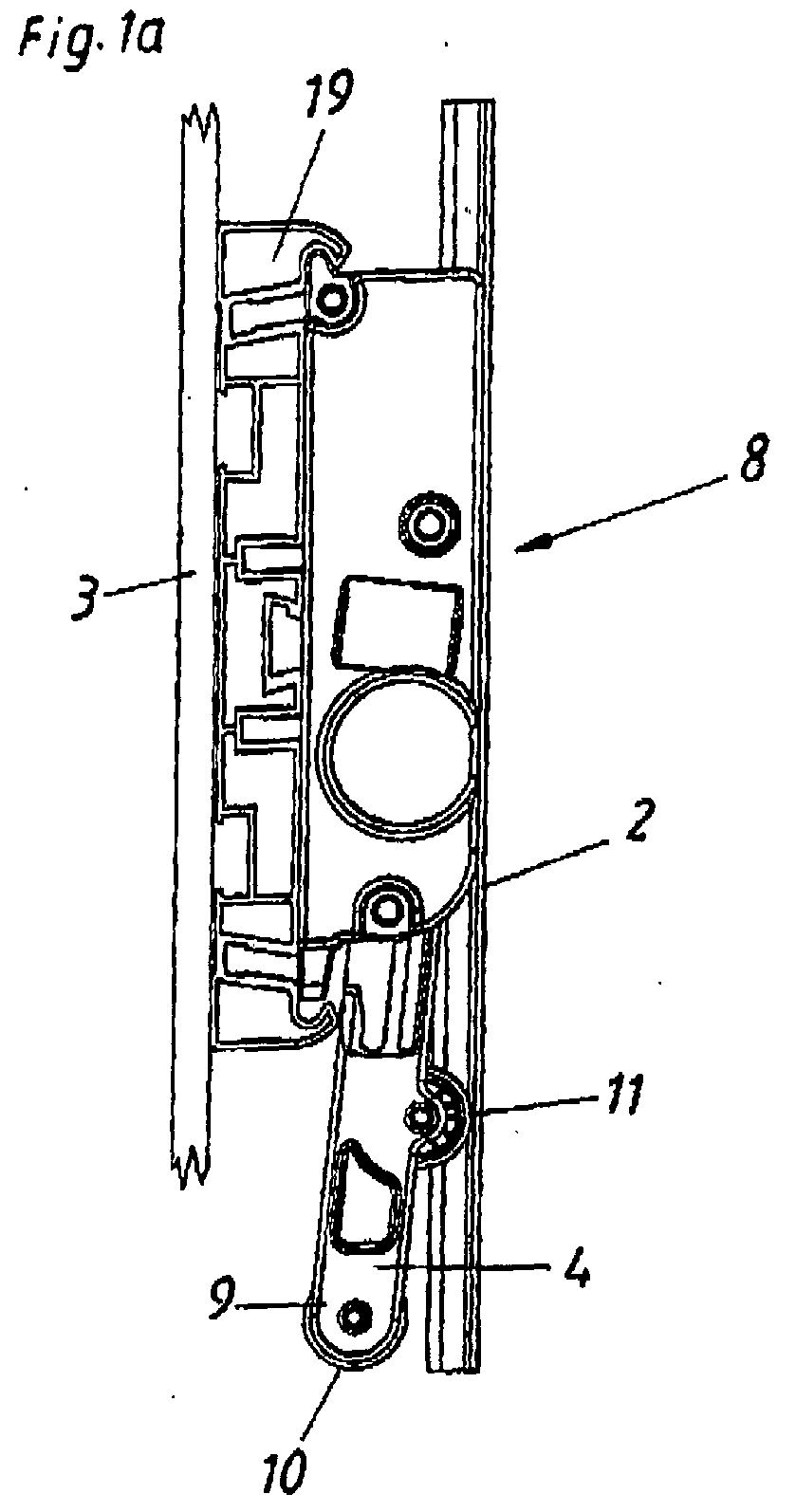
- Fig. 1 a shows in plan view an embodiment of an ejection device 8 according to the invention, which is fastened to a furniture body 3 via a carrier rail 19.
- the ejector 8 in this case has a pivotally mounted lever 4, wherein at the free end of the lever 9, a first roller 10 and in addition to approximately halfway between the articulation point of the lever 4 and the free end of the lever 9, a second roller 11 is arranged.
- the movable furniture part 2 of which only the rear panel is shown here, in its closed end position in the furniture body 3, whereby the lever 4 rests with the second roller 11 on the movable furniture part 2.
- Fig. 1b shows a perspective view of the ejection device 8, wherein the sake of clarity, the movable furniture part 2 has not been shown.
- Fig. 2a was the movable furniture part 2 already moved so far out of its closed end position in the furniture body 3 by the lever 4, that now also the arranged at the free end of the lever 9 first roller 10 comes into contact with the movable furniture part 2.
- Fig. 2b Fig. 12 is a perspective view of the ejection device 8 in this state.
- Fig. 3a and 3b show the situation just before the movable furniture part 2 moves completely away from the lever 4.
- the lever 4 is now on the arranged at the free end of the lever 9 first roller 10 with the movable furniture part 2 in contact, while the second roller 11, the movable furniture part 2 no longer contacted.
- the Fig. 4a and 4b show a lever 4 according to the invention, which consists of a first lever part 20 and a second lever part 21.
- the second lever part 21 is integral with the output 17 of an in Fig. 4 not shown transmission 13 is formed.
- On the first lever part 20 is at the free end of the lever 9, a roller 11 for acting on in Fig. 4 not shown movable furniture part 2 is provided.
- a second roller 10 is arranged approximately in the middle of the lever 4.
- a spring 18 is arranged, which is supported with its one spring end 36 on the second lever part 21 and with its other spring end 37 on the first Hebeiteil 20.
- the second lever part 20 is pretensioned with respect to the first lever part 21.
- the first lever member 20, a drive wheel 22 for a in Fig. 4 not shown potentiometer 15 for determining the position of the lever 4 is formed.
- Fig. 5c shows the respective position of the first lever part 20 and the second lever part 21, which are present when the in Fig. 5 not shown movable furniture part 2 is in its closed end position.
- the roller 10 is applied to the rear panel of the movable furniture part 2.
- Fig. 5a was the second Hebeiteil 21 via the output 22 of an In Fig. 5 not shown gear 13 is driven to achieve a discharge of the movable furniture part 2.
- the second lever 20 thus lays on the first Hebeiteil 21.
- the spring 18 supports the ejection process of the movable furniture part 2.
- Die Fig. 5b and 5d show perspective views of the Fig. 5a and 5c ,
- the Fig. 6a to 6d show a first embodiment of the third variant of the invention, which is characterized by a switch 4 arranged in the lever 4.
- the lever 4 has a first lever part 20 for applying a force in Fig. 6 not shown movable furniture part 2 and a second Hebeiteil 21, which also not with one shown drive unit 5 is in communication, on.
- a spring 25 is arranged between the two lever parts 20, 21.
- On the first lever part 20, a roller 10 is arranged.
- the switch 7 comprises a first contact 27 arranged on the first lever part 20 and a second contact 26 arranged on the second lever part 21 Fig. 6c and 6d shown state, the two contacts 26, 27 are lifted from each other. This corresponds to the inactive position of the switch 7.
- the furniture part 2 is also not shown in the closing direction, that is moved into the furniture body 3, not shown.
- the first lever part 20 is moved against the application of force to the spring 25.
- the two contacts 26, 27 come into contact, which for the sake of clarity does not close in detail, whereby via the lines 24, a trigger signal is transmitted to the drive unit 5.
- Fig. 7a to 7d show a second embodiment of the third variant of the invention, in which the lever 4 is integrally formed.
- the switch 7 is formed in this embodiment as a arranged at the free end of the lever 9 pressure switch.
- the Fig. 8a to 8c show various embodiments of the fourth variant of the invention. Shown is a gear 13, which serves to transmit power from the electric motor 29 to the second lever part 21. The power is transmitted via a in the Fig. 8 unrecognizable spindle 35 (recognizable in the Fig. 9a and 9b ), the gear 31, the further gear 33 and finally the output 17 of the transmission, which is formed integrally with the second lever member 21 in this embodiment.
- a potentiometer 15 here; rotary potentiometer
- the potentiometer 15 has three contacts 30 for connection or, for picking up electrical voltage.
- the potentiometer 15 is connected via a common axis with the middle stage of the transmission 13. At the in Fig. 8b illustrated embodiment, the potentiometer 15 is connected to the gear 31. In the particularly preferred mattersstieispiel the Fig. 8c the potentiometer 15 is connected to the second lever part 21.
- Fig. 9a to 9c show alternative views to those in the Fig. 8a to 8c illustrated embodiments.
- the 10a to 10f show an embodiment of the fifth variant of the invention.
- Fig. 10a shows in a side view a Tell a transmission 13, which comprises a slip clutch 14.
- the slip clutch 14 is in this embodiment of a spring ring 41, which expands bel excessive load and slides over the driving cam 42.
- This process is exemplary in the Fig. 10d to 10f shown.
- the Fig. 10g to 10i each show detailed representations of this process.
- Fig. 10b shows a perspective view of the part of the transmission 13th
- Fig. 10a to 10i shown part of the transmission 13 is in particular from the exploded view of Fig. 11b out.
- the driving cam 42 are form-fitting plugged onto the trained as a bolt 43 part of the gear 33.
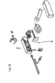
- dle Fig. 11a shows a perspective view of the complete transmission 13, which is driven by an electric motor 29 and in turn drives the second lever part 21.
- the Fig. 12 shows the in Fig. 11 illustrated ejector 8 with the first lever member 20 at partially removed housing in its attachment to a support rail 19th
- Fig. 13 shows a further exploded view of the in the Fig. 11a and 12 shown ejector 8, wherein the housing of the ejection device 8 is completely visible. Furthermore is in Fig. 13 the arrangement of a potentiometer 15 directly on a board 44, which houses all the circuits of the ejection device 8, recognizable. Via the output 22, the potentiometer 15 is in communication with the gear 13 and serves to measure the position of the lever 4.
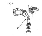
- Fig. 14 shows a further exploded view of the drive mechanism of the ejector 8 shown.
- a further embodiment of a Auskervarraum 8 according to the invention is shown, which is characterized in particular by the provided with the reference numeral 38 path measuring device.
- the Displacement measuring device 38 has a spring-loaded plunger 39 which can be acted on by a movable furniture part 2, not shown.
- the plunger 39 was pressed by the movable Switzerlandtell 2, not shown in the housing of the ejection device 8, which triggers the ejection process.
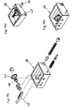
- This ejector is in Fig. 16 clearly displayed in an exploded view.
- Fig. 17 shows the exploded view of another embodiment of an ejection device 8 according to the invention, which differs from the example in Fig. 13 illustrated embodiment differs only in that a gear stage is less provided.
- a furniture 1 is shown with a designed as a drawer movable furniture part 2, Visible is a fixed to the furniture body 3 Wegmeß Rhein 38, which includes an encoder 45.
- a plunger 39 can be lifted by the rear side of the movable furniture part 2.
- the plunger 39 is engaged by the located in its closed end position movable furniture part 2.
- a slight movement outward of the movable furniture part 2 from its closed end position by a user allows the outward movement of the spring-loaded plunger 39, which is registered by the encoder 45.
- the path measuring device 38 then issues an In Fig. 18 not shown ejector 8 the command to eject the movable furniture part. 2
- Fig. 19a to 19c is the in Fig. 18 shown path measuring device 38 shown in detail. It can be seen that the plunger 39 is formed in the rear region as a rack 46 and a meshed with the disc 47 of the encoder 45 pinion 48 meshes. Visible is further a spring-loaded stop 49, which allows the distance measurement at a located in its closed end position movable furniture part 2, when this is pressed by a user on the remaining game for triggering in the direction of the furniture body 3.
- a further embodiment of an ejection device 8 according to the invention can be seen, which is characterized by a arranged on the furniture body 3 potentiometer 15.
- the actuator 16 of the potentiometer 15th 14 is connected via a driver 28 with the back of a movable furniture part 2. Moving out of the movable Möpfteils 2 from its closed end position takes over the driver 28 with the actuator 16 of the potentiometer 15, whereupon the potentiometer 15 commands the ejection of the movable furniture part 2 by the ejector 8.
- This process is in the Fig. 21a to 21c shown in a plan view
Landscapes
- Engineering & Computer Science (AREA)
- Mechanical Engineering (AREA)
- General Engineering & Computer Science (AREA)
- Drawers Of Furniture (AREA)
- Power-Operated Mechanisms For Wings (AREA)
- Mechanical Control Devices (AREA)
- Mechanisms For Operating Contacts (AREA)
- Toys (AREA)
Abstract
Description
- Die vorliegende Erfindung betrifft in einer ersten Variante eine Ausstoßvorrichtung für ein in oder an einem Möbelkorpus bewegbar gelagertes Möbelteil, mit einem schwenkbar gelagerten Hebel, wobei am freien Hebelende eine erste Laufrolle angeordnet ist.
- Der Stand der Technik zeigt folgendes:
- Die
US 6,669,250 B1 betrifft eine Ausstoßvorrichtung für ein in oder an einem Möbelkorpus bewegbar gelagertes Möbelteil (Türe oder Schublade) mit einem schwenkbar gelagerten Hebel, wobei am freien Hebelende eine Laufrolle angeordnet ist. - Die
EP 1 314 842 A1 hat eine Ausstoßvorrichtung für ein in oder an einem Möbelkorpus bewegbar gelagertes Möbelteil (Türe oder Schublade) zum Gegenstand mit einem schwenkbar gelagerten Hebel, wobei am freien Hebelende eine Laufrolle angeordnet ist. - Die
EP 1 374 732 A1 betrifft eine Ausstoßvorrichtung für ein in einem Möbelkorpus bewegbar gelagertes Möbelteil (Schublade) mit einer elektrischen Antriebseinheit, einer Steuer- bzw. Regeleinrichtung zum Steuern bzw. Regeln der Antriebseinheit und einem Getriebe zur Kraftübertragung von der Antriebseinheit auf den Ausstoßer. - Die
DE 29 24 145 A1 betrifft eine Ausstoßvorrichtung für einen in einem Haushaltsbackofen bewegbar gelagerten Backwagen mit einem schwenkbar gelagerten Hebel (Transporthebel) und mit einer elektrischen Antriebseinheit (Elektromotor). - Die
US 4,720,154 A beschreibt im Ausführungsbeispiel nach derFig. 10 eine Ausstoßvorrichtung für eine in einem Möbelkorpus (Geldausgabegerät) bewegbar gelagerte Schublade mit einem schwenkbar gelagerten Hebel und mit einer elektrischen Antriebseinheit (Elektromotor). - Die prioritäts-ältere
WO 2004/100718 A1 hat eine Ausstoßvorrichtung für ein in oder an einem Möbelkorpus bewegbar gelagertes Möbelteil (Türe oder Schublade) zum Gegenstand mit einem schwenkbar gelagerten Hebel, mit einer elektrischen Antriebseinheit und einer Steuer- bzw. Regeleinrichtung zum Steuem bzw. Regeln der Antriebseinheit. - Gattungsgemäße Ausstoßvorrichtungen haben das Problem, dass das Anfahrverhalten des durch den Hebel beaufschlagten bewegbaren Möbelteils vom Benutzer meist als äußerst träge empfunden wird. Um diesem Problem zu begegnen, ist die für den Hebel vorgesehene Antriebseinheit von der Leistung her häuflg überdimensioniert ausgebildet, um über den Hebel eine schnelle anfängliche Beschleunigung des bewegbaren Möbelteils zu erzielen. Nach der anfänglichen Beschleunigung des bewegbaren Möbelteils wäre an sich eine weit geringere Antriebsleistung ausreichend.
- Aufgabe der Erfindung ist es, eine Ausstoßvorrichtung zu schaffen, die dieses Problem nicht aufweist.
- Dies wird erfindungsgemäß dadurch erreicht, dass am Hebel beabstandet vom freien Hebelende eine zweite Laufrolle angeordnet ist.
- Durch die erfindungsgemäße Maßnahme wird eine gleichmäßige Belastung der den Hebel antreibenden Antriebseinhelt über die gesamte Ausstoßstrecke erreicht. Der schwenkbar gelagerte Hebel kommt zuerst mit der beabstandet vom freien Hebelende angeordneten zweiten Laufrolle mit dem bewegbaren Möbeiteil in Kontakt, wodurch das auf das bewegbare Möbelteil ausgeübte Drehmoment kleiner ist als bei sofortiger Kontaktierung mit der am freien Hebelende angeordneten Laufrolle. Dadurch wird die Antriebseinheit, welche einen Elektromotor umfassen kann, während der anfänglichen Beschleunigung des bewegbaren Möbelteils mit einem geringeren Drehmoment belastet. Hierdurch ergibt sich ein günstigeres Anfahrverhalten. Vom Benutzer wird dies als schwungvollere anfängliche Beschleunigung des bewegbaren Möbelteils wahrgenommen.
- Nach der anfänglichen Beschleunigung des bewegbaren Möbelteils kommt der Hebel mit der am freien Hebelende angeordneten ersten Laufrolle mit dem bewegbaren Nöbelteil in Kontakt und kann so über das größere Drehmoment (aufgrund des längeren Hebelarms) eine größere Kraft auf das bewegbare Möbelteil ausüben. Da die Trägheit des bewegbaren Möbelteils bereits überwunden ist, wird die Antriebseinheit jetzt trotz des größeren Drehmoments in etwa nur gleich stark belastet, wie während der anfänglichen Beschleunigungsphase. Insgesamt ergibt sich daher eine Gleichverteilung der Last der Antriebseinheit über die gesamte Ausstoßstrecke des bewegbaren Möbeiteils.
- Bei einer besonders bevorzugten Ausführungsform der Erfindung ist vorgesehen, dass die zweite Laufrolle in einem Abstand von annähernd einer halben Hebellänge vom freien Hebelende am Hebel angeordnet ist. Dies ergibt eine in der Praxis zufriedenstellende Verteilung der auf die Antriebseinheit wirkenden Lastkräfte.
- Eine weitere, zweite Variante der Erfindung betrifft eine Ausstoßvorrichtung für ein in oder an einem Möbelkorpus bewegbar gelagertes Möbelteil, insbesondere nach Anspruch 1 oder 2, mit einem schwenkbar gelagerten Hebel und einer insbesondere elektrischen Antriebseinheit zum Antreiben des Hebels.
- Der Betrieb derartiger Ausstoßvorrichtungen ist mit einer für den Benutzer unangenehmen Lärmentwicklung verbunden. Neben dem anfänglichen Anschlagsgeräusch, das sich bei der Kontaktierung des schwenkbar gelagerten Hebels mit dem bewegbaren Möbelteil ergibt, ist auch der weitere Betrieb der Ausstoßvorrichtung mit einer unangenehmen Lärmentwicklung verbunden.
- Aufgabe dieser Variante der Erfindung ist es, eine gattungsgemäße Ausstoßvorrichtung zu schaffen, die sich durch eine geringere Lärmentwicklung auszeichnet.
- Dies wird erfindungsgemäß dadurch erreicht, dass der Hebel wenigstens einen ersten Hebelteil und einen zweiten Hebelteil aufweist, wobei der erste Hebelteil mit dem bewegbaren Möbelteil kontaktierbar ist und der zweite Hebelteil durch die Antriebseinheit antreibbar ist und dass der erste Hebelteil mit dem zweiten Hebelteil begrenzt bewegbar gekoppelt ist, wobei der erste Hebelteil in Bezug auf den zweiten Hebelteil durch einen Kraftspeicher vorgespannt ist,
- Durch die zweiteilige Ausführung des Hebels ergibt sich ein Spiel zwischen dem ersten und dem zweiten Hebelteil. Durch die Vorspannung des ersten Habelteils in Bezug auf den zweiten Hebelteil wird der erste Hebelteil an das bewegbare Möbelteil angepresst. Durch die Reaktionskraft wird der zweite Hebelteil vom ersten Hebelteil weggedrückt, wodurch auch die mit dem zweiten Hebelteil in Kontakt stehenden Teile der Antriebseinheit unter Spannung gesetzt werden. Überraschenderweise hat sich herausgestellt, dass dies zu einer Verringerung des Betriebslärms der Ausstoßvorrichtung führt.
- Bei einer vorteilhaften Ausführungsform dieser Variante der Erfindung ist vorgesehen, dass der erste Hebelteil in Bezug auf den zweiten Hebelteil durch eine Feder vorgespannt ist. Dies stellt eine konstruktiv besonders einfache Realisierung der erfindungsgemäßen Maßnahme dar.
- Eine weitere, dritte Variante der Erfindung betrifft eine Ausstoßvorrichtung für ein in oder an einem Möbelkorpus bewegbar gelagertes Möbelteil, insbesondere nach einem der Ansprüche 1 bis 4, mit einem schwenkbar gelagerten Hebel zum Ausstoßen des bewegbaren Möbelteils, einer insbesondere elektrischen Antriebseinheit zum Abtreiben des Hebels und einer Steuer- bzw. Regeleinrichtung zum Steuern bzw. Regeln der Antriebseinheit.
- Bei derartigen Ausstoßvorrichtungen stellt sich das Problem der optimalen Auslösung der Ausstoßvorrichtung durch den Benutzer. In dieser Hinsicht ist eine möglichst intuitive Bedienbarkeit der Ausstoßvorrichtung von Vorteil.
- Aufgabe dieser Variante der Erfindung ist es daher, eine Ausstoßvorrichtung zu schaffen, die sich durch eine intuitive Auslösbarkeit auszeichnet.
- Dies wird erfindungsgemäß dadurch erreicht, dass am oder im Hebel ein Schalter zum Auslösen der Ausstoßvorrichtung angeordnet ist, wobei die Signale des Schalters wenigstens der Steuer- bzw. Regeleinrichtung zuführbar sind.
- Die erfindungsgemäße Maßnahme gestattet die Auslösung der Ausstoßvorrichtung durch ein Andrücken der Frontblende des bewegbaren Möbelteils in den Möbelkorpus hinein. Hierfür ist natürlich in der geschlossenen Endlage des bewegbaren Möbelteils 5 genügend Spiel zu lassen. Sobald das bewegbare Möbelteil den am Hebel angeordneten Schalter kontaktiert, sendet der Schalter das Auslösesignal an die Steuer- bzw. Regeleinrichtung der Ausstoßvorrichtung.
- Eine besonders vorteilhafte Ausführungsform dieser Variante der Erfindung ergibt sich bei einer Kombination mit der zweiten Variante der Erfindung. Weist der Hebel wenigstens einen ersten und einen zweiten Hebelteil auf, so kann nämlich vorgesehen sein, dass der Schalter wenigstens zwei Kontakte aufweist, wobei der erste Kontakt am ersten Hebelteil und der zweite Kontakt am zweiten Hebelteil angeordnet ist.
- Durch ein Andrücken des bewegbaren Möbelteils in den Möbelkorpus hinein, wird der am bewegbaren Möbelteil anliegende erste Hebelteil in Richtung des zweiten Hebelteils gedrückt, wodurch sich die beiden Kontakte berühren und den Stromkreis schließen.
- Vorzugsweise ist dabei zwischen den beiden Hebelteilen zur Erzeugung einer Vorspannung ein Kraftspeicher angeordnet.
- Alternativ könnte natürlich auch vorgesehen sein, dass der Schalter einen Druckschalter umfasst, der vorzugsweise am freien Hebelende angeordnet ist. Eine zweiteilige Ausführung des Hebels kann bei dieser Ausführungsform entfallen.
- Eine weitere, vierte Variante der Erfindung betrifft eine Ausstoßvorrichtung für ein in oder an einem Möbelkorpus bewegbar gelagertes Möbelteil, insbesondere nach einem der Ansprüche 1 bis 8, mit einem Ausstoßer zum Ausstoßen des bewegbaren Mäbefteils, einer insbesondere elektrischen Antriebseinheit, einem Getriebe zur Kraftübertragung von der Antriebseinheit auf den Ausstoßer und einer Steuer- bzw. Regeleinrichtung zum Steuern bzw. Regeln der Antriebseinheit.
- Bei derartigen Ausstoßvorrichtungen ist es häufig wünschenswert, die Position des Ausstoßers zu kennen, um beispielsweise das Ausstoßprofil in Abhängigkeit von der Position gestalten zu können. Ebenso kann vorgesehen sein, die Ausstoßvorrichtung bei einer anfänglichen, durch einen Benutzer verursachten Verschiebung des bewegbaren Möbelteils und damit des Ausstoßers auszulösen.
- Aufgabe dieser Variante der Erfindung ist es daher, eine Ausstoßvorrichtung zu schaffen, bei der die Position des Ausstoßers feststellbar ist.
- Dies wird erfindungsgemäß dadurch erreicht, dass die Ausstoßvorrichtung ein Potentiometer umfasst, wobei die Signale des Potentiometers wenigstens der Steuer- bzw. Regeleinrichtung zuführbar sind und dass das Stellglied des Potentiometers mit dem Getriebe gekoppelt ist.
- Alle Potentiometer haben gegenüber anderen Wegmesseinrichtungen den Vorteil, dass sie die Position des Ausstoßers absolut messen, wodurch keine Notwendigkeit zur Initialisierung der Wegmesseinrichtung besteht.
- Ist vorgesehen, dass der Ausstoßer einen Hebel umfasst, so ist es besonders vorteilhaft, wenn weiters vorgesehen ist, dass der Abtrieb des Getriebes einstückig mit dem Hebel ausgebildet ist.
- In diesem Fall kann das Stellglied des Potentiometers direkt mit dem Hebel gekoppelt sein. Dies weist unter anderem den Vorteil auf, dass, falls vorgesehen ist, dass das Getriebe eine Rutschkupplung umfasst, trotz eines Durchrutschens des Hebels die Position des Hebels korrekt bestimmt werden kann.
- Insbesondere bei einem schwenkbar gelagerten Hebel ist es zur Vermeidung einer Bewegungsumwandlung besonders vorteilhaft, wenn vorgesehen ist, dass das Potentiometer als Drehpotentiometer ausgebildet ist.
- Eine weitere, fünfte Variante der Erfindung betrifft eine Ausstoßvorrichtung für ein in oder an einem Möbelkorpus bewegbar gelagertes Möbelteil, insbesondere nach einem der Ansprüche 1 bis 13, mit einem Ausstoßer zum Ausstoßen des bewegbaren Möbelteils, einer insbesondere elektrischen Antriebseinheit und einem Getriebe zur Kraftübertragung von der Antriebseinheit auf den Ausstoßer.
- Derartige Ausstoßvorrichtungen haben das Problem, dass es häufig zu einer Beschädigung des Getriebes in Folge einer missbräuchlichen Benutzung der Ausstoßvorrichtung kommt. Beispielsweise werden ausgestoßene bewegbare Mäbelteile vom Benutzer zum Schließen oft mit einer beträchtlichen Kraftentwicklung in Richtung des Möbelkorpus gestoßen. Trifft das bewegbare Möbelteil auf den Ausstoßer der Ausstoßvorrichtung, so überträgt sich diese Kraft auf das Getriebe der Ausstoßvorrichtung, was im schlimmsten Fall zu deren Zerstörung führen kann.
- Aufgabe der Erfindung ist es daher, eine gattungsgemäße Ausstoßvorrichtung zu schaffen, die dieses Problem nicht aufweist.
- Dies wird erfindungsgemäß dadurch erreicht, dass das Getriebe eine Rutschkupplung umfasst.
- Übersteigt die vom Ausstoßer auf das Getriebe übertragene Kraftentwicklung einen durch die konstruktive Ausführung der Rutschkupplung bedingten Grenzwert, so kommt es zu einem Durchrutschen des mit der Rutschkupplung gekoppelten Getriebeteils, was eine Beschädigung des Getriebes verhindert.
- Die vorliegende Erfindung betrifft auch ein Möbel mit einem bewegbaren Möbelteil, insbesondere Schublade oder Türe, mit einer Ausstoßvorrichtung nach einer der vorgenannten Varianten der Erfindung.
- Zur Auslösung der Ausstoßvorrichtung kann die Anordnung einer Wegmesseinrichtung am bzw. im Möbel vorgesehen sein, wobei die Ausstoßvorrichtung durch die Wegmesseinrichtung auslösbar ist.
- Um einen möglichst einfachen Einbau in ein erfindungsgemäßes Möbel zu erlauben, ist es besonders vorteilhaft, wenn vorgesehen ist, dass die Wegmesseinrichtung an bzw. in der Ausstoßvorrichtung angeordnet ist.
- Es kann aber auch vorgesehen sein, dass die Wegmesseinrichtung am bzw. im Möbelkorpus angeordnet ist.
- Eine mögliche Ausführungsform der Erfindung, welche sich durch ihre Einfachheit auszeichnet, sieht vor, dass die Wegmesseinrichtung einen vom bewegbaren Möbelteil beaufschlagbaren Stößel umfasst.
- Soll die Ausstoßvorrichtung durch eine vom Benutzer auf das bewegbare Möbelteil aufgebrachte Zugkraft auslösbar sein, so kann vorteilhafterweise vorgesehen sein, dass die Wegrnesseinrichtung einen mit dem bewegbaren Möbelteil koppelbaren Mitnehmer aufweist.
- Die Wegmesseinrichtung kann sowohl als absolute Messeinrichtung, als auch als inkrementelle Messeinrichtung ausgebildet sein.
- Im ersten Fall kann die Wegmesseinrichtung beispielsweise ein Potentiometer umfassen. Im zweiten Fall kann die Wegmesseinrichtung beispielsweise einen Encoder umfassen.
- Weitere Vorteile und Einzelheiten der Erfindung ergeben sich anhand der nachfolgenden Figurenbeschreibung, Dabei zeigen:
- Fig. 1 bis 3
- Darstellungen eines Ausführungsbeispiels der ersten Variante der Erfindung in Draufsicht sowie in perspektivischer Ansicht bei verschiedenen Stellungen des Hebels der Ausstoßvorrichtung.
- Fig. 4 bis 5
- ein Ausführungsbeispiel der zweiten Variante der Erfindung in verschiedenen Ansichten,
- Fig. 6a bis 6d
- Ansichten eines Ausführungsbeispiels der dritten Variante der Erfindung,
- Fig. 7a bis 7d
- ein weiteres Ausführungsbeispiel der dritten Variante der Erfindung,
- Fig. 8 bis 9
- verschiedene Ansichten eines Ausführungsbeispiels der vierten Variante der Erfindung,
- Fig. 10 bis 11
- verschiedene Ansichten eines Ausführungsbeispiels der fünften Variante der Erfindung,
- Fig. 12
- die perspektivische Ansicht eines weiteren Ausführungsbeispiels einer erfindungsgemäßen Ausstoßvorrichtung,
- Fig 13
- die in
Fig. 12 gezeigte Ausstoßvorrichtung in Explosionsdarstellung, - Fig. 14
- einige Komponenten der in
Fig. 13 dargestellten Ausstoßvorrichtung in perspektivischer Ansicht sowie in Explosionsdarstellung, - Fig. 15a bis 15c
- 9 eine Schnittdarstellung eines weiteren Ausführungsbeispiels einer erfindungsgemäßen Ausstoßvorrichtung,
- Fig. 16
- eine Explosionsdarstellung der in
Fig. 15 dargestellten Ausstoßvorrichtung, - Fig. 17
- eine Explosionsdarstellung eines weiteren Ausführungsbeispiels einer erfindungsgemäßen Ausstoßvorrichtung,
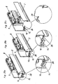
- Fig. 18a bis 18d
- ein Ausführungsbeispiel eines erfindungsgemäßen Möbels,
- Fig. 19a bis 19c
- ein Ausführungsbeispiel einer Wegmesseinrichtung in zwei perspektivischen Ansichten sowie in einer Explosionsansicht,
- Fig. 20a bis 20c
- In perspektivischer Ansicht ein weiteres Ausführungsbeispiel einer erfindungsgemäßen Ausstoßvorrichtung und
- Fig. 21a bis 21c
- eine Draufsicht auf die in
Fig. 20 dargestellte Ausstoßvorrichtung. -
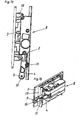
Fig. 1 a zeigt in Draufsicht ein Ausführungsbeispiel einer erfindungsgemäßen Ausstoßvorrichtung 8, welche über eine Trägerschiene 19 an einem Möbelkorpus 3 befestigt ist. Die Ausstoßvorrichtung 8 weist dabei einen schwenkbar gelagerten Hebel 4 auf, wobei am freien Hebelende 9 eine erste Laufrolle 10 und zusätzlich auf annähemd halber Strecke zwischen dem Anlenkpunkt des Hebels 4 und dem freien Hebelende 9 eine zweite Laufrolle 11 angeordnet ist. Bei dem inFig. 1a dargestellten Zustand befindet sich das bewegbare Möbelteil 2, von dem hier nur die Rückblende dargestellt ist, in seiner geschlossenen Endlage im Möbelkorpus 3, wodurch der Hebel 4 mit der zweiten Laufrolle 11 am bewegbaren Möbelteil 2 anliegt. -
Fig. 1b zeigt eine perspektivische Ansicht der Ausstoßvorrichtung 8, wobei der besseren Übersichtlichkeit halber das bewegbare Möbelteil 2 nicht dargestellt wurde. - In
Fig. 2a wurde das bewegbare Möbelteil 2 durch den Hebel 4 bereits so weit aus seiner geschlossenen Endlage im Möbelkorpus 3 herausbewegt, dass nun auch die am freien Hebelende 9 angeordnete erste Laufrolle 10 mit dem bewegbaren Möbelteil 2 in Kontakt kommt. -
Fig. 2b stellt eine perspektivische Ansicht der Ausstoßvorrichtung 8 in diesem Zustand dar. - Die
Fig. 3a und 3b zeigen die Situation, kurz bevor sich das bewegbare Möbelteil 2 vollständig vom Hebel 4 wegbewegt. Der Hebel 4 ist nunmehr über die am freien Hebelende 9 angeordnete ersten Laufrolle 10 mit dem bewegbaren Möbelteil 2 in Kontakt, während die zweite Laufrolle 11 das bewegbare Möbelteil 2 nicht mehr kontaktiert. - Die
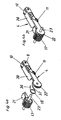
Fig. 4a und 4b zeigen einen erfindungsgemäßen Hebel 4, der aus einem ersten Hebelteil 20 und einem zweiten Hebelteil 21 besteht. Der zweite Hebelteil 21 ist einstückig mit dem Abtrieb 17 eines inFig. 4 nicht dargestellten Getriebes 13 ausgebildet. Am ersten Hebelteil 20 ist am freien Hebelende 9 eine Laufrolle 11 zur Beaufschlagung eines inFig. 4 nicht dargestellten bewegbaren Möbelteils 2 vorgesehen. Weiters Ist annähernd in der Mitte des Hebels 4 eine zweite Laufrolle 10 angeordnet. Zwischen dem ersten Hebelteil 20 und dem zweiten Hebelteil 21 ist eine Feder 18 angeordnet, welche sich mit ihrem einen Federende 36 am zweiten Hebelteil 21 und mit ihrem anderen Federende 37 am ersten Hebeiteil 20 abstützt. Dadurch wird das zweite Hebelteil 20 in Bezug auf das erste Hebelteil 21 vorgespannt. In diesem Ausführungsbeispiel ist am ersten Hebelteil 20 ein Antriebsrad 22 für ein inFig. 4 nicht näher dargestelltes Potentiometer 15 zur Positionsbestimmung des Hebels 4 ausgebildet. -
Fig. 5c zeigt die jeweilige Lage des ersten Hebelteils 20 und des zweiten Hebelteils 21, die vorliegen, wenn sich das inFig. 5 nicht dargestellte bewegbare Möbelteil 2 in seiner geschlossenen Endlage befindet. Die Laufrolle 10 liegt dabei an der Rückblende des bewegbaren Möbelteils 2 an. InFig. 5a wurde das zweite Hebeiteil 21 über den Abtrieb 22 eines InFig. 5 nicht dargestellten Getriebes 13 angetrieben bewegt, um eine Ausstoßung des bewegbaren Möbelteils 2 zu erzielen. Der zweite Hebelieil 20 llegt dadurch am ersten Hebeiteil 21 an. Die Feder 18 unterstützt dabei den Ausstoßvorgang des bewegbaren Möbelteils 2. DieFig. 5b und 5d zeigen perspektivische Ansichten zu denFig. 5a und 5c . - Die
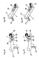
Fig. 6a bis 6d zeigen ein erstes Ausführungsbeispiel der dritten Variante der Erfindung, welche sich durch einen im Hebel 4 angeordneten Schalter 7 auszeichnet. Wie in dem vorbesprochenen Ausführungsbeispiel weist der Hebel 4 einen ersten Hebelteil 20 zur Kraftbeaufschlagung eines inFig. 6 nicht dargestellten bewegbaren Möbelteils 2 und einen zweiten Hebeiteil 21, welcher mit einer ebenfalls nicht dargestellten Antriebseinheit 5 in Verbindung steht, auf. Eine Feder 25 ist zwischen den beiden Hebelteilen 20, 21 angeordnet. Am ersten Hebelteil 20 ist eine Laufrolle 10 angeordnet. Der Schalter 7 umfasst einen am ersten Hebelteil 20 angeordneten ersten Kontakt 27 und einen am zweiten Hebelteil 21 angeordneten zweiten Kontakt 26. Bei dem in denFig. 6c und 6d dargestellten Zustand sind die beiden Kontakte 26, 27 voneinander abgehoben. Dies entspricht der inaktiven Stellung des Schalters 7. Durch einen nicht dargestellten Benutzer wird das ebenfalls nicht dargestellte Möbelteil 2 in Schließrichtung, das heißt in den nicht dargestellten Möbelkorpus 3 hineinbewegt. Dadurch wird der erste Hebelteil 20 gegen die Kraftbeaufschlagung der Feder 25 bewegt. Dadurch kommen die beiden Kontakte 26, 27 in Berührung, was einen der Übersichtlichkeit halber nicht näher dargestellten schließt, wodurch über die Leitungen 24 ein Auslösesignal an die Antriebseinheit 5 weitergegeben wird. - Die
Fig. 7a bis 7d zeigen ein zweites Ausführungsbeispiel der dritten Variante der Erfindung, bei dem der Hebel 4 einstückig ausgebildet ist. Der Schalter 7 ist in diesem Ausführungsbeispiel als ein am freien Hebelende 9 angeordneter Druckschalter ausgebildet. - Die
Fig. 8a bis 8c zeigen verschiedene Ausführungsbeispiele der vierten Variante der Erfindung. Dargestellt ist ein Getriebe 13, welches zur Kraftübermittlung von dem Elektromotor 29 auf den zweiten Hebelteil 21 dient. Die Kraftübermittlung erfolgt dabei über eine in denFig. 8 nicht erkennbare Spindel 35 (erkennbar in denFig. 9a und 9b ), das Zahnrad 31, das weitere Zahnrad 33 und schließlich den Abtrieb 17 des Getriebes, der in diesem Ausführungsbeispiel einstückig mit dem zweiten Hebelteil 21 ausgebildet ist. Erfindungsgemäß ist in jeder derFig. 8a bis 8c ein Potentiometer 15 (hier; Drehpotentiometer) mit dem Getriebe 13 verbunden. Das Potentiometer 15 weist dabei drei Kontakte 30 zum Anschluss bzw, zum Abgreifen von elektrischer Spannung auf. Bei dem inFig. 8a dargestellten Ausführungsbeispiel ist das Potentiometer 15 über eine gemeinsame Achse mit der mittleren Stufe des Getriebes 13 verbunden. Bei dem inFig. 8b dargestellten Ausführungsbeispiel ist das Potentiometer 15 mit dem Zahnrad 31 verbunden. Bei dem besonders bevorzugten Ausführungstieispiel derFig. 8c ist das Potentiometer 15 mit dem zweiten Hebelteil 21 verbunden. - Die
Fig. 9a bis 9c zeigen alternative Ansichten zu den in denFig. 8a bis 8c dargestellten Ausführungsbeispielen. - Die
Fig. 10a bis 10f zeigen ein Ausführungsbeispiel der fünften Variante der Erfindung.Fig. 10a zeigt in einer Seitenansicht einen Tell eines Getriebes 13, welches eine Rutschkupplung 14 umfasst. Die Rutschkupplung 14 besteht in diesem Ausführungsbeispiel aus einem Federring 41, welcher sich bel übermäßiger Belastung aufweitet und über die Mitnahmenocken 42 gleitet. Dieser Vorgang ist beispielhaft in denFig. 10d bis 10f dargestellt. DieFig. 10g bis 10i zeigen jeweils Detaildarstellungen zu diesem Vorgang.Fig. 10b zeigt eine perspektivische Ansicht des Teils des Getriebes 13. - Der Aufbau des in den
Fig. 10a bis 10i dargestellten Teils des Getriebes 13 geht insbesondere aus der Explosionsdarstellung derFig. 11b hervor. Auf einem gemeinsamen Stift 23 sind dabei das Zahnrad 33, das weitere Zahnrad 32, welches drehfest mit dem Federring 40 verbunden ist, und die Mitnahmenocken 42 angeordnet. Die Mitnahmenocken 42 sind formschlussig auf den als Bolzen 43 ausgebildeten Teil des Zahnrads 33 aufgesteckt. DleFig. 11a zeigt eine perspektivische Ansicht des vollständigen Getriebes 13, welches von einem Elektromotor 29 angetrieben wird und seinerseits den zweiten Hebelteil 21 antreibt. - Die
Fig. 12 zeigt die inFig. 11 dargestellte Ausstoßvorrichtung 8 mit dem ersten Hebelteil 20 bei teilweise entferntem Gehäuse in ihrer Befestigung an einer Trägerschiene 19. -
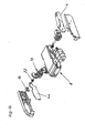
Fig. 13 zeigt eine weitere Explosionsdarstellung der in denFig. 11a und12 dargestellten Ausstoßvorrichtung 8, wobei auch das Gehäuse der Ausstoßvorrichtung 8 vollständig erkennbar ist. Weiters ist inFig. 13 die Anordnung eines Potentiometers 15 direkt auf einer Platine 44, welche alle Schaltkreise der Ausstoßvorrichtung 8 beherbergt, erkennbar. Über den Abtrieb 22 steht das Potentiometer 15 mit dem Getriebe 13 in Verbindung und dient der Positionsmessung des Hebels 4.Fig. 14 zeigt eine weitere Explosionsdarstellung des Antriebsmechanismus der dargestellten Ausstoßvorrichtung 8. - In den
Fig. 15a bis 15c ist ein weiteres Ausführungsbeispiel einer erfindungsgemäßen Ausstoßvarrichtung 8 dargestellt, welches sich insbesondere durch die mit dem Bezugszeichen 38 versehene Wegemesseinrichtung auszeichnet. Die Wegmesseinrichtung 38 weist einen von einem nicht dargestellten bewegbaren Möbelteil 2 beaufschlagbaren federbelasteten Stößel 39 auf. InFig. 15a wurde der Stößel 39 durch das nicht dargestellte bewegbare Mäbeltell 2 in das Gehäuse der Ausstoßvorrichtung 8 eingedrückt, was den Ausstoßvorgang auslöst. Diese Ausstoßvorrichtung ist inFig. 16 in einer Explosionsdarstellung übersichtlich dargestellt. - Die
Fig. 17 zeigt die Explosionsdarstellung eines weiteren Ausführungsbeispiels einer erfindungsgemäßen Ausstoßvorrichtung 8, welches sich von dem beispielsweise inFig. 13 dargestellten Ausführungsbeispiel nur dadurch unterscheidet, dass eine Getriebestufe weniger vorgesehen ist. - In den
Fig. 18a bis 18d ist ein Möbel 1 mit einem als Schublade ausgebildeten bewegbaren Möbelteil 2 dargestellt, Erkennbar ist eine am Möbelkorpus 3 befestigte Wegmesseinrichtung 38, welche einen Encoder 45 umfasst. Ein Stößel 39 ist durch die Rückseite des bewegbaren Möbelteils 2 kranbeaufschlagbar. In der inFig. 18a dargestellten Stellung ist das Stößel 39 durch das sich in seiner geschlossenen Endlage befindende bewegbaren Möbelteil 2 eingerückt Eine geringfügige Herausbewegung des bewegbaren Möbelteils 2 aus seiner geschlossenen Endlage durch einen Benutzer gestattet die Herausbewegung des federbeaufschlagten Stößels 39, was vom Encoder 45 registriert wird. Die Wegmesseinrichtung 38 erteilt daraufhin einer InFig. 18 nicht dargestellten Ausstoßvorrichtung 8 den Befehl zum Ausstoßen des bewegbaren Möbelteils 2. - In den
Fig. 19a bis 19c ist die inFig. 18 gezeigte Wegmesseinrichtung 38 im Detail dargestellt. Erkennbar ist, dass der Stößel 39 im hinteren Bereich als Zahnstange 46 ausgebildet ist und ein mit der Scheibe 47 des Encoders 45 verbundenes Ritzel 48 kämmt. Erkennbar ist weiters ein gefederter Anschlag 49, der die Wegmessung bei einem In seiner geschlossenen Endlage befindlichen bewegbaren Möbelteil 2 gestattet, wenn dieses durch einen Benutzer über das verbleibende Spiel zur Auslösung in Richtung des Möbelkorpus 3 gedrückt wird. - In den
Fig. 20a bis 20c ist ein weiteres Ausführungsbeispiel einer erfindungsgemäßen Ausstoßvorrichtung 8 erkennbar, welches sich durch ein am Möbelkorpus 3 angeordnetes Potentiometer 15 auszeichnet. Das Stellglied 16 des Potentiometers 15 14 ist über einen Mitnehmer 28 mit der Rückseite eines bewegbaren Möbelteils 2 verbunden. Das Herausbewegen des bewegbaren Möbeiteils 2 aus seiner geschlossenen Endlage nimmt über die Mitnehmer 28 das Stellglied 16 des Potentiometers 15 mit, worauf das Potentiometer 15 die Ausstoßung des bewegbaren Möbelteils 2 durch die Ausstoßvorrichtung 8 befiehlt. Dieser Vorgang ist in denFig. 21a bis 21c in einer Draufsicht dargestellt
Claims (14)
- Ausstoßvorritchtung für ein in oder an einem Möbelkorpus bewegbar gelagertes Möbelteil mit einem Ausstoßer zum Ausstoßen des bewegbaren Möbelteils, einer insbesondere elektrischen Antriebseinheit, einem Getriebe zur Kraftübertragung von der Antriebseinheit auf den Ausstoßer und einer Steuer- bzw, Regeleinrichtung zum Steuern bzw. Regeln der Antriebseinheit, dadurch gekennzeichnet. dass die Ausstoßvorrichtung (8) ein Potentiometer (15) umfasst, wobei die Signale des Potentiometers (15) wenigstens der Steuer- bzw. Regeleinrichtung (6) zuführbar sind und dass das Stellglied (16) des Potentiometers (15) mit dem Getriebe (13) gekoppelt ist.
- Ausstoßvorrichtung nach Anspruch 1, dadurch gekennzeichnet, dass der Ausstoßer einen Hebel (4) umfasst.
- Ausstoßvorrichtung nach Anspruch 2, dadurch gekennzeichnet, dass der Abtrieb (17) des Getriebes (13) einstückig mit dem Hebel (4) ausgebildet ist.
- Ausstoßvorrichtung nach Anspruch 3, dadurch gekennzeichnet, dass das Siellglied (16) des Potentiometers (15) mit dem Hebel (4) gekoppelt ist.
- Ausstoßvorrichtung nach einem der Ansprüche 1 bis 4, dadurch gekennzeichnet, dass das Potentiometer (15) als Drehpotentiometer ausgebildet ist.
- Möbel mit einem bewegbaren Möbelteil, insbesondere Schublade oder Türe, gekennzeichnet durch eine Ausstoßvorrichtung (8) nach einem der Ansprüche 1 bis 5.
- Möbel nach Anspruch 6, dadurch gekennzeichnet, dass am bzw, im Möbel (1) eine Wegmesseinrichtung (38) angeordnet ist und dass die Ausstoßvorrichtung (8) durch die Wegmesseinrichtung (38) auslösbar ist.
- Möbel nach Anspruch 7, dadurch gekennzeichnet, dass die Wegmesseinrichtung (38) an bzw. in der Ausstoßvorrichtung (8) angeordnet ist.
- Möbel nach Anspruch 7, dadurch gekennzeichnet, dass die Wegmesseinrichtung (38) an bzw, im Möbelkorpus (3) angeordnet ist.
- Möbel nach einem der Ansprüche 7 bis 9, dadurch gekennzeichnet, dass die Wegmesseinrichtung (38) einen vom bewegbaren Möbelteil (2) beaufschlagbaren Stößel (39) umfasst.
- Möbel nach einem der Ansprüche 7 bis 10, dadurch gekennzeichnet, dass die Wegmesseinrichtung (38) einen mit dem bewegbaren Möbelteil (2) koppelbaren Mitnehmer (28) aufweist.
- Möbel nach einem der Ansprüche 7 bis 11, dadurch gekennzeichnet, dass die Wegmesseinrichtung (38) einen Encoder (39) umfasst.
- Möbel nach einem der Ansprüche 7 bis 11, dadurch gekennzeichnet, dass die Wegmesseinrichtung (38) ein Potentiometer (15) umfasst.
- Möbel nach einem der Ansprüche 7 bis 13, dadurch gekennzeichnet, dass die Wegmesseinrichtung (38) einen gefederten Anschlag (49) aufweist, der die Wegmessung bei einem in seiner geschlossenen Endlage befindlichen bewegbaren Möbelteil (2) gestattet.
Applications Claiming Priority (2)
| Application Number | Priority Date | Filing Date | Title |
|---|---|---|---|
| AT0137904A AT413472B (de) | 2004-08-16 | 2004-08-16 | Ausstossvorrichtung für ein bewegbares möbelteil |
| EP05752348A EP1804613B1 (de) | 2004-08-16 | 2005-06-24 | Ausstossvorrichtung für ein bewegbares möbelteil |
Related Parent Applications (2)
| Application Number | Title | Priority Date | Filing Date |
|---|---|---|---|
| EP05752348A Division EP1804613B1 (de) | 2004-08-16 | 2005-06-24 | Ausstossvorrichtung für ein bewegbares möbelteil |
| EP05752348.2 Division | 2005-06-24 |
Publications (2)
| Publication Number | Publication Date |
|---|---|
| EP2305068A1 true EP2305068A1 (de) | 2011-04-06 |
| EP2305068B1 EP2305068B1 (de) | 2012-08-22 |
Family
ID=34842300
Family Applications (4)
| Application Number | Title | Priority Date | Filing Date |
|---|---|---|---|
| EP10013680A Expired - Lifetime EP2305068B1 (de) | 2004-08-16 | 2005-06-24 | Ausstossvorrichtung für ein bewegbares Möbelteil |
| EP10013678A Expired - Lifetime EP2298130B1 (de) | 2004-08-16 | 2005-06-24 | Ausstossvorrichtung für ein bewegbares Möbelteil |
| EP05752348A Expired - Lifetime EP1804613B1 (de) | 2004-08-16 | 2005-06-24 | Ausstossvorrichtung für ein bewegbares möbelteil |
| EP10013679.5A Expired - Lifetime EP2308347B1 (de) | 2004-08-16 | 2005-06-24 | Ausstossvorrichtung für ein bewegbares Möbelteil |
Family Applications After (3)
| Application Number | Title | Priority Date | Filing Date |
|---|---|---|---|
| EP10013678A Expired - Lifetime EP2298130B1 (de) | 2004-08-16 | 2005-06-24 | Ausstossvorrichtung für ein bewegbares Möbelteil |
| EP05752348A Expired - Lifetime EP1804613B1 (de) | 2004-08-16 | 2005-06-24 | Ausstossvorrichtung für ein bewegbares möbelteil |
| EP10013679.5A Expired - Lifetime EP2308347B1 (de) | 2004-08-16 | 2005-06-24 | Ausstossvorrichtung für ein bewegbares Möbelteil |
Country Status (10)
| Country | Link |
|---|---|
| US (4) | US8029078B2 (de) |
| EP (4) | EP2305068B1 (de) |
| JP (2) | JP4247412B2 (de) |
| KR (2) | KR101237648B1 (de) |
| CN (2) | CN101005777A (de) |
| AT (2) | AT413472B (de) |
| DE (1) | DE502005010634D1 (de) |
| ES (4) | ES2393851T3 (de) |
| MY (1) | MY146193A (de) |
| WO (1) | WO2006017864A1 (de) |
Families Citing this family (51)
| Publication number | Priority date | Publication date | Assignee | Title |
|---|---|---|---|---|
| AT503139B1 (de) * | 2006-02-08 | 2009-02-15 | Blum Gmbh Julius | Ausstosser mit rutschkupplung |
| AT503033B1 (de) | 2006-02-13 | 2007-07-15 | Blum Gmbh Julius | Antriebseinheit für bewegbare möbelteile |
| AT503192B1 (de) * | 2006-02-15 | 2012-01-15 | Blum Gmbh Julius | Möbel mit einem angetriebenen möbelteil |
| AT503248B1 (de) | 2006-03-03 | 2011-07-15 | Blum Gmbh Julius | Anordnung mit elektrischen antriebseinheiten für schubladen |
| DE202006006182U1 (de) * | 2006-04-18 | 2007-08-30 | Paul Hettich Gmbh & Co. Kg | Betätigungseinrichtung für verschiebbare Möbelteile |
| JP5202322B2 (ja) * | 2006-09-27 | 2013-06-05 | Thk株式会社 | アシスト付き引き出し装置 |
| AT504765B1 (de) * | 2007-02-01 | 2012-04-15 | Blum Gmbh Julius | Ausstosshebel für einen ausstosser |
| AT504838B1 (de) | 2007-02-15 | 2008-12-15 | Blum Gmbh Julius | Vorrichtung zum ausstossen eines bewegbaren möbelteils |
| AT504509B1 (de) * | 2007-02-15 | 2008-06-15 | Blum Gmbh Julius | Ausstosser für ein bewegbares möbelteil |
| AT504873B1 (de) * | 2007-02-23 | 2008-09-15 | Blum Gmbh Julius | Möbelkorpus mit einer dichtlippe und einem ausstosser |
| AT505119A1 (de) * | 2007-04-23 | 2008-11-15 | Blum Gmbh Julius | Antrieb für ein bewegbares möbelteil |
| DE202007006299U1 (de) * | 2007-04-30 | 2008-07-03 | Grass Gmbh | Möbel und Vorrichtung zum Ausstoßen eines Möbelteils, das an einem feststehenden Möbelteil bewegbar aufgenommen ist |
| DE202007006298U1 (de) * | 2007-04-30 | 2008-06-05 | Grass Gmbh | Möbel und Vorrichtung zum Ausstoßen eines Möbelteils, das an einem feststehenden Möbelteil bewegbar aufgenommen ist |
| DE202007006302U1 (de) * | 2007-04-30 | 2008-04-03 | Grass Gmbh | Möbel und Vorrichtung zum Ausstoßen eines Möbelteils |
| DE202007006300U1 (de) * | 2007-04-30 | 2008-06-12 | Grass Gmbh | Vorrichtung und System zur Bewegungsbeeinflussung eines Möbelteils, Montageeinrichtung für eine solche Vorrichtung und Möbel |
| DE202007006301U1 (de) | 2007-04-30 | 2008-03-20 | Grass Gmbh | Möbel und Vorrichtung zum Ausstoßen eines Möbelteils, das an einem feststehenden Möbelteil bewegbar aufgenommen ist |
| AT505126B1 (de) * | 2007-05-07 | 2009-05-15 | Blum Gmbh Julius | Klappenantriebssystem |
| AT505209B1 (de) | 2007-05-07 | 2012-04-15 | Blum Gmbh Julius | Antrieb für ein bewegbares möbelteil |
| AT9928U1 (de) | 2007-06-21 | 2008-06-15 | Lautenschlaeger Mepla Werke | Ausstosseinrichtung |
| JP2009050333A (ja) * | 2007-08-23 | 2009-03-12 | Cleanup Corp | 収納ユニット |
| JP5019993B2 (ja) * | 2007-08-23 | 2012-09-05 | クリナップ株式会社 | 収納ユニット |
| AT505970B1 (de) * | 2007-11-07 | 2012-10-15 | Blum Gmbh Julius | Tragekonstruktion für wenigstens einen möbelantrieb |
| AT10312U1 (de) | 2007-11-19 | 2009-01-15 | Blum Gmbh Julius | Tragekonstruktion zur befestigung wenigstens eines möbelantriebs |
| AT506196B1 (de) * | 2007-12-19 | 2010-10-15 | Blum Gmbh Julius | Stellmechanismus zum bewegen einer hochbewegbaren klappe eines möbels |
| AT10668U1 (de) * | 2008-08-29 | 2009-08-15 | Blum Gmbh Julius | Gehäuse zur wenigstens teilweisen aufnahme eines möbelbeschlages |
| AT507279A1 (de) * | 2008-08-29 | 2010-03-15 | Blum Gmbh Julius | Antriebsvorrichtung für eine möbelklappe |
| AT507241B1 (de) * | 2008-09-03 | 2013-05-15 | Blum Gmbh Julius | Möbel mit schublade und stromverbraucher |
| DE202008016466U1 (de) * | 2008-12-15 | 2010-04-22 | Grass Gmbh | Vorrichtung zum angetriebenen Bewegen eines Betätigungsorgans, Öffnungsvorrichtung und Möbel |
| AT507805B1 (de) * | 2009-01-16 | 2013-09-15 | Blum Gmbh Julius | Auslösesensor für einen möbelantrieb |
| DE202009001324U1 (de) * | 2009-02-04 | 2010-06-24 | Paul Hettich Gmbh & Co. Kg | Ausstoßeinheit und Möbel |
| EP2430275B1 (de) * | 2009-05-13 | 2018-11-07 | Julius Blum GmbH | Klappenantriebssystem |
| AT508229B1 (de) * | 2009-05-13 | 2015-12-15 | Blum Gmbh Julius | Möbelklappenantrieb für verschiedene klappentypen |
| AT509702B1 (de) * | 2010-04-19 | 2011-11-15 | Blum Gmbh Julius | Ausstosser zum ausstossen eines bewegbaren möbelteils |
| DE202010009794U1 (de) * | 2010-07-02 | 2011-11-08 | Grass Gmbh | Vorrichtung mit einem Kraftspeicher und einem beweglich gelagerten Öffnungselement und Möbel |
| AT510017B1 (de) | 2010-08-26 | 2012-01-15 | Blum Gmbh Julius | Ausstossvorrichtung für ein bewegbares möbelteil |
| AT510257B1 (de) * | 2010-10-15 | 2012-03-15 | Blum Gmbh Julius | Positioniervorrichtung zum positionieren einer ausstossvorrichtung zum ausstossen eines bewegbar gelagerten möbelteiles |
| DE102011052355B4 (de) * | 2011-08-02 | 2022-04-28 | Dongtai Hardware Precision (Hong Kong) Limited | Vorrichtung zum Öffnen der Schranktüre eines Schrankkorpusses |
| CA2844947A1 (en) * | 2013-02-27 | 2014-08-27 | Nam Duc Huynh | Enclosure access apparatus and method |
| AT513756B1 (de) * | 2013-04-05 | 2014-07-15 | Blum Gmbh Julius | Möbelantrieb |
| AT514945B1 (de) * | 2013-11-14 | 2015-05-15 | Blum Gmbh Julius | Möbelantrieb |
| CN104003048B (zh) * | 2014-05-20 | 2016-08-24 | 无锡瑞巴斯医疗器械有限公司 | 一种移动药箱 |
| US10047545B2 (en) * | 2014-08-28 | 2018-08-14 | Glenn Ford | Door security and closing device |
| US20160091052A1 (en) * | 2014-09-25 | 2016-03-31 | Moatech Co., Ltd. | Actuator and electronic equipment having the same |
| AT516391B1 (de) * | 2015-06-09 | 2016-05-15 | Blum Gmbh Julius | Ausstoßvorrichtung für ein bewegbares Möbelteil |
| AT516812B1 (de) * | 2015-01-29 | 2019-11-15 | Blum Gmbh Julius | Antriebsvorrichtung für ein bewegbares Möbelteil |
| US10464356B2 (en) * | 2015-04-24 | 2019-11-05 | Hewlett-Packard Development Company, L.P. | Transmission link assemblies |
| JP7360608B2 (ja) * | 2019-03-26 | 2023-10-13 | Toto株式会社 | キャビネット及び開放補助装置 |
| CN112281406B (zh) * | 2020-10-29 | 2024-12-27 | 海信冰箱有限公司 | 一种洗衣机及滑动电位器监测电路 |
| CN115434604B (zh) * | 2022-08-18 | 2024-04-05 | 上海埃森菲思安全科技有限公司 | 一种抽屉式控制柜 |
| CN115523262B (zh) * | 2022-09-27 | 2025-05-13 | 磐吉奥科技股份有限公司 | 一种电子换挡执行器 |
| JP7474535B1 (ja) | 2023-07-18 | 2024-04-25 | アクシス株式会社 | 戸開動用付勢装置 |
Citations (8)
| Publication number | Priority date | Publication date | Assignee | Title |
|---|---|---|---|---|
| DE2924145A1 (de) | 1979-06-15 | 1980-12-18 | Seppelfricke Geb Gmbh | Haushalts-backofen mit einem ausfahrbaren backwagen |
| US4720154A (en) | 1986-11-19 | 1988-01-19 | Seiter Stephen R | Automatic teller machine having motorized drawer |
| GB2374521A (en) * | 2001-03-23 | 2002-10-23 | Alpa Ind Ltd | Secure powered drawer with timed opening and opening speed controls |
| EP1314842A1 (de) | 2001-11-27 | 2003-05-28 | Grass GmbH | Vorrichtung zum Öffnen und Schliessen eines beweglichen Möbelteils |
| US6669250B1 (en) | 2000-01-06 | 2003-12-30 | St. Louis Designs, Inc. | Push-push latch |
| EP1374732A1 (de) | 2002-06-27 | 2004-01-02 | Julius Blum Gesellschaft m.b.H. | Anschubhilfe |
| WO2004100718A1 (de) | 2003-05-19 | 2004-11-25 | Julius Blum Gmbh | Möbel mit einem bewegbaren möbelteil |
| JP2005326044A (ja) * | 2004-05-12 | 2005-11-24 | Hitachi Home & Life Solutions Inc | 冷蔵庫の扉開閉装置または扉閉鎖装置 |
Family Cites Families (27)
| Publication number | Priority date | Publication date | Assignee | Title |
|---|---|---|---|---|
| US1334712A (en) * | 1919-09-26 | 1920-03-23 | William H Olson | Filing-cabinet |
| US2223405A (en) * | 1939-11-10 | 1940-12-03 | Earle S Cain | Desk |
| US3817647A (en) * | 1963-01-11 | 1974-06-18 | J Lemelson | Tool control arrangement |
| DE1778452A1 (de) * | 1968-04-30 | 1971-10-07 | Eggersmann Kg | Schrank- und oder Tischmobel |
| CH548182A (de) * | 1972-04-19 | 1974-04-30 | Sperry Rand Corp | Vorrichtung fuer schubladenschrank, zum aus- und einfahren der schubladen. |
| US3894356A (en) * | 1974-03-28 | 1975-07-15 | Leigh Prod Inc | Door coordinator |
| US4210277A (en) | 1977-09-12 | 1980-07-01 | Leonard W. Suroff | Automatic roof ventilator |
| US4215884A (en) * | 1979-01-08 | 1980-08-05 | Weber-Knapp Company | Touch latch |
| US4253276A (en) * | 1979-05-31 | 1981-03-03 | Truth Incorporated | Operator for a casement-type window |
| US4365442A (en) * | 1979-07-17 | 1982-12-28 | Speer Harold A | Automatic door control system |
| US4440035A (en) * | 1981-05-18 | 1984-04-03 | Dana Corporation | Slip clutch speed change mechanism |
| JPS60250184A (ja) * | 1984-05-26 | 1985-12-10 | 株式会社 ニフコ | 車室内収納箱の開放速度の調速方法 |
| US5033234A (en) * | 1990-04-25 | 1991-07-23 | Triangle Brass Manufacturing Company | Door coordinator |
| JP3034088B2 (ja) * | 1991-05-21 | 2000-04-17 | 旭光学工業株式会社 | すべりクラッチ機構 |
| US5584207A (en) * | 1995-03-20 | 1996-12-17 | Hewlett-Packard Company | Integrated drive system |
| KR100193174B1 (ko) * | 1995-07-05 | 1999-06-15 | 문재연 | 컴퓨터 시스템용 책상 |
| CH691460A5 (de) * | 1995-08-25 | 2001-07-31 | Sarnatech Paulmann & Crone | Vorrichtung zum Verriegeln und Entriegeln eines Becherhalters. |
| KR0164763B1 (ko) * | 1995-11-09 | 1999-04-15 | 김광호 | 세탁기의 자동도어 개폐장치의 제어방법 |
| US5825616A (en) * | 1997-01-21 | 1998-10-20 | Dell Usa, L.P. | Media module locking and ejecting mechanism |
| JP2000132956A (ja) | 1998-10-23 | 2000-05-12 | Pioneer Electronic Corp | 車載用機器 |
| KR100428794B1 (ko) * | 2000-09-14 | 2004-04-28 | 삼성전자주식회사 | 컴퓨터용 주변 기기 착탈용 도킹 기구 |
| US6910302B2 (en) * | 2001-09-13 | 2005-06-28 | Alan Crawford | Door hold open and controlled release mechanism |
| CN2560260Y (zh) * | 2002-08-03 | 2003-07-16 | 缪立循 | 一种电子防盗抽屉 |
| DE20217545U1 (de) * | 2002-11-13 | 2003-01-23 | Arturo Salice S.P.A., Novedrate, Como | Scharnier |
| DE20308256U1 (de) * | 2003-05-23 | 2004-05-19 | Dewert Antriebs- Und Systemtechnik Gmbh & Co Kg | Möbelantrieb |
| JP4610930B2 (ja) | 2003-06-05 | 2011-01-12 | オリンパス株式会社 | 画像処理装置、画像処理プログラム |
| WO2005021914A1 (en) * | 2003-09-03 | 2005-03-10 | Dpnkd Holdings Inc. | Automatic portable door operating system |
-
2004
- 2004-08-16 AT AT0137904A patent/AT413472B/de not_active IP Right Cessation
-
2005
- 2005-06-24 ES ES10013680T patent/ES2393851T3/es not_active Expired - Lifetime
- 2005-06-24 EP EP10013680A patent/EP2305068B1/de not_active Expired - Lifetime
- 2005-06-24 ES ES10013678T patent/ES2396432T3/es not_active Expired - Lifetime
- 2005-06-24 KR KR1020077003870A patent/KR101237648B1/ko not_active Expired - Fee Related
- 2005-06-24 ES ES10013679.5T patent/ES2458350T3/es not_active Expired - Lifetime
- 2005-06-24 CN CNA2005800278938A patent/CN101005777A/zh active Pending
- 2005-06-24 WO PCT/AT2005/000227 patent/WO2006017864A1/de not_active Ceased
- 2005-06-24 EP EP10013678A patent/EP2298130B1/de not_active Expired - Lifetime
- 2005-06-24 KR KR1020127031137A patent/KR20130006518A/ko not_active Ceased
- 2005-06-24 CN CN2010102215921A patent/CN101889777B/zh not_active Expired - Lifetime
- 2005-06-24 ES ES05752348T patent/ES2356922T3/es not_active Expired - Lifetime
- 2005-06-24 EP EP05752348A patent/EP1804613B1/de not_active Expired - Lifetime
- 2005-06-24 AT AT05752348T patent/ATE489870T1/de active
- 2005-06-24 EP EP10013679.5A patent/EP2308347B1/de not_active Expired - Lifetime
- 2005-06-24 DE DE502005010634T patent/DE502005010634D1/de not_active Expired - Lifetime
- 2005-06-24 JP JP2007526102A patent/JP4247412B2/ja not_active Expired - Fee Related
- 2005-08-01 MY MYPI20053557A patent/MY146193A/en unknown
-
2007
- 2007-02-13 US US11/705,416 patent/US8029078B2/en not_active Expired - Lifetime
-
2008
- 2008-04-17 JP JP2008108166A patent/JP4247414B2/ja not_active Expired - Fee Related
-
2011
- 2011-08-26 US US13/218,821 patent/US8360537B2/en not_active Expired - Fee Related
-
2012
- 2012-12-19 US US13/719,811 patent/US8894163B2/en not_active Expired - Lifetime
- 2012-12-19 US US13/719,771 patent/US20130125680A1/en not_active Abandoned
Patent Citations (8)
| Publication number | Priority date | Publication date | Assignee | Title |
|---|---|---|---|---|
| DE2924145A1 (de) | 1979-06-15 | 1980-12-18 | Seppelfricke Geb Gmbh | Haushalts-backofen mit einem ausfahrbaren backwagen |
| US4720154A (en) | 1986-11-19 | 1988-01-19 | Seiter Stephen R | Automatic teller machine having motorized drawer |
| US6669250B1 (en) | 2000-01-06 | 2003-12-30 | St. Louis Designs, Inc. | Push-push latch |
| GB2374521A (en) * | 2001-03-23 | 2002-10-23 | Alpa Ind Ltd | Secure powered drawer with timed opening and opening speed controls |
| EP1314842A1 (de) | 2001-11-27 | 2003-05-28 | Grass GmbH | Vorrichtung zum Öffnen und Schliessen eines beweglichen Möbelteils |
| EP1374732A1 (de) | 2002-06-27 | 2004-01-02 | Julius Blum Gesellschaft m.b.H. | Anschubhilfe |
| WO2004100718A1 (de) | 2003-05-19 | 2004-11-25 | Julius Blum Gmbh | Möbel mit einem bewegbaren möbelteil |
| JP2005326044A (ja) * | 2004-05-12 | 2005-11-24 | Hitachi Home & Life Solutions Inc | 冷蔵庫の扉開閉装置または扉閉鎖装置 |
Also Published As
Similar Documents
| Publication | Publication Date | Title |
|---|---|---|
| EP1804613B1 (de) | Ausstossvorrichtung für ein bewegbares möbelteil | |
| AT510017B1 (de) | Ausstossvorrichtung für ein bewegbares möbelteil | |
| EP2142045B1 (de) | Möbel und vorrichtung zum ausstossen eines möbelteils | |
| EP2281096B1 (de) | Möbelantrieb | |
| EP2164364B1 (de) | Antrieb für ein bewegbares möbelteil | |
| AT12708U1 (de) | Möbelantrieb | |
| WO2015070267A1 (de) | Möbelantrieb | |
| EP2117380B1 (de) | AUSSTOßER FÜR EIN BEWEGBARES MÖBELTEIL | |
| WO2012076372A1 (de) | SCHLIEß- UND DÄMPFUNGSVORRICHTUNG FÜR BEWEGBARE MÖBELTEILE | |
| AT10098U1 (de) | Ausstosshebel für einen ausstosser | |
| EP2170122A1 (de) | Möbelantrieb | |
| AT501778B1 (de) | Ausstossvorrichtung für ein bewegbares möbelteil | |
| AT509702B1 (de) | Ausstosser zum ausstossen eines bewegbaren möbelteils | |
| EP2378924B1 (de) | Auslösesensor für einen möbelantrieb | |
| WO2018077521A1 (de) | AUSSTOßVORRICHTUNG FÜR EIN BEWEGLICHES MÖBELTEIL, MÖBEL UND VERFAHREN ZUM ÖFFNEN EINES BEWEGBAREN MÖBELTEILS | |
| WO2007092976A1 (de) | Möbel mit einem angetriebenen möbelteil | |
| AT503034B1 (de) | Anordnung mit wenigstens zwei angetriebenen möbelteilen | |
| WO2008141350A2 (de) | Schaltelement für ein bewegbares möbelteil | |
| AT505374B1 (de) | Antriebsvorrichtung für ein bewegbares möbelteil | |
| DE212019000379U1 (de) | Möbelstück mit Öffner | |
| DE202004005288U1 (de) | Möbel mit einem bewegbaren Möbelteil |
Legal Events
| Date | Code | Title | Description |
|---|---|---|---|
| PUAI | Public reference made under article 153(3) epc to a published international application that has entered the european phase |
Free format text: ORIGINAL CODE: 0009012 |
|
| 17P | Request for examination filed |
Effective date: 20110218 |
|
| AC | Divisional application: reference to earlier application |
Ref document number: 1804613 Country of ref document: EP Kind code of ref document: P |
|
| AK | Designated contracting states |
Kind code of ref document: A1 Designated state(s): AT BE BG CH CY CZ DE DK EE ES FI FR GB GR HU IE IS IT LI LT LU MC NL PL PT RO SE SI SK TR |
|
| GRAP | Despatch of communication of intention to grant a patent |
Free format text: ORIGINAL CODE: EPIDOSNIGR1 |
|
| GRAS | Grant fee paid |
Free format text: ORIGINAL CODE: EPIDOSNIGR3 |
|
| GRAA | (expected) grant |
Free format text: ORIGINAL CODE: 0009210 |
|
| AC | Divisional application: reference to earlier application |
Ref document number: 1804613 Country of ref document: EP Kind code of ref document: P |
|
| AK | Designated contracting states |
Kind code of ref document: B1 Designated state(s): AT BE BG CH CY CZ DE DK EE ES FI FR GB GR HU IE IS IT LI LT LU MC NL PL PT RO SE SI SK TR |
|
| REG | Reference to a national code |
Ref country code: GB Ref legal event code: FG4D Free format text: NOT ENGLISH |
|
| REG | Reference to a national code |
Ref country code: CH Ref legal event code: EP |
|
| REG | Reference to a national code |
Ref country code: IE Ref legal event code: FG4D Free format text: LANGUAGE OF EP DOCUMENT: GERMAN |
|
| REG | Reference to a national code |
Ref country code: AT Ref legal event code: REF Ref document number: 571433 Country of ref document: AT Kind code of ref document: T Effective date: 20120915 |
|
| REG | Reference to a national code |
Ref country code: DE Ref legal event code: R096 Ref document number: 502005013039 Country of ref document: DE Effective date: 20121018 |
|
| REG | Reference to a national code |
Ref country code: NL Ref legal event code: VDEP Effective date: 20120822 |
|
| REG | Reference to a national code |
Ref country code: ES Ref legal event code: FG2A Ref document number: 2393851 Country of ref document: ES Kind code of ref document: T3 Effective date: 20121228 |
|
| REG | Reference to a national code |
Ref country code: LT Ref legal event code: MG4D Effective date: 20120822 |
|
| PG25 | Lapsed in a contracting state [announced via postgrant information from national office to epo] |
Ref country code: LT Free format text: LAPSE BECAUSE OF FAILURE TO SUBMIT A TRANSLATION OF THE DESCRIPTION OR TO PAY THE FEE WITHIN THE PRESCRIBED TIME-LIMIT Effective date: 20120822 Ref country code: IS Free format text: LAPSE BECAUSE OF FAILURE TO SUBMIT A TRANSLATION OF THE DESCRIPTION OR TO PAY THE FEE WITHIN THE PRESCRIBED TIME-LIMIT Effective date: 20121222 Ref country code: FI Free format text: LAPSE BECAUSE OF FAILURE TO SUBMIT A TRANSLATION OF THE DESCRIPTION OR TO PAY THE FEE WITHIN THE PRESCRIBED TIME-LIMIT Effective date: 20120822 |
|
| PG25 | Lapsed in a contracting state [announced via postgrant information from national office to epo] |
Ref country code: PT Free format text: LAPSE BECAUSE OF FAILURE TO SUBMIT A TRANSLATION OF THE DESCRIPTION OR TO PAY THE FEE WITHIN THE PRESCRIBED TIME-LIMIT Effective date: 20121224 Ref country code: SE Free format text: LAPSE BECAUSE OF FAILURE TO SUBMIT A TRANSLATION OF THE DESCRIPTION OR TO PAY THE FEE WITHIN THE PRESCRIBED TIME-LIMIT Effective date: 20120822 Ref country code: GR Free format text: LAPSE BECAUSE OF FAILURE TO SUBMIT A TRANSLATION OF THE DESCRIPTION OR TO PAY THE FEE WITHIN THE PRESCRIBED TIME-LIMIT Effective date: 20121123 Ref country code: SI Free format text: LAPSE BECAUSE OF FAILURE TO SUBMIT A TRANSLATION OF THE DESCRIPTION OR TO PAY THE FEE WITHIN THE PRESCRIBED TIME-LIMIT Effective date: 20120822 |
|
| PG25 | Lapsed in a contracting state [announced via postgrant information from national office to epo] |
Ref country code: NL Free format text: LAPSE BECAUSE OF FAILURE TO SUBMIT A TRANSLATION OF THE DESCRIPTION OR TO PAY THE FEE WITHIN THE PRESCRIBED TIME-LIMIT Effective date: 20120822 |
|
| PG25 | Lapsed in a contracting state [announced via postgrant information from national office to epo] |
Ref country code: DK Free format text: LAPSE BECAUSE OF FAILURE TO SUBMIT A TRANSLATION OF THE DESCRIPTION OR TO PAY THE FEE WITHIN THE PRESCRIBED TIME-LIMIT Effective date: 20120822 Ref country code: CZ Free format text: LAPSE BECAUSE OF FAILURE TO SUBMIT A TRANSLATION OF THE DESCRIPTION OR TO PAY THE FEE WITHIN THE PRESCRIBED TIME-LIMIT Effective date: 20120822 Ref country code: RO Free format text: LAPSE BECAUSE OF FAILURE TO SUBMIT A TRANSLATION OF THE DESCRIPTION OR TO PAY THE FEE WITHIN THE PRESCRIBED TIME-LIMIT Effective date: 20120822 Ref country code: EE Free format text: LAPSE BECAUSE OF FAILURE TO SUBMIT A TRANSLATION OF THE DESCRIPTION OR TO PAY THE FEE WITHIN THE PRESCRIBED TIME-LIMIT Effective date: 20120822 |
|
| PG25 | Lapsed in a contracting state [announced via postgrant information from national office to epo] |
Ref country code: PL Free format text: LAPSE BECAUSE OF FAILURE TO SUBMIT A TRANSLATION OF THE DESCRIPTION OR TO PAY THE FEE WITHIN THE PRESCRIBED TIME-LIMIT Effective date: 20120822 Ref country code: SK Free format text: LAPSE BECAUSE OF FAILURE TO SUBMIT A TRANSLATION OF THE DESCRIPTION OR TO PAY THE FEE WITHIN THE PRESCRIBED TIME-LIMIT Effective date: 20120822 |
|
| PLBE | No opposition filed within time limit |
Free format text: ORIGINAL CODE: 0009261 |
|
| STAA | Information on the status of an ep patent application or granted ep patent |
Free format text: STATUS: NO OPPOSITION FILED WITHIN TIME LIMIT |
|
| 26N | No opposition filed |
Effective date: 20130523 |
|
| PG25 | Lapsed in a contracting state [announced via postgrant information from national office to epo] |
Ref country code: BG Free format text: LAPSE BECAUSE OF FAILURE TO SUBMIT A TRANSLATION OF THE DESCRIPTION OR TO PAY THE FEE WITHIN THE PRESCRIBED TIME-LIMIT Effective date: 20121122 |
|
| REG | Reference to a national code |
Ref country code: DE Ref legal event code: R097 Ref document number: 502005013039 Country of ref document: DE Effective date: 20130523 |
|
| PG25 | Lapsed in a contracting state [announced via postgrant information from national office to epo] |
Ref country code: CY Free format text: LAPSE BECAUSE OF FAILURE TO SUBMIT A TRANSLATION OF THE DESCRIPTION OR TO PAY THE FEE WITHIN THE PRESCRIBED TIME-LIMIT Effective date: 20120822 |
|
| BERE | Be: lapsed |
Owner name: JULIUS BLUM GMBH Effective date: 20130630 |
|
| PG25 | Lapsed in a contracting state [announced via postgrant information from national office to epo] |
Ref country code: MC Free format text: LAPSE BECAUSE OF FAILURE TO SUBMIT A TRANSLATION OF THE DESCRIPTION OR TO PAY THE FEE WITHIN THE PRESCRIBED TIME-LIMIT Effective date: 20120822 |
|
| REG | Reference to a national code |
Ref country code: CH Ref legal event code: PL |
|
| GBPC | Gb: european patent ceased through non-payment of renewal fee |
Effective date: 20130624 |
|
| REG | Reference to a national code |
Ref country code: IE Ref legal event code: MM4A |
|
| REG | Reference to a national code |
Ref country code: FR Ref legal event code: ST Effective date: 20140228 |
|
| PG25 | Lapsed in a contracting state [announced via postgrant information from national office to epo] |
Ref country code: BE Free format text: LAPSE BECAUSE OF NON-PAYMENT OF DUE FEES Effective date: 20130630 |
|
| PG25 | Lapsed in a contracting state [announced via postgrant information from national office to epo] |
Ref country code: CH Free format text: LAPSE BECAUSE OF NON-PAYMENT OF DUE FEES Effective date: 20130630 Ref country code: GB Free format text: LAPSE BECAUSE OF NON-PAYMENT OF DUE FEES Effective date: 20130624 Ref country code: LI Free format text: LAPSE BECAUSE OF NON-PAYMENT OF DUE FEES Effective date: 20130630 Ref country code: IE Free format text: LAPSE BECAUSE OF NON-PAYMENT OF DUE FEES Effective date: 20130624 |
|
| PG25 | Lapsed in a contracting state [announced via postgrant information from national office to epo] |
Ref country code: FR Free format text: LAPSE BECAUSE OF NON-PAYMENT OF DUE FEES Effective date: 20130701 |
|
| PG25 | Lapsed in a contracting state [announced via postgrant information from national office to epo] |
Ref country code: LU Free format text: LAPSE BECAUSE OF NON-PAYMENT OF DUE FEES Effective date: 20130624 Ref country code: HU Free format text: LAPSE BECAUSE OF FAILURE TO SUBMIT A TRANSLATION OF THE DESCRIPTION OR TO PAY THE FEE WITHIN THE PRESCRIBED TIME-LIMIT; INVALID AB INITIO Effective date: 20050624 |
|
| REG | Reference to a national code |
Ref country code: DE Ref legal event code: R079 Ref document number: 502005013039 Country of ref document: DE Free format text: PREVIOUS MAIN CLASS: A47B0088040000 Ipc: A47B0088400000 |
|
| P01 | Opt-out of the competence of the unified patent court (upc) registered |
Effective date: 20230523 |
|
| PGFP | Annual fee paid to national office [announced via postgrant information from national office to epo] |
Ref country code: DE Payment date: 20240627 Year of fee payment: 20 |
|
| PGFP | Annual fee paid to national office [announced via postgrant information from national office to epo] |
Ref country code: AT Payment date: 20240626 Year of fee payment: 20 |
|
| PGFP | Annual fee paid to national office [announced via postgrant information from national office to epo] |
Ref country code: TR Payment date: 20240521 Year of fee payment: 20 |
|
| PGFP | Annual fee paid to national office [announced via postgrant information from national office to epo] |
Ref country code: IT Payment date: 20240619 Year of fee payment: 20 |
|
| PGFP | Annual fee paid to national office [announced via postgrant information from national office to epo] |
Ref country code: ES Payment date: 20240710 Year of fee payment: 20 |
|
| REG | Reference to a national code |
Ref country code: DE Ref legal event code: R071 Ref document number: 502005013039 Country of ref document: DE |
|
| REG | Reference to a national code |
Ref country code: ES Ref legal event code: FD2A Effective date: 20250701 |
|
| PG25 | Lapsed in a contracting state [announced via postgrant information from national office to epo] |
Ref country code: ES Free format text: LAPSE BECAUSE OF EXPIRATION OF PROTECTION Effective date: 20250625 |