EP2292548B1 - Mehrzweckkantenvorrichtung für angetriebene Türen - Google Patents
Mehrzweckkantenvorrichtung für angetriebene Türen Download PDFInfo
- Publication number
- EP2292548B1 EP2292548B1 EP10180314.6A EP10180314A EP2292548B1 EP 2292548 B1 EP2292548 B1 EP 2292548B1 EP 10180314 A EP10180314 A EP 10180314A EP 2292548 B1 EP2292548 B1 EP 2292548B1
- Authority
- EP
- European Patent Office
- Prior art keywords
- light
- illuminable
- illuminable element
- source
- elongate
- Prior art date
- Legal status (The legal status is an assumption and is not a legal conclusion. Google has not performed a legal analysis and makes no representation as to the accuracy of the status listed.)
- Expired - Lifetime
Links
- 230000003287 optical effect Effects 0.000 claims description 6
- 238000001514 detection method Methods 0.000 claims description 3
- 230000001154 acute effect Effects 0.000 claims description 2
- 229920003023 plastic Polymers 0.000 description 14
- 239000004033 plastic Substances 0.000 description 13
- 239000000463 material Substances 0.000 description 6
- 230000000875 corresponding effect Effects 0.000 description 4
- 239000003086 colorant Substances 0.000 description 3
- 238000003491 array Methods 0.000 description 2
- 229920002972 Acrylic fiber Polymers 0.000 description 1
- 229920005439 Perspex® Polymers 0.000 description 1
- OAICVXFJPJFONN-UHFFFAOYSA-N Phosphorus Chemical compound [P] OAICVXFJPJFONN-UHFFFAOYSA-N 0.000 description 1
- 230000003213 activating effect Effects 0.000 description 1
- 230000004888 barrier function Effects 0.000 description 1
- 230000000295 complement effect Effects 0.000 description 1
- 239000004020 conductor Substances 0.000 description 1
- 238000009434 installation Methods 0.000 description 1
- 239000002184 metal Substances 0.000 description 1
- 239000004926 polymethyl methacrylate Substances 0.000 description 1
- 230000004044 response Effects 0.000 description 1
- 239000007787 solid Substances 0.000 description 1
- 230000007480 spreading Effects 0.000 description 1
Images


Classifications
-
- B—PERFORMING OPERATIONS; TRANSPORTING
- B66—HOISTING; LIFTING; HAULING
- B66B—ELEVATORS; ESCALATORS OR MOVING WALKWAYS
- B66B13/00—Doors, gates, or other apparatus controlling access to, or exit from, cages or lift well landings
- B66B13/24—Safety devices in passenger lifts, not otherwise provided for, for preventing trapping of passengers
- B66B13/26—Safety devices in passenger lifts, not otherwise provided for, for preventing trapping of passengers between closing doors
-
- E—FIXED CONSTRUCTIONS
- E05—LOCKS; KEYS; WINDOW OR DOOR FITTINGS; SAFES
- E05F—DEVICES FOR MOVING WINGS INTO OPEN OR CLOSED POSITION; CHECKS FOR WINGS; WING FITTINGS NOT OTHERWISE PROVIDED FOR, CONCERNED WITH THE FUNCTIONING OF THE WING
- E05F15/00—Power-operated mechanisms for wings
- E05F15/40—Safety devices, e.g. detection of obstructions or end positions
- E05F15/42—Detection using safety edges
- E05F15/43—Detection using safety edges responsive to disruption of energy beams, e.g. light or sound
-
- E—FIXED CONSTRUCTIONS
- E05—LOCKS; KEYS; WINDOW OR DOOR FITTINGS; SAFES
- E05F—DEVICES FOR MOVING WINGS INTO OPEN OR CLOSED POSITION; CHECKS FOR WINGS; WING FITTINGS NOT OTHERWISE PROVIDED FOR, CONCERNED WITH THE FUNCTIONING OF THE WING
- E05F15/00—Power-operated mechanisms for wings
-
- E—FIXED CONSTRUCTIONS
- E05—LOCKS; KEYS; WINDOW OR DOOR FITTINGS; SAFES
- E05F—DEVICES FOR MOVING WINGS INTO OPEN OR CLOSED POSITION; CHECKS FOR WINGS; WING FITTINGS NOT OTHERWISE PROVIDED FOR, CONCERNED WITH THE FUNCTIONING OF THE WING
- E05F15/00—Power-operated mechanisms for wings
- E05F15/40—Safety devices, e.g. detection of obstructions or end positions
- E05F15/42—Detection using safety edges
- E05F15/43—Detection using safety edges responsive to disruption of energy beams, e.g. light or sound
- E05F2015/434—Detection using safety edges responsive to disruption of energy beams, e.g. light or sound with cameras or optical sensors
-
- E—FIXED CONSTRUCTIONS
- E05—LOCKS; KEYS; WINDOW OR DOOR FITTINGS; SAFES
- E05Y—INDEXING SCHEME ASSOCIATED WITH SUBCLASSES E05D AND E05F, RELATING TO CONSTRUCTION ELEMENTS, ELECTRIC CONTROL, POWER SUPPLY, POWER SIGNAL OR TRANSMISSION, USER INTERFACES, MOUNTING OR COUPLING, DETAILS, ACCESSORIES, AUXILIARY OPERATIONS NOT OTHERWISE PROVIDED FOR, APPLICATION THEREOF
- E05Y2400/00—Electronic control; Electrical power; Power supply; Power or signal transmission; User interfaces
- E05Y2400/80—User interfaces
- E05Y2400/81—Feedback to user, e.g. tactile
- E05Y2400/818—Visual
- E05Y2400/822—Light emitters, e.g. light emitting diodes [LED]
-
- E—FIXED CONSTRUCTIONS
- E05—LOCKS; KEYS; WINDOW OR DOOR FITTINGS; SAFES
- E05Y—INDEXING SCHEME ASSOCIATED WITH SUBCLASSES E05D AND E05F, RELATING TO CONSTRUCTION ELEMENTS, ELECTRIC CONTROL, POWER SUPPLY, POWER SIGNAL OR TRANSMISSION, USER INTERFACES, MOUNTING OR COUPLING, DETAILS, ACCESSORIES, AUXILIARY OPERATIONS NOT OTHERWISE PROVIDED FOR, APPLICATION THEREOF
- E05Y2400/00—Electronic control; Electrical power; Power supply; Power or signal transmission; User interfaces
- E05Y2400/80—User interfaces
- E05Y2400/81—Feedback to user, e.g. tactile
- E05Y2400/83—Travel information display
-
- E—FIXED CONSTRUCTIONS
- E05—LOCKS; KEYS; WINDOW OR DOOR FITTINGS; SAFES
- E05Y—INDEXING SCHEME ASSOCIATED WITH SUBCLASSES E05D AND E05F, RELATING TO CONSTRUCTION ELEMENTS, ELECTRIC CONTROL, POWER SUPPLY, POWER SIGNAL OR TRANSMISSION, USER INTERFACES, MOUNTING OR COUPLING, DETAILS, ACCESSORIES, AUXILIARY OPERATIONS NOT OTHERWISE PROVIDED FOR, APPLICATION THEREOF
- E05Y2800/00—Details, accessories and auxiliary operations not otherwise provided for
- E05Y2800/10—Additional functions
- E05Y2800/106—Lighting
-
- E—FIXED CONSTRUCTIONS
- E05—LOCKS; KEYS; WINDOW OR DOOR FITTINGS; SAFES
- E05Y—INDEXING SCHEME ASSOCIATED WITH SUBCLASSES E05D AND E05F, RELATING TO CONSTRUCTION ELEMENTS, ELECTRIC CONTROL, POWER SUPPLY, POWER SIGNAL OR TRANSMISSION, USER INTERFACES, MOUNTING OR COUPLING, DETAILS, ACCESSORIES, AUXILIARY OPERATIONS NOT OTHERWISE PROVIDED FOR, APPLICATION THEREOF
- E05Y2900/00—Application of doors, windows, wings or fittings thereof
- E05Y2900/10—Application of doors, windows, wings or fittings thereof for buildings or parts thereof
- E05Y2900/104—Application of doors, windows, wings or fittings thereof for buildings or parts thereof for elevators
Definitions
- the invention relates to an edge device for powered doors, such as elevator doors, and more particularly to an edge device that functions both as a safety sensor and as indicator lighting.
- infrared light detectors on the facing edges of elevator doors to allow beams to pass between those edges for preventing closure when persons are between the doors.
- One known system has a series of forty infrared transmitter diodes spaced in an array along substantially the whole length of one of the elevator doors, each diode transmitting a beam of infrared light, and a corresponding array of receiver diodes at respective facing positions on the other door for receiving the beams.
- An object passing between the doors breaks some of the beams, and the doors only close when all of the beams have been sensed by the corresponding receiver diodes.
- An improved version of such system, with a three-dimensional 'detection zone' is also known.
- the improved version has the pairs of diodes extending in a plane as described above, but has additional transmitter diodes that transmit infrared beams at an angle outwardly of that plane, and additional receiver diodes for receiving light reflected from the beams by an object which, although not yet in the plane, is close t plane; for instance, a person approaching or standing in front of the doors. This is illustrated in Figure 1 .
- JP-A-08259156 discloses an illuminable element for an edge device of a powered door of an elevator doorway.
- WO 00/77447 discloses a continuous extended optical source formed by an elongate bar with one lateral surface and two end surfaces. A light emitter on one end face directs light toward the other end face. At least one diffusing strip is formed longitudinally on the bar, and light is extracted from the bar through the strip.
- an edge device for a powered door comprises an elongate array of infrared transmitter and/or receiver elements, and an elongate array of illuminable elements adapted to be illuminated when the door is open so as to be visible to persons approaching the door, each illuminable element being itself elongated in the direction of elongation of the array, the illuminable elements being arranged substativally end-to-end.
- the infrared elements and the illuminable elements are disposed in a common carrier structure.
- an edge device for a powered door comprising an elongate array of infrared transmitter and/or receiver elements and at least one illuminable element which extends with the array for a substantial part of the length thereof and which is adapted to be illuminated when the door is open so as to be visible to persons approaching the door, the infrared elements and the at least one illuminable element being disposed in a common carrier structure for a powered door, including an elongate array of infrared transmitters and/or receivers and at least one illuminable element which extends with the array for a substantial part of the length thereof and which is adapted to be illuminated when the door is open (ie. fully open or moving between open and closed positions), the transmitter and/or receiver and the at least one illuminable element being disposed in a common carrier structure.
- the common carrier structure is a channel member; the at least one illuminable element may be a series of illuminable elements.
- the infrared transmitters and/or receivers may be vertically interleaved with the series of illuminable elements along the length of the array, each adjacent pair of the illuminable elements being separated by a respective infrared transmitter or receiver.
- the infrared elements extend vertically on a first side of the device, and the illuminable elements or series of illuminable elements extend vertically alongside the transmitters and/or receivere on a second side of the device.
- the edge device also includes a barrier member extending longitudinally in the channel to separate the first and second sides of the common carrier structure.
- the or each illuminable element may comprise a length of electroluminescent wire.
- the or each illuminable element maybe as set out below.
- An edge device illuminable element having an elongate dimension and being configured to be disposed substantially end-to-end with other such elements, the element comprising at least one localized source of light, and a light-emitting surface disposed along said elongate dimension.
- the illuminable element may comprise a light-spreading lens (preferably a cover lens) and preferably also a diffuser for diffusing the spread light
- the lens may be cylindrical in one axis, with an elliptical outer curvature and an inner curvature such that light is constrained to leave the lens as a stripe with a generally equal light intensity at all points on the outer curvature.
- the inner curvature has an eccentricity of unity or greater. More preferably, the inner curvature has a parabolic shape.
- the lens is made of clear plastics material.
- the or each illuminable element may comprise an elongate light-transmitting body having a reflective face, the light source being arranged to direct light toward the reflective face, the light reflecting therefrom exiting from the light-transmitting element via a further face thereof.
- a second light source arranged to direct light toward the reflective face, the light reflecting therefrom exiting from the light-transmitting element via said further face.
- the element may comprise a diffuser for diffusing light exiting via said further face.
- the or each light source may be disposed at a respective end of the light-transmitting body.
- an optical axis of the or each light source is directed along the axis of elongation of the light-transmitting body.
- an optical axis of the or each light source is directed as a acute angle of the axis of elongation of the light-transmitting body so as to be incident on the reflective surface.
- the light transmitting body may be of generally cylindrical section, the reflective surface being a portion (preferably a flattened portion) of a circumferential surface thereof.
- the light transmitting body maybe of prismatic section, except at its ends.
- the element maybe a transparent block having a light diffuser on a front face, a reflective back face, and a side having a light source angled to direct light toward the back face, the light reflecting off the back face and being diffused by the diffuser on the front face.
- Each illuminable element may also have a second side having a second light source angled to direct light toward the back face, the light reflecting off the back face and being diffused by the diffuser on the front face. More preferably, the two sides are opposite sides of the transparent block.
- Each light source may emit light of a respective different colour.
- the at least one illuminable element may include circuitry that is positioned so as to be isolated against interference from circuitry utilized by the elongate array of infrared transmitters.
- the powered door may be an elevator door.
- an illuminable element for an edge device including a transparent body having a reflective rear face and a light diffuser on a front face. At least one light source is disposed at an angle to the rear face to direct light towards the rear face. The rear face reflects light from the light source toward the light diffuser, and the diffuser diffuses the light as it leaves the illuminable element.
- the at least one light source is a pair of light sources each positioned on a respective opposite side of the transparent body.
- each light source emits light of a respective different colour.
- an illuminable element in another example includes a light source, a light-spreading cover lens for redirecting light from the light source, and a light diffuser for diffusing the redirected light.
- the cover lens may be cylindrical in one axis with an elliptical outer curvature and an inner curvature such that light is constrained to leave the lens as a stripe with a generally equal light intensity at all points on the outer curvature.
- the inner curvature has an eccentricity of unity or greater, and more preferably, the inner curvature has a parabolic shape.
- the cover lens is made of clear plastic.
- each light source may be a diode.
- the diode may be a bicolour or tricolour diode.
- the light sources or some of them may be driven by suitable drive circuitry so as to flash on and off as a warning that the door is about to close or is closing.
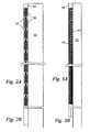
- a first edge device is illustrated in Figures 2A, 2B and 4 .
- the edge device 10 is connected to a front edge of elevator door 12 and has a series of infrared transmitting and/or receiving devices 14 interleaved with a series of illuminable elements generally designated 16.
- the transmitting and/or receiving devices 14 are of the same type as those shown in prior-art Figure 1 .
- the illuminable elements 16 maybe of several types, as will be subsequently more fully described.
- the devices 14 and illuminable elements 16 share a common housing 18 (which can be metal or plastics material). As shown in Figure 4 , the housing 18 is secured to the elevator door 12 by a series of screws 20.
- housing 18 is covered by a cover 22 which is transparent except for a series of rectangular windows 24, textured for diffusing visible light, as shown in Figures 2A ; as also shown in that figure, the infrared devices 14 show through at respective transparent portions of the cover 22.
- the infrared receivers are 'blind' to the light of the coloured diodes because of inbuilt infrared filters, so there is no need to provide a cover screen. However, it may be necessary to separate and shield the illuminable-element circuitry from the infrared device circuitry because of possible interference.
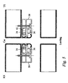
- a second edge device is illustrated in Figures 3A, 3B and 5 .
- the edge device 30 is connected to a front edge of elevator door 32 and has a series of the infrared transmitting and/or receiving devices 34 extending in parallel with a series of the illuminable elements 36.
- the transmitting and/or receiving devices 34 are of the same type as those shown in prior-art Figure 1 .
- the illuminable elements 36 may be of the types that are subsequently more fully described.
- the infrared devices 34 and illuminable elements 36 share a common housing 38 which is approximately twice as wide as the housing 18 of the first embodiment.
- the housing 38 is secured to the elevator door 32 by a series of screws 40.
- the infrared devices 34 and illuminable elements 36 are separated in the housing 38 by a central web 41.
- the front of housing 38 is covered by a cover 42 which is transparent except for a long narrow window 44, textured for diffusing visible light, as shown in Figures 3A .
- a parallel second long narrow window is formed by a continuous infrared device cover 45 (shown in Figure 5 ) that sits behind the transparent cover 42 and forward of a series of the infrared devices 14; the device cover 45 could be formed integral with the series of infrared devices 14 in the housing 38.
- Figures 4 and 5 illustrate the relative position between pairs of elevator doors 12, 32, each carrying an edge device of the invention, and a respective pair of landing doors 26, 46, found on each floor of the building housing the elevator.
- the thickness of the edge devices is such that there is sufficient clearance between the outside of the devices and the surrounding stationary structure of the elevator well that vertical movement of the elevator car is not impeded.
- the RX and TX designations in Figures 4 and 5 are to indicate that all of the infrared receiver devices 14, 34, are on the respective left elevator door while all of the infrared transmitter devices 14, 34, are at respective opposite positions on the respective right elevator door.
- Each elevator door could, however, have both a series of transmitter devices and a series of receiver devices, with the complementary series of receiver devices and transmitter devices being on the other elevator door.
- the external surfaces of the covers 22, 42 can be viewed obliquely, and thus are visible to a person approaching the door from either inside or outside the elevator
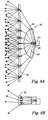
- the first type 36A shown in Figures 5 , 6A and 6B , consists of a lens assembly generally designated 60 that comprises a coloured light-emitting diode (LED) 62 that sits within a cylindrical plastic lens 64 having a parabolic inner section 66 and an elliptical outer section 68.
- a parabolic inner section is used, the inner section could be any conic section that has an eccentricity of unity or greater.
- the plastic diffuser 70 is formed by the respective diffusing windows 24 and 44 described above. As can be seen in figure 6B the diffuser 70 diffuses the light both longitudinally and laterally of the elongate direction of the array.
- the second type 36B of illuminable element 36 shown in Figure 7A and 7B consists of a light-transmitting body in the form of a transparent plastic block 80 having a front face 82 and a reflective back face 84. At least one of the sides of block 80 has a bicolour or tricolour LED mounted thereon for transmitting light such that the light reflects off the back face 84 toward the front face 82.
- the embodiment of Figure 7 has two LEDs 86, 88 mounted on respective angled positions 90, 92 of the ends of the block 80.
- a plastic diffuser 94 sits on the front face 82 of block 80.
- the plastic diffuser 94 may be formed by the diffusing window 24 or 44 of the respective first and second embodiments. It may be possible to dispense with the diffuser 94 if the reflective surface 84 can be sufficiently evenly illuminated by the LED(s), and/or if it is itself capable of scattering light incident upon it.
- the block 80 is effectively a prismatic section, except strictly speaking for its ends which as mentioned above have angled or chamfered portions.
- FIG 8 another form of illuminable element has a light transmitting body 96 in the form of a cylinder of transparent acrylic plastics material (eg.PERSPEX ® ) with red and green LEDs 98, 100 at respective ends thereof.
- the ends of the cylinder body 96 are normal to its longitudinal axis, and the LEDs are disposed with their optical axes directed along the length of the body 96.
- a flat rear surface 102 is provided along the length of the cylinder, eg by grinding or otherwise removing a segment of the cylindrical section. This flat surface is coated with a white reflective material so as to function analogously to the surface 84 of the figure 7 embodiment.
- each illuminable element of the foregoing embodiments are at least able to indicate one or both of the colours green and red.
- the following chart indicates the colours displayed with corresponding actions: Colour Corresponding Action 1. Green glow immediately: Doors start to open; 2. Red glow, after delay: Doors are fully opened; 3. Red glow, after delay: Lift called to another floor; 4. No glow: Doors are fully closed; 5. Flashing, then solid red 'Close Doors' button pushed; 6. Flashes red Door nudging activated.
- Drive circuitry 112 for the LEDs 98,100 operates in response to commands from a controller 114 which also controls door operating gear 116.
- the controller is responsive to user input instructions 118 (e. g. from persons using the elevator), and to feedback from door position sensors 120 and the infrared receivers 14.
- electroluminescent plastic wires may be used. Such materials give out a rather dim light at present, but their light output is improving steadily.
- a binary or multi-element strip or wire of such plastic could be run alongside the infrared detector assembly and would not require the use of the diffuser previously mentioned.
- Various colours would be providing by activating one, or several, strips as necessary.
- Electroluminescent plastic wires would also allow complex shapes and multicolour patterns of light emission to be created.
- the wires are formed as coaxial cable, with phosphor (for example, ZnS) in the cylindrical region separating the two conductors of the cable.
- Figure 9 illustrates a simple example of such a device.
- Two strips 104, 106 of electroluminescent material (one green, one red) are provided, each driven by a respective oscillator 108, 110 as known per se.
- a separate diffuser element may not be necessary and the strips can be mounted directly in the channel sections of figures 4 and 5 , on supports so that they form a flush edge in the same way as do the diffuser elements illustrated therein.
- the control arrangements for this embodiment correspond to those of figure 8 .
- illuminable element lend themselves to arrangement as a elongate array with the elements substantially end-to-end, perhaps separated by the infrared elements in the inter leaved embodiment of figure 2 .
- the elements may abut end to end (in the case of figure 6 it is the diffuser elements 70 which will abut) or they maybe separated by the structure supporting the LEDs.
- the figure 9 embodiment is suitable for the installation of figure 2 . It may alternatively be arranged as a single line of alternately red and green strips end-to-end which would lend itself to the structure of figure 3 . Substantially end to end thus is to be interpreted to include the interposition of some relatively short structure between the elongate illuminable elements.
- An edge device for an elevator door includes an elongate array of infrared transmitters and/or receivers and a proximate elongate array of illuminable elements, both arrays extending for a substantial part of the length of the door.
- the illuminable elements are adapted to be illuminated when the door is in motion.
- the two arrays are disposed in a common carrier structure, being either vertically interleaved or extending vertically in parallel with each other.
Landscapes
- Elevator Door Apparatuses (AREA)
- Power-Operated Mechanisms For Wings (AREA)
- Cage And Drive Apparatuses For Elevators (AREA)
- Automobile Manufacture Line, Endless Track Vehicle, Trailer (AREA)
- Chain Conveyers (AREA)
- Control Or Security For Electrophotography (AREA)
Claims (10)
- Beleuchtbares Element für eine Kantenvorrichtung einer kraftangetriebenen Tür eines Aufzugeingangs, wobei das beleuchtbare Element:eine längliche Dimension aufweist;so konfiguriert ist, dass es im Wesentlichen Ende-an-Ende mit anderen derartigen Elementen in der Kantenvorrichtung angeordnet ist;Folgendes umfasst: mindestens eine lokalisierte Quelle von sichtbarem Licht (86, 88, 98, 100) und eine Lichtaustrittsfläche, die entlang der länglichen Dimension angeordnet ist, wobei die mindestens eine lokalisierte Quelle von sichtbarem Licht (86, 88, 98, 100) Folgendes umfasst: eine erste lokalisierte Lichtquelle (86, 98) und eine zweite lokalisierte Lichtquelle (86, 98), und ferner Folgendes umfasst:einen länglichen Lichtübertragungskörper (80, 96), der eine reflektierende Fläche (84, 102) aufweist, wobei jede Lichtquelle (86, 88, 98, 100) so angeordnet ist, dass sie Licht in Richtung der reflektierenden Fläche (84, 102) richtet, wobei das Licht, das davon reflektiert wird, aus dem Lichtübertragungselement über die Lichtaustrittsfläche austritt, die eine weitere Fläche des länglichen Lichtübertragungskörpers (80, 96) bildet; undwobei die erste und zweite lokalisierte Lichtquelle (86, 88, 98, 100) jeweils Folgendes umfasst: eine Leuchtdiode, die dafür ausgelegt ist, Licht von einer jeweiligen Farbe zu emittieren, die sich von dem Licht, das von der jeweils anderen der ersten und zweiten lokalisierten Lichtquelle (86, 88, 98, 100) emittiert wird, unterscheidet, wodurch jede jeweilige unterschiedliche Farbe des sichtbaren Lichts von der länglichen Lichtaustrittsfläche emittiert wird.
- Beleuchtbares Element nach Anspruch 1, das ferner einen Diffusor (94) zum Streuen von Licht umfasst, das über die weitere Fläche austritt.
- Beleuchtbares Element nach Anspruch 1 oder 2, wobei jede Lichtquelle (86, 88, 98, 100) an einem jeweiligen Ende des Lichtübertragungskörpers angeordnet ist.
- Beleuchtbares Element nach Anspruch 3, wobei eine optische Achse jeder Lichtquelle (86, 88, 98, 100) entlang der Achse der Ausdehnung des Lichtübertragungskörpers (96) gerichtet ist, so dass sie auf die reflektierende Oberfläche (84, 102) auftrifft.
- Beleuchtbares Element nach Anspruch 3, wobei eine optische Achse jeder Lichtquelle (86, 88, 98, 100) in einem spitzen Winkel zur der Achse der Ausdehnung des Lichtübertragungskörpers (80) gerichtet ist, so dass sie auf die reflektierende Oberfläche (84, 102) auftrifft.
- Beleuchtbares Element nach einem der vorhergehenden Ansprüche, wobei der Lichtübertragungskörper (96) einen im Allgemeinen zylindrischen Abschnitt aufweist, wobei die reflektierende Fläche (102) ein Abschnitt einer Umfangsfläche davon ist.
- Beleuchtbares Element nach Anspruch 6, wobei die reflektierende Fläche ein abgeflachter Abschnitt der Umfangsfläche ist.
- Beleuchtbares Element nach einem der Ansprüche 1 bis 5, wobei, mit Ausnahme der Enden davon, der Lichtübertragungskörper (80) im Allgemeinen einen prismatischen Querschnitt aufweist.
- Sicherheitssensorvorrichtung für einen Aufzugseingang, der mindestens eine kraftangetriebene Aufzugtür aufweist, wobei die Sicherheitssensorvorrichtung ein Erfassungssystem umfasst, das eine längliche Anordnung von Infrarot-Senderelementen und/oder Infrarot-Empfängerelementen umfasst, die dafür ausgelegt ist, Objekte zu erfassen, die sich nahe des Aufzugeingangs befinden, wenn die Aufzugtür offen ist, und mindestens ein beleuchtbares Element nach einem der vorhergehenden Ansprüche umfasst.
- Aufzugeingang, der mindestens eine Aufzugtür und eine Sicherheitssensorvorrichtung nach Anspruch 9 aufweist.
Applications Claiming Priority (2)
| Application Number | Priority Date | Filing Date | Title |
|---|---|---|---|
| GB0309310A GB2400905A (en) | 2003-04-24 | 2003-04-24 | Edge device for a powered door with infra-red and visible elements |
| EP04729466A EP1626924B1 (de) | 2003-04-24 | 2004-04-26 | Multifunktionskantenvorrichtung für kraftangetriebene türen |
Related Parent Applications (2)
| Application Number | Title | Priority Date | Filing Date |
|---|---|---|---|
| EP04729466.5 Division | 2004-04-26 | ||
| EP04729466A Division EP1626924B1 (de) | 2003-04-24 | 2004-04-26 | Multifunktionskantenvorrichtung für kraftangetriebene türen |
Publications (2)
| Publication Number | Publication Date |
|---|---|
| EP2292548A1 EP2292548A1 (de) | 2011-03-09 |
| EP2292548B1 true EP2292548B1 (de) | 2014-06-18 |
Family
ID=33042171
Family Applications (2)
| Application Number | Title | Priority Date | Filing Date |
|---|---|---|---|
| EP10180314.6A Expired - Lifetime EP2292548B1 (de) | 2003-04-24 | 2004-04-26 | Mehrzweckkantenvorrichtung für angetriebene Türen |
| EP04729466A Expired - Lifetime EP1626924B1 (de) | 2003-04-24 | 2004-04-26 | Multifunktionskantenvorrichtung für kraftangetriebene türen |
Family Applications After (1)
| Application Number | Title | Priority Date | Filing Date |
|---|---|---|---|
| EP04729466A Expired - Lifetime EP1626924B1 (de) | 2003-04-24 | 2004-04-26 | Multifunktionskantenvorrichtung für kraftangetriebene türen |
Country Status (11)
| Country | Link |
|---|---|
| US (2) | US7771080B2 (de) |
| EP (2) | EP2292548B1 (de) |
| AT (1) | ATE484478T1 (de) |
| AU (2) | AU2004232541B2 (de) |
| CA (1) | CA2523362C (de) |
| DE (1) | DE602004029567D1 (de) |
| DK (1) | DK1626924T3 (de) |
| ES (1) | ES2350342T3 (de) |
| GB (1) | GB2400905A (de) |
| PT (1) | PT1626924E (de) |
| WO (1) | WO2004094290A2 (de) |
Families Citing this family (20)
| Publication number | Priority date | Publication date | Assignee | Title |
|---|---|---|---|---|
| US8225458B1 (en) | 2001-07-13 | 2012-07-24 | Hoffberg Steven M | Intelligent door restraint |
| GB2420176B (en) | 2004-11-15 | 2009-11-04 | Memco Ltd | Safety sensing system for a powered door system |
| DE102005001317A1 (de) * | 2005-01-11 | 2006-07-20 | Dorma Gmbh + Co. Kg | Anzeigevorrichtung für den Antrieb einer Drehtür, Schiebetür oder dergleichen |
| GB2438422B (en) * | 2006-05-22 | 2009-09-23 | Memco Ltd | Obstacle-detecting apparatus for a powered door system |
| TWI402207B (zh) * | 2008-09-01 | 2013-07-21 | Fujitec Kk | 電梯的安全裝置 |
| CN102159488B (zh) * | 2008-12-26 | 2014-06-25 | 三菱电机株式会社 | 滑动门装置及电梯 |
| DE102010004116A1 (de) | 2010-01-07 | 2011-07-14 | TÜV NORD Sys Tec GmbH & Co. KG, 22525 | Durchgang für ein Fahrzeug, eine Kabine oder dergleichen |
| DE102010026140A1 (de) * | 2010-07-05 | 2012-01-05 | Cedes Ag | Überwachungsvorrichtung zur Absicherung eines angetriebenen Elements |
| DE102011002054A1 (de) | 2011-04-14 | 2012-10-18 | Dorma Gmbh & Co Kg | Flügelanlage |
| US20130009785A1 (en) * | 2011-07-07 | 2013-01-10 | Finn Clayton L | Visual and Audio Warning System Including Test Ledger for Automated Door |
| US20130086841A1 (en) * | 2011-10-10 | 2013-04-11 | William M. Luper | Overhead Door Object Detection Apparatus |
| EP2789564B1 (de) * | 2013-04-12 | 2020-09-16 | KONE Corporation | Befestigungsvorrichtung für ein Lichtgitter in einem Aufzug |
| US12404714B2 (en) | 2015-09-14 | 2025-09-02 | Rytec Corporation | System and method for safety management in roll-up doors |
| US10619397B2 (en) | 2015-09-14 | 2020-04-14 | Rytec Corporation | System and method for safety management in roll-up doors |
| GB201814019D0 (en) | 2018-08-29 | 2018-10-10 | Avire Ltd | An elevator door sensor controller |
| EP3899186A4 (de) | 2018-12-21 | 2022-10-05 | Rytec Corporation | Sicherheitssystem und -verfahren für rolltore |
| US11941858B2 (en) | 2020-01-23 | 2024-03-26 | Nec Corporation | Object recognition device |
| JPWO2021149219A1 (de) * | 2020-01-23 | 2021-07-29 | ||
| GB2633103A (en) * | 2023-09-01 | 2025-03-05 | Avire Ltd | Elevator safety system |
| DE102024117581A1 (de) | 2024-06-21 | 2025-12-24 | Cedes Ag | Optische Überwachungsvorrichtung zur Interaktion mit Benutzern |
Family Cites Families (41)
| Publication number | Priority date | Publication date | Assignee | Title |
|---|---|---|---|---|
| JPS48102585A (de) * | 1972-04-04 | 1973-12-22 | ||
| US4794248A (en) * | 1985-07-16 | 1988-12-27 | Otis Elevator Company | Detection device having energy transmitters located at vertically spaced apart points along movable doors |
| JPS59204815A (ja) * | 1983-05-09 | 1984-11-20 | Yamagata Daigaku | 照明用照度平均化レンズ |
| JPH0129928Y2 (de) * | 1984-09-29 | 1989-09-12 | ||
| JPH07104492B2 (ja) * | 1985-12-28 | 1995-11-13 | オリンパス光学工業株式会社 | 内視鏡用照明光学系 |
| US4954931A (en) * | 1988-07-08 | 1990-09-04 | Parker Hannifin Corporation | Linear diffuse light source |
| US5142152A (en) * | 1991-01-02 | 1992-08-25 | The Stanley Works | Sliding door sensor |
| US5161879A (en) * | 1991-04-10 | 1992-11-10 | Mcdermott Kevin | Flashlight for covert applications |
| GB2254916B (en) * | 1991-04-15 | 1993-12-22 | John Trett | Detection systems |
| US5149921A (en) * | 1991-07-10 | 1992-09-22 | Innovation Industries, Inc. | Self correcting infrared intrusion detection system |
| US5325271A (en) * | 1992-06-10 | 1994-06-28 | Dominion Automotive Industries Corp. | Marker lamp with LED array and prismatic diffuser |
| US5607227A (en) * | 1993-08-27 | 1997-03-04 | Sanyo Electric Co., Ltd. | Linear light source |
| JPH07137970A (ja) * | 1993-11-16 | 1995-05-30 | Mitsubishi Denki Bill Techno Service Kk | エレベーター扉の安全装置 |
| JPH07309568A (ja) * | 1994-05-17 | 1995-11-28 | Hitachi Building Syst Eng & Service Co Ltd | 自動開閉ドアの安全装置 |
| US5526190A (en) * | 1994-09-29 | 1996-06-11 | Xerox Corporation | Optical element and device for providing uniform irradiance of a surface |
| JPH08159871A (ja) * | 1994-12-04 | 1996-06-21 | Horiba Ltd | 焦電型赤外線検出器 |
| JPH08259156A (ja) * | 1995-03-24 | 1996-10-08 | Otis Elevator Co | エレベーター |
| DE19536451A1 (de) * | 1995-09-29 | 1997-04-10 | Siemens Ag | Infrarotsender |
| US5971570A (en) * | 1995-11-13 | 1999-10-26 | Simon; Jerome H. | Decorative prismatic lens jacket for a lineal source |
| US5803579A (en) * | 1996-06-13 | 1998-09-08 | Gentex Corporation | Illuminator assembly incorporating light emitting diodes |
| JPH1087243A (ja) * | 1996-09-11 | 1998-04-07 | Hitachi Ltd | エレベータ扉の安全装置 |
| CN1123874C (zh) * | 1997-05-07 | 2003-10-08 | 索尼株式会社 | 光拾取装置 |
| US6031958A (en) * | 1997-05-21 | 2000-02-29 | Mcgaffigan; Thomas H. | Optical light pipes with laser light appearance |
| JP3822961B2 (ja) * | 1997-09-11 | 2006-09-20 | 大日本印刷株式会社 | レンチキュラーレンズシート及び透過型スクリーン |
| US6169333B1 (en) * | 1997-10-06 | 2001-01-02 | Visteon Global Technologies, Inc. | Starter motor drive stop |
| FR2776595B1 (fr) * | 1998-03-31 | 2000-06-16 | Valeo Vision | Feu de signalisation comprenant plusieurs sources lumineuses |
| JPH11335043A (ja) * | 1998-05-21 | 1999-12-07 | Hitachi Building Systems Co Ltd | エレベータドアの安全装置 |
| US6266476B1 (en) * | 1998-08-25 | 2001-07-24 | Physical Optics Corporation | Optical element having an integral surface diffuser |
| ATE253761T1 (de) * | 1998-09-04 | 2003-11-15 | Wynne Willson Gottelier Ltd | Vorrichtung und verfahren zur bereitstellung eines linearen effekts |
| JP3372887B2 (ja) * | 1999-02-19 | 2003-02-04 | 株式会社日立ビルシステム | エレベータ出入口の安全装置 |
| IT1308286B1 (it) * | 1999-06-15 | 2001-12-10 | Leonardo Masotti | Sorgenti e ricevitori ottici estesi continui e barriere otticheutilizzanti dette sorgenti e detti ricevitori |
| FR2813379B1 (fr) * | 2000-08-28 | 2002-11-29 | Valeo Vision | Feu de signalisation a structure optique simplifiee |
| ITTO20010461A1 (it) * | 2001-05-18 | 2002-11-18 | Fiat Ricerche | Dispositivo di illuminazione, particolarmente fanale per autoveicoli o luce di emergenza. |
| DE10137605A1 (de) * | 2001-08-01 | 2003-02-27 | Hella Kg Hueck & Co | Leuchte für Fahrzeuge |
| JP4208535B2 (ja) * | 2001-12-12 | 2009-01-14 | 株式会社キーエンス | 多光軸光電センサ及びその取付具 |
| US6871993B2 (en) * | 2002-07-01 | 2005-03-29 | Accu-Sort Systems, Inc. | Integrating LED illumination system for machine vision systems |
| US7625097B2 (en) * | 2002-09-06 | 2009-12-01 | Toshiba Elevator Kabushiki Kaisha | Illuminated elevator including cold-cathode flourescent lamp |
| US20040075548A1 (en) * | 2002-10-21 | 2004-04-22 | Beggs Ryan P. | Monitoring a remote body detection system of a door |
| EP1592176B1 (de) * | 2003-02-03 | 2017-04-12 | Sony Corporation | Kommunikationsverfahren, kommunikationseinrichtung und computerprogramm |
| US6923554B2 (en) * | 2003-02-17 | 2005-08-02 | Heng Sheng Kuo | Backlight module |
| CN101941668B (zh) * | 2003-03-21 | 2013-01-02 | 约瑟夫·坎弗 | 无需用手致动的用于分配一定量物质的装置 |
-
2003
- 2003-04-24 GB GB0309310A patent/GB2400905A/en not_active Withdrawn
-
2004
- 2004-04-26 ES ES04729466T patent/ES2350342T3/es not_active Expired - Lifetime
- 2004-04-26 CA CA2523362A patent/CA2523362C/en not_active Expired - Lifetime
- 2004-04-26 AT AT04729466T patent/ATE484478T1/de active
- 2004-04-26 DK DK04729466.5T patent/DK1626924T3/da active
- 2004-04-26 PT PT04729466T patent/PT1626924E/pt unknown
- 2004-04-26 WO PCT/GB2004/001764 patent/WO2004094290A2/en not_active Ceased
- 2004-04-26 US US10/553,934 patent/US7771080B2/en not_active Expired - Lifetime
- 2004-04-26 DE DE602004029567T patent/DE602004029567D1/de not_active Expired - Lifetime
- 2004-04-26 AU AU2004232541A patent/AU2004232541B2/en not_active Expired
- 2004-04-26 EP EP10180314.6A patent/EP2292548B1/de not_active Expired - Lifetime
- 2004-04-26 EP EP04729466A patent/EP1626924B1/de not_active Expired - Lifetime
-
2010
- 2010-02-26 AU AU2010200734A patent/AU2010200734B2/en not_active Expired
- 2010-06-22 US US12/820,558 patent/US20100308222A1/en not_active Abandoned
Also Published As
| Publication number | Publication date |
|---|---|
| US7771080B2 (en) | 2010-08-10 |
| US20100308222A1 (en) | 2010-12-09 |
| AU2010200734B2 (en) | 2012-04-26 |
| ATE484478T1 (de) | 2010-10-15 |
| GB2400905A (en) | 2004-10-27 |
| ES2350342T3 (es) | 2011-01-21 |
| CA2523362A1 (en) | 2004-11-04 |
| EP2292548A1 (de) | 2011-03-09 |
| DE602004029567D1 (de) | 2010-11-25 |
| EP1626924A2 (de) | 2006-02-22 |
| WO2004094290A3 (en) | 2005-02-10 |
| AU2010200734A1 (en) | 2010-03-18 |
| AU2004232541A1 (en) | 2004-11-04 |
| EP1626924B1 (de) | 2010-10-13 |
| CA2523362C (en) | 2012-07-17 |
| AU2004232541B2 (en) | 2009-11-26 |
| DK1626924T3 (da) | 2011-01-10 |
| WO2004094290A2 (en) | 2004-11-04 |
| US20070064424A1 (en) | 2007-03-22 |
| PT1626924E (pt) | 2011-01-20 |
Similar Documents
| Publication | Publication Date | Title |
|---|---|---|
| US20100308222A1 (en) | Multifunction Edge Device for Powered Doors | |
| US11434687B2 (en) | Profiled safety strip and door comprising a profiled safety strip | |
| US11110854B2 (en) | Vehicle door handle assembly with light sensing module | |
| CN111994037A (zh) | 使用投射图标的车辆功能控制系统 | |
| KR102027638B1 (ko) | 초전형(pir) 움직임 감지센서를 이용한 안전센서 및 이를 이용한 자동문 시스템 | |
| US20160347240A1 (en) | Running board illumination system and method for a motor vehicle | |
| US20170190282A1 (en) | Running board illumination system and method for a motor vehicle | |
| US5627439A (en) | Light barrier for reopening elevator doors | |
| WO2007135371A1 (en) | Obstacle-detecting apparatus for a powered door system | |
| AU2012207023B2 (en) | Multifunction edge device for powered doors | |
| GB2453804A (en) | Sensing obstacles in front and to the front sides of sliding powered doors | |
| EP3286125B1 (de) | Aufzugsystem und verfahren zur adaption eines aufzugssystems | |
| CN104126094A (zh) | 用于自动扶梯、移动步道或升降梯轿厢的能够被照亮的嵌板 | |
| CN113882785A (zh) | 具有光信号功能的旋转门 | |
| CN105984797A (zh) | 乘客输送机 | |
| KR102129841B1 (ko) | 독거노인을 위한 응급안전 센서등 | |
| JP5211935B2 (ja) | スライドドア装置 | |
| KR100913469B1 (ko) | 유리 도어를 구비한 엘리베이터 카의 도어와 인접 벽 사이의 외부 물체 특히 손가락을 검출하는 장치, 및 이 검출 장치를 장착한 엘리베이터 | |
| KR20240016749A (ko) | 차량의 실내 조명 장치 및 이를 포함한 조명 제어 시스템 | |
| CN119953987A (zh) | 电梯的厅门灯和电梯系统 | |
| MXPA97005097A (en) | Barrier of light to re-open doors of ascent |
Legal Events
| Date | Code | Title | Description |
|---|---|---|---|
| PUAI | Public reference made under article 153(3) epc to a published international application that has entered the european phase |
Free format text: ORIGINAL CODE: 0009012 |
|
| AC | Divisional application: reference to earlier application |
Ref document number: 1626924 Country of ref document: EP Kind code of ref document: P |
|
| AK | Designated contracting states |
Kind code of ref document: A1 Designated state(s): AT BE BG CH CY CZ DE DK EE ES FI FR GB GR HU IE IT LI LU MC NL PL PT RO SE SI SK TR |
|
| 17P | Request for examination filed |
Effective date: 20110909 |
|
| 17Q | First examination report despatched |
Effective date: 20120430 |
|
| GRAP | Despatch of communication of intention to grant a patent |
Free format text: ORIGINAL CODE: EPIDOSNIGR1 |
|
| INTG | Intention to grant announced |
Effective date: 20140108 |
|
| RAP1 | Party data changed (applicant data changed or rights of an application transferred) |
Owner name: AVIRE LIMITED |
|
| GRAS | Grant fee paid |
Free format text: ORIGINAL CODE: EPIDOSNIGR3 |
|
| GRAA | (expected) grant |
Free format text: ORIGINAL CODE: 0009210 |
|
| AC | Divisional application: reference to earlier application |
Ref document number: 1626924 Country of ref document: EP Kind code of ref document: P |
|
| AK | Designated contracting states |
Kind code of ref document: B1 Designated state(s): AT BE BG CH CY CZ DE DK EE ES FI FR GB GR HU IE IT LI LU MC NL PL PT RO SE SI SK TR |
|
| REG | Reference to a national code |
Ref country code: GB Ref legal event code: FG4D |
|
| REG | Reference to a national code |
Ref country code: CH Ref legal event code: EP |
|
| REG | Reference to a national code |
Ref country code: AT Ref legal event code: REF Ref document number: 673217 Country of ref document: AT Kind code of ref document: T Effective date: 20140715 Ref country code: CH Ref legal event code: NV Representative=s name: SERVOPATENT GMBH, CH |
|
| REG | Reference to a national code |
Ref country code: IE Ref legal event code: FG4D |
|
| REG | Reference to a national code |
Ref country code: DE Ref legal event code: R096 Ref document number: 602004045314 Country of ref document: DE Effective date: 20140731 |
|
| REG | Reference to a national code |
Ref country code: SE Ref legal event code: TRGR |
|
| PG25 | Lapsed in a contracting state [announced via postgrant information from national office to epo] |
Ref country code: FI Free format text: LAPSE BECAUSE OF FAILURE TO SUBMIT A TRANSLATION OF THE DESCRIPTION OR TO PAY THE FEE WITHIN THE PRESCRIBED TIME-LIMIT Effective date: 20140618 Ref country code: CY Free format text: LAPSE BECAUSE OF FAILURE TO SUBMIT A TRANSLATION OF THE DESCRIPTION OR TO PAY THE FEE WITHIN THE PRESCRIBED TIME-LIMIT Effective date: 20140618 Ref country code: GR Free format text: LAPSE BECAUSE OF FAILURE TO SUBMIT A TRANSLATION OF THE DESCRIPTION OR TO PAY THE FEE WITHIN THE PRESCRIBED TIME-LIMIT Effective date: 20140919 |
|
| REG | Reference to a national code |
Ref country code: NL Ref legal event code: VDEP Effective date: 20140618 |
|
| REG | Reference to a national code |
Ref country code: AT Ref legal event code: MK05 Ref document number: 673217 Country of ref document: AT Kind code of ref document: T Effective date: 20140618 |
|
| PG25 | Lapsed in a contracting state [announced via postgrant information from national office to epo] |
Ref country code: CZ Free format text: LAPSE BECAUSE OF FAILURE TO SUBMIT A TRANSLATION OF THE DESCRIPTION OR TO PAY THE FEE WITHIN THE PRESCRIBED TIME-LIMIT Effective date: 20140618 Ref country code: EE Free format text: LAPSE BECAUSE OF FAILURE TO SUBMIT A TRANSLATION OF THE DESCRIPTION OR TO PAY THE FEE WITHIN THE PRESCRIBED TIME-LIMIT Effective date: 20140618 Ref country code: PT Free format text: LAPSE BECAUSE OF FAILURE TO SUBMIT A TRANSLATION OF THE DESCRIPTION OR TO PAY THE FEE WITHIN THE PRESCRIBED TIME-LIMIT Effective date: 20141020 Ref country code: SK Free format text: LAPSE BECAUSE OF FAILURE TO SUBMIT A TRANSLATION OF THE DESCRIPTION OR TO PAY THE FEE WITHIN THE PRESCRIBED TIME-LIMIT Effective date: 20140618 Ref country code: ES Free format text: LAPSE BECAUSE OF FAILURE TO SUBMIT A TRANSLATION OF THE DESCRIPTION OR TO PAY THE FEE WITHIN THE PRESCRIBED TIME-LIMIT Effective date: 20140618 Ref country code: RO Free format text: LAPSE BECAUSE OF FAILURE TO SUBMIT A TRANSLATION OF THE DESCRIPTION OR TO PAY THE FEE WITHIN THE PRESCRIBED TIME-LIMIT Effective date: 20140618 |
|
| PG25 | Lapsed in a contracting state [announced via postgrant information from national office to epo] |
Ref country code: PL Free format text: LAPSE BECAUSE OF FAILURE TO SUBMIT A TRANSLATION OF THE DESCRIPTION OR TO PAY THE FEE WITHIN THE PRESCRIBED TIME-LIMIT Effective date: 20140618 Ref country code: NL Free format text: LAPSE BECAUSE OF FAILURE TO SUBMIT A TRANSLATION OF THE DESCRIPTION OR TO PAY THE FEE WITHIN THE PRESCRIBED TIME-LIMIT Effective date: 20140618 Ref country code: AT Free format text: LAPSE BECAUSE OF FAILURE TO SUBMIT A TRANSLATION OF THE DESCRIPTION OR TO PAY THE FEE WITHIN THE PRESCRIBED TIME-LIMIT Effective date: 20140618 |
|
| REG | Reference to a national code |
Ref country code: DE Ref legal event code: R097 Ref document number: 602004045314 Country of ref document: DE |
|
| PLBE | No opposition filed within time limit |
Free format text: ORIGINAL CODE: 0009261 |
|
| STAA | Information on the status of an ep patent application or granted ep patent |
Free format text: STATUS: NO OPPOSITION FILED WITHIN TIME LIMIT |
|
| REG | Reference to a national code |
Ref country code: FR Ref legal event code: PLFP Year of fee payment: 12 |
|
| PG25 | Lapsed in a contracting state [announced via postgrant information from national office to epo] |
Ref country code: DK Free format text: LAPSE BECAUSE OF FAILURE TO SUBMIT A TRANSLATION OF THE DESCRIPTION OR TO PAY THE FEE WITHIN THE PRESCRIBED TIME-LIMIT Effective date: 20140618 |
|
| 26N | No opposition filed |
Effective date: 20150319 |
|
| PG25 | Lapsed in a contracting state [announced via postgrant information from national office to epo] |
Ref country code: BE Free format text: LAPSE BECAUSE OF FAILURE TO SUBMIT A TRANSLATION OF THE DESCRIPTION OR TO PAY THE FEE WITHIN THE PRESCRIBED TIME-LIMIT Effective date: 20140618 |
|
| PG25 | Lapsed in a contracting state [announced via postgrant information from national office to epo] |
Ref country code: SI Free format text: LAPSE BECAUSE OF FAILURE TO SUBMIT A TRANSLATION OF THE DESCRIPTION OR TO PAY THE FEE WITHIN THE PRESCRIBED TIME-LIMIT Effective date: 20140618 |
|
| PG25 | Lapsed in a contracting state [announced via postgrant information from national office to epo] |
Ref country code: LU Free format text: LAPSE BECAUSE OF FAILURE TO SUBMIT A TRANSLATION OF THE DESCRIPTION OR TO PAY THE FEE WITHIN THE PRESCRIBED TIME-LIMIT Effective date: 20150426 Ref country code: MC Free format text: LAPSE BECAUSE OF FAILURE TO SUBMIT A TRANSLATION OF THE DESCRIPTION OR TO PAY THE FEE WITHIN THE PRESCRIBED TIME-LIMIT Effective date: 20140618 |
|
| REG | Reference to a national code |
Ref country code: FR Ref legal event code: PLFP Year of fee payment: 13 |
|
| REG | Reference to a national code |
Ref country code: FR Ref legal event code: PLFP Year of fee payment: 14 |
|
| PG25 | Lapsed in a contracting state [announced via postgrant information from national office to epo] |
Ref country code: BG Free format text: LAPSE BECAUSE OF FAILURE TO SUBMIT A TRANSLATION OF THE DESCRIPTION OR TO PAY THE FEE WITHIN THE PRESCRIBED TIME-LIMIT Effective date: 20140618 Ref country code: HU Free format text: LAPSE BECAUSE OF FAILURE TO SUBMIT A TRANSLATION OF THE DESCRIPTION OR TO PAY THE FEE WITHIN THE PRESCRIBED TIME-LIMIT; INVALID AB INITIO Effective date: 20040426 |
|
| PG25 | Lapsed in a contracting state [announced via postgrant information from national office to epo] |
Ref country code: TR Free format text: LAPSE BECAUSE OF FAILURE TO SUBMIT A TRANSLATION OF THE DESCRIPTION OR TO PAY THE FEE WITHIN THE PRESCRIBED TIME-LIMIT Effective date: 20140618 |
|
| REG | Reference to a national code |
Ref country code: FR Ref legal event code: PLFP Year of fee payment: 15 |
|
| REG | Reference to a national code |
Ref country code: CH Ref legal event code: PCAR Free format text: NEW ADDRESS: WANNERSTRASSE 9/1, 8045 ZUERICH (CH) |
|
| PGFP | Annual fee paid to national office [announced via postgrant information from national office to epo] |
Ref country code: GB Payment date: 20230212 Year of fee payment: 20 |
|
| P01 | Opt-out of the competence of the unified patent court (upc) registered |
Effective date: 20230607 |
|
| P02 | Opt-out of the competence of the unified patent court (upc) changed |
Effective date: 20230621 |
|
| PGFP | Annual fee paid to national office [announced via postgrant information from national office to epo] |
Ref country code: IT Payment date: 20230421 Year of fee payment: 20 Ref country code: IE Payment date: 20230419 Year of fee payment: 20 Ref country code: FR Payment date: 20230425 Year of fee payment: 20 Ref country code: DE Payment date: 20230420 Year of fee payment: 20 Ref country code: CH Payment date: 20230502 Year of fee payment: 20 |
|
| PGFP | Annual fee paid to national office [announced via postgrant information from national office to epo] |
Ref country code: SE Payment date: 20230420 Year of fee payment: 20 |
|
| REG | Reference to a national code |
Ref country code: DE Ref legal event code: R071 Ref document number: 602004045314 Country of ref document: DE |
|
| REG | Reference to a national code |
Ref country code: CH Ref legal event code: PL |
|
| REG | Reference to a national code |
Ref country code: GB Ref legal event code: PE20 Expiry date: 20240425 |
|
| REG | Reference to a national code |
Ref country code: SE Ref legal event code: EUG |
|
| REG | Reference to a national code |
Ref country code: IE Ref legal event code: MK9A |
|
| PG25 | Lapsed in a contracting state [announced via postgrant information from national office to epo] |
Ref country code: IE Free format text: LAPSE BECAUSE OF EXPIRATION OF PROTECTION Effective date: 20240426 |
|
| PG25 | Lapsed in a contracting state [announced via postgrant information from national office to epo] |
Ref country code: GB Free format text: LAPSE BECAUSE OF EXPIRATION OF PROTECTION Effective date: 20240425 |
|
| PG25 | Lapsed in a contracting state [announced via postgrant information from national office to epo] |
Ref country code: IE Free format text: LAPSE BECAUSE OF EXPIRATION OF PROTECTION Effective date: 20240426 Ref country code: GB Free format text: LAPSE BECAUSE OF EXPIRATION OF PROTECTION Effective date: 20240425 |