EP3286125B1 - Aufzugsystem und verfahren zur adaption eines aufzugssystems - Google Patents
Aufzugsystem und verfahren zur adaption eines aufzugssystems Download PDFInfo
- Publication number
- EP3286125B1 EP3286125B1 EP16713007.9A EP16713007A EP3286125B1 EP 3286125 B1 EP3286125 B1 EP 3286125B1 EP 16713007 A EP16713007 A EP 16713007A EP 3286125 B1 EP3286125 B1 EP 3286125B1
- Authority
- EP
- European Patent Office
- Prior art keywords
- lift car
- luminaire
- landing
- toe guard
- floor
- Prior art date
- Legal status (The legal status is an assumption and is not a legal conclusion. Google has not performed a legal analysis and makes no representation as to the accuracy of the status listed.)
- Active
Links
Images


Classifications
-
- B—PERFORMING OPERATIONS; TRANSPORTING
- B66—HOISTING; LIFTING; HAULING
- B66B—ELEVATORS; ESCALATORS OR MOVING WALKWAYS
- B66B13/00—Doors, gates, or other apparatus controlling access to, or exit from, cages or lift well landings
- B66B13/24—Safety devices in passenger lifts, not otherwise provided for, for preventing trapping of passengers
- B66B13/28—Safety devices in passenger lifts, not otherwise provided for, for preventing trapping of passengers between car or cage and wells
- B66B13/285—Toe guards or apron devices
-
- B—PERFORMING OPERATIONS; TRANSPORTING
- B66—HOISTING; LIFTING; HAULING
- B66B—ELEVATORS; ESCALATORS OR MOVING WALKWAYS
- B66B13/00—Doors, gates, or other apparatus controlling access to, or exit from, cages or lift well landings
- B66B13/24—Safety devices in passenger lifts, not otherwise provided for, for preventing trapping of passengers
- B66B13/28—Safety devices in passenger lifts, not otherwise provided for, for preventing trapping of passengers between car or cage and wells
-
- B—PERFORMING OPERATIONS; TRANSPORTING
- B66—HOISTING; LIFTING; HAULING
- B66B—ELEVATORS; ESCALATORS OR MOVING WALKWAYS
- B66B13/00—Doors, gates, or other apparatus controlling access to, or exit from, cages or lift well landings
- B66B13/30—Constructional features of doors or gates
- B66B13/301—Details of door sills
-
- B—PERFORMING OPERATIONS; TRANSPORTING
- B66—HOISTING; LIFTING; HAULING
- B66B—ELEVATORS; ESCALATORS OR MOVING WALKWAYS
- B66B19/00—Mining-hoist operation
- B66B19/007—Mining-hoist operation method for modernisation of elevators
-
- B—PERFORMING OPERATIONS; TRANSPORTING
- B66—HOISTING; LIFTING; HAULING
- B66B—ELEVATORS; ESCALATORS OR MOVING WALKWAYS
- B66B3/00—Applications of devices for indicating or signalling operating conditions of elevators
- B66B3/002—Indicators
-
- B—PERFORMING OPERATIONS; TRANSPORTING
- B66—HOISTING; LIFTING; HAULING
- B66B—ELEVATORS; ESCALATORS OR MOVING WALKWAYS
- B66B5/00—Applications of checking, fault-correcting, or safety devices in elevators
- B66B5/02—Applications of checking, fault-correcting, or safety devices in elevators responsive to abnormal operating conditions
Definitions
- the present invention relates to a method of adapting an elevator system and to an elevator system that has been adapted according to the invention.
- Lift cars used in elevator systems to convey passengers between floors of a building are designed to stop to within ⁇ 2 millimetres of a destination floor landing. This is to limit the size of the step that exists between the lift car floor and the landing. However, precise stopping of a lift car is not always achieved and this can present a trip hazard for passengers entering and exiting the lift car.
- the method may comprise positioning the luminaire at a distance below said edge of the lift car floor by a distance which is greater than said maximum accepted level of misalignment.
- the method may include the step of mounting the LED strip light to the wall.
- an elevator system comprising a lift car, the system being adapted to warn elevator users of the existence of a vertical misalignment between a floor of the lift car and a landing surface adjacent to which the lift car stops, and where there is a gap between facing parallel walls depending vertically downwards from a leading edge of the lift car floor and a leading edge of the landing surface, respectively, the system including a luminaire on said wall depending vertically downwards from a leading edge of the lift car floor, wherein the luminaire is configured to direct light toward the opposing wall so that at least a portion of the light from said luminaire reflects off said opposing wall prior to passing out of said gap, wherein the wall depending from the leading edge of the lift car floor is a toe guard comprising a plate mounted below a lift car doorway sill to extend vertically below the lift car floor and the lift car doorway sill, and wherein the luminaire is positioned on said plate so that the luminaire is positioned vertically below the lift car doorway sill; characterised in
- the maximum accepted level of misalignment may be a level at which, if exceeded, the elevator will no longer function and may become disabled.
- the luminaire may be an LED strip light.
- a conventional elevator system 1 as shown in Figure 1 is described herein for reference.
- the elevator system comprises a lift car 2 suspended in a vertical lift shaft 3 and moveable along the lift shaft 3 to convey passengers in the lift car 2 between any number of building floor levels.
- the building floor level immediately around the lift shaft is referred to as the landing 4.
- Landing doorways 5 are formed in the lift shaft 3 to communicate with each landing 4.
- Landing doors 6 are provided to selectively block the landing doorway 5 and are slideably arranged with respect to the landing doorway 5 so that they may take a closed position to block the landing doorway 5, when the lift car 2 is not aligned with the landing doorway 5, and an open position, when the lift car 2 is aligned with the landing doorway 5, so that waiting passengers standing on the landing 4 can enter and exit the lift car 2. With the landing door 6 in the closed position, waiting passengers standing on the landing 4 are protected from exposure to the open lift shaft 3.
- the lift car 2 comprises a floor 7 and a plurality of vertical walls 8 arranged around the floor 7 to enclose the floor 7 and to define a safe area in which passengers stand when aboard the lift car 2.
- the lift car 2 yet further comprises a roof 9 which connects the top edges of the vertical walls 8 and protects the passengers from exposure to any moving parts used to move the lift car 2 along the lift shaft 3.
- a lift car doorway 10 is provided in at least one of the vertical walls 8 and is disposed so as to align with the landing doorway 5 when the lift car 2 is stationary at the respective landing 4.
- Lifts car doors 11 are slideably arranged with respect to the lift car doorway 10 to selectively block the doorway 10.
- the lift car doorway 10 When the lift car doorway 10 is aligned with a landing doorway 5, the lift car door 11 and the landing door 6 simultaneously slide into an open position to allow passengers to enter and exit the lift car 2.
- the lower edges of the landing and lift car doorways 5/10 are respectively referred to as the landing sill 13 and lift car sill 12.
- the lift car 2 In operation of the elevator system 1, the lift car 2 is moved along the lift shaft 3 until the lift car doorway 10 and the landing doorway 5 of a required floor are aligned.
- the lift car door 11 and the landing door 6 simultaneously slide into an open position to allow passengers to enter and exit the lift car 2.
- a motion sensor or similar detecting system determines that the movement of passengers is complete and the lift car door 11 and the landing door 6 slide into a closed position.
- the lift car 2 is then moved along the vertical shaft 3 to convey the passengers to another floor whereupon the doorways align and the respective doors slide into an open position to allow the passengers to disembark onto the landing 4 and any waiting passengers to enter the lift car 2.
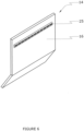
- FIG. 2 An elevator system 1 according to the present invention is shown in figure 2 , wherein the lift car 2 further comprises a toe guard 14.
- the toe guard 14 comprises a flat plate 15 mounted below the lift car doorway sill 12 to extend vertically below the lift car floor 7 so that a planar face 16 of the flat plate 15 is proximate to a vertical wall 17 of the lift shaft 3.
- the toe guard 14 further comprises a bent section 18 that extends out of alignment from the flat plate 15 along a lower edge 19 of the flat plate 15, the bent section 18 extending away from the vertical wall 17 of the lift shaft 3.
- the toe guard 14 extends along the full width of the lift car 2. In the event the lift car 2 stops above the level of the landing 4 and the landing doors 6 are opened, the toe guard 14 protects waiting passengers standing on the landing 4 from exposure to the lift shaft 3 through the space between the landing 4 and the lift car floor 7.
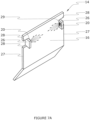
- the toe guard 14 further comprises a luminaire 20 mounted to the flat plate 15 to illuminate the vertical wall 17 of the lift shaft 3. Light from the luminaire 20 reflects off the vertical wall 17 of the lift shaft 3 to illuminate the gap between the respective landing and lift car sills 13/12.
- the gap between the respective landing and lift car sills 13/12 is herein referred to as the running clearance 21.
- the lift car 2 of figure 2 is shown stopped with the lift car floor 7 and landing 4 misaligned so that the lift car floor 7 is disposed a distance above the landing 4 sufficient to present a trip hazard to passengers entering the lift car 2.
- the elevator system determines that the lift car 2 has stopped and so opens both the lift car and landing doors 11/6 so that passengers may enter and exit the lift car 2.
- Light from the luminaire 20 reflects from the vertical wall 17 of the lift shaft 3 to impinge upon the toe guard 14, therefore illuminating the toe guard 14 to passengers entering the lift car 2 and warning them of the trip hazard presented by the lift car sill 12 as a result of the misalignment of the lift car floor 7 and landing 4.
- the lift car 2 of figure 2 is shown stopped with the lift car floor 7 and landing 4 misaligned so that the lift car floor 7 is disposed a distance below the landing 4 sufficient to present a trip hazard to passengers exiting the lift car 2.
- the elevator system determines that the lift car 2 has stopped and so opens both the lift car and landing doors 11/6 so that passengers may enter and exit the lift car 2.
- Light from the luminaire 20 reflects from the vertical wall 17 of the lift shaft 3 to illuminate the vertical wall 17 of the lift shaft 3 to passengers exiting the lift car 2 and warning them of the trip hazard created by the misalignment of the lift car floor 7 and landing 4.
- the luminaire 20 is mounted to the planar face 16 of the toe guard 14 a distance (d) below the lift car floor 7.
- the distance (d) is selected such that the luminaire 20 remains below the level of the lift car floor 7 and the landing 4 when the lift car and landing doors 11/6 are open so that passengers are not in line of sight of the luminaire 20; therefore passengers looking directly at the running clearance 21 are not dazzled.
- the elevator system may be configured to prevent the lift car doors 11 and or the landing doors 6 from opening if the lift car floor 7 and the landing 4 exceed a maximum accepted level of misalignment.
- the distance (d) is selected to be greater than the maximum accepted level of misalignment such that the luminaire 20 remains below the level of the lift car floor 7 and the landing 4 when the lift car and landing doors 11/6 are open.
- the maximum accepted level of misalignment is between 50 and 300 millimetres. In a preferred embodiment, the maximum accepted level of misalignment is 100 millimetres.
- the maximum accepted level of misalignment may be a level at which the lift will become disabled if any further misalignment occurs or at which an alarm will sound to warn a lift operator that a maximum acceptable level of misalignment has been exceeded and maintenance to the lift is required.
- the distance (d) below the lift car floor 7 that the luminaire 20 is mounted will determine the intensity of light visible to passengers. Moving the mounting point of the luminaire 20 in a direction further below the lift car floor 7 will reduce the intensity of light reflected toward a passenger.
- the luminaire 20 may be permanently illuminated when the elevator system is in operation.
- the luminaire 20 may be configured to be illuminated only when required so as to save energy.
- the luminaire is configured to be illuminated only when the lift car doors 11 are open on receipt of an electrical signal from the lift car door opening apparatus.
- the luminaire 20 is configured to be illuminated by a motion sensor so that the luminaire 20 is switched on as a passenger approaches the running clearance 21.
- the luminaire 20 is configured to be illuminated at the same time as the lift car lighting.
- the luminaire 20 may only illuminate if a misalignment, or a certain level of misalignment, is detected. It will also be appreciated that the luminaire may not be illuminated continuously but may flash or strobe to enhance the visibility of the misalignment to a user.
- the luminaire may take a number of forms and be mounted in a number of ways as described in more detail below.
- a toe guard 14 according to an embodiment of the present invention is shown in figure 5 , an opening 22 is formed in the toe guard 14 into which a luminaire 20 is mounted.
- This provides the advantage that the luminaire 20 can be recessed in the toe guard 14 so that a portion of the luminaire body 23 is located behind the toe guard 14, distal to the vertical wall 17 of the lift shaft 3.
- This enables a light emitting portion 24 of the luminaire 20 to be flush with or recessed from a face 16 of the toe guard 14 proximate to the vertical wall 17 of the lift shaft 3. Therefore, a larger luminaire 20 can be used in elevator systems where the clearance between the face of the toe guard 16 and the vertical wall 17 of the lift shaft 3 would be limiting.
- the light emitting portion 24 of the luminaire 20 is spaced further from the vertical wall 17 of the lift shaft 3 than if mounted proud of the face 16 of the toe guard 14. It shall be appreciated that this increases the spread of light incident on the vertical wall 17 of the lift shaft 3 and therefore increases the proportion of light, and thus the intensity of light, reflected toward a passenger. Likewise moving the light emitting portion 24 of the luminaire 20 closer to the vertical wall 17 of the lift shaft 3 reduces the proportion of light, and thus the intensity of light, reflected toward a passenger.
- any number of openings 22 may be provided in the toe guard 14 for any number of luminaires 20 to be mounted therein.
- the distribution and positioning of the openings 22 may be selected as required, for example, in one unillustrated embodiment, a plurality of luminaires 20 are provided and are mounted in respective openings 22 arranged in a row extending transversely across the width of the toe guard 14.
- Figure 6 shows an embodiment not covered by the claimed invention.
- linear luminaires 25 such as strip LED lighting are mounted to the face 16 of the toe guard 14. Therefore, no further modification of the toe guard 14 is required reducing the complexity of the device and the installation time.
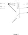
- FIGs 7A and 7B show embodiments not covered by the claimed invention.
- the toe guard 14 is modified further to provide mounting surfaces 26 perpendicular to the face 16 of the toe guard 14.
- the mounting surfaces 26 are formed from a portion of the toe guard adjacent vertical edges 27 of the toe guard 14. Said portion of the toe guard 14 is delineated by pairs of cut lines 28 extending perpendicular from each vertical edge 27 and a bend line 29 extending between distal ends of each pair of cut lines 28.
- each of said portions is bent away from the toe guard 14 along said bend lines 29 to extend perpendicular to the face 16 of the toe guard 14.
- Luminaires 20 are mounted to the mounting surfaces 26 so that light shines transversely across the face 16 of the toe guard 14 toward an opposing vertical edge 27.
- L shaped brackets 30 are mounted to the face 16 of the toe guard 14.
- Each L shaped bracket 30 has a base plate 31 which is attached to the toe guard 14 by any suitable means and a mounting plate 32 upstanding perpendicularly from one edge of the base plate 31 to which a luminaire 20 is mounted.
- the bracket 30 is oriented such that light from the luminaire 20 shines transversely across the face 16 of the toe guard 14 toward one of said vertical edges 27 of the toe guard 14.
- bracket 30 may alternatively be mounted so that the luminaire 20 is oriented in any desired direction.
- the luminaire 20 is oriented in any desired direction.
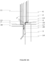
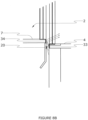
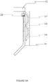
- the elevator system may additionally comprise first and second reflectors 33/34 as shown in figure 8A , wherein the first reflector 33 is mounted to the vertical wall 17 of the lift shaft 3 proximate to the landing sill 13 and extending along the full width of the sill 13, and the second reflector 34 is mounted along an upper end of the toe guard 14 proximate to the lift car door sill 12.
- the lift car 2 of figure 8A is shown stopped with the lift car floor 7 and the landing 4 misaligned so that the lift car floor 7 is disposed below the landing 4. With the lift car and landing doors 11/6 in the open position, passengers standing in the lift car are in direct line of sight of the first reflector 33. A portion of light emitted by the luminaire 20 is incident on the first reflector 33 and is reflected toward the passengers standing in the lift car 2.
- the lift car 2 of figure 8A is shown stopped with the lift car floor 7 and the landing 4 misaligned so that the lift car floor 7 is disposed above the landing 4.
- passengers standing on the landing 4 are in direct line of sight of the second reflector 34.
- a portion of light emitted by the luminaire 20 is reflected by the first reflector 33 so that a portion of reflected light is incident on the second reflector 34 whereupon it is reflected toward the passengers standing in the lift car 2.
- the gap or running clearance 21 acts as a light guide to guide the light in an upward direction along the gap as it is reflected off the opposing walls and until it emerges from the gap and is visible to passengers.
- the reflectors may act to diffuse the light to reduce its intensity and/or glare.
- the respective reflectors are configured to increase the intensity of light reflected toward passengers and therefore increase the visibility of a trip hazard.
- the luminaire 20 is mounted a distance below the respective landing 4 greater than the maximum accepted level of misalignment so that the luminaire 20 remains below the level of the lift car floor 7 and the landing 4 when the lift car and landing doors 11/6 are open.
- Figures 9A to 9C illustrate further embodiments not covered by the claimed invention, in such unclaimed embodiments the toe guard 14 is made of a translucent material with at least one luminaire 20 mounted to direct light into the translucent toe guard 14. This has the effect of diffusing the emitted light so that it is spread out and softened.
- one or more luminaires 20 are embedded into the translucent toe guard 14 adjacent the lift car sill 12 and arranged to direct light to diffuse through said toe guard 14 toward the lower edge 19 of the toe guard 14.
- luminaires 20 are mounted along the vertical edges 27 of the translucent toe guard 14 to direct light to diffuse through said toe guard 14 toward the respective opposing edge 27.
- one or more luminaires 20 are mounted to a back face 36 of the translucent toe guard 14.
- the luminaires 20 are attached to a mounting frame 35 which extends away from the back face 36 in order to support the luminaires 20 at a distance from the back face 36.
- the spread of light incident on the back face 36 is increased so that light diffused through the toe guard 14 is more evenly emitted from the opposing planar face 16 of the toe guard 14.
- the toe guard 14 may instead be transparent and the one or more luminaires 20 mounted a distance below the lift car sill 12 so that, when the lift car floor 7 and the landing 4 are within the maximum accepted level of misalignment, light is transmitted through the transparent toe guard 14 toward the vertical wall 17 of the lift shaft 3.
- the luminaire 20 may be any appropriate lighting device, though preferably the luminaire 20 is an LED lighting device such as an LED strip light or an LED spot light.
- LED lighting device such as an LED strip light or an LED spot light.
- multiple coloured LEDs may be provided. It is envisaged that multiple coloured LEDs provide the option of changing the colour of light used to illuminate the running clearance 21 according to the floor level. Further, it is envisaged that the colour of the LED light may be set according to the lift operators preferences.
- the method may be carried out on existing lift car systems to retrofit them with the luminaire according to the invention.
Landscapes
- Elevator Door Apparatuses (AREA)
- Cage And Drive Apparatuses For Elevators (AREA)
Claims (6)
- Verfahren zur Adaption eines Aufzugssystems, um Aufzugsbenutzer vor einer vertikalen Fehlausrichtung zwischen einem Boden (7) einer Aufzugskabine (2) und einer Landefläche (4) zu warnen, an der die Aufzugskabine (2) anhält, und wo ein Spalt zwischen gegenüberliegenden parallelen Wänden (14, 17) vorhanden ist, die von einer Vorderkante des Aufzugskabinenbodens (7) bzw. einer Vorderkante der Landefläche (4) vertikal nach unten abhängen, wobei das Verfahren Positionieren einer Leuchte (20) an der Wand (14), die von einer Vorderkante des Aufzugskabinenbodens vertikal nach unten abhängt, beinhaltet, sodass die Leuchte (20) unabhängig von der vertikalen Fehlausrichtung Licht auf die gegenüberliegende Wand (17) lenkt, und sodass zumindest ein Abschnitt des Lichts der Leuchte (20) von der gegenüberliegenden Wand (17) reflektiert wird, bevor es aus dem Spalt austritt, wobei die Wand (14), die von der Vorderkante des Aufzugskabinenbodens (7) nach unten abhängt, ein Zehenschutz (14) ist, der eine flache Platte (15) umfasst, die unterhalb einer Aufzugskabinentürschwelle (12) angebracht ist, sodass sie sich vertikal unter dem Aufzugskabinenboden (7) und der Aufzugskabinentürschwelle (12) erstreckt, und wobei das Verfahren den Schritt zum Positionieren einer Leuchte (20) auf der Platte (15) beinhaltet, sodass die Leuchte vertikal unterhalb der Aufzugskabinentürschwelle (12) positioniert ist;
dadurch gekennzeichnet, dass der Zehenschutz (14) eine Öffnung (22) umfasst, wobei das Verfahren den Schritt zum Positionieren einer Leuchte (20) in der Öffnung (22) umfasst, sodass sie bündig mit einer Vorderfläche des Zehenschutzes (14) abschließt oder darunter zurückgesetzt ist. - Verfahren zur Adaption eines Aufzugssystems nach Anspruch 1, wobei das Aufzugssystem ein maximal zulässiges Maß an Fehlausrichtung aufweist, bei dem das Aufzugssystem betriebsfähig bleibt, und das Verfahren Positionieren der Leuchte (20) in einem Abstand unterhalb der Kante des Aufzugskabinenbodens um einen Abstand umfasst, der größer als das maximal zulässige Maß an Fehlausrichtung ist.
- Verfahren zur Adaption eines Aufzugssystems nach einem der vorhergehenden Ansprüche, wobei die Leuchte (20) eine LED-Streifenleuchte ist und das Verfahren den Schritt zum Montieren der LED-Streifenleuchte an der Wand (14) beinhaltet.
- Aufzugssystem, umfassend eine Aufzugskabine (2), wobei das System dazu eingerichtet ist, Aufzugsbenutzer vor einer vertikalen Fehlausrichtung zwischen einem Boden (7) der Aufzugskabine (2) und einer Landefläche (4) zu warnen, an der die Aufzugskabine (2) anhält, und wo ein Spalt zwischen gegenüberliegenden parallelen Wänden (14, 17) vorhanden ist, die von einer Vorderkante des Aufzugskabinenbodens (7) bzw. einer Vorderkante der Landefläche (4) vertikal nach unten abhängen, wobei das System eine Leuchte (20) an der Wand (14), die von einer Vorderkante des Aufzugskabinenbodens vertikal nach unten abhängt, beinhaltet, wobei die Leuchte (20) dazu konfiguriert ist, unabhängig von der vertikalen Ausrichtung Licht auf die gegenüberliegende Wand (17) zu lenken, sodass zumindest ein Abschnitt des Lichts der Leuchte (20) von der gegenüberliegenden Wand (17) reflektiert wird, bevor es aus dem Spalt austritt, wobei die Wand (14), die von der Vorderkante des Aufzugskabinenbodens (7) nach unten abhängt, ein Zehenschutz (14) ist, der eine flache Platte (15) umfasst, die unterhalb einer Aufzugskabinentürschwelle (12) angebracht ist, sodass sie sich vertikal unter dem Aufzugskabinenboden (7) und der Aufzugskabinentürschwelle (12) erstreckt, und wobei die Leuchte (20) auf der Platte (15) positioniert ist, sodass die Leuchte vertikal unterhalb der Aufzugskabinentürschwelle (12) positioniert ist;
dadurch gekennzeichnet, dass der Zehenschutz (14) eine Öffnung (22) umfasst, wobei die Leuchte (20) in der Öffnung (22) aufgenommen ist, sodass ein lichtemittierender Abschnitt (24) der Leuchte (20) bündig mit einer Vorderseite (16) des Zehenschutzes (14) abschließt oder darunter zurückgesetzt ist. - Aufzugssystem nach Anspruch 4, wobei ein maximal zulässiges Maß an Fehlausrichtung zwischen dem Aufzugskabinenboden (7) und der Landefläche (4) gilt, bei dem das Aufzugssystem betriebsfähig bleibt, wobei die Leuchte (20) in einem Abstand unterhalb der Kante positioniert ist, um einen Abstand, der größer als das maximal zulässige Maß an Fehlausrichtung ist.
- Aufzugssystem nach einem der vorhergehenden Ansprüche, wobei die Leuchte (20) eine LED-Streifenleuchte ist.
Applications Claiming Priority (3)
| Application Number | Priority Date | Filing Date | Title |
|---|---|---|---|
| GBGB1506645.9A GB201506645D0 (en) | 2015-04-20 | 2015-04-20 | An elevator system and a method of adapting an elevator system |
| GB1510912.7A GB2537695B (en) | 2015-04-20 | 2015-06-22 | Elevator trip hazard light system and method |
| PCT/GB2016/050712 WO2016170301A1 (en) | 2015-04-20 | 2016-03-16 | An elevator system and a method of adapting an elevator system |
Publications (3)
| Publication Number | Publication Date |
|---|---|
| EP3286125A1 EP3286125A1 (de) | 2018-02-28 |
| EP3286125C0 EP3286125C0 (de) | 2024-01-03 |
| EP3286125B1 true EP3286125B1 (de) | 2024-01-03 |
Family
ID=53298829
Family Applications (1)
| Application Number | Title | Priority Date | Filing Date |
|---|---|---|---|
| EP16713007.9A Active EP3286125B1 (de) | 2015-04-20 | 2016-03-16 | Aufzugsystem und verfahren zur adaption eines aufzugssystems |
Country Status (4)
| Country | Link |
|---|---|
| US (1) | US10773927B2 (de) |
| EP (1) | EP3286125B1 (de) |
| GB (2) | GB201506645D0 (de) |
| WO (1) | WO2016170301A1 (de) |
Families Citing this family (3)
| Publication number | Priority date | Publication date | Assignee | Title |
|---|---|---|---|---|
| CN108951787B (zh) * | 2018-08-30 | 2020-04-28 | 陶辰晨 | 一种公共厕所智能化冲厕装置 |
| CN112027856B (zh) * | 2020-09-15 | 2021-10-22 | 周胡琴 | 一种电梯升降安全运行系统 |
| CN118373292A (zh) * | 2024-05-24 | 2024-07-23 | 上海三菱电梯有限公司 | 一种电梯层门系统 |
Citations (4)
| Publication number | Priority date | Publication date | Assignee | Title |
|---|---|---|---|---|
| JPH0692562A (ja) * | 1992-09-11 | 1994-04-05 | Hitachi Ltd | エレベータ装置 |
| JPH07252065A (ja) * | 1994-03-10 | 1995-10-03 | Mitsubishi Denki Bill Techno Service Kk | エレベーターの安全装置 |
| JPH10305981A (ja) * | 1997-05-02 | 1998-11-17 | Hitachi Building Syst Co Ltd | エレベータの敷居装置 |
| EP2746208A1 (de) * | 2012-12-18 | 2014-06-25 | Nauled S.r.l. | Schwellensignalisierungseinheit einer fahrbaren Anlage |
Family Cites Families (11)
| Publication number | Priority date | Publication date | Assignee | Title |
|---|---|---|---|---|
| GB8319629D0 (en) * | 1983-07-20 | 1983-08-24 | Connor L O | Winding package of tape |
| JPS60137773U (ja) * | 1984-02-21 | 1985-09-12 | 株式会社東芝 | エレベ−タ |
| JPH07228459A (ja) | 1994-02-14 | 1995-08-29 | Mitsubishi Denki Bill Techno Service Kk | 昇降機の敷居段差報知装置および戸閉まり報知装置 |
| US5609224A (en) * | 1995-05-31 | 1997-03-11 | Otis Elevator Company | Elevator door sill |
| JP3958940B2 (ja) * | 2001-03-12 | 2007-08-15 | 三菱電機株式会社 | 扉装置及びエレベータ装置 |
| JP2003146567A (ja) * | 2001-11-13 | 2003-05-21 | Hitachi Building Systems Co Ltd | エレベーター用かご停止位置警報装置 |
| WO2006045211A1 (de) * | 2004-10-25 | 2006-05-04 | Inventio Ag | Aufzugsanlage mit einem lichtmodul im türschwellenprofil |
| JP4786329B2 (ja) * | 2005-12-20 | 2011-10-05 | 三菱電機株式会社 | エレベータードアの引込まれ防止装置 |
| JP2012071971A (ja) * | 2010-09-29 | 2012-04-12 | Mitsubishi Electric Building Techno Service Co Ltd | エレベーター躓き防止装置 |
| FI20106044L (fi) * | 2010-10-11 | 2012-04-12 | Kone Corp | Hissi |
| EP2739557B1 (de) * | 2011-06-28 | 2015-11-11 | Airdri Limited | Verfahren und vorrichtung für gefahrenverweise |
-
2015
- 2015-04-20 GB GBGB1506645.9A patent/GB201506645D0/en not_active Ceased
- 2015-06-22 GB GB1510912.7A patent/GB2537695B/en active Active
-
2016
- 2016-03-16 WO PCT/GB2016/050712 patent/WO2016170301A1/en not_active Ceased
- 2016-03-16 EP EP16713007.9A patent/EP3286125B1/de active Active
- 2016-03-16 US US15/568,298 patent/US10773927B2/en active Active
Patent Citations (4)
| Publication number | Priority date | Publication date | Assignee | Title |
|---|---|---|---|---|
| JPH0692562A (ja) * | 1992-09-11 | 1994-04-05 | Hitachi Ltd | エレベータ装置 |
| JPH07252065A (ja) * | 1994-03-10 | 1995-10-03 | Mitsubishi Denki Bill Techno Service Kk | エレベーターの安全装置 |
| JPH10305981A (ja) * | 1997-05-02 | 1998-11-17 | Hitachi Building Syst Co Ltd | エレベータの敷居装置 |
| EP2746208A1 (de) * | 2012-12-18 | 2014-06-25 | Nauled S.r.l. | Schwellensignalisierungseinheit einer fahrbaren Anlage |
Also Published As
| Publication number | Publication date |
|---|---|
| GB2537695A (en) | 2016-10-26 |
| US10773927B2 (en) | 2020-09-15 |
| US20180148299A1 (en) | 2018-05-31 |
| EP3286125A1 (de) | 2018-02-28 |
| EP3286125C0 (de) | 2024-01-03 |
| WO2016170301A1 (en) | 2016-10-27 |
| GB201506645D0 (en) | 2015-06-03 |
| GB201510912D0 (en) | 2015-08-05 |
| US20180334364A9 (en) | 2018-11-22 |
| GB2537695B (en) | 2018-06-13 |
Similar Documents
| Publication | Publication Date | Title |
|---|---|---|
| EP3286125B1 (de) | Aufzugsystem und verfahren zur adaption eines aufzugssystems | |
| EP2292548B1 (de) | Mehrzweckkantenvorrichtung für angetriebene Türen | |
| EP3686148B1 (de) | Sicherheitsvorrichtung für eine fahrtreppe und fahrtreppe mit der sicherheitsvorrichtung | |
| CN103896143B (zh) | 乘客传送设备以及乘客传送设备的照明方法 | |
| US20190084799A1 (en) | Lighting systems for elevator systems | |
| CN101535161A (zh) | 电梯装置 | |
| CN102153009A (zh) | 开门行驶时的电梯卡合部件避免碰撞系统及方法 | |
| EP4158108B1 (de) | Strassensperre mit beleuchtungssystem | |
| EP2839445B1 (de) | In den boden integrierbares führungssystem | |
| ES2661258T3 (es) | Panel iluminable para una escalera mecánica, un pasillo rodante o una cabina de ascensor | |
| CN104159844A (zh) | 电梯的出入口装置 | |
| KR200493162Y1 (ko) | 엘리베이터용 진행표시장치 | |
| JP2004224529A (ja) | エレベータの着床検出装置 | |
| JP4559258B2 (ja) | 乗客コンベア | |
| US12398021B2 (en) | Passenger transport system with a disinfecting device | |
| JP4260497B2 (ja) | エレベータ乗場のドア装置 | |
| FI119255B (fi) | Läpinäkyvä ovi ja menetelmä läpinäkyvän oven törmäyksen estoon | |
| CN111315674A (zh) | 电梯轿厢 | |
| EP3216738A1 (de) | Stockwerk offset warnung durch licht aus schweller | |
| JP7716915B2 (ja) | 乗客コンベヤの欄干照明装置 | |
| JP2002037056A (ja) | プラットホームドア装置の安全装置 | |
| KR0135436B1 (ko) | 버스용 실내조명장치 | |
| JP2714199B2 (ja) | 乗客コンベア | |
| JP3381289B2 (ja) | エレベーターかごの脚光照明装置 | |
| JP2006188301A (ja) | 乗客コンベアの乗客検出装置 |
Legal Events
| Date | Code | Title | Description |
|---|---|---|---|
| STAA | Information on the status of an ep patent application or granted ep patent |
Free format text: STATUS: THE INTERNATIONAL PUBLICATION HAS BEEN MADE |
|
| PUAI | Public reference made under article 153(3) epc to a published international application that has entered the european phase |
Free format text: ORIGINAL CODE: 0009012 |
|
| STAA | Information on the status of an ep patent application or granted ep patent |
Free format text: STATUS: REQUEST FOR EXAMINATION WAS MADE |
|
| 17P | Request for examination filed |
Effective date: 20171110 |
|
| AK | Designated contracting states |
Kind code of ref document: A1 Designated state(s): AL AT BE BG CH CY CZ DE DK EE ES FI FR GB GR HR HU IE IS IT LI LT LU LV MC MK MT NL NO PL PT RO RS SE SI SK SM TR |
|
| AX | Request for extension of the european patent |
Extension state: BA ME |
|
| DAV | Request for validation of the european patent (deleted) | ||
| DAX | Request for extension of the european patent (deleted) | ||
| STAA | Information on the status of an ep patent application or granted ep patent |
Free format text: STATUS: EXAMINATION IS IN PROGRESS |
|
| 17Q | First examination report despatched |
Effective date: 20190816 |
|
| GRAP | Despatch of communication of intention to grant a patent |
Free format text: ORIGINAL CODE: EPIDOSNIGR1 |
|
| STAA | Information on the status of an ep patent application or granted ep patent |
Free format text: STATUS: GRANT OF PATENT IS INTENDED |
|
| INTG | Intention to grant announced |
Effective date: 20230905 |
|
| GRAS | Grant fee paid |
Free format text: ORIGINAL CODE: EPIDOSNIGR3 |
|
| GRAA | (expected) grant |
Free format text: ORIGINAL CODE: 0009210 |
|
| STAA | Information on the status of an ep patent application or granted ep patent |
Free format text: STATUS: THE PATENT HAS BEEN GRANTED |
|
| RIN1 | Information on inventor provided before grant (corrected) |
Inventor name: COURTNELL, LEWIS Inventor name: PERCIVAL, IAN |
|
| AK | Designated contracting states |
Kind code of ref document: B1 Designated state(s): AL AT BE BG CH CY CZ DE DK EE ES FI FR GB GR HR HU IE IS IT LI LT LU LV MC MK MT NL NO PL PT RO RS SE SI SK SM TR |
|
| REG | Reference to a national code |
Ref country code: GB Ref legal event code: FG4D |
|
| REG | Reference to a national code |
Ref country code: CH Ref legal event code: EP |
|
| REG | Reference to a national code |
Ref country code: DE Ref legal event code: R096 Ref document number: 602016085115 Country of ref document: DE |
|
| REG | Reference to a national code |
Ref country code: IE Ref legal event code: FG4D |
|
| U01 | Request for unitary effect filed |
Effective date: 20240201 |
|
| U07 | Unitary effect registered |
Designated state(s): AT BE BG DE DK EE FI FR IT LT LU LV MT NL PT SE SI Effective date: 20240208 |
|
| PG25 | Lapsed in a contracting state [announced via postgrant information from national office to epo] |
Ref country code: ES Free format text: LAPSE BECAUSE OF FAILURE TO SUBMIT A TRANSLATION OF THE DESCRIPTION OR TO PAY THE FEE WITHIN THE PRESCRIBED TIME-LIMIT Effective date: 20240103 |
|
| PG25 | Lapsed in a contracting state [announced via postgrant information from national office to epo] |
Ref country code: ES Free format text: LAPSE BECAUSE OF FAILURE TO SUBMIT A TRANSLATION OF THE DESCRIPTION OR TO PAY THE FEE WITHIN THE PRESCRIBED TIME-LIMIT Effective date: 20240103 |
|
| U20 | Renewal fee for the european patent with unitary effect paid |
Year of fee payment: 9 Effective date: 20240423 |
|
| PG25 | Lapsed in a contracting state [announced via postgrant information from national office to epo] |
Ref country code: IS Free format text: LAPSE BECAUSE OF FAILURE TO SUBMIT A TRANSLATION OF THE DESCRIPTION OR TO PAY THE FEE WITHIN THE PRESCRIBED TIME-LIMIT Effective date: 20240503 |
|
| PG25 | Lapsed in a contracting state [announced via postgrant information from national office to epo] |
Ref country code: GR Free format text: LAPSE BECAUSE OF FAILURE TO SUBMIT A TRANSLATION OF THE DESCRIPTION OR TO PAY THE FEE WITHIN THE PRESCRIBED TIME-LIMIT Effective date: 20240404 |
|
| PG25 | Lapsed in a contracting state [announced via postgrant information from national office to epo] |
Ref country code: RS Free format text: LAPSE BECAUSE OF FAILURE TO SUBMIT A TRANSLATION OF THE DESCRIPTION OR TO PAY THE FEE WITHIN THE PRESCRIBED TIME-LIMIT Effective date: 20240403 Ref country code: HR Free format text: LAPSE BECAUSE OF FAILURE TO SUBMIT A TRANSLATION OF THE DESCRIPTION OR TO PAY THE FEE WITHIN THE PRESCRIBED TIME-LIMIT Effective date: 20240103 |
|
| PG25 | Lapsed in a contracting state [announced via postgrant information from national office to epo] |
Ref country code: CZ Free format text: LAPSE BECAUSE OF FAILURE TO SUBMIT A TRANSLATION OF THE DESCRIPTION OR TO PAY THE FEE WITHIN THE PRESCRIBED TIME-LIMIT Effective date: 20240103 |
|
| PG25 | Lapsed in a contracting state [announced via postgrant information from national office to epo] |
Ref country code: RS Free format text: LAPSE BECAUSE OF FAILURE TO SUBMIT A TRANSLATION OF THE DESCRIPTION OR TO PAY THE FEE WITHIN THE PRESCRIBED TIME-LIMIT Effective date: 20240403 Ref country code: NO Free format text: LAPSE BECAUSE OF FAILURE TO SUBMIT A TRANSLATION OF THE DESCRIPTION OR TO PAY THE FEE WITHIN THE PRESCRIBED TIME-LIMIT Effective date: 20240403 Ref country code: IS Free format text: LAPSE BECAUSE OF FAILURE TO SUBMIT A TRANSLATION OF THE DESCRIPTION OR TO PAY THE FEE WITHIN THE PRESCRIBED TIME-LIMIT Effective date: 20240503 Ref country code: HR Free format text: LAPSE BECAUSE OF FAILURE TO SUBMIT A TRANSLATION OF THE DESCRIPTION OR TO PAY THE FEE WITHIN THE PRESCRIBED TIME-LIMIT Effective date: 20240103 Ref country code: GR Free format text: LAPSE BECAUSE OF FAILURE TO SUBMIT A TRANSLATION OF THE DESCRIPTION OR TO PAY THE FEE WITHIN THE PRESCRIBED TIME-LIMIT Effective date: 20240404 Ref country code: CZ Free format text: LAPSE BECAUSE OF FAILURE TO SUBMIT A TRANSLATION OF THE DESCRIPTION OR TO PAY THE FEE WITHIN THE PRESCRIBED TIME-LIMIT Effective date: 20240103 |
|
| PG25 | Lapsed in a contracting state [announced via postgrant information from national office to epo] |
Ref country code: PL Free format text: LAPSE BECAUSE OF FAILURE TO SUBMIT A TRANSLATION OF THE DESCRIPTION OR TO PAY THE FEE WITHIN THE PRESCRIBED TIME-LIMIT Effective date: 20240103 |
|
| PG25 | Lapsed in a contracting state [announced via postgrant information from national office to epo] |
Ref country code: PL Free format text: LAPSE BECAUSE OF FAILURE TO SUBMIT A TRANSLATION OF THE DESCRIPTION OR TO PAY THE FEE WITHIN THE PRESCRIBED TIME-LIMIT Effective date: 20240103 |
|
| REG | Reference to a national code |
Ref country code: DE Ref legal event code: R097 Ref document number: 602016085115 Country of ref document: DE |
|
| PG25 | Lapsed in a contracting state [announced via postgrant information from national office to epo] |
Ref country code: SM Free format text: LAPSE BECAUSE OF FAILURE TO SUBMIT A TRANSLATION OF THE DESCRIPTION OR TO PAY THE FEE WITHIN THE PRESCRIBED TIME-LIMIT Effective date: 20240103 |
|
| PG25 | Lapsed in a contracting state [announced via postgrant information from national office to epo] |
Ref country code: SK Free format text: LAPSE BECAUSE OF FAILURE TO SUBMIT A TRANSLATION OF THE DESCRIPTION OR TO PAY THE FEE WITHIN THE PRESCRIBED TIME-LIMIT Effective date: 20240103 |
|
| PG25 | Lapsed in a contracting state [announced via postgrant information from national office to epo] |
Ref country code: SM Free format text: LAPSE BECAUSE OF FAILURE TO SUBMIT A TRANSLATION OF THE DESCRIPTION OR TO PAY THE FEE WITHIN THE PRESCRIBED TIME-LIMIT Effective date: 20240103 Ref country code: SK Free format text: LAPSE BECAUSE OF FAILURE TO SUBMIT A TRANSLATION OF THE DESCRIPTION OR TO PAY THE FEE WITHIN THE PRESCRIBED TIME-LIMIT Effective date: 20240103 Ref country code: RO Free format text: LAPSE BECAUSE OF FAILURE TO SUBMIT A TRANSLATION OF THE DESCRIPTION OR TO PAY THE FEE WITHIN THE PRESCRIBED TIME-LIMIT Effective date: 20240103 |
|
| PLBE | No opposition filed within time limit |
Free format text: ORIGINAL CODE: 0009261 |
|
| STAA | Information on the status of an ep patent application or granted ep patent |
Free format text: STATUS: NO OPPOSITION FILED WITHIN TIME LIMIT |
|
| PG25 | Lapsed in a contracting state [announced via postgrant information from national office to epo] |
Ref country code: MC Free format text: LAPSE BECAUSE OF FAILURE TO SUBMIT A TRANSLATION OF THE DESCRIPTION OR TO PAY THE FEE WITHIN THE PRESCRIBED TIME-LIMIT Effective date: 20240103 |
|
| PG25 | Lapsed in a contracting state [announced via postgrant information from national office to epo] |
Ref country code: MC Free format text: LAPSE BECAUSE OF FAILURE TO SUBMIT A TRANSLATION OF THE DESCRIPTION OR TO PAY THE FEE WITHIN THE PRESCRIBED TIME-LIMIT Effective date: 20240103 |
|
| 26N | No opposition filed |
Effective date: 20241007 |
|
| GBPC | Gb: european patent ceased through non-payment of renewal fee |
Effective date: 20240403 |
|
| PG25 | Lapsed in a contracting state [announced via postgrant information from national office to epo] |
Ref country code: GB Free format text: LAPSE BECAUSE OF NON-PAYMENT OF DUE FEES Effective date: 20240403 |
|
| PG25 | Lapsed in a contracting state [announced via postgrant information from national office to epo] |
Ref country code: IE Free format text: LAPSE BECAUSE OF NON-PAYMENT OF DUE FEES Effective date: 20240316 |
|
| PG25 | Lapsed in a contracting state [announced via postgrant information from national office to epo] |
Ref country code: IE Free format text: LAPSE BECAUSE OF NON-PAYMENT OF DUE FEES Effective date: 20240316 Ref country code: GB Free format text: LAPSE BECAUSE OF NON-PAYMENT OF DUE FEES Effective date: 20240403 |
|
| U20 | Renewal fee for the european patent with unitary effect paid |
Year of fee payment: 10 Effective date: 20250314 |
|
| PGFP | Annual fee paid to national office [announced via postgrant information from national office to epo] |
Ref country code: CH Payment date: 20250401 Year of fee payment: 10 |
|
| PG25 | Lapsed in a contracting state [announced via postgrant information from national office to epo] |
Ref country code: CY Free format text: LAPSE BECAUSE OF FAILURE TO SUBMIT A TRANSLATION OF THE DESCRIPTION OR TO PAY THE FEE WITHIN THE PRESCRIBED TIME-LIMIT; INVALID AB INITIO Effective date: 20160316 |
|
| PG25 | Lapsed in a contracting state [announced via postgrant information from national office to epo] |
Ref country code: HU Free format text: LAPSE BECAUSE OF FAILURE TO SUBMIT A TRANSLATION OF THE DESCRIPTION OR TO PAY THE FEE WITHIN THE PRESCRIBED TIME-LIMIT; INVALID AB INITIO Effective date: 20160316 |
|
| PG25 | Lapsed in a contracting state [announced via postgrant information from national office to epo] |
Ref country code: TR Free format text: LAPSE BECAUSE OF FAILURE TO SUBMIT A TRANSLATION OF THE DESCRIPTION OR TO PAY THE FEE WITHIN THE PRESCRIBED TIME-LIMIT Effective date: 20240103 |