EP2276953B1 - Umspritzte oder einpressmuffe für hydraulische führung eines magnetventils - Google Patents
Umspritzte oder einpressmuffe für hydraulische führung eines magnetventils Download PDFInfo
- Publication number
- EP2276953B1 EP2276953B1 EP09739381.3A EP09739381A EP2276953B1 EP 2276953 B1 EP2276953 B1 EP 2276953B1 EP 09739381 A EP09739381 A EP 09739381A EP 2276953 B1 EP2276953 B1 EP 2276953B1
- Authority
- EP
- European Patent Office
- Prior art keywords
- valve
- valve body
- metal insert
- fluid passage
- port
- Prior art date
- Legal status (The legal status is an assumption and is not a legal conclusion. Google has not performed a legal analysis and makes no representation as to the accuracy of the status listed.)
- Active
Links
Images
Classifications
-
- F—MECHANICAL ENGINEERING; LIGHTING; HEATING; WEAPONS; BLASTING
- F16—ENGINEERING ELEMENTS AND UNITS; GENERAL MEASURES FOR PRODUCING AND MAINTAINING EFFECTIVE FUNCTIONING OF MACHINES OR INSTALLATIONS; THERMAL INSULATION IN GENERAL
- F16K—VALVES; TAPS; COCKS; ACTUATING-FLOATS; DEVICES FOR VENTING OR AERATING
- F16K31/00—Actuating devices; Operating means; Releasing devices
- F16K31/02—Actuating devices; Operating means; Releasing devices electric; magnetic
- F16K31/06—Actuating devices; Operating means; Releasing devices electric; magnetic using a magnet, e.g. diaphragm valves, cutting off by means of a liquid
- F16K31/0644—One-way valve
- F16K31/0668—Sliding valves
-
- F—MECHANICAL ENGINEERING; LIGHTING; HEATING; WEAPONS; BLASTING
- F16—ENGINEERING ELEMENTS AND UNITS; GENERAL MEASURES FOR PRODUCING AND MAINTAINING EFFECTIVE FUNCTIONING OF MACHINES OR INSTALLATIONS; THERMAL INSULATION IN GENERAL
- F16K—VALVES; TAPS; COCKS; ACTUATING-FLOATS; DEVICES FOR VENTING OR AERATING
- F16K11/00—Multiple-way valves, e.g. mixing valves; Pipe fittings incorporating such valves
- F16K11/02—Multiple-way valves, e.g. mixing valves; Pipe fittings incorporating such valves with all movable sealing faces moving as one unit
- F16K11/06—Multiple-way valves, e.g. mixing valves; Pipe fittings incorporating such valves with all movable sealing faces moving as one unit comprising only sliding valves, i.e. sliding closure elements
- F16K11/065—Multiple-way valves, e.g. mixing valves; Pipe fittings incorporating such valves with all movable sealing faces moving as one unit comprising only sliding valves, i.e. sliding closure elements with linearly sliding closure members
- F16K11/07—Multiple-way valves, e.g. mixing valves; Pipe fittings incorporating such valves with all movable sealing faces moving as one unit comprising only sliding valves, i.e. sliding closure elements with linearly sliding closure members with cylindrical slides
- F16K11/0716—Multiple-way valves, e.g. mixing valves; Pipe fittings incorporating such valves with all movable sealing faces moving as one unit comprising only sliding valves, i.e. sliding closure elements with linearly sliding closure members with cylindrical slides with fluid passages through the valve member
-
- F—MECHANICAL ENGINEERING; LIGHTING; HEATING; WEAPONS; BLASTING
- F16—ENGINEERING ELEMENTS AND UNITS; GENERAL MEASURES FOR PRODUCING AND MAINTAINING EFFECTIVE FUNCTIONING OF MACHINES OR INSTALLATIONS; THERMAL INSULATION IN GENERAL
- F16K—VALVES; TAPS; COCKS; ACTUATING-FLOATS; DEVICES FOR VENTING OR AERATING
- F16K27/00—Construction of housing; Use of materials therefor
- F16K27/04—Construction of housing; Use of materials therefor of sliding valves
- F16K27/048—Electromagnetically actuated valves
-
- F—MECHANICAL ENGINEERING; LIGHTING; HEATING; WEAPONS; BLASTING
- F16—ENGINEERING ELEMENTS AND UNITS; GENERAL MEASURES FOR PRODUCING AND MAINTAINING EFFECTIVE FUNCTIONING OF MACHINES OR INSTALLATIONS; THERMAL INSULATION IN GENERAL
- F16K—VALVES; TAPS; COCKS; ACTUATING-FLOATS; DEVICES FOR VENTING OR AERATING
- F16K3/00—Gate valves or sliding valves, i.e. cut-off apparatus with closing members having a sliding movement along the seat for opening and closing
- F16K3/22—Gate valves or sliding valves, i.e. cut-off apparatus with closing members having a sliding movement along the seat for opening and closing with sealing faces shaped as surfaces of solids of revolution
- F16K3/24—Gate valves or sliding valves, i.e. cut-off apparatus with closing members having a sliding movement along the seat for opening and closing with sealing faces shaped as surfaces of solids of revolution with cylindrical valve members
- F16K3/26—Gate valves or sliding valves, i.e. cut-off apparatus with closing members having a sliding movement along the seat for opening and closing with sealing faces shaped as surfaces of solids of revolution with cylindrical valve members with fluid passages in the valve member
- F16K3/262—Gate valves or sliding valves, i.e. cut-off apparatus with closing members having a sliding movement along the seat for opening and closing with sealing faces shaped as surfaces of solids of revolution with cylindrical valve members with fluid passages in the valve member with a transverse bore in the valve member
-
- F—MECHANICAL ENGINEERING; LIGHTING; HEATING; WEAPONS; BLASTING
- F16—ENGINEERING ELEMENTS AND UNITS; GENERAL MEASURES FOR PRODUCING AND MAINTAINING EFFECTIVE FUNCTIONING OF MACHINES OR INSTALLATIONS; THERMAL INSULATION IN GENERAL
- F16K—VALVES; TAPS; COCKS; ACTUATING-FLOATS; DEVICES FOR VENTING OR AERATING
- F16K31/00—Actuating devices; Operating means; Releasing devices
- F16K31/02—Actuating devices; Operating means; Releasing devices electric; magnetic
- F16K31/06—Actuating devices; Operating means; Releasing devices electric; magnetic using a magnet, e.g. diaphragm valves, cutting off by means of a liquid
- F16K31/0603—Multiple-way valves
- F16K31/061—Sliding valves
- F16K31/0613—Sliding valves with cylindrical slides
-
- H—ELECTRICITY
- H01—ELECTRIC ELEMENTS
- H01F—MAGNETS; INDUCTANCES; TRANSFORMERS; SELECTION OF MATERIALS FOR THEIR MAGNETIC PROPERTIES
- H01F7/00—Magnets
- H01F7/06—Electromagnets; Actuators including electromagnets
- H01F7/08—Electromagnets; Actuators including electromagnets with armatures
- H01F7/081—Magnetic constructions
- H01F2007/085—Yoke or polar piece between coil bobbin and armature having a gap, e.g. filled with nonmagnetic material
-
- H—ELECTRICITY
- H01—ELECTRIC ELEMENTS
- H01F—MAGNETS; INDUCTANCES; TRANSFORMERS; SELECTION OF MATERIALS FOR THEIR MAGNETIC PROPERTIES
- H01F7/00—Magnets
- H01F7/06—Electromagnets; Actuators including electromagnets
- H01F7/08—Electromagnets; Actuators including electromagnets with armatures
- H01F7/16—Rectilinearly-movable armatures
- H01F7/1607—Armatures entering the winding
-
- Y—GENERAL TAGGING OF NEW TECHNOLOGICAL DEVELOPMENTS; GENERAL TAGGING OF CROSS-SECTIONAL TECHNOLOGIES SPANNING OVER SEVERAL SECTIONS OF THE IPC; TECHNICAL SUBJECTS COVERED BY FORMER USPC CROSS-REFERENCE ART COLLECTIONS [XRACs] AND DIGESTS
- Y10—TECHNICAL SUBJECTS COVERED BY FORMER USPC
- Y10T—TECHNICAL SUBJECTS COVERED BY FORMER US CLASSIFICATION
- Y10T137/00—Fluid handling
- Y10T137/8593—Systems
- Y10T137/86493—Multi-way valve unit
- Y10T137/86574—Supply and exhaust
- Y10T137/86622—Motor-operated
-
- Y—GENERAL TAGGING OF NEW TECHNOLOGICAL DEVELOPMENTS; GENERAL TAGGING OF CROSS-SECTIONAL TECHNOLOGIES SPANNING OVER SEVERAL SECTIONS OF THE IPC; TECHNICAL SUBJECTS COVERED BY FORMER USPC CROSS-REFERENCE ART COLLECTIONS [XRACs] AND DIGESTS
- Y10—TECHNICAL SUBJECTS COVERED BY FORMER USPC
- Y10T—TECHNICAL SUBJECTS COVERED BY FORMER US CLASSIFICATION
- Y10T137/00—Fluid handling
- Y10T137/8593—Systems
- Y10T137/86493—Multi-way valve unit
- Y10T137/86574—Supply and exhaust
- Y10T137/8667—Reciprocating valve
- Y10T137/86694—Piston valve
- Y10T137/86702—With internal flow passage
-
- Y—GENERAL TAGGING OF NEW TECHNOLOGICAL DEVELOPMENTS; GENERAL TAGGING OF CROSS-SECTIONAL TECHNOLOGIES SPANNING OVER SEVERAL SECTIONS OF THE IPC; TECHNICAL SUBJECTS COVERED BY FORMER USPC CROSS-REFERENCE ART COLLECTIONS [XRACs] AND DIGESTS
- Y10—TECHNICAL SUBJECTS COVERED BY FORMER USPC
- Y10T—TECHNICAL SUBJECTS COVERED BY FORMER US CLASSIFICATION
- Y10T29/00—Metal working
- Y10T29/49—Method of mechanical manufacture
- Y10T29/49405—Valve or choke making
- Y10T29/49412—Valve or choke making with assembly, disassembly or composite article making
Definitions
- the present invention relates to overmolded solenoid valve bodies, and more specially solenoid valves having metal sleeves pressed in or overmolded to a composite valve body.
- Solenoid valves for automotive components have become common place in the industry.
- the solenoid valves are used to control various hydraulic components such as transmission, clutch, turbocharger, drive line components, and exhaust control components.
- solenoid valves have a valve body that is actuated by a solenoid portion which consists of an electromagnetic coil having an armature that moves in response to the application of current to the electromagnetic portion.
- a solenoid valve is known for example from US 2005/0218363 A .
- the valve bodies have been made out of machined metal components.
- the flow path through the valve body has been defined by forming holes and bores in the metal valve body.
- the trend in solenoid designs has been to increase their ability through the use of more complex flow paths through the valve body itself.
- valves with composite valve bodies being disposed around a metal insert, wherein the fluid passage is formed within the metal insert as disclosed in DE 103 40 932 A1 .
- the present invention relates to a valve having a metal insert with a fluid passage formed in the metal insert.
- a composite valve body is disposed at least partially around the metal insert and having at least one port in fluid communication with the fluid passage of the metal insert.
- a valve member is partially disposed in the metal insert and operable to control the fluid flow through the fluid passage of the metal insert and parts of the valve body.
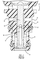
- the valve assembly 10 has a metal valve body 12 having machined ports 14 which are typically formed in the metal valve body 12 by boring or milling through the metal valve body 12.
- the machined ports 14 extend into a machined bore 15 which is also formed in the metal valve body 12.
- a valve member 16 is slideably positioned within the machined bore 15 of the metal valve body 12.
- the valve member 16 has a fluid passage 18 that is used to communicate fluid between the machined ports.
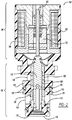
- Fig. 2 is a cross-sectional view of a valve assembly 100 in accordance with the present embodiment of the invention.
- the valve assembly 100 has a valve portion 102 and an actuator portion 104.
- the actuator portion 104 and valve portion 102 can be separate or integrated and be made from the same material.
- the valve portion 102 has a composite valve body 110 that is made of a composite material which is molded from composite resin.
- the composite material that makes up the composite body 110 would be any type of suitable plastic material. More specifically, thermal plastics such as polyamids, including nylon, polyphthalamides, and liquid crystal polymers. However, the principle materials used are not necessarily limited to these particular materials, other plastic materials may be more suitable for a particular application.
- the composite valve body 110 has several ports molded therein.
- the ports include a supply port 114, control port 116, and exhaust port 118.
- Each of the ports 114, 116, 118 extend to a bore of the composite valve body 110.
- the bore of the valve body 113 is formed through the molding process or processes described below. Additionally, the greater numbers of ports can be implemented based on the design of a particular application.
- a metal insert 106 Within the bore 113 of the composite valve body 110 is a metal insert 106.
- the fluid passage 108 is formed by machining the metal insert 106.
- the metal insert 106 is positioned in the bore 113 of the composite valve body 110.
- the metal insert 106 can be placed within the bore 113 of the composite valve body 110 by overmolding the composite valve body 110 around the metal insert 106. Another process involves press fitting the metal insert 106 into the already formed valve body 110.
- the apertures 109 of the metal insert 106 are configured to align with one or more of the ports 114, 116, 118 of the composite valve body 110. This allows for fluid communication from outside of the composite valve body 110 to flow into the fluid passage 108 of the metal insert 106.
- a valve member 112 is slideably positioned within the metal insert 106 and has a fluid passage 119 formed therein.
- the fluid passage 119 in this particular embodiment communicates with the control port 116 and the supply port 114 and exhaust port 118 through metering orifices 126.
- the metal insert 106 has metering lands 128 formed in the fluid passage 108 of the metal insert 106.
- the metering lands 128 align with the metering orifices 126 and function to control the flow of fluid through the metering orifices 126 when the valve member 112 is placed in a position where the metering orifices 126 are aligned with the metering lands 128.
- the metering lands 128 have metering edges 126 that permit the flow of fluid through the metering orifices 126 when the valve member 112 is moved axially within the fluid passage 108 of the metal insert 106.
- the valve assembly 100 of the present embodiment significantly reduces the production cost and manufacturing time when compared to the prior art valve of Fig. 1 .
- the composite valve body 110 is less expensive and easier to form than the metal valve body 12.
- the metal insert 106 and the valve member 112 are the only components that have to be machined. These components are smaller and present less metal that has to be machined. Additionally, the valve member 112 and metal inset 106 can be preassembled and checked for quality prior to being placed in the composite valve body 110. This also saves time and even allows the metal insert 106 and valve member 112 to be manufactured separately which also presents cost savings.
- the valve assembly 100 has an actuator portion 104 which in the present invention is a solenoid portion.
- the actuator portion has a housing 105 that can be a separate component; however, in this particular embodiment of the invention the housing 105 is a composite housing that is integral with the composite valve body 100 of the valve portion 102.
- Within the actuator portion 104 is a coil 120 that when energized causes an armature 122 to move axially.
- a pin 123 is connected to the armature 122 and contacts the valve member 112 of the valve portion 102 in order to cause the valve member 112 to move axially within the metal insert 106.
- the present invention provides a composite valve body 110 that is formed by molding composite resins. This lowers the over all cost of production and also provides the advantage of being able to form more complex fluid passages within the composite valve body 110 while eliminating the machining step that would normally be required for a metal valve body 12 as shown in Fig. 1 . Furthermore, there are fluid passages that can be molded into the composite valve body 110 that could not be easily formed in a traditional metal valve body 12.
- the present description also includes a method of making a composite solenoid valve or valve assembly 100 as shown in Fig. 2 .
- the method of making the valve assembly 100 includes providing the metal insert 106, composite valve body 110, valve member 112, fluid passage 119 of the metal insert 106, and at least one port 114, 116, 118 in the composite valve body 110 and apertures 109 in the metal insert 106.
- the step of forming the fluid passage 119 in the metal insert 106 is carried out by machining or drilling the fluid passage from metal stock.
- the valve member 112 also has fluid passages 119 and apertures 126 machined or formed by machining and boring the passages out of the valve member 112. While the present invention describes a valve member 112 that is formed of metal it is within the scope of this invention to have the valve member 112 also formed from composite material whereby the fluid passages and apertures are formed through a molding process. The valve member 112 has been placed in the fluid passage 108 of the metal insert 106.
- the valve member 112 is then placed in a slidable arrangement within the fluid passage 108 of the metal insert 106.
- the metal insert 106 is then connected to the composite valve body 110.
- This process can be carried out in several different ways.
- One process is to press fit the metal insert 106 into an already formed composite valve body 110.
- Another step involves placing the metal insert 106 into a mold and then overmolding the composite valve body 110 around the metal insert 106.
- the supply port 114, control port 116, and exhaust port 118 are formed in the composite valve body 110 either through the overmolding process or by drilling the ports through the formed composite valve body 110.
- the metal insert 106 may have a stepped or mold feature on its exterior surface such that in order to more tightly secure the metal insert 106 to the valve body 110. Such features will eliminate any possible leaking that can occur between the plastic and the metal and also to insure retention of the metal insert.
- the actuator portion 104 is separate from the valve portion 102 then the actuator is connected to the composite valve body 110.
- the casing 105 of the actuator portion 104 can be overmolded in the same or separate step as the metal insert 106 is overmolded with the composite valve body 110.
- the casing 105 of the actuator portion 104 can be integral with the composite valve body 110.
Claims (6)
- Ventil, umfassend:einen Ventilabschnitt (102) mit einem Ventilkörper (110) und einem Fluiddurchgang (108);einen Versorgungsanschluss (114), der durch den Ventilkörper (110) angeordnet ist, wobei der Versorgungsanschluss (114) mit dem Fluiddurchgang (108) verbunden ist;einen Steueranschluss (116), der durch den Ventilkörper (110) angeordnet ist, wobei der Steueranschluss (116) mit dem Fluiddurchgang (108) verbunden ist;einen Abluftanschluss (118), der durch den Ventilkörper (110) angeordnet ist, wobei der Abluftanschluss (118) mit dem Fluiddurchgang (108) verbunden ist; undein Ventilelement (112) zum Steuern des Flusses des Fluidmediums zwischen dem Versorgungsanschluss (114) und dem Steueranschluss (116), wobei das Ventilelement (112) den Fluss des Fluidmediums zwischen dem Steueranschluss (116) und entweder dem Versorgungsanschluss (114) oder dem Abluftanschluss (118) durch Bewegen in Bezug auf den Ventilkörper (110) steuert; undeinen Metalleinsatz (106), der den Fluiddurchgang (108) darin ausgebildet aufweist, der Ventilkörper (110) ein Verbundventilkörper (110) ist, wobei der Verbundventilkörper (110) eine Bohrung (113) aufweist, wo der Metalleinsatz (106) positioniert ist, wobei der Verbundventilkörper (110) mindestens teilweise rund um den Metalleinsatz (106) angeordnet ist,dadurch gekennzeichnet, dassdas Ventil ferner umfassteinen Solenoidabschnitt mit einer Spule (120) mit einem Anker (122), der innerhalb des Solenoidabschnitts in Reaktion auf die Bestromung der Spule (120) bewegbar ist, wobei der Anker (122) funktionsmäßig konfiguriert ist, mit dem Ventilelement (112) in Kontakt zu treten und er bewirkt, dass das Ventilelement (112) sich innerhalb des Fluiddurchgangs (108) verschiebt,eine Feder, die funktionsmäßig mit dem Anker (122) zum Vorspannen des Ankers (122) in eine Richtung verbunden ist, wenn die Spule (120) nicht bestromt ist,einen Dosiersteg (128), der in dem Fluiddurchgang (108) zum Steuern des Flusses des Fluidmediums durch den Fluiddurchgang (108) ausgebildet ist,wobei der Metalleinsatz (106) den Dosiersteg (128) darstellt,und eine Dosieröffnung (126) zum fluidmäßigen Kommunizieren von dem Fluiddurchgang (108) mit mindestens einem von dem Steueranschluss (116), dem Versorgungsanschluss (114) und dem Abluftanschluss (118), wobei der Dosiersteg (128) mit der Dosieröffnung (126) zum Steuern des Flusses des Fluidmediums durch die Dosieröffnung (126) in Eingriff bringbar ist, undSteuerkanten (130) zum Dosieren des Flusses des Fluidmediums durch die Dosieröffnung (126) aufweist,wobei das Ventilelement (112) eine Bohrung aufweist, die sich mindestens teilweise durch das Ventilelement (112) zum Vorsehen des Flusses des Fluidmediums zwischen dem Versorgungsanschluss (114) und dem Steueranschluss (116) erstreckt und wobei die Dosieröffnung (126) sich durch das Ventilelement (112) zwischen der Bohrung und dem Fluiddurchgang (108) erstreckt.
- Ventil nach Anspruch 1, wobei der Verbundventilkörper (110) aus einem thermoplastischen Material besteht.
- Ventil nach einem der vorhergehenden Ansprüche, wobei der Metalleinsatz (106) obere und untere Lager aufweist.
- Ventil nach einem der vorhergehenden Ansprüche, wobei der Metalleinsatz (106) eine oder mehrere Öffnungen (109) aufweist, die sich von einer Außenseite des Metalleinsatzes (106) zu dem Fluiddurchgang (108) erstrecken, der in dem Metalleinsatz (106) ausgebildet ist, wobei die eine oder mehreren Öffnungen (109) zur Ausrichtung mit mindestens einem von dem Steueranschluss (116), dem Versorgungsanschluss (114) und dem Abluftanschluss (118) konfiguriert sind.
- Ventil nach Anspruch 1, wobei der Versorgungsanschluss (114),das Steuerteil (116) und das Abluftteil (118) durch den Metalleinsatz (106) angeordnet sind.
- Ventil nach Anspruch 1, wobei der Verbundventilkörper (110) mindestens teilweise rund um den Metalleinsatz (106) umspritzt ist.
Priority Applications (2)
| Application Number | Priority Date | Filing Date | Title |
|---|---|---|---|
| EP19000253.5A EP3550188A1 (de) | 2008-04-28 | 2009-04-02 | Ventil umfassend eine umspritzte oder einpressmuffe für hydraulische magnetführung |
| EP17001640.6A EP3296600B1 (de) | 2008-04-28 | 2009-04-02 | Umspritzte oder einpressmuffe für hydraulische magnetführung |
Applications Claiming Priority (2)
| Application Number | Priority Date | Filing Date | Title |
|---|---|---|---|
| US12570308P | 2008-04-28 | 2008-04-28 | |
| PCT/US2009/039287 WO2009134579A2 (en) | 2008-04-28 | 2009-04-02 | Overmolded or pressed-in sleeve for hydraulic routing of solenoid |
Related Child Applications (3)
| Application Number | Title | Priority Date | Filing Date |
|---|---|---|---|
| EP17001640.6A Division EP3296600B1 (de) | 2008-04-28 | 2009-04-02 | Umspritzte oder einpressmuffe für hydraulische magnetführung |
| EP17001640.6A Division-Into EP3296600B1 (de) | 2008-04-28 | 2009-04-02 | Umspritzte oder einpressmuffe für hydraulische magnetführung |
| EP19000253.5A Division EP3550188A1 (de) | 2008-04-28 | 2009-04-02 | Ventil umfassend eine umspritzte oder einpressmuffe für hydraulische magnetführung |
Publications (3)
| Publication Number | Publication Date |
|---|---|
| EP2276953A2 EP2276953A2 (de) | 2011-01-26 |
| EP2276953A4 EP2276953A4 (de) | 2015-12-16 |
| EP2276953B1 true EP2276953B1 (de) | 2018-05-23 |
Family
ID=41255663
Family Applications (3)
| Application Number | Title | Priority Date | Filing Date |
|---|---|---|---|
| EP19000253.5A Withdrawn EP3550188A1 (de) | 2008-04-28 | 2009-04-02 | Ventil umfassend eine umspritzte oder einpressmuffe für hydraulische magnetführung |
| EP17001640.6A Revoked EP3296600B1 (de) | 2008-04-28 | 2009-04-02 | Umspritzte oder einpressmuffe für hydraulische magnetführung |
| EP09739381.3A Active EP2276953B1 (de) | 2008-04-28 | 2009-04-02 | Umspritzte oder einpressmuffe für hydraulische führung eines magnetventils |
Family Applications Before (2)
| Application Number | Title | Priority Date | Filing Date |
|---|---|---|---|
| EP19000253.5A Withdrawn EP3550188A1 (de) | 2008-04-28 | 2009-04-02 | Ventil umfassend eine umspritzte oder einpressmuffe für hydraulische magnetführung |
| EP17001640.6A Revoked EP3296600B1 (de) | 2008-04-28 | 2009-04-02 | Umspritzte oder einpressmuffe für hydraulische magnetführung |
Country Status (4)
| Country | Link |
|---|---|
| US (4) | US8757209B2 (de) |
| EP (3) | EP3550188A1 (de) |
| CN (1) | CN102007331B (de) |
| WO (1) | WO2009134579A2 (de) |
Cited By (1)
| Publication number | Priority date | Publication date | Assignee | Title |
|---|---|---|---|---|
| WO2024032975A1 (de) * | 2022-08-10 | 2024-02-15 | Thomas Magnete Gmbh | Ventilanordnung und elektrohydraulisches ventil |
Families Citing this family (35)
| Publication number | Priority date | Publication date | Assignee | Title |
|---|---|---|---|---|
| WO2008039500A1 (en) * | 2006-09-26 | 2008-04-03 | Borgwarner Inc. | Direct-acting pilot pressure control solenoid |
| US8757209B2 (en) | 2008-04-28 | 2014-06-24 | Borgwarner, Inc. | Overmolded or pressed-in sleeve for hydraulic routing of solenoid |
| WO2012015679A2 (en) * | 2010-07-30 | 2012-02-02 | Borgwarner Inc. | Integrated plastic solenoid module |
| US20150101674A1 (en) * | 2012-12-20 | 2015-04-16 | Hydril Usa Distribution, Llc | Subsea pressure regulator |
| JP6200219B2 (ja) * | 2013-06-24 | 2017-09-20 | Kyb株式会社 | ソレノイドバルブおよび緩衝器 |
| US9497889B2 (en) | 2014-02-27 | 2016-11-15 | Sandisk Technologies Llc | Heat dissipation for substrate assemblies |
| DE102015221300A1 (de) * | 2015-10-30 | 2017-05-04 | Continental Automotive Gmbh | Ventil |
| US10907740B2 (en) * | 2015-12-15 | 2021-02-02 | Husco Automotive Holdings Llc | Control valve having a metal sleeve within a plastic valve body |
| DE102016109865A1 (de) * | 2016-05-30 | 2017-11-30 | Eto Magnetic Gmbh | Elektromagnetische Ventilvorrichtung und System |
| EP3261102A1 (de) | 2016-06-23 | 2017-12-27 | Rain Bird Corporation | Universeller elektromagnet |
| DE202016104309U1 (de) * | 2016-08-01 | 2017-11-03 | Eto Magnetic Gmbh | Elektromagnetische Ventilvorrichtung und System |
| KR101918532B1 (ko) * | 2016-12-28 | 2018-11-15 | 주식회사 유니크 | 솔레노이드 밸브 |
| JP6932146B2 (ja) | 2017-01-26 | 2021-09-08 | イーグル工業株式会社 | 容量制御弁 |
| US11542930B2 (en) | 2017-02-18 | 2023-01-03 | Eagle Industry Co., Ltd. | Capacity control valve |
| US10980120B2 (en) | 2017-06-15 | 2021-04-13 | Rain Bird Corporation | Compact printed circuit board |
| DE102017214506A1 (de) * | 2017-08-21 | 2019-02-21 | Robert Bosch Gmbh | Proportionalventil zum Steuern eines gasförmigen Mediums |
| US10927974B2 (en) * | 2017-10-10 | 2021-02-23 | ECO Holding 1 GmbH | Hydraulic valve in particular a hydraulic transmission valve |
| KR102336134B1 (ko) | 2017-11-15 | 2021-12-07 | 이구루코교 가부시기가이샤 | 용량 제어 밸브 및 용량 제어 밸브의 제어 방법 |
| EP3719364B1 (de) * | 2017-11-30 | 2023-11-15 | Eagle Industry Co., Ltd. | Kapazitätssteuerventil und steuerverfahren für kapazitätssteuerventil |
| WO2019112025A1 (ja) | 2017-12-08 | 2019-06-13 | イーグル工業株式会社 | 容量制御弁及び容量制御弁の制御方法 |
| KR102570268B1 (ko) * | 2017-12-13 | 2023-08-24 | 한스 옌젠 루브리케이터스 에이/에스 | 대형 저속 동작 2 행정 엔진 및 그 엔진을 윤활하는 방법, 그 엔진 및 방법을 위한 윤활제 인젝터 및 그 사용방법 |
| JP7190444B2 (ja) | 2017-12-14 | 2022-12-15 | イーグル工業株式会社 | 容量制御弁及び容量制御弁の制御方法 |
| CN111465767B (zh) | 2017-12-27 | 2022-09-02 | 伊格尔工业股份有限公司 | 容量控制阀及容量控制阀的控制方法 |
| JP7171616B2 (ja) | 2017-12-27 | 2022-11-15 | イーグル工業株式会社 | 容量制御弁及び容量制御弁の制御方法 |
| EP3744976B1 (de) | 2018-01-22 | 2023-06-14 | Eagle Industry Co., Ltd. | Kapazitätssteuerungsventil |
| US11503782B2 (en) | 2018-04-11 | 2022-11-22 | Rain Bird Corporation | Smart drip irrigation emitter |
| JP7242663B2 (ja) * | 2018-05-23 | 2023-03-20 | イーグル工業株式会社 | 容量制御弁 |
| US10598298B2 (en) | 2018-08-27 | 2020-03-24 | Borg Warner Inc. | Control valve and hydraulic control module including the same |
| WO2020110925A1 (ja) | 2018-11-26 | 2020-06-04 | イーグル工業株式会社 | 容量制御弁 |
| US11391388B2 (en) | 2018-12-04 | 2022-07-19 | Eagle Industry Co., Ltd. | Capacity control valve |
| CN109458490B (zh) * | 2018-12-24 | 2024-02-06 | 南京菡束环保设备有限公司 | 一种排水装置及在净水过程中控制浓缩水排放的系统 |
| WO2021010259A1 (ja) * | 2019-07-12 | 2021-01-21 | イーグル工業株式会社 | 容量制御弁 |
| JP7459612B2 (ja) | 2020-03-27 | 2024-04-02 | ニデックパワートレインシステムズ株式会社 | 電磁弁 |
| JP7463803B2 (ja) | 2020-03-27 | 2024-04-09 | ニデックパワートレインシステムズ株式会社 | 電磁弁 |
| US11721465B2 (en) | 2020-04-24 | 2023-08-08 | Rain Bird Corporation | Solenoid apparatus and methods of assembly |
Citations (1)
| Publication number | Priority date | Publication date | Assignee | Title |
|---|---|---|---|---|
| DE10340932A1 (de) * | 2003-09-05 | 2005-03-31 | Kendrion Binder Magnete Gmbh | Schieberventil und Verfahren zum Herstellen eines Schieberventils |
Family Cites Families (54)
| Publication number | Priority date | Publication date | Assignee | Title |
|---|---|---|---|---|
| US2522249A (en) * | 1946-03-23 | 1950-09-12 | Glenn L Martin Co | Diverter valve deflector |
| DE1207603B (de) * | 1961-02-11 | 1965-12-23 | Friedrich Stuebbe | Verfahren zum Herstellen von Kuekenhaehnen |
| US3574311A (en) * | 1969-03-05 | 1971-04-13 | Stewart Warner Corp | Spool valve |
| US3643700A (en) * | 1970-08-24 | 1972-02-22 | Delbert L Black | Valve |
| GB1433795A (en) * | 1973-10-05 | 1976-04-28 | Bridon Engineering Ltd | Valves |
| US3927830A (en) * | 1974-09-25 | 1975-12-23 | Borg Warner | Control valve |
| JPS55163582U (de) * | 1979-05-14 | 1980-11-25 | ||
| JPS55163582A (en) | 1979-06-07 | 1980-12-19 | Kikai Shinko Kokai | Display unit having arithmetic mechanism |
| DE3137328A1 (de) | 1981-09-19 | 1983-04-07 | Alfred Teves Gmbh, 6000 Frankfurt | Schieberventil |
| DE3224119A1 (de) | 1982-06-29 | 1983-12-29 | Robert Bosch Gmbh, 7000 Stuttgart | Hydraulisches elektromagnetisch betaetigtes schieberventil |
| US4538645A (en) * | 1983-08-16 | 1985-09-03 | Ambac Industries, Inc. | Control valve assembly |
| JPS60108561A (ja) | 1983-11-15 | 1985-06-14 | Nippon Denso Co Ltd | 燃料分配管 |
| US4790513A (en) * | 1983-11-17 | 1988-12-13 | General Motors Corporation | Solenoid valve assembly |
| JPS61141878A (ja) | 1984-12-14 | 1986-06-28 | Shimadzu Corp | アンモニア分析装置 |
| US4988077A (en) * | 1985-06-03 | 1991-01-29 | Kerotest Manufacturing Corp. | Reinforced plastic valve |
| US5076537A (en) * | 1990-07-19 | 1991-12-31 | Evc, Inc. | Electromechanical servovalve |
| JP2963253B2 (ja) * | 1991-10-07 | 1999-10-18 | 本田技研工業株式会社 | ソレノイドバルブの取付構造 |
| DE4221757C2 (de) | 1992-07-02 | 1997-05-15 | Rexroth Mannesmann Gmbh | Magnetbetätigtes Proportional-Wegeventil |
| DE4317786C1 (de) | 1993-05-28 | 1994-11-10 | Luk Fahrzeug Hydraulik | Ventilanordnung |
| US5358215A (en) * | 1993-06-25 | 1994-10-25 | Borg-Warner Automotive, Inc. | Encapsulated solenoid operated valve assembly |
| DE4328709C2 (de) * | 1993-08-26 | 1996-04-04 | Bosch Gmbh Robert | Elektromagnetventil |
| DE4332948A1 (de) * | 1993-09-28 | 1995-03-30 | Bosch Gmbh Robert | Elektromagnetventil, insbesondere Schaltventil für Automatikgetriebe von Kraftfahrzeugen |
| US5513673A (en) * | 1994-05-23 | 1996-05-07 | Lectron Products, Inc. | Electrically modulated pressure regulator valve with variable force solenoid |
| JP3666072B2 (ja) * | 1995-09-13 | 2005-06-29 | アイシン精機株式会社 | 切替弁 |
| US5551482A (en) * | 1995-11-13 | 1996-09-03 | Hr Textron Inc. | Plastic servovalve |
| JPH10222237A (ja) | 1997-02-04 | 1998-08-21 | Hitachi Constr Mach Co Ltd | 遠隔操作装置 |
| US6041807A (en) | 1997-04-09 | 2000-03-28 | Toyoda Koki Kabushiki Kaisha | Flow control device of power steering apparatus |
| US5778932A (en) * | 1997-06-04 | 1998-07-14 | Vickers, Incorporated | Electrohydraulic proportional pressure reducing-relieving valve |
| JP3017702B2 (ja) * | 1997-09-10 | 2000-03-13 | 川崎重工業株式会社 | ソレノイド |
| DE19745802B4 (de) | 1997-10-16 | 2006-12-14 | Robert Bosch Gmbh | Mehrwegeventilgehäuse aus spritzgegossenem Kunststoff mit integrierten Führungselementen |
| US5890662A (en) | 1997-11-10 | 1999-04-06 | Outboard Marine Corporation | Solenoid with variable magnetic path |
| JP3666246B2 (ja) * | 1998-05-25 | 2005-06-29 | Nok株式会社 | ソレノイドバルブ |
| DE19847021B4 (de) | 1998-10-13 | 2007-01-04 | Robert Bosch Gmbh | Druckregelventil |
| US6012700A (en) * | 1998-10-22 | 2000-01-11 | Snap-Tite Technolgoies, Inc. | Overmolded solenoid valve |
| EP1031731B1 (de) * | 1999-02-22 | 2006-06-07 | Hydraulik-Ring GmbH | Wegesitzventil |
| FR2793532B1 (fr) | 1999-05-12 | 2001-08-03 | Mannesmann Rexroth Sa | Dispositif distributeur de fluide notamment pour telecommande hydraulique |
| DE10028567A1 (de) | 1999-06-10 | 2000-12-14 | Borgwarner Inc | Elektromechanisches Solenoidventil mit veränderlicher Kraft zur Hydraulikdrucksteuerung |
| US6526864B2 (en) * | 2001-04-17 | 2003-03-04 | Csa Engineering, Inc. | Piezoelectrically actuated single-stage servovalve |
| DE10163235A1 (de) * | 2001-12-21 | 2003-07-10 | Daimler Chrysler Ag | Elektromagnetventil, insbesondere für Automatikgetriebe |
| DE10218759B4 (de) | 2002-04-26 | 2004-08-19 | Bosch Rexroth Ag | Pneumatisches Schieberventil mit einem zweiteiligen Ventilgehäuse aus Kunststoff |
| DE10242407A1 (de) | 2002-09-12 | 2004-03-25 | Robert Bosch Gmbh | Druckregler |
| US6966329B2 (en) * | 2003-01-27 | 2005-11-22 | Hydraforce, Inc. | Proportional pilot-operated flow control valve |
| DE10359364B4 (de) | 2003-12-18 | 2012-10-11 | Schaeffler Technologies Gmbh & Co. Kg | Elektromagnetisches Hydraulikventil, insbesondere 3/2-Wegeschaltventil zur Steuerung eines varialblen Ventiltriebes einer Brennkraftmaschine |
| US7258284B2 (en) * | 2003-12-19 | 2007-08-21 | Siemens Vdo Automotive Corporation | Fuel injector with a metering assembly having a seat molded to a polymeric support member |
| US7487798B2 (en) * | 2004-03-31 | 2009-02-10 | Keihin Corporation | Linear solenoid valve |
| JP4118262B2 (ja) * | 2004-07-14 | 2008-07-16 | トヨタ自動車株式会社 | バルブケース及び樹脂製シリンダヘッドカバー |
| JP2006064158A (ja) * | 2004-08-30 | 2006-03-09 | Mahle Filter Systems Japan Corp | 油路切換バルブの取付構造及びパッキン |
| WO2006095613A1 (ja) | 2005-03-09 | 2006-09-14 | Konica Minolta Medical & Graphic, Inc. | 希土類賦活アルカリ土類金属フッ化ハロゲン化物輝尽性蛍光体及びそれを用いた放射線画像変換パネル |
| DE102005049124A1 (de) | 2005-10-14 | 2007-04-19 | Continental Teves Ag & Co. Ohg | Elektromagnetventil |
| DE102005052481A1 (de) | 2005-11-03 | 2007-05-24 | Schaeffler Kg | Steuerventil für eine Vorrichtung zur variablen Einstellung der Steuerzeiten von Gaswechselventilen einer Brennkraftmaschine |
| WO2008039500A1 (en) | 2006-09-26 | 2008-04-03 | Borgwarner Inc. | Direct-acting pilot pressure control solenoid |
| US7766040B2 (en) * | 2007-03-13 | 2010-08-03 | Eaton Corporation | Pressure control valve assembly |
| US20080295800A1 (en) * | 2007-06-01 | 2008-12-04 | Bolinger Kim A | Composite body bore band |
| US8757209B2 (en) | 2008-04-28 | 2014-06-24 | Borgwarner, Inc. | Overmolded or pressed-in sleeve for hydraulic routing of solenoid |
-
2009
- 2009-04-02 US US12/988,811 patent/US8757209B2/en active Active
- 2009-04-02 EP EP19000253.5A patent/EP3550188A1/de not_active Withdrawn
- 2009-04-02 WO PCT/US2009/039287 patent/WO2009134579A2/en active Application Filing
- 2009-04-02 CN CN200980112989.2A patent/CN102007331B/zh active Active
- 2009-04-02 EP EP17001640.6A patent/EP3296600B1/de not_active Revoked
- 2009-04-02 EP EP09739381.3A patent/EP2276953B1/de active Active
-
2014
- 2014-05-02 US US14/268,047 patent/US9927045B2/en active Active
-
2018
- 2018-02-15 US US15/897,794 patent/US10962134B2/en active Active
-
2021
- 2021-02-24 US US17/183,869 patent/US11512791B2/en active Active
Patent Citations (1)
| Publication number | Priority date | Publication date | Assignee | Title |
|---|---|---|---|---|
| DE10340932A1 (de) * | 2003-09-05 | 2005-03-31 | Kendrion Binder Magnete Gmbh | Schieberventil und Verfahren zum Herstellen eines Schieberventils |
Cited By (1)
| Publication number | Priority date | Publication date | Assignee | Title |
|---|---|---|---|---|
| WO2024032975A1 (de) * | 2022-08-10 | 2024-02-15 | Thomas Magnete Gmbh | Ventilanordnung und elektrohydraulisches ventil |
Also Published As
| Publication number | Publication date |
|---|---|
| US20140239211A1 (en) | 2014-08-28 |
| US8757209B2 (en) | 2014-06-24 |
| EP2276953A4 (de) | 2015-12-16 |
| EP2276953A2 (de) | 2011-01-26 |
| EP3296600A1 (de) | 2018-03-21 |
| WO2009134579A3 (en) | 2010-01-07 |
| WO2009134579A2 (en) | 2009-11-05 |
| US20210190229A1 (en) | 2021-06-24 |
| CN102007331B (zh) | 2014-11-05 |
| EP3296600B1 (de) | 2019-07-10 |
| US20110089352A1 (en) | 2011-04-21 |
| CN102007331A (zh) | 2011-04-06 |
| US11512791B2 (en) | 2022-11-29 |
| US10962134B2 (en) | 2021-03-30 |
| US20180231139A1 (en) | 2018-08-16 |
| US9927045B2 (en) | 2018-03-27 |
| EP3550188A1 (de) | 2019-10-09 |
Similar Documents
| Publication | Publication Date | Title |
|---|---|---|
| US11512791B2 (en) | Overmolded or pressed-in sleeve for hydraulic routing of solenoid | |
| US6209563B1 (en) | Solenoid control valve | |
| EP1582791B1 (de) | Elektromagnetisches Ventil | |
| US8387644B2 (en) | Solenoid operated fluid control valve | |
| US9441732B2 (en) | Regulator valve with integrated direct acting solenoid | |
| US9091364B2 (en) | Slide valve having a housing and a slide element guided within the housing | |
| KR102042399B1 (ko) | 축 방향 공급 연결부를 구비한 압력 조절 밸브 | |
| US8714179B2 (en) | Solenoid valve | |
| US11333118B2 (en) | Solenoid-actuated valve and hydraulic control module including the same | |
| JP4089588B2 (ja) | 電磁弁 | |
| US8011385B2 (en) | Valve assembly and method of assembly | |
| KR20150072356A (ko) | 보상 챔버를 포함한 압력 조절 밸브 | |
| US8186370B2 (en) | Solenoid plunger core seal | |
| GB2333142A (en) | Servo control valve | |
| JPH02296084A (ja) | 電磁操作式方向制御弁 | |
| KR101663199B1 (ko) | 솔레노이드밸브와 일체로 형성되는 밸브바디 | |
| CN1734142A (zh) | 阀门装置 | |
| US20200126702A1 (en) | Solenoid having inverse tapered armature for solenoid-actuated valve | |
| US10927974B2 (en) | Hydraulic valve in particular a hydraulic transmission valve | |
| WO2012015679A2 (en) | Integrated plastic solenoid module | |
| US8205634B2 (en) | Hydraulic block | |
| WO2016047322A1 (ja) | 切換弁 | |
| US20080169439A1 (en) | Integrated two-stage low-leak control valve | |
| JPH07174106A (ja) | 電磁比例圧力制御弁 |
Legal Events
| Date | Code | Title | Description |
|---|---|---|---|
| PUAI | Public reference made under article 153(3) epc to a published international application that has entered the european phase |
Free format text: ORIGINAL CODE: 0009012 |
|
| 17P | Request for examination filed |
Effective date: 20101116 |
|
| AK | Designated contracting states |
Kind code of ref document: A2 Designated state(s): AT BE BG CH CY CZ DE DK EE ES FI FR GB GR HR HU IE IS IT LI LT LU LV MC MK MT NL NO PL PT RO SE SI SK TR |
|
| AX | Request for extension of the european patent |
Extension state: AL BA RS |
|
| DAX | Request for extension of the european patent (deleted) | ||
| A4 | Supplementary search report drawn up and despatched |
Effective date: 20151113 |
|
| RIC1 | Information provided on ipc code assigned before grant |
Ipc: F16K 31/06 20060101ALI20151109BHEP Ipc: F16K 27/04 20060101ALI20151109BHEP Ipc: H01F 7/08 20060101ALI20151109BHEP Ipc: H01F 7/16 20060101ALI20151109BHEP Ipc: F16K 3/26 20060101AFI20151109BHEP |
|
| REG | Reference to a national code |
Ref country code: DE Ref legal event code: R079 Ref document number: 602009052431 Country of ref document: DE Free format text: PREVIOUS MAIN CLASS: F16K0031060000 Ipc: F16K0003260000 |
|
| GRAP | Despatch of communication of intention to grant a patent |
Free format text: ORIGINAL CODE: EPIDOSNIGR1 |
|
| RIC1 | Information provided on ipc code assigned before grant |
Ipc: F16K 31/06 20060101ALI20161017BHEP Ipc: F16K 3/26 20060101AFI20161017BHEP Ipc: F16K 27/04 20060101ALI20161017BHEP Ipc: F16K 11/07 20060101ALI20161017BHEP Ipc: H01F 7/08 20060101ALI20161017BHEP Ipc: H01F 7/16 20060101ALI20161017BHEP |
|
| INTG | Intention to grant announced |
Effective date: 20161102 |
|
| TPAC | Observations filed by third parties |
Free format text: ORIGINAL CODE: EPIDOSNTIPA |
|
| GRAS | Grant fee paid |
Free format text: ORIGINAL CODE: EPIDOSNIGR3 |
|
| RBV | Designated contracting states (corrected) |
Designated state(s): DE |
|
| TPAC | Observations filed by third parties |
Free format text: ORIGINAL CODE: EPIDOSNTIPA |
|
| RAP1 | Party data changed (applicant data changed or rights of an application transferred) |
Owner name: BORGWARNER INC. |
|
| GRAJ | Information related to disapproval of communication of intention to grant by the applicant or resumption of examination proceedings by the epo deleted |
Free format text: ORIGINAL CODE: EPIDOSDIGR1 |
|
| GRAL | Information related to payment of fee for publishing/printing deleted |
Free format text: ORIGINAL CODE: EPIDOSDIGR3 |
|
| 17Q | First examination report despatched |
Effective date: 20170426 |
|
| INTC | Intention to grant announced (deleted) | ||
| GRAP | Despatch of communication of intention to grant a patent |
Free format text: ORIGINAL CODE: EPIDOSNIGR1 |
|
| INTG | Intention to grant announced |
Effective date: 20171219 |
|
| GRAA | (expected) grant |
Free format text: ORIGINAL CODE: 0009210 |
|
| AK | Designated contracting states |
Kind code of ref document: B1 Designated state(s): DE |
|
| REG | Reference to a national code |
Ref country code: DE Ref legal event code: R096 Ref document number: 602009052431 Country of ref document: DE |
|
| REG | Reference to a national code |
Ref country code: DE Ref legal event code: R097 Ref document number: 602009052431 Country of ref document: DE |
|
| PLBE | No opposition filed within time limit |
Free format text: ORIGINAL CODE: 0009261 |
|
| STAA | Information on the status of an ep patent application or granted ep patent |
Free format text: STATUS: NO OPPOSITION FILED WITHIN TIME LIMIT |
|
| 26N | No opposition filed |
Effective date: 20190226 |
|
| P01 | Opt-out of the competence of the unified patent court (upc) registered |
Effective date: 20230327 |
|
| PGFP | Annual fee paid to national office [announced via postgrant information from national office to epo] |
Ref country code: DE Payment date: 20230320 Year of fee payment: 15 |