EP2276121A1 - Verbinder des hebeltyps - Google Patents
Verbinder des hebeltyps Download PDFInfo
- Publication number
- EP2276121A1 EP2276121A1 EP09724788A EP09724788A EP2276121A1 EP 2276121 A1 EP2276121 A1 EP 2276121A1 EP 09724788 A EP09724788 A EP 09724788A EP 09724788 A EP09724788 A EP 09724788A EP 2276121 A1 EP2276121 A1 EP 2276121A1
- Authority
- EP
- European Patent Office
- Prior art keywords
- lever
- housing
- wire cover
- side plates
- type connector
- Prior art date
- Legal status (The legal status is an assumption and is not a legal conclusion. Google has not performed a legal analysis and makes no representation as to the accuracy of the status listed.)
- Granted
Links
- 230000007423 decrease Effects 0.000 claims description 4
- 230000013011 mating Effects 0.000 description 29
- 238000005452 bending Methods 0.000 description 3
- 230000015572 biosynthetic process Effects 0.000 description 3
- 238000003780 insertion Methods 0.000 description 3
- 230000037431 insertion Effects 0.000 description 3
- 230000002265 prevention Effects 0.000 description 2
- 238000007796 conventional method Methods 0.000 description 1
- 238000005336 cracking Methods 0.000 description 1
- 230000000694 effects Effects 0.000 description 1
- 238000012423 maintenance Methods 0.000 description 1
- 238000000034 method Methods 0.000 description 1
Images


Classifications
-
- H—ELECTRICITY
- H01—ELECTRIC ELEMENTS
- H01R—ELECTRICALLY-CONDUCTIVE CONNECTIONS; STRUCTURAL ASSOCIATIONS OF A PLURALITY OF MUTUALLY-INSULATED ELECTRICAL CONNECTING ELEMENTS; COUPLING DEVICES; CURRENT COLLECTORS
- H01R13/00—Details of coupling devices of the kinds covered by groups H01R12/70 or H01R24/00 - H01R33/00
- H01R13/62—Means for facilitating engagement or disengagement of coupling parts or for holding them in engagement
- H01R13/629—Additional means for facilitating engagement or disengagement of coupling parts, e.g. aligning or guiding means, levers, gas pressure electrical locking indicators, manufacturing tolerances
- H01R13/62933—Comprising exclusively pivoting lever
- H01R13/62944—Pivoting lever comprising gear teeth
-
- H—ELECTRICITY
- H01—ELECTRIC ELEMENTS
- H01R—ELECTRICALLY-CONDUCTIVE CONNECTIONS; STRUCTURAL ASSOCIATIONS OF A PLURALITY OF MUTUALLY-INSULATED ELECTRICAL CONNECTING ELEMENTS; COUPLING DEVICES; CURRENT COLLECTORS
- H01R13/00—Details of coupling devices of the kinds covered by groups H01R12/70 or H01R24/00 - H01R33/00
- H01R13/62—Means for facilitating engagement or disengagement of coupling parts or for holding them in engagement
- H01R13/629—Additional means for facilitating engagement or disengagement of coupling parts, e.g. aligning or guiding means, levers, gas pressure electrical locking indicators, manufacturing tolerances
- H01R13/62933—Comprising exclusively pivoting lever
- H01R13/62955—Pivoting lever comprising supplementary/additional locking means
Definitions
- the present invention relates to a lever-type connector to mate with and release from a mating connector by rotating a lever.
- a lever-type connector to mate with and release from a mating connector utilizing effect of boosting by a lever is used.
- a lever of a lever-type connector is formed in a U shape and has a pair of side plates and a connecting part for connecting the pair of side plates to each other.
- a rotating pivot for attaching a lever to a housing is provided on each of inner surfaces of ends of both side plates.
- lever-type connector formed multipolar there are cases where reactive force developed when mating with a mating connector increases and bending of the lever occurs. If bending of the lever occurs when mating a lever-type connector with a mating connector, the mating with the mating connector is incomplete.
- the lever is made of a hard material in order to prevent bending of the lever from occurring when mating a lever-type connector formed multipolar with a mating connector. However, if the lever is made of a hard material, cracking of the lever easily occurs when the worker is spreading the end of the lever.
- FIG. 21 is a plan view of a conventional lever-type connector.
- a lever-type connector 100 shown in FIG. 21 includes a connector housing 110, and a lever 120 attached rotatable in the connector housing 110.
- the connector housing 110 includes a terminal accommodating portion 111 for accommodating a terminal, and an outer tube 112 encompassing the terminal accommodating portion 111.
- a lever installing part 113 for installing the lever 120 is provided on either side of the outer tube 112. Both of the lever installing parts 113 are formed in a pouch form opening toward the front.
- a lead-in groove 114 extending in the front-and-rear direction (up-and-down direction shown in FIG. 21 ) is formed on either side of both of the lever installing parts 113.
- a pivot receiving portion 15 for holding a rotating pivot 123 of the lever 120 is provided on each back end of the respective lead-in grooves 114.
- the lever 120 is overall formed in a U shape and includes a pair of side plates 121 (only one is shown in the drawing) and a connecting part 122 for connecting ends of the side plates 121 to each other.
- the rotating pivot123 is provided protruding inward on respective inner surfaces of the ends of the side plates 121.
- a gear piece 124 for joining to a gear part 210 of a mating connector 200 is provided at the outer circumference of the respective rotating pivots 123.
- the worker does not need to perform the operation of spreading the end of the lever 120 and operation of moving the lever 120 to a predetermined position simultaneously.
- the worker may be dedicated to the operation of moving the lever to a predetermined position. Accordingly, with the lever-type connector 100, provision of the lever installing parts 113 formed in a pouch shape allows easy application of the U-shaped lever 120 to the connector housing 110.
- the present invention has been made to solve the above problems in the conventional technique, and it is an objective of the present invention to provide a lever-type connector capable of preventing a worker from damaging a lever when removing the lever from a housing.
- another objective of the present invention is to provide a lever-type connector capable of preventing a worker from damaging the lever when attaching the lever to a housing.
- a lever-type connector is characterized by including a housing accommodating a contact; a wire cover that is attached to the rear surface side and that covers an electrical wire connected to the contact accommodated in the housing; and a lever formed in a U shape and having a pair of side plates and a connecting part that connects the pair of side plates to each other; wherein the lever is attached rotatable relative to the housing in a state where the lever bridges over the rear surface side of the wire cover and where both of the side plates sandwich the wire cover in the thickness direction, and the wire cover includes a main body, which is formed to have a smaller thickness than distance between both of the side plates, a deterring section, which deters rotation of the lever and is formed to have a greater thickness than the distance between both of the side plates, and a first tapered portion, which is formed between the main body and the deterring section.
- lever-type connector With the lever-type connector according to the first aspect of the present invention, if both of the side plates of the lever are moved along the first tapered portion when removing the lever from the housing, the first tapered portion spreads apart both of the side plates. Therefore, according to the lever-type connector according to the first aspect of the present invention, prevention of a worker from damaging the lever is possible since it is unnecessary for the worker to spread the end of the lever manually when removing the lever from the housing.
- a lever-type connector is characterized by including a housing accommodating a contact; a wire cover that is attached to the rear surface side and that covers an electrical wire connected to the contact accommodated in the housing; and a lever formed in a U shape and having a pair of side plates and a connecting part that connects the pair of side plates to each other; wherein the lever is attached rotatable relative to the housing in a state where the lever bridges over the rear surface of the wire cover, and where both of the side plates sandwich the wire cover in the thickness direction, and a second tapered portion, which has a thickness that gradually decreases outward, is formed on the rear surface side of the wire cover.
- lever-type connector With the lever-type connector according to the second aspect of the present invention, if both of the side plates of the lever are moved along the second tapered portion when attaching the lever to the housing, the second tapered portion spreads apart both of the side plates. Therefore, according to the lever-type connector according to the second aspect of the present invention, prevention of a worker from damaging the lever is possible since the worker should spread the end of the lever such that the worker can insert the end of the second tapered portion therein when attaching the lever to the housing.
- FIG. 1 is a perspective view illustrative of the top surface side and one side in the left-and-right direction of a lever-type connector according to the embodiment of the present invention.
- FIG. 2 is a perspective view illustrative of the bottom surface side and the other side in the left-and-right direction of the lever-type connector of FIG. 1 .
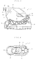
- FIG. 3 is a plan view of the lever-type connector of FIG. 1 .
- FIG. 4 is a side view of one side in the left-and-right direction of the lever-type connector of FIG. 1 .
- FIG. 1 is a perspective view illustrative of the top surface side and one side in the left-and-right direction of a lever-type connector according to the embodiment of the present invention.
- FIG. 2 is a perspective view illustrative of the bottom surface side and the other side in the left-and-right direction of the lever-type connector of FIG. 1 .
- FIG. 3 is a plan view of the lever-type connector of FIG.
- FIG. 5 is a side view of the other side in the left-and-right direction of the lever-type connector of FIG. 1 .
- FIG. 6 is a back view of the lever-type connector of FIG. 1 .
- FIG. 7 is a perspective view of the lever-type connector of FIG. 1 in a disassembled state.
- FIG. 8 is an enlarged rear view illustrative of an end of a lever provided to the lever-type connector of FIG. 1 .
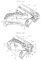
- FIG. 9 is a perspective view illustrative of the top and one side in the left-and-right direction in a state midway through attaching a wire cover to a housing.
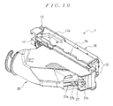
- FIG. 10 is a perspective view illustrative of the bottom and the other side in the left-and-right direction in a state midway through attaching the wire cover to the housing.
- FIG. 11 is a perspective view illustrative of a state where attachment of the wire cover to the housing is completed, and a lever is not attached.
- FIG. 12 is a perspective view illustrative of a state midway through sandwiching the rear surface side of the wire cover by both side plates of the lever.
- FIG. 13 is a perspective view illustrative of a state where the rear surface side of the wire cover is sandwiched by both side plates of the lever.
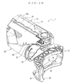
- FIG. 14 is a perspective view illustrative of a state where assembly of the lever-type connecter is completed.
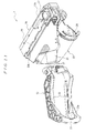
- FIG. 15 is a perspective view illustrative of a state midway through removing the lever from the wire cover.
- FIG. 16 is a perspective view illustrative of a state where removal of the lever from the wire cover is completed.
- FIG. 17 is a perspective view illustrative of a state midway through reattaching the lever to the wire cover.
- FIG. 18 is a plan view illustrative of a lever-type connector in a state where a lever is turned to a final position on the rear side.
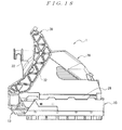
- FIG. 19 is a plan view illustrative of a lever-type connector in a state where a lever is turned to a final position on the front side.
- FIG. 20 is a cross-sectional view of the lever-type connector of FIG. 19 .
- the lever-type connector 1 shown in FIGS. 1 to 7 includes a housing 10, which accommodates multiple contacts (not illustrated in the drawings), a wire cover 20, which is attached to the rear surface side (upper side in FIG. 3 ) of the housing 10, and a lever 30, which is attached to the housing 10.
- the housing 10 is formed extending in the left-and-right direction (left-and-right direction in FIG. 3 ), and has multiple contact receiving holes 11, which pass through in the front-and-rear direction (up-and-down direction in FIG. 3 ), as shown in FIG. 7 .
- a slider accommodating slot 12 extending in the left-and-right direction on either inner surface of the housing 10 in the up-and-down direction (up-and-down direction in FIG.
- a slider 13 is accommodated in each of the sliding accommodating slots 12 so as to move freely in the left-and-right direction.
- a pair of pivot receiving portions 16 respectively join to a pivot 34 described later of the lever 30 is provided on an end in the left-and-right direction of the housing 10.
- a latch arm 16a for locking the pivot 34 of the lever joined to each of the pivot receiving portions 16 is provided at the rear of each of the bearings of the housing 10.
- Fixed pieces 17 for fixing the wire cover 20 are provided on either end in the left-and-right direction of the rear surface of the housing, as shown in FIG. 7 . Both of the fixed pieces 17 are provided protruding toward the rear, extending in the left-and-right direction.
- Multiple (four in this embodiment) fixing projection portions 17a which protrude toward the outside, are provided in the left-and-right direction on the outer side surface in the left-and-right direction of each of the fixed pieces 17.
- Each of the sliders 13 is formed in a plate shape, extending in the left-and-right direction.
- Multiple cam grooves (not illustrated in the drawings), which lead in and push out cam pins (not illustrated in the drawings) provided on a mating connector, are provided in the left-and-right direction of the inner surface of each of the sliders 13.
- projection receiving portions 15 respectively joined to a slider moving projection 35 described later of the lever 30 are each provided on an end in the left-and-right direction of each of the sliders 13.
- the lever 30 is formed in a U shape and includes a connecting part 33 for connecting a pair of side plates 32 extending in the left-and-right direction and connecting the other ends of both of the side plates 32 to each other.
- the slider moving projection 35 which joins to the projection receiving portion 15 of each of the sliders 13, is formed protruding outward on the outer surface of an end of both of the side plates 32, as shown in FIG. 7 and FIG. 8 .
- the pivot 34 which joins to each of the pivot receiving portions 16 of the housing 10, is provided protruding inward on the inner surface of the end of both of the side plates 32.
- connecting plates 37 each extending inward are provided on the inner surface of the end of both of the side plates 32, as shown in FIG. 8 .
- Respective ends of both of the side plates 32 are joined to each other by a depression 37a provided at the end of the connecting plate 37 of one of the side plates 32 and a projection 37b provided on end of connecting plate 37 of the other side plate 32.
- a flat part 38 which makes contact with a slant face 50a described later of the wire cover 20 when removing the lever 30 from the housing 10, is formed on the inner surface on an end side of each of the side plates 32.
- notches 39 each extending in the left-and-right direction are provided on the inner surface of both of the side plates 32.
- the wire cover 20 includes a main body 21, which covers electrical wires (not illustrated in the drawings) connected to the contacts accommodated in the housing 10, a deterring section 22, which is provided on a side in the left-to-right direction of the main body 21, and a first tapered portion 50, which is formed between the main body 21 and the deterring section 22. Thickness in the up-and-down direction of the main body 21 is less than distance between both of the side plates 32 of the lever 30.
- the deterring section 22 deters the lever 30 that has been rotated until the final position (see FIG. 18 ) at the rear from rotating further toward the rear.
- the first tapered portion 50 includes a slanted face 50a, which continues to the top surface of the main body 21 and the top surface of the ceterring section 22, and a slated face 50b, which continues to the bottom surface of the main body 21 and the bottom surface of the deterring section 22.
- the lock member 27 which prevents the lever 30 that has been rotated until the final position (see FIG. 19 and FIG. 20 ) on the front side from rotating toward the rear side, is provided on the rear surface of the main body 21.
- the lock member 27 is formed in a cantilever plate-spring form and extends from the rear side toward the front side of the connecting part 33 of the lever 30 positioned at the final position on the front side.
- the lock member 27 has a plate spring 27a, and a lock piece 27b and a release projection portion 27c provided on the outer surface of the plate spring 27a.
- the plate spring 27a is provided extending from the rear toward the front of the connecting part 33 of the lever 30 positioned at the final position on the front side.
- the lock piece 27b is provided for latching onto the depression 33a of the connecting part 33 of the lever 30 positioned at the final position on the front side.
- the release projection portion 27c is provided so as to be positioned on the front side of the connecting part 33 of the lever 30 positioned at the final position on the front side.
- Each of the lock projection portions 28 is provided for latching onto the sides of the notches 39 of each of the side plates 32 of the lever 30 positioned at the final position on the rear side.
- Fixed parts 29 for fixing the wire cover 20 to the housing 10 are provided on the front end of the top surface and the front end of the bottom surface of the main body 21, as shown in FIG. 7 . Both of the fixed parts 29 are provided extending in the left-and-right direction. Both of the fixed parts 29 are provided so as to protrude outward in the up-and-down direction.
- a fixing groove 29a into which the fixing projection portions 17a of the housing 10 are inserted is provided to the respective inner surfaces of the fixed parts 29 in the left-and-right direction.
- a latch arm 29b is provided on the other end in the left-and-right direction of each of the fixed parts 29. Projections (not illustrated in the drawings) for latching onto the side of the fixing projection portions 17a of the housing 10 are provided on each of the latch arms 29.
- a second tapered portion 51 which has a thickness in the up-and-down direction that gradually decreases toward the outer side, is formed on the rear surface of the main body 21.
- the wire cover 20 is attached to the housing 10 which accommodates the multiple contacts.
- the wire cover 20 arranged on the rear side of the housing 10 is slid from one side to the other side in the left-and-right direction of the housing 10, as shown in FIG. 9 and FIG. 10 .
- the multiple fixing projection portions 17a of both of the fixed pieces 17 of the housing 10 are inserted into the fixing grooves 29a of each of the fixed parts 29 of the wire cover 20.
- the multiple fixing projection portions 17a are inserted into the fixing grooves 29a from one side in the left-and-right direction of the fixing grooves 29a in order from those on the other side in the left-and-right direction.
- the projections which are provided on the latch arms 29b of the fixed parts 29, latching onto the sides on the other side in the left-and-right direction of the fixing projection portions 17a provided furthest on the other side in the left-and-right direction locks the wire cover 20.
- the bound, electrical wires connected to the multiple contacts accommodated in the housing 10 are lead out from the electrical wire outlet 24 of the wire cover 20.
- the lever 30 is then attached to the housing 10 to which the wire cover 20 is attached.
- the lever 30 When attaching the lever 30 to the housing 10 to which the wire cover 20 is attached, the lever 30 must be arranged in the wire cover 20 so as for both of the side plates 32 to bridge over the rear surface side of the wire cover 20 and sandwich the wire cover 20 in the up-and-down direction (thickness direction). Accordingly, when attaching the lever 30 to the housing 10, as shown in FIG. 11 , the ends of both of the side plates 32 of the lever 30 are first spread manually, and the distance between the ends of the connecting plates 37 of both of the side plates 32 is one allowing insertion of the edge of the second tapered portion 51 of the wire cover 20. In the state where the ends of both of the side plates 32 of the lever 30 are spread manually, the edge of the second tapered portion 51 of the wire cover 20 is inserted into between the ends of both of the connecting plates 37.
- the ends of both of the side plates 32 should be spread such that the distance between the ends of the connecting plates 37 of both of the side plates 32 is one allowing insertion of the edge of the second tapered portion 51 of the wire cover 20.
- the second tapered portion 51 of the wire cover 20 pushes apart the ends of both of the side plates 32 of the lever 30 such that the distance between the ends of the connecting plates 37 of both of the side plates 32 is equivalent to thickness in the up-and-down direction of the main body 21 of the wire cover 20.
- the thickness of the end of the second tapered portion 51 of the wire cover 20 in the up-and-down direction is formed sufficiently less than that of the main body 21 in the up-and-down direction. Accordingly, when a worker attaches the lever 30, both of the side plates 32 do not need to be spread until the distance between the ends of the connecting plates 37 of both of the side plates 32 is greater than thickness of the main body 21 of the wire cover 20 in the up-and-down direction. Moreover, the lever 30 is formed such that the distance between the connecting plates 37 of both of the side plates 32 is equivalent to thickness of the wire cover 20 of the main body 21 in the up-and-down direction so as to be strong enough that it does not break the connecting part 33 even if it deforms it.
- lever-type connector 1 when attaching the lever 30 to the housing 10, excess spreading of the end of the lever 30 by the worker may be prevented, and thereby preventing damage to the lever 30. Operation when replacing a contact of the lever-type connector 1 will be described next.
- the lever-type connector 1 it is necessary to remove the wire cover 20 from the housing 10 so as to expose the contact accommodated in the housing 10 in order to replace the contact.
- the lever-type connector 1 in order to remove the wire cover 20 from the housing 10, it is necessary to remove the lever 30, which is arranged bridging the rear surface side of the wire cover 20, from the wire cover 20.
- the lever 30 When replacing a contact of the lever-type connector 1, the lever 30 is first removed from the wire cover 20 of the lever-type connector 1 in the assembled state shown in FIG. 14 .
- the pivots 34 of both of the side plates 32 of the lever 30 are first removed from each of the bearings 16 of the housing 10, as shown in FIG. 13 .
- the slider moving projections 35 of both of the side plates 32 of the lever 30 are then removed from the projection receiving portions 15 of each of the sliders 13.
- the lever 30 is pushed in to move the ends of both of the side plates 32 toward the rear side of the wire cover 20.
- the flat portions 38 of both of the side plates 32 make contact with the second tapered portion 50 of the wire cover 20.
- the flat portions 38 of both of the side plates 32 move along the slanted faces 50a and 50b of the first tapered portion 50 of the wire cover 20, as shown in FIG. 15 .
- the first tapered portion 50 of the wire cover 20 then pushes apart the ends of both of the side plates 32 of the lever 30.
- the first tapered portion 50 continuing to the main body 21 is formed on the deterring section 22 in this manner. Therefore, the worker does not need to spread the ends of both of the side plates 32 when removing the lever 30 from the housing 10. Namely, the worker pushes the lever 30 in toward the rear of the wire cover 20, making the first tapered portion 50 of the wire cover 20 push apart the ends of both of the side plates 32 such that the distance between both of the side plates 32 is equivalent to thickness of the stopper 22 of the wire cover 20 in the up-and-down direction.
- the wire cover 20 is reattached to the housing 10 in the aforementioned sequence.
- the lever 30 is then reattached to the housing 10 to which the wire cover 20 is mounted.
- the notches 39 of both of the side plates 32 of the lever 30 are brought into contact with the outer surface of the hood portion 25 of the deterring section 22 on the wire cover 20.
- the lever 30 is pushed inward so as to move the notches 39 of both of the side plates 32 of the lever 30 toward the front of the wire cover.
- the worker pushes the lever 30 in toward the front of the wire cover 20, making the hood 25 of the deterring section 22 of the wire cover 20 push apart the ends of both of the side plates 32 such that the distance between both of the side plates 32 is equivalent to thickness of the deterring section 22 of the wire cover 20 in the up-and-down direction.
- lever-type connector 1 when reattaching the lever 30 to the housing 10, excess spreading of the end of the lever 30 by the worker may be prevented, and thereby preventing damage to the lever 30.
- Mechanism of the lever-type connector 1 will now be described. With the lever-type connector 1 in the assembled state shown in FIG. 14 , if the lever 30 is rotated toward the front, the sliders 13 are moved in the direction of going into the slider accommodating slot 12 of the housing 10. Moreover, if the lever 30 is rotated toward the rear, the sliders 13 are moved in the direction of coming out from the slider accommodating slot 12 of the housing 10.
- the lever 30 When mating the lever-type connector 1 to a mating connector, the lever 30 is first brought into a state of being rotated until the final position on the rear side, as shown in FIG. 18 .
- the lever 30 that is rotated until the final position on the rear side is in a state unable to be rotated any further toward the rear by the deterring section 22.
- the lever 30 that has been rotated until the final position on the rear side is in a state where rotation toward the front is intercepted by the lock projection portion 28 of the main body 21 of the wire cover 20 latching onto the sides of the notches 39 of both of the side plates of the lever 30.
- the sliders 13 are moved in the direction of coming out from the slider accommodating slot 12 of the housing 10 so as to allow insertion of cam pins provided on the mating connector into cam grooves of the sliders 13.
- a lever-type connector according to a first aspect of the present invention prevents a worker from damaging a lever when removing the lever from a housing. Moreover, a lever-type connector according to a second aspect of the present invention prevents a worker from damaging a lever when attaching the lever to a housing.
Applications Claiming Priority (2)
| Application Number | Priority Date | Filing Date | Title |
|---|---|---|---|
| JP2008087616A JP4468465B2 (ja) | 2008-03-28 | 2008-03-28 | レバー式コネクタ |
| PCT/JP2009/055274 WO2009119403A1 (ja) | 2008-03-28 | 2009-03-18 | レバー式コネクタ |
Publications (3)
| Publication Number | Publication Date |
|---|---|
| EP2276121A1 true EP2276121A1 (de) | 2011-01-19 |
| EP2276121A4 EP2276121A4 (de) | 2013-05-15 |
| EP2276121B1 EP2276121B1 (de) | 2015-09-09 |
Family
ID=41113600
Family Applications (1)
| Application Number | Title | Priority Date | Filing Date |
|---|---|---|---|
| EP09724788.6A Active EP2276121B1 (de) | 2008-03-28 | 2009-03-18 | Verbinder des hebeltyps |
Country Status (5)
| Country | Link |
|---|---|
| US (1) | US8057245B2 (de) |
| EP (1) | EP2276121B1 (de) |
| JP (1) | JP4468465B2 (de) |
| CN (2) | CN101981761B (de) |
| WO (1) | WO2009119403A1 (de) |
Families Citing this family (22)
| Publication number | Priority date | Publication date | Assignee | Title |
|---|---|---|---|---|
| CN102084555A (zh) * | 2008-05-06 | 2011-06-01 | 莫列斯公司 | 杠杆型电连接器 |
| JP4523987B1 (ja) * | 2009-02-27 | 2010-08-11 | タイコエレクトロニクスジャパン合同会社 | スライドカム付きコネクタ |
| JP5407959B2 (ja) * | 2010-03-17 | 2014-02-05 | 住友電装株式会社 | コネクタ |
| JP5343902B2 (ja) * | 2010-03-17 | 2013-11-13 | 住友電装株式会社 | コネクタ |
| JP5407960B2 (ja) * | 2010-03-17 | 2014-02-05 | 住友電装株式会社 | レバー式コネクタ |
| JP5588773B2 (ja) * | 2010-07-28 | 2014-09-10 | タイコエレクトロニクスジャパン合同会社 | ワイヤカバー、電気コネクタ |
| JP5624874B2 (ja) * | 2010-12-24 | 2014-11-12 | タイコエレクトロニクスジャパン合同会社 | レバー式コネクタ、ワイヤカバー |
| JP5968605B2 (ja) * | 2011-08-29 | 2016-08-10 | タイコエレクトロニクスジャパン合同会社 | レバーを備えたコネクタおよび電線カバー |
| US9142916B2 (en) * | 2013-03-15 | 2015-09-22 | Tyco Electronics Corporation | Connector assembly with receptacle carriers |
| KR101503507B1 (ko) * | 2014-04-09 | 2015-03-18 | 주식회사 경신 | 차량용 커넥터 |
| JP6339873B2 (ja) * | 2014-06-27 | 2018-06-06 | モレックス エルエルシー | コネクタ |
| JP2016207414A (ja) * | 2015-04-21 | 2016-12-08 | 住友電装株式会社 | コネクタ |
| FR3044173B1 (fr) * | 2015-11-20 | 2019-05-17 | Aptiv Technologies Limited | Connecteur avec coulisseau d'assistance a la connexion et capot guide-cable |
| JP6275104B2 (ja) * | 2015-12-11 | 2018-02-07 | 矢崎総業株式会社 | コネクタ構造 |
| JP6222588B1 (ja) * | 2016-10-14 | 2017-11-01 | 住友電装株式会社 | レバー式コネクタ |
| JP2018181575A (ja) * | 2017-04-12 | 2018-11-15 | タイコエレクトロニクスジャパン合同会社 | 電気コネクタ |
| EP3392979B1 (de) * | 2017-04-19 | 2020-01-29 | Aptiv Technologies Limited | Elektrischer stecker mit hebel und montage verfharen dafür |
| JP6564815B2 (ja) * | 2017-06-26 | 2019-08-21 | 矢崎総業株式会社 | コネクタ |
| JP6912443B2 (ja) * | 2018-11-29 | 2021-08-04 | 矢崎総業株式会社 | 電線固定構造、電気接続箱、及びワイヤハーネス |
| JP7183871B2 (ja) * | 2019-03-05 | 2022-12-06 | 住友電装株式会社 | レバー式コネクタ |
| JP7021150B2 (ja) * | 2019-05-27 | 2022-02-16 | 矢崎総業株式会社 | レバー式コネクタ及びレバー式コネクタの組み付け方法 |
| JP7249506B2 (ja) * | 2019-10-18 | 2023-03-31 | 株式会社オートネットワーク技術研究所 | レバー式コネクタ |
Citations (2)
| Publication number | Priority date | Publication date | Assignee | Title |
|---|---|---|---|---|
| EP1677392A1 (de) * | 2004-12-28 | 2006-07-05 | Sumitomo Wiring Systems, Ltd. | Modularer Verbinder und Verfahren zu seiner Zusammenstellung |
| WO2007044393A2 (en) * | 2005-10-06 | 2007-04-19 | Fci Americas Technology, Inc. | Electrical connector |
Family Cites Families (29)
| Publication number | Priority date | Publication date | Assignee | Title |
|---|---|---|---|---|
| JP2762896B2 (ja) * | 1993-06-14 | 1998-06-04 | 住友電装株式会社 | レバー式コネクタ |
| FR2717627B1 (fr) * | 1994-03-21 | 1996-04-26 | Cinch Connecteurs Sa | Dispositif d'accouplement de deux éléments de boîtier d'un connecteur électrique. |
| EP0820647B1 (de) * | 1995-04-12 | 1999-07-28 | The Whitaker Corporation | Modularer elektrischer steckverbinder |
| US6039586A (en) * | 1996-09-06 | 2000-03-21 | The Whitaker Corporation | Lever type connector |
| US6270376B1 (en) * | 1998-02-19 | 2001-08-07 | Delphi Technologies, Inc. | Pre-staged dual lock multi-row electrical connection system |
| JP3252955B2 (ja) * | 1998-05-21 | 2002-02-04 | 住友電装株式会社 | レバー式コネクタ |
| US5938458A (en) * | 1998-06-17 | 1999-08-17 | Molex Incorporated | Lever type electrical connector |
| IT1303186B1 (it) * | 1998-11-27 | 2000-10-30 | Framatome Connectors Italia | Connettore elettrico. |
| US6305957B1 (en) * | 2000-02-24 | 2001-10-23 | Delphi Technologies, Inc. | Electrical connector assembly |
| US6217354B1 (en) * | 2000-03-20 | 2001-04-17 | Molek Incorporated | Lever type electrical connector |
| US6666698B2 (en) * | 2000-08-17 | 2003-12-23 | Tyco Electronics Corporation | Arc limiting electrical connector assembly |
| JP3492309B2 (ja) * | 2000-11-02 | 2004-02-03 | エフシーアイジャパン株式会社 | コネクタ |
| DE10057428B4 (de) * | 2000-11-20 | 2006-05-18 | Ria-Btr Produktions-Gmbh | Anschlußklemme |
| US6896531B2 (en) * | 2001-02-27 | 2005-05-24 | Delphi Technologies, Inc. | Electrical connector assembly |
| ITTO20010290A1 (it) * | 2001-03-27 | 2002-09-27 | Framatome Connectors Italia | Connetore elettrico. |
| FR2830133A1 (fr) * | 2001-09-24 | 2003-03-28 | Framatome Connectors Int | Connecteur a dispositif d'aide a l'accouplement |
| US6682359B1 (en) * | 2002-12-06 | 2004-01-27 | Tyco Electronics Corporation | Electrical connector assembly with connection assurance features |
| US20040192090A1 (en) * | 2003-03-28 | 2004-09-30 | Flowers Robert J. | Lever type electrical connector with CPA member |
| US7070438B2 (en) * | 2004-03-31 | 2006-07-04 | Jst Corporation | Connector lever lock |
| US6899554B1 (en) * | 2004-04-19 | 2005-05-31 | Jst Corporation | Dual action mechanical assisted connector |
| JP2006147492A (ja) | 2004-11-24 | 2006-06-08 | Sumitomo Wiring Syst Ltd | コネクタ |
| DE102004061531A1 (de) * | 2004-12-21 | 2006-06-29 | Fci | Steckverbinder mit Verriegelungsbügel mit erleichterter Montage |
| ITTO20050089A1 (it) * | 2005-02-16 | 2006-08-17 | Fci Italia S P A | Connettore elettrico |
| JP4478060B2 (ja) * | 2005-04-08 | 2010-06-09 | 矢崎総業株式会社 | カバー付コネクタ |
| JP2006324227A (ja) * | 2005-04-18 | 2006-11-30 | Yazaki Corp | コネクタ |
| SG135994A1 (en) * | 2006-03-17 | 2007-10-29 | J S T Mfg Co Ltd | Electric connector |
| DE102006058680A1 (de) * | 2006-12-13 | 2008-06-19 | Kostal Kontakt Systeme Gmbh | Elektrischer Steckverbinder |
| JP4944052B2 (ja) * | 2008-02-08 | 2012-05-30 | 矢崎総業株式会社 | レバー嵌合式コネクタ |
| JP4387438B2 (ja) * | 2008-03-28 | 2009-12-16 | タイコエレクトロニクスアンプ株式会社 | レバー式コネクタ |
-
2008
- 2008-03-28 JP JP2008087616A patent/JP4468465B2/ja active Active
-
2009
- 2009-03-18 WO PCT/JP2009/055274 patent/WO2009119403A1/ja active Application Filing
- 2009-03-18 CN CN2009801124831A patent/CN101981761B/zh active Active
- 2009-03-18 EP EP09724788.6A patent/EP2276121B1/de active Active
- 2009-03-18 CN CN201310077704.4A patent/CN103178397B/zh active Active
-
2010
- 2010-09-28 US US12/892,284 patent/US8057245B2/en active Active
Patent Citations (2)
| Publication number | Priority date | Publication date | Assignee | Title |
|---|---|---|---|---|
| EP1677392A1 (de) * | 2004-12-28 | 2006-07-05 | Sumitomo Wiring Systems, Ltd. | Modularer Verbinder und Verfahren zu seiner Zusammenstellung |
| WO2007044393A2 (en) * | 2005-10-06 | 2007-04-19 | Fci Americas Technology, Inc. | Electrical connector |
Non-Patent Citations (1)
| Title |
|---|
| See also references of WO2009119403A1 * |
Also Published As
| Publication number | Publication date |
|---|---|
| EP2276121B1 (de) | 2015-09-09 |
| JP4468465B2 (ja) | 2010-05-26 |
| WO2009119403A1 (ja) | 2009-10-01 |
| CN103178397B (zh) | 2015-05-13 |
| US8057245B2 (en) | 2011-11-15 |
| JP2009245608A (ja) | 2009-10-22 |
| CN103178397A (zh) | 2013-06-26 |
| CN101981761A (zh) | 2011-02-23 |
| EP2276121A4 (de) | 2013-05-15 |
| US20110014804A1 (en) | 2011-01-20 |
| CN101981761B (zh) | 2013-09-11 |
Similar Documents
| Publication | Publication Date | Title |
|---|---|---|
| EP2276121B1 (de) | Verbinder des hebeltyps | |
| EP2276123B1 (de) | Verbinder des hebeltyps | |
| EP2276122B1 (de) | Verbinder des hebeltyps | |
| EP1672747B1 (de) | Verbinder | |
| EP2224549B1 (de) | Hebelsteckverbinder, Steckverbinderanordnung und Verbindungsverfahren | |
| JP4688113B2 (ja) | コネクタ位置保証装置を有するレバー嵌合型コネクタ組立体 | |
| EP2658041B1 (de) | Hebelsteckverbinder | |
| EP1742302B1 (de) | Verbinder, Verbindungseinrichtung und Montageverfahren dafür | |
| EP2278667A1 (de) | Verbinder des hebeltyps | |
| JP3275290B2 (ja) | レバー式コネクタ | |
| US20100081313A1 (en) | Lever-Type Connector | |
| JP2008510281A (ja) | レバー式機械補助付きコネクタ | |
| JP5172871B2 (ja) | レバー式コネクタ | |
| US20080064242A1 (en) | Lever Type Electrical Connector | |
| JPH11273787A (ja) | コネクタ | |
| JP5052322B2 (ja) | レバー式コネクタ | |
| JP3494285B2 (ja) | コネクタ | |
| KR100920098B1 (ko) | 레버식 커넥터 | |
| JP2004103557A (ja) | レバー式嵌合コネクタ | |
| CN111052515B (zh) | 用于至少两个电导体的自动联接的插接连接装置 | |
| JP2008262718A (ja) | コネクタ | |
| CN111834788A (zh) | 带有端子锁的电端子壳体 | |
| EP2557638B1 (de) | Hebelartiger Stecker und Verfahren zu dessen Montage | |
| JP4158912B2 (ja) | パネル取付用レバー式嵌合コネクタ | |
| JP3770454B2 (ja) | コネクタ組立体 |
Legal Events
| Date | Code | Title | Description |
|---|---|---|---|
| PUAI | Public reference made under article 153(3) epc to a published international application that has entered the european phase |
Free format text: ORIGINAL CODE: 0009012 |
|
| 17P | Request for examination filed |
Effective date: 20101021 |
|
| AK | Designated contracting states |
Kind code of ref document: A1 Designated state(s): AT BE BG CH CY CZ DE DK EE ES FI FR GB GR HR HU IE IS IT LI LT LU LV MC MK MT NL NO PL PT RO SE SI SK TR |
|
| AX | Request for extension of the european patent |
Extension state: AL BA RS |
|
| DAX | Request for extension of the european patent (deleted) | ||
| A4 | Supplementary search report drawn up and despatched |
Effective date: 20130416 |
|
| RIC1 | Information provided on ipc code assigned before grant |
Ipc: H01R 13/629 20060101AFI20130410BHEP Ipc: H01R 13/516 20060101ALI20130410BHEP |
|
| 17Q | First examination report despatched |
Effective date: 20140310 |
|
| GRAP | Despatch of communication of intention to grant a patent |
Free format text: ORIGINAL CODE: EPIDOSNIGR1 |
|
| INTG | Intention to grant announced |
Effective date: 20150409 |
|
| GRAS | Grant fee paid |
Free format text: ORIGINAL CODE: EPIDOSNIGR3 |
|
| GRAA | (expected) grant |
Free format text: ORIGINAL CODE: 0009210 |
|
| AK | Designated contracting states |
Kind code of ref document: B1 Designated state(s): AT BE BG CH CY CZ DE DK EE ES FI FR GB GR HR HU IE IS IT LI LT LU LV MC MK MT NL NO PL PT RO SE SI SK TR |
|
| REG | Reference to a national code |
Ref country code: GB Ref legal event code: FG4D |
|
| REG | Reference to a national code |
Ref country code: AT Ref legal event code: REF Ref document number: 748814 Country of ref document: AT Kind code of ref document: T Effective date: 20150915 Ref country code: CH Ref legal event code: EP |
|
| REG | Reference to a national code |
Ref country code: IE Ref legal event code: FG4D |
|
| REG | Reference to a national code |
Ref country code: DE Ref legal event code: R096 Ref document number: 602009033516 Country of ref document: DE |
|
| REG | Reference to a national code |
Ref country code: NL Ref legal event code: MP Effective date: 20150909 |
|
| PG25 | Lapsed in a contracting state [announced via postgrant information from national office to epo] |
Ref country code: LT Free format text: LAPSE BECAUSE OF FAILURE TO SUBMIT A TRANSLATION OF THE DESCRIPTION OR TO PAY THE FEE WITHIN THE PRESCRIBED TIME-LIMIT Effective date: 20150909 Ref country code: FI Free format text: LAPSE BECAUSE OF FAILURE TO SUBMIT A TRANSLATION OF THE DESCRIPTION OR TO PAY THE FEE WITHIN THE PRESCRIBED TIME-LIMIT Effective date: 20150909 Ref country code: NO Free format text: LAPSE BECAUSE OF FAILURE TO SUBMIT A TRANSLATION OF THE DESCRIPTION OR TO PAY THE FEE WITHIN THE PRESCRIBED TIME-LIMIT Effective date: 20151209 Ref country code: LV Free format text: LAPSE BECAUSE OF FAILURE TO SUBMIT A TRANSLATION OF THE DESCRIPTION OR TO PAY THE FEE WITHIN THE PRESCRIBED TIME-LIMIT Effective date: 20150909 Ref country code: GR Free format text: LAPSE BECAUSE OF FAILURE TO SUBMIT A TRANSLATION OF THE DESCRIPTION OR TO PAY THE FEE WITHIN THE PRESCRIBED TIME-LIMIT Effective date: 20151210 |
|
| REG | Reference to a national code |
Ref country code: LT Ref legal event code: MG4D |
|
| REG | Reference to a national code |
Ref country code: AT Ref legal event code: MK05 Ref document number: 748814 Country of ref document: AT Kind code of ref document: T Effective date: 20150909 |
|
| PG25 | Lapsed in a contracting state [announced via postgrant information from national office to epo] |
Ref country code: ES Free format text: LAPSE BECAUSE OF FAILURE TO SUBMIT A TRANSLATION OF THE DESCRIPTION OR TO PAY THE FEE WITHIN THE PRESCRIBED TIME-LIMIT Effective date: 20150909 Ref country code: HR Free format text: LAPSE BECAUSE OF FAILURE TO SUBMIT A TRANSLATION OF THE DESCRIPTION OR TO PAY THE FEE WITHIN THE PRESCRIBED TIME-LIMIT Effective date: 20150909 Ref country code: SE Free format text: LAPSE BECAUSE OF FAILURE TO SUBMIT A TRANSLATION OF THE DESCRIPTION OR TO PAY THE FEE WITHIN THE PRESCRIBED TIME-LIMIT Effective date: 20150909 |
|
| REG | Reference to a national code |
Ref country code: FR Ref legal event code: PLFP Year of fee payment: 8 |
|
| PG25 | Lapsed in a contracting state [announced via postgrant information from national office to epo] |
Ref country code: NL Free format text: LAPSE BECAUSE OF FAILURE TO SUBMIT A TRANSLATION OF THE DESCRIPTION OR TO PAY THE FEE WITHIN THE PRESCRIBED TIME-LIMIT Effective date: 20150909 |
|
| PG25 | Lapsed in a contracting state [announced via postgrant information from national office to epo] |
Ref country code: CZ Free format text: LAPSE BECAUSE OF FAILURE TO SUBMIT A TRANSLATION OF THE DESCRIPTION OR TO PAY THE FEE WITHIN THE PRESCRIBED TIME-LIMIT Effective date: 20150909 Ref country code: IT Free format text: LAPSE BECAUSE OF FAILURE TO SUBMIT A TRANSLATION OF THE DESCRIPTION OR TO PAY THE FEE WITHIN THE PRESCRIBED TIME-LIMIT Effective date: 20150909 Ref country code: EE Free format text: LAPSE BECAUSE OF FAILURE TO SUBMIT A TRANSLATION OF THE DESCRIPTION OR TO PAY THE FEE WITHIN THE PRESCRIBED TIME-LIMIT Effective date: 20150909 Ref country code: IS Free format text: LAPSE BECAUSE OF FAILURE TO SUBMIT A TRANSLATION OF THE DESCRIPTION OR TO PAY THE FEE WITHIN THE PRESCRIBED TIME-LIMIT Effective date: 20160109 Ref country code: SK Free format text: LAPSE BECAUSE OF FAILURE TO SUBMIT A TRANSLATION OF THE DESCRIPTION OR TO PAY THE FEE WITHIN THE PRESCRIBED TIME-LIMIT Effective date: 20150909 |
|
| PG25 | Lapsed in a contracting state [announced via postgrant information from national office to epo] |
Ref country code: RO Free format text: LAPSE BECAUSE OF FAILURE TO SUBMIT A TRANSLATION OF THE DESCRIPTION OR TO PAY THE FEE WITHIN THE PRESCRIBED TIME-LIMIT Effective date: 20150909 Ref country code: PT Free format text: LAPSE BECAUSE OF FAILURE TO SUBMIT A TRANSLATION OF THE DESCRIPTION OR TO PAY THE FEE WITHIN THE PRESCRIBED TIME-LIMIT Effective date: 20160111 Ref country code: PL Free format text: LAPSE BECAUSE OF FAILURE TO SUBMIT A TRANSLATION OF THE DESCRIPTION OR TO PAY THE FEE WITHIN THE PRESCRIBED TIME-LIMIT Effective date: 20150909 Ref country code: AT Free format text: LAPSE BECAUSE OF FAILURE TO SUBMIT A TRANSLATION OF THE DESCRIPTION OR TO PAY THE FEE WITHIN THE PRESCRIBED TIME-LIMIT Effective date: 20150909 |
|
| REG | Reference to a national code |
Ref country code: DE Ref legal event code: R097 Ref document number: 602009033516 Country of ref document: DE |
|
| PLBE | No opposition filed within time limit |
Free format text: ORIGINAL CODE: 0009261 |
|
| STAA | Information on the status of an ep patent application or granted ep patent |
Free format text: STATUS: NO OPPOSITION FILED WITHIN TIME LIMIT |
|
| 26N | No opposition filed |
Effective date: 20160610 |
|
| PG25 | Lapsed in a contracting state [announced via postgrant information from national office to epo] |
Ref country code: DK Free format text: LAPSE BECAUSE OF FAILURE TO SUBMIT A TRANSLATION OF THE DESCRIPTION OR TO PAY THE FEE WITHIN THE PRESCRIBED TIME-LIMIT Effective date: 20150909 Ref country code: BE Free format text: LAPSE BECAUSE OF NON-PAYMENT OF DUE FEES Effective date: 20160331 Ref country code: SI Free format text: LAPSE BECAUSE OF FAILURE TO SUBMIT A TRANSLATION OF THE DESCRIPTION OR TO PAY THE FEE WITHIN THE PRESCRIBED TIME-LIMIT Effective date: 20150909 |
|
| PG25 | Lapsed in a contracting state [announced via postgrant information from national office to epo] |
Ref country code: MC Free format text: LAPSE BECAUSE OF FAILURE TO SUBMIT A TRANSLATION OF THE DESCRIPTION OR TO PAY THE FEE WITHIN THE PRESCRIBED TIME-LIMIT Effective date: 20150909 Ref country code: LU Free format text: LAPSE BECAUSE OF FAILURE TO SUBMIT A TRANSLATION OF THE DESCRIPTION OR TO PAY THE FEE WITHIN THE PRESCRIBED TIME-LIMIT Effective date: 20160318 |
|
| REG | Reference to a national code |
Ref country code: CH Ref legal event code: PL |
|
| REG | Reference to a national code |
Ref country code: IE Ref legal event code: MM4A |
|
| PG25 | Lapsed in a contracting state [announced via postgrant information from national office to epo] |
Ref country code: BE Free format text: LAPSE BECAUSE OF FAILURE TO SUBMIT A TRANSLATION OF THE DESCRIPTION OR TO PAY THE FEE WITHIN THE PRESCRIBED TIME-LIMIT Effective date: 20150909 |
|
| PG25 | Lapsed in a contracting state [announced via postgrant information from national office to epo] |
Ref country code: CH Free format text: LAPSE BECAUSE OF NON-PAYMENT OF DUE FEES Effective date: 20160331 Ref country code: IE Free format text: LAPSE BECAUSE OF NON-PAYMENT OF DUE FEES Effective date: 20160318 Ref country code: LI Free format text: LAPSE BECAUSE OF NON-PAYMENT OF DUE FEES Effective date: 20160331 |
|
| REG | Reference to a national code |
Ref country code: FR Ref legal event code: PLFP Year of fee payment: 9 |
|
| PG25 | Lapsed in a contracting state [announced via postgrant information from national office to epo] |
Ref country code: MT Free format text: LAPSE BECAUSE OF FAILURE TO SUBMIT A TRANSLATION OF THE DESCRIPTION OR TO PAY THE FEE WITHIN THE PRESCRIBED TIME-LIMIT Effective date: 20150909 |
|
| REG | Reference to a national code |
Ref country code: FR Ref legal event code: PLFP Year of fee payment: 10 |
|
| PG25 | Lapsed in a contracting state [announced via postgrant information from national office to epo] |
Ref country code: CY Free format text: LAPSE BECAUSE OF FAILURE TO SUBMIT A TRANSLATION OF THE DESCRIPTION OR TO PAY THE FEE WITHIN THE PRESCRIBED TIME-LIMIT Effective date: 20150909 Ref country code: HU Free format text: LAPSE BECAUSE OF FAILURE TO SUBMIT A TRANSLATION OF THE DESCRIPTION OR TO PAY THE FEE WITHIN THE PRESCRIBED TIME-LIMIT; INVALID AB INITIO Effective date: 20090318 |
|
| PG25 | Lapsed in a contracting state [announced via postgrant information from national office to epo] |
Ref country code: MT Free format text: LAPSE BECAUSE OF FAILURE TO SUBMIT A TRANSLATION OF THE DESCRIPTION OR TO PAY THE FEE WITHIN THE PRESCRIBED TIME-LIMIT Effective date: 20160331 Ref country code: TR Free format text: LAPSE BECAUSE OF FAILURE TO SUBMIT A TRANSLATION OF THE DESCRIPTION OR TO PAY THE FEE WITHIN THE PRESCRIBED TIME-LIMIT Effective date: 20150909 Ref country code: MK Free format text: LAPSE BECAUSE OF FAILURE TO SUBMIT A TRANSLATION OF THE DESCRIPTION OR TO PAY THE FEE WITHIN THE PRESCRIBED TIME-LIMIT Effective date: 20150909 |
|
| PG25 | Lapsed in a contracting state [announced via postgrant information from national office to epo] |
Ref country code: BG Free format text: LAPSE BECAUSE OF FAILURE TO SUBMIT A TRANSLATION OF THE DESCRIPTION OR TO PAY THE FEE WITHIN THE PRESCRIBED TIME-LIMIT Effective date: 20150909 |
|
| PGFP | Annual fee paid to national office [announced via postgrant information from national office to epo] |
Ref country code: GB Payment date: 20190313 Year of fee payment: 11 |
|
| PGFP | Annual fee paid to national office [announced via postgrant information from national office to epo] |
Ref country code: FR Payment date: 20190213 Year of fee payment: 11 |
|
| PG25 | Lapsed in a contracting state [announced via postgrant information from national office to epo] |
Ref country code: FR Free format text: LAPSE BECAUSE OF NON-PAYMENT OF DUE FEES Effective date: 20200331 |
|
| GBPC | Gb: european patent ceased through non-payment of renewal fee |
Effective date: 20200318 |
|
| PG25 | Lapsed in a contracting state [announced via postgrant information from national office to epo] |
Ref country code: GB Free format text: LAPSE BECAUSE OF NON-PAYMENT OF DUE FEES Effective date: 20200318 |
|
| PGFP | Annual fee paid to national office [announced via postgrant information from national office to epo] |
Ref country code: DE Payment date: 20231229 Year of fee payment: 16 |