EP2276123B1 - Verbinder des hebeltyps - Google Patents
Verbinder des hebeltyps Download PDFInfo
- Publication number
- EP2276123B1 EP2276123B1 EP09724400.8A EP09724400A EP2276123B1 EP 2276123 B1 EP2276123 B1 EP 2276123B1 EP 09724400 A EP09724400 A EP 09724400A EP 2276123 B1 EP2276123 B1 EP 2276123B1
- Authority
- EP
- European Patent Office
- Prior art keywords
- lever
- mating
- type connector
- lock
- housing
- Prior art date
- Legal status (The legal status is an assumption and is not a legal conclusion. Google has not performed a legal analysis and makes no representation as to the accuracy of the status listed.)
- Active
Links
- 230000013011 mating Effects 0.000 claims description 112
- 210000000078 claw Anatomy 0.000 description 9
- 230000002265 prevention Effects 0.000 description 6
- 230000000694 effects Effects 0.000 description 2
- 238000007796 conventional method Methods 0.000 description 1
- 230000000881 depressing effect Effects 0.000 description 1
- 230000000994 depressogenic effect Effects 0.000 description 1
- 238000003780 insertion Methods 0.000 description 1
- 230000037431 insertion Effects 0.000 description 1
- 238000000034 method Methods 0.000 description 1
Images


Classifications
-
- H—ELECTRICITY
- H01—ELECTRIC ELEMENTS
- H01R—ELECTRICALLY-CONDUCTIVE CONNECTIONS; STRUCTURAL ASSOCIATIONS OF A PLURALITY OF MUTUALLY-INSULATED ELECTRICAL CONNECTING ELEMENTS; COUPLING DEVICES; CURRENT COLLECTORS
- H01R13/00—Details of coupling devices of the kinds covered by groups H01R12/70 or H01R24/00 - H01R33/00
- H01R13/62—Means for facilitating engagement or disengagement of coupling parts or for holding them in engagement
- H01R13/629—Additional means for facilitating engagement or disengagement of coupling parts, e.g. aligning or guiding means, levers, gas pressure electrical locking indicators, manufacturing tolerances
- H01R13/62933—Comprising exclusively pivoting lever
- H01R13/62955—Pivoting lever comprising supplementary/additional locking means
Definitions
- the present invention relates to a lever-type connector to mate with and release from a mating connector by rotating a lever.
- a lever-type connector mating with and releasing from a mating connector is carried out by rotating the lever; wherein by setting the lever to a mating completion position, mating with the mating connector is completed.
- a lock member for preventing rotation of a lever that has reached the mating completion position towards a mating release position is provided. Therefore, with the lever-type connector having been mated with the mating connector, this mated state with the mating connector is maintained by the lock member preventing rotation of the lever that has reached the mating completion position towards the mating release position.
- a lever-type connector shown in FIG. 14 is well-known as a lever-type connector with a configuration that prevents the lock of the lever locked by the lock member from being released unintentionally has been developed (see Unexamined Patent Application Publication No. Hei 11-329582 ).
- FIG. 14 is a side view of a conventional lever-type connector.
- a lever-type connector 100 shown in FIG. 14 includes a connector housing 110, a lever 120 attached rotatable relative to the connector housing 110, and a wire cover 130 attached on the rear side of the connector housing 110.
- the lever 120 has a pair of assembly legs 121 and a connecting part 122 for connecting the assembly legs 121 to each other.
- a cam groove 123 which leads in and pushes out a cam pin 120 provided on a mating connector 200, is provided on either of the assembly legs 121, respectively.
- a lock claw 124 latched to a lock piece 111 provided on the connector housing 110 is provided on the connecting part 122.
- a release operation part 125 is provided on the end of the lock claw 124.
- An erroneous release preventing part 131 formed expanding toward the rear is provided on the rear surface of the wire cover 130.
- the cam grooves 123 of both of the assembly legs 121 lead in the respective cam pins 210 of the mating connector 200 by rotating the lever 120 toward the mating completion position. Then, with the lever-type connector 100, the lock claw 124 of the connecting part 122 is latched onto the lock piece 111 of the connector housing 110 by positioning the lever 120 at the mating completion position, thereby completing mating with the mating connector 200.
- lever-type connector 100 With the lever-type connector 100 having been mated with the mating connector 200, it is difficult to exert external force on the release operation part 125 of the lock claw 124 on the lever 120 due to the erroneous release preventing part 131 of the wire cover 130. With the lever-type connector 100, this prevents latching of the lock claw 124 of the lever 120 onto the lock piece 111, which is on the connector housing 110, from being released unintentionally due to external force.
- a lever-type connector for automobiles is assembled at a wiring harness manufacturer, and is delivered to an automobile manufacturer from the wiring harness manufacturer upon completion of assembly.
- the lever-type connector is loaded onto an automobile as well as mated with a mating connector in a vehicle assembly step.
- the lever-type connector is delivered to the automobile manufacturer in a state where the lever is positioned at the mating completion position and the lever is locked by the lock member. Moreover, when mating the lever-type connector with the mating connector in the vehicle assembly step at the automobile manufacturer to which the lever-type connecter has been delivered, after the lock of the lever locked by the lock member is released and the lever is rotated until the mating release position, temporary mating with the mating connecter is then carried out.
- the lever-type connector 100 shown in FIG. 14 has a configuration with which it is difficult to exert external force on the release operation part 125 of the lock claw 124 on the lever 120. Accordingly, with the lever-type connector 100, there is a problem of decrease in work efficiency since it takes time for a worker to release the latch of the lock claw 124 of the lever 120 on the lock piece 111 that is on the connector housing 110. In addition, with the lever-type connector 100, there is a problem of cases where the lock claw 124 or the lock piece 111 is damaged when the worker releases the latch of the lock claw 124 of the lever 120 on the lock piece 111 that is on the connector housing 110.
- US 7234952 discloses a lever-type connector having a housing to which a terminal is attached.
- a cover is attached to a rear of the housing and covers an electrical wire connected to the terminal accommodated in the housing.
- a lever is provided that comprises a pair of arms rotatably attached to the housing, and a connecting portion for connecting both of the arms to each other. The lever bridges over the rear of the cover.
- a snap tab cantilevers from the rear of the cover and its distal end is bent away from the cover. To mate the lever-type connector with a mating connector, the lever is rotated in one direction and pushes past the distal end of the snap tab which springs up to engage with the connecting portion to lock the lever. To release the lever, the snap tab is depressed so that the lever can be rotated in the opposite direction.
- US 7150640 , US 5938458 and US 6217354 describe similar lever type connectors wherein a lever is rotated and pushed past a distal end of a cantilevering tab or latch so that the lever then becomes locked. The lever is released by depressing the distal end of the latch.
- the present invention has been made to solve the above problems in the conventional technique, and it is an objective of the present invention to provide a lever-type connector capable of simplifying the release operation for the lock of the lever by the lock member while preventing the lock of the lever locked by the lock member from unintentionally being released.
- a lever-type connector comprises: a housing that accommodates a contact; a wire cover that is attached to the rear surface side of the housing and that covers an electrical wire connected to the contact accommodated in the housing; a lever that comprises a pair of side plates and a connecting part for connecting both of the side plates to each other, and that bridges over the rear surface side of the wire cover and is attached rotatable to the housing; and a lock member provided on the rear surface of the wire cover and prevents rotation of the lever, wherein: mating with a mating connector is released by turning the lever toward one side, and mating with the mating connector is completed by turning the lever toward the other side so as to set the lever to a mating completion position, the lock member comprising a plate spring, and a lock piece and a release projection portion provided on the plate spring, the lock piece being formed to lock onto one side of the connecting part of the lever set to the mating completion position, characterized in that the plate spring is formed to extend from one side toward the other side of
- the release projection portion provided on the plate spring is provided so as to be positioned on the other side of the connecting part of the lever set to the mating completion position, when releasing the lock of the lever locked by the lock member, a worker may release the latch on the connecting part of the lever of the lock piece by pushing the release projection portion with a finger and pull the side on the other side of the connecting part with the pad of the finger, thereby rotating the lever toward the other side. Therefore, according to the lever-type connector according to the first aspect of the present invention, simplification of the release operation for the lock of the lever locked by the lock member is possible.
- the release projection portion is provided on the other side of the connecting part of the lever set to the mating completion position.
- the release projection portion is positioned on the other side of the connecting part of the lever in a state where the lever set to the mating completion position is locked by the lock member, exertion of an external force on the release projection portion from the rear surface side of the wire cover may be prevented. Therefore, according to the lever-type connector according to the first aspect of the present invention, prevention of the lock of the lever locked by the lock member from being unintentionally released is possible.
- a lever-type connector according to a second aspect of the present invention is characterized in that a depression onto which the lock piece latches is provided on the side surface of one side of the connecting part in the lever-type connector according to the first aspect of the present invention.
- the lock piece of the lock member is hidden inside of the depression of the connecting part of the lever in a state where the lever set to the mating completion position is locked by the lock member.
- a lever-type connector according to a third aspect of the present invention is characterized in that side wall extending in the direction in which the release projection extends is provided on either side of the release projection portion on the rear surface of the wire cover in the lever-type connector according to the first or second aspect of the present invention.
- the release projection portion is enclosed by the connecting part and both of the side walls of the lever in a state where the lever set to the mating completion position is locked by the lock member.
- FIG. 1 is a perspective view illustrative of the top surface side and one side in the left-and-right direction of a lever-type connector according to the embodiment of the present invention.
- FIG. 2 is a perspective view illustrative of the bottom surface side and the other side in the left-and-right direction of the lever-type connector of FIG. 1 .
- FIG. 3 is a plan view of the lever-type connector of FIG. 1 .
- FIG. 4 is a side view of one side in the left-and-right direction of the lever-type connector of FIG. 1 .
- FIG. 5 is a side view of the other side in the left-and-right direction of the lever-type connector of FIG. 1 .
- FIG. 6 is a back view of the lever-type connector of FIG. 1 .
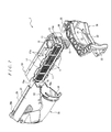
- FIG. 7 is a perspective view of the lever-type connector of FIG. 1 in a disassembled state.
- FIG. 8 is a perspective view illustrative of the bottom and the other side in the left-and-right direction in a state midway through attaching the wire cover to the housing.
- FIG. 9 is a perspective view illustrative of a state where the rear surface side of the wire cover is sandwiched by both side plates of the lever.
- FIG. 10 is a plan view illustrative of a lever-type connector in a state where a lever is positioned at the mating release position.
- FIG. 11 is a cross-sectional view illustrative of a lever-type connector in a state where a lever is set between the mating release position and the mating complete position.
- FIG. 12 is a plan view illustrative of a lever-type connector in a state where a lever is set to the mating complete position.
- FIG. 13 is a cross-sectional view of the
- the lever-type connector 1 shown in FIGS. 1 to 7 includes a housing 10, which accommodates multiple contacts (not illustrated in the drawings), a wire cover 20, which is attached to the rear surface side (upper side in FIG. 3 ) of the housing 10, and a lever 30, which is attached to the housing 10.
- the housing 10 is formed extending in the left-and-right direction (left-and-right direction in FIG. 3 ), and has multiple contact receiving holes 11, which pass through in the front-and-rear direction (up-and-down direction in FIG. 3 ), as shown in FIG. 7 .
- a slider accommodating slot 12 extending in the left-and-right direction on either inner surface in the up-and-down direction (up-and-down direction in FIG. 4 and FIG. 5 ) of the housing 10 is provided.
- a slider 13 is accommodated in each of the sliding accommodating slots 12 so as to move freely in the left-and-right direction. As shown in FIG.
- a pair of pivot receiving portions 16 respectively to which a pivot 34 described later of the lever 30 is joined is provided on an end in the left-and-right direction of the housing 10.
- a latch arm 16a for locking the pivot 34 of the lever joined to each of the pivot receiving portion 16 is provided at the rear of each of the pivot receiving portions 16 of the housing 10.
- Fixed pieces 17 for fixing the wire cover 20 are provided on either end in the left-and-right direction of the rear surface of the housing, as shown in FIG. 7 . Both of the fixed pieces 17 are provided protruding toward the rear, extending in the left-and-right direction.
- Multiple (four in this embodiment) fixing projection portions 17a, which protrude outward, are provided in the left-and-right direction on the outer side surface in the left-and-right direction of each of the fixed pieces 17.
- Each of the sliders 13 is formed in a plate shape, extending in the left-and-right direction.
- Multiple cam grooves (not illustrated in the drawings), which lead in and push out cam pins (not illustrated in the drawings) provided on a mating connector, are provided in the left-and-right direction of the inner surface of each of the sliders 13.
- projection receiving portions 15 respectively to which a slider moving projections 35 described later of the lever 30 are joined are each provided on an end in the left-and-right direction of each of the sliders 13.
- the lever 30 is formed in a U shape and includes a connecting part 33 for connecting a pair of side plates 32 extending in the left-and-right direction and connecting the other ends of both of the side plates 32 to each other.
- the slider moving projection 35 which joins to the projection receiving portions 15 of each of the sliders 13, is formed protruding outward on the outer surface of an end of either of the side plates 32, as shown in FIG. 7 .
- the pivot 34 which joins to each of the pivot receiving portions 16 of the housing 10, is provided protruding inward on the inner surface of the end of both of the side plates 32.
- connecting plates 37 each extending inward are provided on the inner surface of the end of both of the side plates 32, as shown in FIG. 9 .
- Respective ends of both of the side plates 32 are joined to each other by a depression 37a provided at the end of the connecting plate 37 of one of the side plates 32 and a projection 37b provided on end of connecting plate 37 of the other side plate 32.
- a notch 39 extending in the left-and-right direction is provided on the respective inner surfaces of both of the side plates 32.
- a depression 33a onto which a lock piece 27b of a lock member 27 described later of the wire cover 20 is latched is provided on a back side surface of the connecting part 33.
- a protrusion 33b protruding toward the other side in the left-and-right direction relative to a release projection portion 27c described later of the lock member 27 is provided on the connecting part 33.
- the wire cover 20 includes a main body 21, which covers electrical wires (not illustrated in the drawings) connected to the contacts accommodated in the housing 10, and a deterring section 22, which is provided on a side of the main body 21 in the left-to-right direction. Thickness in the up-and-down direction of the main body 21 is less than distance between both of the side plates 32 of the lever 30. Meanwhile, thickness in the up-and-down direction of the deterring section 22 is greater than the distance between both of the side plates 32 of the lever 30. As a result, the deterring section 22 deters the lever 30 that has been rotated until the mating release position (see FIG. 10 ) from rotating further toward the rear.
- the lock member 27 which prevents the lever 30 that has been rotated until the mating completion position (see FIG. 12 and FIG. 13 ) from rotating toward the rear, is provided on the rear surface of the main body 21.
- the lock member 27 is formed in a cantilever plate-spring form and extends from the rear side (one side) toward the front (other side) of the connecting part 33 of the lever 30 set to the mating completion position.
- the lock member 27 has a plate spring 27a, and a lock piece 27b and a release projection portion 27c provided on the outer surface of the plate spring 27a.
- the plate spring 27a is formed extending from the rear side toward the front of the connecting part 33 of the lever 30 set to the mating completion position.
- the lock piece 27b is formed so as to latch onto the depression 33a of the connecting part 33 of the lever 30 set to the mating completion position.
- the release projection portion 27c is provided so as to be positioned on the front side of the connecting part 33 of the lever 30, which is set to the mating completion position. Moreover, the release projection portion 27c is provided so as to protrude toward the other side from the plate spring 27a in the left-and-right direction.
- Each lock projection portion 28 is provided so as to latch onto the side of the notch 39 of each of the side plates 32 of the lever 30 set to the mating completion position.
- a side wall 25a which extends in the direction in which the release projection portion 27c protrudes, is provided on either side of the release projection portion 27c on the rear surface of the main body 21.
- a front wall 25b which extends in the direction in which the release projection portion 27c protrudes, is provided on the front side of the release projection portion 27c on the rear surface of the main body 21.
- the front wall 25b and both of the side walls 25a are formed so as to protrude toward the other side in the left-and-right direction relative to the release projection portion 27c of the lock member 27.
- Fixed parts 29 for fixing the wire cover 20 to the housing 10 are provided on the front end of the top surface and the front end of the bottom surface of the main body 21, as shown in FIG. 7 . Both of the fixed parts 29 are provided extending in the left-and-right direction. Both of the fixed parts 29 are provided so as to protrude outward in the up-and-down direction.
- a fixing groove 29a into which the fixing projection portions 17a of the housing 10 are inserted is provided to the respective inner surfaces of the fixed parts 29 in the left-and-right direction.
- a latch arm 29b is provided on the other end in the left-and-right direction of each of the fixed parts 29. Projections (not illustrated in the drawings) for latching onto the side of the fixing projection portions 17a of the housing 10 are provided on each of the latch arms 29.
- the wire cover 20 is attached to the housing 10 accommodating the multiple contacts.
- the wire cover 20 arranged on the rear side of the housing 10 is slid from one side to the other side in the left-and-right direction of the housing 10, as shown in FIG. 8 .
- the multiple fixing projection portions 17a of both of the fixed pieces 17 of the housing 10 are inserted into the fixing grooves 29a of each of the fixed parts 29 of the wire cover 20.
- the multiple fixing projection portions 17a are inserted into the fixing grooves 29a from one side in the left-and-right direction of the fixing grooves 29a in order from those on the other side in the left-and-right direction.
- the lever 30 is then attached to the housing 10 to which the wire cover 20 is attached.
- the wire cover 20 is first arranged so as for both of the side plates 32 to bridge over the rear surface of the wire cover 20, as shown in FIG. 9 .
- the lever-type connector 1 With the lever-type connector 1 in the assembled state shown in FIG. 1 , if the lever 30 is rotated toward the front (other side), the sliders 13 are moved in the direction of going into the slider accommodating slot 12 of the housing 10. Moreover, if the lever 30 is rotated toward the rear (one side), the sliders 13 are moved in the direction of coming out from the slider accommodating slot 12 of the housing 10.
- the lever 30 is first rotated toward the rear so as to be set to the mating release position, as shown in FIG. 10 .
- the lever 30 that is rotated until the mating release position is unable to be rotated any further toward the rear due to the deterring section 22.
- the lever 30 that has been rotated until the mating release position is prevented from rotating toward the front by the lock projection portions 28 of the main body 21 of the wire cover 20 latching onto the sides of the notches 39 of both of the side plates of the lever 30. Furthermore, with the lever-type connector 1 in which the lever 30 has been set to the mating release position, the sliders 13 are moved in the direction of coming out from the slider accommodating slot 12 of the housing 10 so as to allow insertion of cam pins provided on the mating connector into cam grooves of the sliders 13.
- the lever 30 that has been set to the mating completion position is unable to be rotated any further toward the front because the sides of the notches 39 of both of the side plates 32 keep in contact with the rear surface of the fixing parts 29 of the wire cover 20. Moreover, the lever 30 that has been set to the mating completion position is prevented from rotating toward the rear by the lock piece 27b of the lock member 27 latching onto the depression 33a of the connecting part 33, as shown in FIG. 13 .
- the release projection portion 27c of the lock member 27 is positioned on the front side of the connecting part of the lever 30. According to the lever-type connector 1, this may prevent exertion of external force from the rear side of the wire cover 20 on the release projection portion 27c of the lock member 27. Therefore, according to the lever-type connector 1, prevention of the lock of the lever 30 locked by the lock member 27 from being released unintentionally is possible.
- the release projection portion 27c of the lock member 27 is enclosed by the protrusion 33b of the connecting part 33 of the lever 30 and both of the side walls 25a and the front wall 25b of the wire cover 20.
- the lock of the lever 30 locked by the lock member 27 cannot be released except by inserting a finger in the space enclosed by the protrusion 33b of the connecting part 33 and both of the side walls 25a and the front wall 25b of the wire cover 20. Therefore, according to the lever-type connector 1, prevention of the lock of the lever 30 locked by the lock member 27 from being released unintentionally is possible by external force exerted on the release projection portion 27c of the lock member 27.
- a fingertip is first inserted into the space enclosed by the protrusion 33b of the connecting part 33 of the lever 30 and both of the side walls 25a and the front wall 25b of the wire cover 20.
- the release projection portion 27c of the lock member 27 is then pushed from the other side to the one side in the left-and-right direction by the inserted fingertip.
- the plate spring 27a of the lock member 27 bends inward, thereby releasing the latch of the lock piece 27b of the lock member 27 onto the depression 33a of the connecting part 33 of the lever 30.
- the pad of the finger pushing in the release projection 27c of the lock member 27 makes contact with the front side of the connecting part 33 of the lever 30 and pushes out the connecting part 33 toward the rear. This makes the connecting part 33 of the lever 30 go over the lock piece 27b of the lock member 27 to release the lock of the lever 30 locked by the lock member 27.
- the connecting part 33 of the lever 30 for which the lock by the lock member 27 has been released is pulled on to the pad of the finger, thereby rotating the lever 30 toward the rear.
- the sliders 13 are moved in the direction of coming out from the slider accommodating slot 12 of the housing 10 so that the multiple cam grooves of the sliders 13 push out the cam pins that are provided to the mating connector toward the front.
- the mating of the contacts accommodated in the housing 10 of the lever-type connector 1 and the contacts accommodated in the mating connector is released.
- the release projection portion 27c of the lock member 27 is provided so as to be positioned on the front side of the connecting part of the lever 30.
- the worker may release the latch on the depression 33a of the lock piece 27b by pushing the release projection portion 27c with a finger and pull the front side of the connecting part 33 with the pad of the finger, thereby rotating the lever 30 toward the rear.
- the worker may carry out the release operation for the lock of the lever 30 locked by the lock member 27 and the operation of rotating the lever 30 toward the rear in the same motion. Therefore, according to the lever-type connector 1, simplification of the release operation for the lock of the lever 30 locked by the lock member 27 is possible.
Landscapes
- Details Of Connecting Devices For Male And Female Coupling (AREA)
Claims (3)
- Hebeltyp-Steckverbinder (1), der Folgendes umfasst: ein Gehäuse (10), das einen Kontakt aufnimmt, eine Drahtabdeckung (20), die an der Rückflächenseite des Gehäuses (10) befestigt ist und die einen elektrischen Draht abdeckt, der mit dem in dem Gehäuse (10) aufgenommenen Kontakt verbinden ist, einen Hebel (30), der ein Paar von Seitenplatten (32) und einen Verbindungsteil (33) zum Verbinden der beiden Seitenplatten (32) miteinander umfasst und der die Rückseitenfläche der Drahtabdeckung (20) überbrückt und drehbar an dem Gehäuse (10) befestigt ist, und ein Rastelement (27), das an der Rückfläche der Drahtabdeckung (20) bereitgestellt wird und einer Drehung des Hebels (30) verhindert, wobei: das Zusammenstecken mit einem Gegensteckverbinder freigegeben wird durch das Drehen des Hebels (30) zu der einen Seite hin und das Zusammenstecken mit dem Gegensteckverbinder abgeschlossen wird durch das Drehen des Hebels (30) zu der anderen Seite hin, um so den Hebel (30) zu einer Steckabschlussposition zu stellen, wobei das Rastelement (27) eine Blattfeder (27a) und ein Raststück (27b) und einen Freigabevorsprungsabschnitt (27c), die an der Blattfeder (27a) bereitgestellt werden, umfasst, wobei das Raststück (27b) so geformt ist, dass es an der einen Seite des Verbindungsteils (33) des zu der Steckabschlussposition gestellten Hebels (30) einrastet, dadurch gekennzeichnet, dass
die Blattfeder (27a) so geformt ist, dass sie sich von der einen Seite zu der anderen Seite des Verbindungsteils (33) des zu der Steckabschlussposition gestellten Hebels (30) hin erstreckt, und
der Freigabevorsprungsabschnitt (27c) so bereitgestellt wird, dass er auf der anderen Seite des Verbindungsteils (33) des zu der Steckabschlussposition gestellten Hebels (30) angeordnet ist. - Hebeltyp-Steckverbinder nach Anspruch 1, wobei eine Vertiefung (33a), an der das Raststück (27b) einklinkt, an der Seitenfläche einer Seite des Verbindungsteils (33) bereitgestellt wird.
- Hebeltyp-Steckverbinder nach Anspruch 1 oder Anspruch 2, wobei eine Seitenwand (25a), die sich in der Richtung erstreckt, in der sich der Freigabevorsprung erstreckt, auf beiden Seiten des Freigabevorsprungsabschnitts (27c) an der Rückfläche der Drahtabdeckung (20) bereitgestellt wird.
Applications Claiming Priority (2)
| Application Number | Priority Date | Filing Date | Title |
|---|---|---|---|
| JP2008087617A JP4387438B2 (ja) | 2008-03-28 | 2008-03-28 | レバー式コネクタ |
| PCT/JP2009/055275 WO2009119404A1 (ja) | 2008-03-28 | 2009-03-18 | レバー式コネクタ |
Publications (3)
| Publication Number | Publication Date |
|---|---|
| EP2276123A1 EP2276123A1 (de) | 2011-01-19 |
| EP2276123A4 EP2276123A4 (de) | 2013-09-04 |
| EP2276123B1 true EP2276123B1 (de) | 2014-10-29 |
Family
ID=41113601
Family Applications (1)
| Application Number | Title | Priority Date | Filing Date |
|---|---|---|---|
| EP09724400.8A Active EP2276123B1 (de) | 2008-03-28 | 2009-03-18 | Verbinder des hebeltyps |
Country Status (5)
| Country | Link |
|---|---|
| US (1) | US8221142B2 (de) |
| EP (1) | EP2276123B1 (de) |
| JP (1) | JP4387438B2 (de) |
| CN (1) | CN101981763B (de) |
| WO (1) | WO2009119404A1 (de) |
Families Citing this family (17)
| Publication number | Priority date | Publication date | Assignee | Title |
|---|---|---|---|---|
| JP4468465B2 (ja) * | 2008-03-28 | 2010-05-26 | タイコエレクトロニクスジャパン合同会社 | レバー式コネクタ |
| JP5624874B2 (ja) * | 2010-12-24 | 2014-11-12 | タイコエレクトロニクスジャパン合同会社 | レバー式コネクタ、ワイヤカバー |
| JP5968605B2 (ja) * | 2011-08-29 | 2016-08-10 | タイコエレクトロニクスジャパン合同会社 | レバーを備えたコネクタおよび電線カバー |
| JP5772729B2 (ja) * | 2012-06-06 | 2015-09-02 | 住友電装株式会社 | レバー式コネクタ |
| US9142916B2 (en) * | 2013-03-15 | 2015-09-22 | Tyco Electronics Corporation | Connector assembly with receptacle carriers |
| KR101503507B1 (ko) * | 2014-04-09 | 2015-03-18 | 주식회사 경신 | 차량용 커넥터 |
| EP3007283B8 (de) * | 2014-10-07 | 2019-02-27 | Aptiv Technologies Limited | Mit einem komplementären Gegenstecker steckbarer elektrischer Steckverbinder |
| JP1549393S (de) | 2015-06-26 | 2016-05-16 | ||
| JP1549513S (de) | 2015-06-26 | 2016-05-16 | ||
| JP1549512S (de) * | 2015-06-26 | 2016-05-16 | ||
| JP1549392S (de) * | 2015-06-26 | 2016-05-16 | ||
| JP6268620B1 (ja) | 2016-09-16 | 2018-01-31 | 住友電装株式会社 | レバー式コネクタ |
| JP6222588B1 (ja) | 2016-10-14 | 2017-11-01 | 住友電装株式会社 | レバー式コネクタ |
| EP3322041B1 (de) * | 2016-11-09 | 2019-10-30 | Aptiv Technologies Limited | Steckverbinderanordnung mit integriertem hebelverriegelungssystem |
| JP6210262B1 (ja) | 2017-05-15 | 2017-10-11 | 住友電装株式会社 | レバー式コネクタ |
| JP6931561B2 (ja) * | 2017-07-04 | 2021-09-08 | 日本航空電子工業株式会社 | コネクタ |
| JP7279614B2 (ja) * | 2019-11-01 | 2023-05-23 | 住友電装株式会社 | コネクタ |
Family Cites Families (14)
| Publication number | Priority date | Publication date | Assignee | Title |
|---|---|---|---|---|
| DE69603468T2 (de) * | 1995-04-12 | 2000-01-27 | Whitaker Corp | Modularer elektrischer steckverbinder |
| JP3321039B2 (ja) * | 1997-08-18 | 2002-09-03 | 矢崎総業株式会社 | レバー嵌合式コネクタ |
| JP3252955B2 (ja) | 1998-05-21 | 2002-02-04 | 住友電装株式会社 | レバー式コネクタ |
| US5938458A (en) * | 1998-06-17 | 1999-08-17 | Molex Incorporated | Lever type electrical connector |
| JP3730416B2 (ja) * | 1998-09-10 | 2006-01-05 | 矢崎総業株式会社 | レバー嵌合式コネクタ |
| DE19938930C1 (de) * | 1999-08-17 | 2001-04-12 | Framatome Connectors Int | Elektrischer Steckverbinder |
| US6217354B1 (en) * | 2000-03-20 | 2001-04-17 | Molek Incorporated | Lever type electrical connector |
| JP2003086301A (ja) * | 2001-09-07 | 2003-03-20 | Sumitomo Wiring Syst Ltd | レバー式コネクタ |
| JP3911142B2 (ja) * | 2001-09-19 | 2007-05-09 | 矢崎総業株式会社 | レバー嵌合式コネクタ |
| US7175451B2 (en) * | 2005-03-15 | 2007-02-13 | Tyco Electronics Corporation | Lever mated connector assembly with a position assurance device |
| US7150640B2 (en) * | 2005-04-08 | 2006-12-19 | Yazaki Corporation | Lever type connector |
| JP4602218B2 (ja) * | 2005-10-18 | 2010-12-22 | 矢崎総業株式会社 | レバー式コネクタ |
| WO2007098253A2 (en) * | 2006-02-21 | 2007-08-30 | Tyco Electronics Corporation | Lever mated connector assembly |
| JP4679458B2 (ja) * | 2006-07-19 | 2011-04-27 | モレックス インコーポレイテド | レバー付コネクタ |
-
2008
- 2008-03-28 JP JP2008087617A patent/JP4387438B2/ja active Active
-
2009
- 2009-03-18 EP EP09724400.8A patent/EP2276123B1/de active Active
- 2009-03-18 CN CN200980112485.0A patent/CN101981763B/zh active Active
- 2009-03-18 WO PCT/JP2009/055275 patent/WO2009119404A1/ja active Application Filing
-
2010
- 2010-09-28 US US12/892,308 patent/US8221142B2/en not_active Expired - Fee Related
Also Published As
| Publication number | Publication date |
|---|---|
| EP2276123A1 (de) | 2011-01-19 |
| JP4387438B2 (ja) | 2009-12-16 |
| JP2009245609A (ja) | 2009-10-22 |
| US20110014805A1 (en) | 2011-01-20 |
| EP2276123A4 (de) | 2013-09-04 |
| CN101981763B (zh) | 2013-06-19 |
| WO2009119404A1 (ja) | 2009-10-01 |
| US8221142B2 (en) | 2012-07-17 |
| CN101981763A (zh) | 2011-02-23 |
Similar Documents
| Publication | Publication Date | Title |
|---|---|---|
| EP2276123B1 (de) | Verbinder des hebeltyps | |
| US7785146B2 (en) | Locking device for connector elements and a connector provided with said device | |
| US8246365B2 (en) | Lever-type connector | |
| EP2276121B1 (de) | Verbinder des hebeltyps | |
| JP3086849B2 (ja) | コネクタ嵌合構造 | |
| EP1672747B1 (de) | Verbinder | |
| JP3468451B2 (ja) | コネクタ嵌合構造 | |
| EP2278667A1 (de) | Verbinder des hebeltyps | |
| JP3553805B2 (ja) | コネクタ嵌合構造 | |
| JP3472686B2 (ja) | スライド嵌合型コネクタ | |
| EP2276122B1 (de) | Verbinder des hebeltyps | |
| JP3987736B2 (ja) | レバー式コネクタ | |
| JP3275290B2 (ja) | レバー式コネクタ | |
| JP2002352903A (ja) | レバー式コネクタ | |
| US8419462B2 (en) | Lever type connector | |
| JP4247920B2 (ja) | レバーコネクタ | |
| JP2016537778A (ja) | 双対移動嵌合補助式コネクタ | |
| JP4960853B2 (ja) | レバー式コネクタ | |
| US6623286B2 (en) | Lever-type connector | |
| JP2001160459A (ja) | 半嵌合防止コネクタ | |
| JP3341810B2 (ja) | Lifコネクタ | |
| JP3442661B2 (ja) | レバー嵌合式コネクタ | |
| JP3467388B2 (ja) | スライド嵌合型コネクタ | |
| JP2002298977A (ja) | レバー嵌合式コネクタ | |
| JP6618509B2 (ja) | レバー式コネクタ |
Legal Events
| Date | Code | Title | Description |
|---|---|---|---|
| PUAI | Public reference made under article 153(3) epc to a published international application that has entered the european phase |
Free format text: ORIGINAL CODE: 0009012 |
|
| 17P | Request for examination filed |
Effective date: 20101021 |
|
| AK | Designated contracting states |
Kind code of ref document: A1 Designated state(s): AT BE BG CH CY CZ DE DK EE ES FI FR GB GR HR HU IE IS IT LI LT LU LV MC MK MT NL NO PL PT RO SE SI SK TR |
|
| AX | Request for extension of the european patent |
Extension state: AL BA RS |
|
| DAX | Request for extension of the european patent (deleted) | ||
| A4 | Supplementary search report drawn up and despatched |
Effective date: 20130807 |
|
| RIC1 | Information provided on ipc code assigned before grant |
Ipc: H01R 13/639 20060101AFI20130801BHEP Ipc: H01R 13/629 20060101ALI20130801BHEP |
|
| GRAP | Despatch of communication of intention to grant a patent |
Free format text: ORIGINAL CODE: EPIDOSNIGR1 |
|
| INTG | Intention to grant announced |
Effective date: 20140528 |
|
| GRAS | Grant fee paid |
Free format text: ORIGINAL CODE: EPIDOSNIGR3 |
|
| GRAA | (expected) grant |
Free format text: ORIGINAL CODE: 0009210 |
|
| AK | Designated contracting states |
Kind code of ref document: B1 Designated state(s): AT BE BG CH CY CZ DE DK EE ES FI FR GB GR HR HU IE IS IT LI LT LU LV MC MK MT NL NO PL PT RO SE SI SK TR |
|
| REG | Reference to a national code |
Ref country code: GB Ref legal event code: FG4D |
|
| REG | Reference to a national code |
Ref country code: CH Ref legal event code: EP |
|
| REG | Reference to a national code |
Ref country code: AT Ref legal event code: REF Ref document number: 693960 Country of ref document: AT Kind code of ref document: T Effective date: 20141115 |
|
| REG | Reference to a national code |
Ref country code: IE Ref legal event code: FG4D |
|
| REG | Reference to a national code |
Ref country code: DE Ref legal event code: R096 Ref document number: 602009027441 Country of ref document: DE Effective date: 20141211 |
|
| REG | Reference to a national code |
Ref country code: AT Ref legal event code: MK05 Ref document number: 693960 Country of ref document: AT Kind code of ref document: T Effective date: 20141029 |
|
| REG | Reference to a national code |
Ref country code: NL Ref legal event code: VDEP Effective date: 20141029 |
|
| REG | Reference to a national code |
Ref country code: LT Ref legal event code: MG4D |
|
| PG25 | Lapsed in a contracting state [announced via postgrant information from national office to epo] |
Ref country code: NL Free format text: LAPSE BECAUSE OF FAILURE TO SUBMIT A TRANSLATION OF THE DESCRIPTION OR TO PAY THE FEE WITHIN THE PRESCRIBED TIME-LIMIT Effective date: 20141029 Ref country code: PT Free format text: LAPSE BECAUSE OF FAILURE TO SUBMIT A TRANSLATION OF THE DESCRIPTION OR TO PAY THE FEE WITHIN THE PRESCRIBED TIME-LIMIT Effective date: 20150302 Ref country code: LT Free format text: LAPSE BECAUSE OF FAILURE TO SUBMIT A TRANSLATION OF THE DESCRIPTION OR TO PAY THE FEE WITHIN THE PRESCRIBED TIME-LIMIT Effective date: 20141029 Ref country code: FI Free format text: LAPSE BECAUSE OF FAILURE TO SUBMIT A TRANSLATION OF THE DESCRIPTION OR TO PAY THE FEE WITHIN THE PRESCRIBED TIME-LIMIT Effective date: 20141029 Ref country code: ES Free format text: LAPSE BECAUSE OF FAILURE TO SUBMIT A TRANSLATION OF THE DESCRIPTION OR TO PAY THE FEE WITHIN THE PRESCRIBED TIME-LIMIT Effective date: 20141029 Ref country code: IS Free format text: LAPSE BECAUSE OF FAILURE TO SUBMIT A TRANSLATION OF THE DESCRIPTION OR TO PAY THE FEE WITHIN THE PRESCRIBED TIME-LIMIT Effective date: 20150228 Ref country code: NO Free format text: LAPSE BECAUSE OF FAILURE TO SUBMIT A TRANSLATION OF THE DESCRIPTION OR TO PAY THE FEE WITHIN THE PRESCRIBED TIME-LIMIT Effective date: 20150129 |
|
| PG25 | Lapsed in a contracting state [announced via postgrant information from national office to epo] |
Ref country code: HR Free format text: LAPSE BECAUSE OF FAILURE TO SUBMIT A TRANSLATION OF THE DESCRIPTION OR TO PAY THE FEE WITHIN THE PRESCRIBED TIME-LIMIT Effective date: 20141029 Ref country code: PL Free format text: LAPSE BECAUSE OF FAILURE TO SUBMIT A TRANSLATION OF THE DESCRIPTION OR TO PAY THE FEE WITHIN THE PRESCRIBED TIME-LIMIT Effective date: 20141029 Ref country code: GR Free format text: LAPSE BECAUSE OF FAILURE TO SUBMIT A TRANSLATION OF THE DESCRIPTION OR TO PAY THE FEE WITHIN THE PRESCRIBED TIME-LIMIT Effective date: 20150130 Ref country code: LV Free format text: LAPSE BECAUSE OF FAILURE TO SUBMIT A TRANSLATION OF THE DESCRIPTION OR TO PAY THE FEE WITHIN THE PRESCRIBED TIME-LIMIT Effective date: 20141029 Ref country code: AT Free format text: LAPSE BECAUSE OF FAILURE TO SUBMIT A TRANSLATION OF THE DESCRIPTION OR TO PAY THE FEE WITHIN THE PRESCRIBED TIME-LIMIT Effective date: 20141029 Ref country code: CY Free format text: LAPSE BECAUSE OF FAILURE TO SUBMIT A TRANSLATION OF THE DESCRIPTION OR TO PAY THE FEE WITHIN THE PRESCRIBED TIME-LIMIT Effective date: 20141029 Ref country code: SE Free format text: LAPSE BECAUSE OF FAILURE TO SUBMIT A TRANSLATION OF THE DESCRIPTION OR TO PAY THE FEE WITHIN THE PRESCRIBED TIME-LIMIT Effective date: 20141029 |
|
| REG | Reference to a national code |
Ref country code: DE Ref legal event code: R097 Ref document number: 602009027441 Country of ref document: DE |
|
| PG25 | Lapsed in a contracting state [announced via postgrant information from national office to epo] |
Ref country code: EE Free format text: LAPSE BECAUSE OF FAILURE TO SUBMIT A TRANSLATION OF THE DESCRIPTION OR TO PAY THE FEE WITHIN THE PRESCRIBED TIME-LIMIT Effective date: 20141029 Ref country code: DK Free format text: LAPSE BECAUSE OF FAILURE TO SUBMIT A TRANSLATION OF THE DESCRIPTION OR TO PAY THE FEE WITHIN THE PRESCRIBED TIME-LIMIT Effective date: 20141029 Ref country code: SK Free format text: LAPSE BECAUSE OF FAILURE TO SUBMIT A TRANSLATION OF THE DESCRIPTION OR TO PAY THE FEE WITHIN THE PRESCRIBED TIME-LIMIT Effective date: 20141029 Ref country code: RO Free format text: LAPSE BECAUSE OF FAILURE TO SUBMIT A TRANSLATION OF THE DESCRIPTION OR TO PAY THE FEE WITHIN THE PRESCRIBED TIME-LIMIT Effective date: 20141029 Ref country code: CZ Free format text: LAPSE BECAUSE OF FAILURE TO SUBMIT A TRANSLATION OF THE DESCRIPTION OR TO PAY THE FEE WITHIN THE PRESCRIBED TIME-LIMIT Effective date: 20141029 |
|
| PG25 | Lapsed in a contracting state [announced via postgrant information from national office to epo] |
Ref country code: IT Free format text: LAPSE BECAUSE OF FAILURE TO SUBMIT A TRANSLATION OF THE DESCRIPTION OR TO PAY THE FEE WITHIN THE PRESCRIBED TIME-LIMIT Effective date: 20141029 |
|
| PLBE | No opposition filed within time limit |
Free format text: ORIGINAL CODE: 0009261 |
|
| STAA | Information on the status of an ep patent application or granted ep patent |
Free format text: STATUS: NO OPPOSITION FILED WITHIN TIME LIMIT |
|
| 26N | No opposition filed |
Effective date: 20150730 |
|
| PG25 | Lapsed in a contracting state [announced via postgrant information from national office to epo] |
Ref country code: LU Free format text: LAPSE BECAUSE OF FAILURE TO SUBMIT A TRANSLATION OF THE DESCRIPTION OR TO PAY THE FEE WITHIN THE PRESCRIBED TIME-LIMIT Effective date: 20150318 Ref country code: MC Free format text: LAPSE BECAUSE OF FAILURE TO SUBMIT A TRANSLATION OF THE DESCRIPTION OR TO PAY THE FEE WITHIN THE PRESCRIBED TIME-LIMIT Effective date: 20141029 |
|
| REG | Reference to a national code |
Ref country code: CH Ref legal event code: PL |
|
| GBPC | Gb: european patent ceased through non-payment of renewal fee |
Effective date: 20150318 |
|
| REG | Reference to a national code |
Ref country code: IE Ref legal event code: MM4A |
|
| PG25 | Lapsed in a contracting state [announced via postgrant information from national office to epo] |
Ref country code: LI Free format text: LAPSE BECAUSE OF NON-PAYMENT OF DUE FEES Effective date: 20150331 Ref country code: IE Free format text: LAPSE BECAUSE OF NON-PAYMENT OF DUE FEES Effective date: 20150318 Ref country code: GB Free format text: LAPSE BECAUSE OF NON-PAYMENT OF DUE FEES Effective date: 20150318 Ref country code: CH Free format text: LAPSE BECAUSE OF NON-PAYMENT OF DUE FEES Effective date: 20150331 |
|
| PG25 | Lapsed in a contracting state [announced via postgrant information from national office to epo] |
Ref country code: SI Free format text: LAPSE BECAUSE OF FAILURE TO SUBMIT A TRANSLATION OF THE DESCRIPTION OR TO PAY THE FEE WITHIN THE PRESCRIBED TIME-LIMIT Effective date: 20141029 |
|
| REG | Reference to a national code |
Ref country code: FR Ref legal event code: PLFP Year of fee payment: 8 |
|
| PG25 | Lapsed in a contracting state [announced via postgrant information from national office to epo] |
Ref country code: MT Free format text: LAPSE BECAUSE OF FAILURE TO SUBMIT A TRANSLATION OF THE DESCRIPTION OR TO PAY THE FEE WITHIN THE PRESCRIBED TIME-LIMIT Effective date: 20141029 |
|
| REG | Reference to a national code |
Ref country code: FR Ref legal event code: PLFP Year of fee payment: 9 |
|
| PG25 | Lapsed in a contracting state [announced via postgrant information from national office to epo] |
Ref country code: HU Free format text: LAPSE BECAUSE OF FAILURE TO SUBMIT A TRANSLATION OF THE DESCRIPTION OR TO PAY THE FEE WITHIN THE PRESCRIBED TIME-LIMIT; INVALID AB INITIO Effective date: 20090318 Ref country code: BG Free format text: LAPSE BECAUSE OF FAILURE TO SUBMIT A TRANSLATION OF THE DESCRIPTION OR TO PAY THE FEE WITHIN THE PRESCRIBED TIME-LIMIT Effective date: 20141029 |
|
| PG25 | Lapsed in a contracting state [announced via postgrant information from national office to epo] |
Ref country code: TR Free format text: LAPSE BECAUSE OF FAILURE TO SUBMIT A TRANSLATION OF THE DESCRIPTION OR TO PAY THE FEE WITHIN THE PRESCRIBED TIME-LIMIT Effective date: 20141029 |
|
| PG25 | Lapsed in a contracting state [announced via postgrant information from national office to epo] |
Ref country code: BE Free format text: LAPSE BECAUSE OF FAILURE TO SUBMIT A TRANSLATION OF THE DESCRIPTION OR TO PAY THE FEE WITHIN THE PRESCRIBED TIME-LIMIT Effective date: 20141029 |
|
| REG | Reference to a national code |
Ref country code: FR Ref legal event code: PLFP Year of fee payment: 10 |
|
| PG25 | Lapsed in a contracting state [announced via postgrant information from national office to epo] |
Ref country code: MK Free format text: LAPSE BECAUSE OF FAILURE TO SUBMIT A TRANSLATION OF THE DESCRIPTION OR TO PAY THE FEE WITHIN THE PRESCRIBED TIME-LIMIT Effective date: 20141029 |
|
| PGFP | Annual fee paid to national office [announced via postgrant information from national office to epo] |
Ref country code: FR Payment date: 20190213 Year of fee payment: 11 |
|
| PG25 | Lapsed in a contracting state [announced via postgrant information from national office to epo] |
Ref country code: FR Free format text: LAPSE BECAUSE OF NON-PAYMENT OF DUE FEES Effective date: 20200331 |
|
| PGFP | Annual fee paid to national office [announced via postgrant information from national office to epo] |
Ref country code: DE Payment date: 20230125 Year of fee payment: 15 |