EP2275300A1 - Elektrisches eisenbahnsystem - Google Patents
Elektrisches eisenbahnsystem Download PDFInfo
- Publication number
- EP2275300A1 EP2275300A1 EP08740946A EP08740946A EP2275300A1 EP 2275300 A1 EP2275300 A1 EP 2275300A1 EP 08740946 A EP08740946 A EP 08740946A EP 08740946 A EP08740946 A EP 08740946A EP 2275300 A1 EP2275300 A1 EP 2275300A1
- Authority
- EP
- European Patent Office
- Prior art keywords
- electric
- conductor portion
- power
- contact
- railway system
- Prior art date
- Legal status (The legal status is an assumption and is not a legal conclusion. Google has not performed a legal analysis and makes no representation as to the accuracy of the status listed.)
- Granted
Links
Images


Classifications
-
- B—PERFORMING OPERATIONS; TRANSPORTING
- B60—VEHICLES IN GENERAL
- B60L—PROPULSION OF ELECTRICALLY-PROPELLED VEHICLES; SUPPLYING ELECTRIC POWER FOR AUXILIARY EQUIPMENT OF ELECTRICALLY-PROPELLED VEHICLES; ELECTRODYNAMIC BRAKE SYSTEMS FOR VEHICLES IN GENERAL; MAGNETIC SUSPENSION OR LEVITATION FOR VEHICLES; MONITORING OPERATING VARIABLES OF ELECTRICALLY-PROPELLED VEHICLES; ELECTRIC SAFETY DEVICES FOR ELECTRICALLY-PROPELLED VEHICLES
- B60L5/00—Current collectors for power supply lines of electrically-propelled vehicles
- B60L5/42—Current collectors for power supply lines of electrically-propelled vehicles for collecting current from individual contact pieces connected to the power supply line
-
- B—PERFORMING OPERATIONS; TRANSPORTING
- B60—VEHICLES IN GENERAL
- B60L—PROPULSION OF ELECTRICALLY-PROPELLED VEHICLES; SUPPLYING ELECTRIC POWER FOR AUXILIARY EQUIPMENT OF ELECTRICALLY-PROPELLED VEHICLES; ELECTRODYNAMIC BRAKE SYSTEMS FOR VEHICLES IN GENERAL; MAGNETIC SUSPENSION OR LEVITATION FOR VEHICLES; MONITORING OPERATING VARIABLES OF ELECTRICALLY-PROPELLED VEHICLES; ELECTRIC SAFETY DEVICES FOR ELECTRICALLY-PROPELLED VEHICLES
- B60L5/00—Current collectors for power supply lines of electrically-propelled vehicles
- B60L5/18—Current collectors for power supply lines of electrically-propelled vehicles using bow-type collectors in contact with trolley wire
- B60L5/22—Supporting means for the contact bow
- B60L5/28—Devices for lifting and resetting the collector
-
- B—PERFORMING OPERATIONS; TRANSPORTING
- B60—VEHICLES IN GENERAL
- B60L—PROPULSION OF ELECTRICALLY-PROPELLED VEHICLES; SUPPLYING ELECTRIC POWER FOR AUXILIARY EQUIPMENT OF ELECTRICALLY-PROPELLED VEHICLES; ELECTRODYNAMIC BRAKE SYSTEMS FOR VEHICLES IN GENERAL; MAGNETIC SUSPENSION OR LEVITATION FOR VEHICLES; MONITORING OPERATING VARIABLES OF ELECTRICALLY-PROPELLED VEHICLES; ELECTRIC SAFETY DEVICES FOR ELECTRICALLY-PROPELLED VEHICLES
- B60L50/00—Electric propulsion with power supplied within the vehicle
- B60L50/50—Electric propulsion with power supplied within the vehicle using propulsion power supplied by batteries or fuel cells
- B60L50/53—Electric propulsion with power supplied within the vehicle using propulsion power supplied by batteries or fuel cells in combination with an external power supply, e.g. from overhead contact lines
-
- B—PERFORMING OPERATIONS; TRANSPORTING
- B60—VEHICLES IN GENERAL
- B60L—PROPULSION OF ELECTRICALLY-PROPELLED VEHICLES; SUPPLYING ELECTRIC POWER FOR AUXILIARY EQUIPMENT OF ELECTRICALLY-PROPELLED VEHICLES; ELECTRODYNAMIC BRAKE SYSTEMS FOR VEHICLES IN GENERAL; MAGNETIC SUSPENSION OR LEVITATION FOR VEHICLES; MONITORING OPERATING VARIABLES OF ELECTRICALLY-PROPELLED VEHICLES; ELECTRIC SAFETY DEVICES FOR ELECTRICALLY-PROPELLED VEHICLES
- B60L53/00—Methods of charging batteries, specially adapted for electric vehicles; Charging stations or on-board charging equipment therefor; Exchange of energy storage elements in electric vehicles
- B60L53/10—Methods of charging batteries, specially adapted for electric vehicles; Charging stations or on-board charging equipment therefor; Exchange of energy storage elements in electric vehicles characterised by the energy transfer between the charging station and the vehicle
- B60L53/11—DC charging controlled by the charging station, e.g. mode 4
-
- B—PERFORMING OPERATIONS; TRANSPORTING
- B60—VEHICLES IN GENERAL
- B60L—PROPULSION OF ELECTRICALLY-PROPELLED VEHICLES; SUPPLYING ELECTRIC POWER FOR AUXILIARY EQUIPMENT OF ELECTRICALLY-PROPELLED VEHICLES; ELECTRODYNAMIC BRAKE SYSTEMS FOR VEHICLES IN GENERAL; MAGNETIC SUSPENSION OR LEVITATION FOR VEHICLES; MONITORING OPERATING VARIABLES OF ELECTRICALLY-PROPELLED VEHICLES; ELECTRIC SAFETY DEVICES FOR ELECTRICALLY-PROPELLED VEHICLES
- B60L53/00—Methods of charging batteries, specially adapted for electric vehicles; Charging stations or on-board charging equipment therefor; Exchange of energy storage elements in electric vehicles
- B60L53/30—Constructional details of charging stations
- B60L53/32—Constructional details of charging stations by charging in short intervals along the itinerary, e.g. during short stops
-
- B—PERFORMING OPERATIONS; TRANSPORTING
- B60—VEHICLES IN GENERAL
- B60L—PROPULSION OF ELECTRICALLY-PROPELLED VEHICLES; SUPPLYING ELECTRIC POWER FOR AUXILIARY EQUIPMENT OF ELECTRICALLY-PROPELLED VEHICLES; ELECTRODYNAMIC BRAKE SYSTEMS FOR VEHICLES IN GENERAL; MAGNETIC SUSPENSION OR LEVITATION FOR VEHICLES; MONITORING OPERATING VARIABLES OF ELECTRICALLY-PROPELLED VEHICLES; ELECTRIC SAFETY DEVICES FOR ELECTRICALLY-PROPELLED VEHICLES
- B60L9/00—Electric propulsion with power supply external to the vehicle
-
- B—PERFORMING OPERATIONS; TRANSPORTING
- B60—VEHICLES IN GENERAL
- B60M—POWER SUPPLY LINES, AND DEVICES ALONG RAILS, FOR ELECTRICALLY- PROPELLED VEHICLES
- B60M1/00—Power supply lines for contact with collector on vehicle
- B60M1/36—Single contact pieces along the line for power supply
-
- B—PERFORMING OPERATIONS; TRANSPORTING
- B61—RAILWAYS
- B61C—LOCOMOTIVES; MOTOR RAILCARS
- B61C17/00—Arrangement or disposition of parts; Details or accessories not otherwise provided for; Use of control gear and control systems
- B61C17/06—Power storing devices
-
- B—PERFORMING OPERATIONS; TRANSPORTING
- B60—VEHICLES IN GENERAL
- B60L—PROPULSION OF ELECTRICALLY-PROPELLED VEHICLES; SUPPLYING ELECTRIC POWER FOR AUXILIARY EQUIPMENT OF ELECTRICALLY-PROPELLED VEHICLES; ELECTRODYNAMIC BRAKE SYSTEMS FOR VEHICLES IN GENERAL; MAGNETIC SUSPENSION OR LEVITATION FOR VEHICLES; MONITORING OPERATING VARIABLES OF ELECTRICALLY-PROPELLED VEHICLES; ELECTRIC SAFETY DEVICES FOR ELECTRICALLY-PROPELLED VEHICLES
- B60L2200/00—Type of vehicles
- B60L2200/26—Rail vehicles
-
- B—PERFORMING OPERATIONS; TRANSPORTING
- B60—VEHICLES IN GENERAL
- B60Y—INDEXING SCHEME RELATING TO ASPECTS CROSS-CUTTING VEHICLE TECHNOLOGY
- B60Y2200/00—Type of vehicle
- B60Y2200/30—Railway vehicles
-
- B—PERFORMING OPERATIONS; TRANSPORTING
- B60—VEHICLES IN GENERAL
- B60Y—INDEXING SCHEME RELATING TO ASPECTS CROSS-CUTTING VEHICLE TECHNOLOGY
- B60Y2200/00—Type of vehicle
- B60Y2200/90—Vehicles comprising electric prime movers
- B60Y2200/91—Electric vehicles
-
- Y—GENERAL TAGGING OF NEW TECHNOLOGICAL DEVELOPMENTS; GENERAL TAGGING OF CROSS-SECTIONAL TECHNOLOGIES SPANNING OVER SEVERAL SECTIONS OF THE IPC; TECHNICAL SUBJECTS COVERED BY FORMER USPC CROSS-REFERENCE ART COLLECTIONS [XRACs] AND DIGESTS
- Y02—TECHNOLOGIES OR APPLICATIONS FOR MITIGATION OR ADAPTATION AGAINST CLIMATE CHANGE
- Y02T—CLIMATE CHANGE MITIGATION TECHNOLOGIES RELATED TO TRANSPORTATION
- Y02T10/00—Road transport of goods or passengers
- Y02T10/60—Other road transportation technologies with climate change mitigation effect
- Y02T10/70—Energy storage systems for electromobility, e.g. batteries
-
- Y—GENERAL TAGGING OF NEW TECHNOLOGICAL DEVELOPMENTS; GENERAL TAGGING OF CROSS-SECTIONAL TECHNOLOGIES SPANNING OVER SEVERAL SECTIONS OF THE IPC; TECHNICAL SUBJECTS COVERED BY FORMER USPC CROSS-REFERENCE ART COLLECTIONS [XRACs] AND DIGESTS
- Y02—TECHNOLOGIES OR APPLICATIONS FOR MITIGATION OR ADAPTATION AGAINST CLIMATE CHANGE
- Y02T—CLIMATE CHANGE MITIGATION TECHNOLOGIES RELATED TO TRANSPORTATION
- Y02T10/00—Road transport of goods or passengers
- Y02T10/60—Other road transportation technologies with climate change mitigation effect
- Y02T10/7072—Electromobility specific charging systems or methods for batteries, ultracapacitors, supercapacitors or double-layer capacitors
-
- Y—GENERAL TAGGING OF NEW TECHNOLOGICAL DEVELOPMENTS; GENERAL TAGGING OF CROSS-SECTIONAL TECHNOLOGIES SPANNING OVER SEVERAL SECTIONS OF THE IPC; TECHNICAL SUBJECTS COVERED BY FORMER USPC CROSS-REFERENCE ART COLLECTIONS [XRACs] AND DIGESTS
- Y02—TECHNOLOGIES OR APPLICATIONS FOR MITIGATION OR ADAPTATION AGAINST CLIMATE CHANGE
- Y02T—CLIMATE CHANGE MITIGATION TECHNOLOGIES RELATED TO TRANSPORTATION
- Y02T30/00—Transportation of goods or passengers via railways, e.g. energy recovery or reducing air resistance
-
- Y—GENERAL TAGGING OF NEW TECHNOLOGICAL DEVELOPMENTS; GENERAL TAGGING OF CROSS-SECTIONAL TECHNOLOGIES SPANNING OVER SEVERAL SECTIONS OF THE IPC; TECHNICAL SUBJECTS COVERED BY FORMER USPC CROSS-REFERENCE ART COLLECTIONS [XRACs] AND DIGESTS
- Y02—TECHNOLOGIES OR APPLICATIONS FOR MITIGATION OR ADAPTATION AGAINST CLIMATE CHANGE
- Y02T—CLIMATE CHANGE MITIGATION TECHNOLOGIES RELATED TO TRANSPORTATION
- Y02T90/00—Enabling technologies or technologies with a potential or indirect contribution to GHG emissions mitigation
- Y02T90/10—Technologies relating to charging of electric vehicles
- Y02T90/12—Electric charging stations
-
- Y—GENERAL TAGGING OF NEW TECHNOLOGICAL DEVELOPMENTS; GENERAL TAGGING OF CROSS-SECTIONAL TECHNOLOGIES SPANNING OVER SEVERAL SECTIONS OF THE IPC; TECHNICAL SUBJECTS COVERED BY FORMER USPC CROSS-REFERENCE ART COLLECTIONS [XRACs] AND DIGESTS
- Y02—TECHNOLOGIES OR APPLICATIONS FOR MITIGATION OR ADAPTATION AGAINST CLIMATE CHANGE
- Y02T—CLIMATE CHANGE MITIGATION TECHNOLOGIES RELATED TO TRANSPORTATION
- Y02T90/00—Enabling technologies or technologies with a potential or indirect contribution to GHG emissions mitigation
- Y02T90/10—Technologies relating to charging of electric vehicles
- Y02T90/14—Plug-in electric vehicles
Definitions
- the present invention relates to an electric railway system configured to include an electric car and an electric-power supply device that supplies electric power to the electric car.
- an electric car is configured to run by taking in electric power from an overhead catenary with a power collector, and by driving an electric motor using the electric power from the overhead catenary.
- an overhead catenary is removed from a part of a section of an existing electrified route, or only a route-extended portion of an existing electrified route is set as overhead catenary free.
- the electric car uses electric power from the overhead catenary, and when the electric car runs in an overhead-catenary free section, the electric car runs using electric power from electric-power storage elements.
- overhead catenaries are removed from all routes, and an electric car runs using only electric power from electric-power storage elements.
- a power source for an electric charge and an overhead catenary are provided at only terminal stations and intermediate stop stations. Electric power taken in from this overhead catenary is charged to the electric-power storage elements (for example, Patent Document 1).
- Patent Document 1 Japanese Patent Application Laid-open No. 2006-238652
- an electric car raises a pantograph as a power collector, and runs as an existing electric railway by collecting electric power from an overhead catenary as an overhead conductor portion.
- the electric car lowers the pantograph, and runs using electric power of electric-power storage elements.
- the electric car raises the pantograph and quickly charges electric power to the electric power storage elements from the overhead catenary provided to charge electric power, during a few dozens of seconds to a few minutes while the electric car is stopped at a station and the like.
- a case that an abnormality is present in a contact state between a pantograph and an overhead catenary is considered here.
- a contact resistance between the pantograph and the overhead catenary increases, the temperature at a contact portion between the pantograph and the overhead catenary increases, and this has a risk of fusing this portion.
- the present invention has been achieved in view of the above problems, and an object of the present invention is to provide an electric railway system suitable for each mode of running in a section having no overhead catenary, an electric charge to electric-power storage elements while an electric car is stopped, and running in a section having an overhead catenary, and particularly, capable of stably and safely performing a rapid electric charge to the electric-power storage elements while the electric car is stopped.
- an electric railway system is configured to comprise an electric car and an electric-power supply device that supplies electric power to the electric car.
- the electric-power supply device comprises a power source, and an overhead conductor portion connected to the power source.
- the electric car comprises a power collector that is installed on a roof of the electric car, has a contact conductor portion contactable to the overhead conductor portion, and is capable of performing a raising operation and a lowering operation of the contact conductor portion based on an instruction from outside, a switching unit that is connected to the power collector and performs opening and closing of a main circuit as a supply route of electric power, an electric-power conversion device that is connected to the switching unit and performs an electric power conversion, an electric-power storage device that is connected to the electric-power conversion device and stores electric power, an electric motor that is driven by the electric-power conversion device and drives the electric car, and a control unit that controls at least the switching unit.
- the electric railway system according to the present invention can provide an electric railway system suitable for each mode of running of an electric car in a section having no overhead catenary, an electric charge to electric-power storage elements while an electric car is stopped, and running of the electric car in a section having an overhead catenary, and particularly, capable of stably and safely performing a rapid electric charge to electric-power storage elements while the electric car is stopped.
- FIG. 1 is a configuration example of an electric railway system according to an embodiment of the present invention.
- FIG. 1 is a configuration example of an electric railway system according to an embodiment of the present invention.
- an apparatus installed on the ground includes a rail 4 on which an electric car 10 runs, an overhead catenary 1A as an overhead conductor portion for a rapid electric charge provided at a station 50, an overhead catenary 1B provided in a normal electrified section, and an electric power substation 70 as a power source to the electric car 10, connected to the overhead catenary 1A and the overhead catenary 1B.
- the electric power substation 70 is shown by a simple mark of a direct-current voltage source in FIG. 1 , the electric power substation 70 is generally configured to decrease a special high-voltage alternate current received from an electric-power system, and supply a voltage of a direct current about 600 volts to 1500 volts rectified by a rectifier to the overhead catenary 1A or the overhead catenary 1B.
- the overhead catenary 1A and the overhead catenary 1B can be configured to receive electric power from separate electric power substations (not shown), respectively.
- the overhead catenary 1B is used for the electric car 10 to collect electric power while running. Therefore, the overhead catenary 1B is generally configured to be supported above the rail 4 with supporting pillars having a trolley catenary, configured by materials based on copper, provided at constant intervals, to improve the following capability of the pantograph.
- the overhead catenary 1A is used for the electric car 10 to collect electric power in a stopped state, and a large amount of current flows with a accompanying rapid electric charge. Therefore, for the overhead catenary 1A, it is preferable to use a rigid overhead catenary based on a copper sheet having a large cross-sectional area and high rigidity.
- the electric car 10 is installed with a pantograph 2A as a power collector for a rapid electric charge, and a pantograph 2B as a power collector for an existing electrified section. Details of the electric car 10 are described later.
- a section A is a normal electrified section, and the electric car 10 runs in this section while receiving electric power from the overhead catenary 1B by raising the pantograph 2B.
- a section B is an overhead catenary free section, and the electric car 10 runs in this section by using electric power from the electric-power storage elements installed in the electric car 10 by lowering and storing the pantographs 2A and 2B.
- a section C is a rapid-electric-charge overhead-catenary section, and the electric car 10 charges electric power corresponding to electric power consumed while running in the section B, into the electric-power storage elements installed in the electric car 10. In this case, the section C is assumed as a station and an exclusive electric-charge section, where the electric car 10 keeps stopping and charges electric power by raising the pantograph 2A.
- FIG. 2 is a configuration example of the electric car 10 according to the embodiment of the present invention.
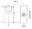
- FIG. 3 is a configuration example of an electric-power conversion device 12 according to the embodiment of the present invention.
- the electric car 10 is installed with the pantograph 2A for a rapid electric charge, and the pantograph 2B for collecting electric power in an existing electrified section.
- the pantographs 2A and 2B are configured to be able to be selectively raised or lowered. Although both pantographs are electrically connected to each other in FIG. 2 , the pantographs can be configured such that their connection is switched over according to a necessity instead of being always connected.
- the pantograph 2A is provided with a temperature detector 6 that measures a temperature of a contact conductor portion 60 (see FIG. 4 described later) contacted to the overhead catenary 1A, and a state detector 5 that detects a raise/lower state of the pantograph 2A.
- a temperature detection signal TH from the temperature detector 6, and a state detection signal PS from the state detector 5 are input to a control unit 15, respectively.
- a switching unit 11 configured by a switch or a breaker that opens or closes a main circuit as an electric-power supply path is connected to the pantograph 2A.
- the electric-power conversion device 12 is arranged at a latter stage of the switching unit 11.
- the electric-power conversion device 12 has an input filter circuit including a reactor 40 and a capacitor 41, and a voltage detector 42 that detects a voltage of the reactor 40 and outputs the detected voltage to the control unit 15 as a reactor voltage DV.
- a DC/DC converter circuit and an inverter circuit are connected to a latter stage of the input filter circuit.
- the DC/DC converter circuit and the inverter circuit are configured by a known technique, and detailed explanations thereof will be omitted.
- the present invention is not limited by configurations of the DC/DC converter circuit and the inverter circuit.
- an output of the electric-power conversion device 12 is connected to an electric-power storage device 13 and an electric motor 16.
- the electric-power storage device 13 is configured to incorporate electric-power storage elements such as secondary batteries of lithium-ion batteries and nickel-hydrogen batteries, and electric double-layer capacitors.
- the electric-power storage device 13 is configured to perform an electric charge via the electric-power conversion device 12 by electric power received via the pantograph 2A or the pantograph 2B, supply stored electric power to the electric motor 16 via the electric-power conversion device 12, and drive wheels 3.
- the present invention is not limited by a kind of electric-power storage element.
- a voltage detector 17 is provided at a latter stage of the pantograph 2A, and is configured to input a pantograph voltage ES detected, to the control unit 15.
- the control unit 15 is input with a pantograph raise/lower instruction PC from outside, and is input with the temperature detection signal TH, the state detection signal PS, and the pantograph voltage ES, from the pantograph 2A.
- a detected value of a reactor voltage DV is input to the control unit 15 by the electric-power conversion device 12.
- the control unit 15 outputs an on/off signal KC to the switching unit 11, outputs a control signal GC to the electric-power conversion device 12, and outputs a compulsory-lower signal PD to the pantograph 2A.
- the control signal GC includes current instructions to adjust a current in the DC/DC converter circuit and the inverter circuit, and respective on/off signals. A detailed configuration and an operation example of the control unit 15 are explained later.
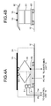
- FIGS. 4A and 4B are configuration examples of the pantograph 2A and the overhead catenary 1A according to the embodiment of the present invention.
- the pantograph 2A as a power collector includes a linkage mechanism 62, a frame 61 configured by a conductor, a contact conductor portion 60 electrically connected to the frame 61, the state detector 5, and the temperature detector 6.
- the pantograph 2B has a configuration similar to that of the pantograph 2B except a difference described below.
- pantograph raise/lower instruction PC input from outside is a raise instruction
- the linkage mechanism 62 raises the frame 61 by using a spring, an air pressure, a motorized force or the like, contacts the contact conductor portion 60 provided at a top portion of the frame 61 to the overhead catenary 1A, and obtains electric power.
- the linkage mechanism 62 lowers the frame 61 by using a spring, an air pressure, a motorized force or the like, and breaks a contact between the contact conductor portion 60 provided at the top portion of the frame 61 and the overhead catenary 1A.
- the compulsory-lower signal PD is input from the control unit 15.
- the linkage mechanism 62 quickly lowers the frame 61 by using a spring, an air pressure, a motorized force or the like, and breaks a contact between the contact conductor portion 60 provided at the top portion of the frame 61 and the overhead catenary 1A.
- the state detector 5 detects a raise/lower state of the contact conductor portion 60. For example, when the state detector 5 determines that the contact conductor portion 60 has reached the overhead catenary 1A and contacted thereto, the state detector 5 sets the state detection signal PS ON. On the other hand, when the state detector 5 determines that a contact between the contact conductor portion 60 and the overhead catenary 1A has been broken, the state detector 5 sets the state detection signal PS OFF.
- a contact state can be determined by detecting a positional relationship between the contact conductor portion 60 and the overhead catenary 1A or by detecting a contact pressure. There is no limit to a method of this detection.
- the state detection signal PS can be a signal indicating a detected position itself of the contact conductor portion 60.
- the control unit 15 determines whether the contact conductor portion 60 has reached the overhead catenary 1A or a contact has been broken.
- the temperature detector 6 measures the temperature of the contact conductor portion 60, and sets the temperature detection signal TH ON when the temperature exceeds a predetermined set value, for example.
- the temperature detector 6 sets the temperature detection signal TH OFF when the temperature of the contact conductor portion 60 becomes equal to or lower than a predetermined value.
- the temperature detection signal TH can be a signal indicating a detected temperature itself of the contact conductor portion 60.
- the control unit 15 determines whether a detected temperature is equal to or higher or lower than a predetermined value.
- a difference between the pantograph 2A and the pantograph 2B is explained.
- a carbon material having a smaller friction coefficient to the overhead catenary than that of copper is used.
- a copper alloy or the like having a high electric conductivity and a high melting point.
- linkage mechanisms 62 There is also a difference between linkage mechanisms 62.
- the linkage mechanism 62 set in the pantograph 2A has a larger lifting force of the contact conductor portion 60 than that a linkage mechanism set in the pantograph 2B has.
- the linkage mechanism 62 set in the pantograph 2A secures a higher contact pressure between the contact conductor portion 60 and the overhead catenary 1A than that the linkage mechanism set in the pantograph 2B has.
- pantograph 2B is used while the electric car is running as described above, the following points are preferably taken into consideration. Because the pantograph 2B collects electric power by sliding the contact conductor portion 60 with the overhead catenary 1B during running of the electric car 10, it is important to avoid abrasion of the overhead catenary 1B. Therefore, it becomes a preferable condition to use a carbon material having a small friction coefficient, at a portion of the contact conductor portion 60 contacting the overhead catenary 1B.
- pantograph 2A is used while the electric car is stopped as described above, the following point is preferably taken into consideration. Because the pantograph 2A collects electric power from the overhead catenary 1A while the electric car 10 is stopped, the overhead catenary 1A is not abraded.
- the linkage mechanism 62 set in the pantograph 2A has a larger lifting force of the contact conductor portion 60 than that the linkage mechanism of the pantograph 2B has.
- a contact pressure between the contact conductor portion 60 and the overhead catenary 1A is set larger than that of the pantograph 2B, an electric contact between the contact conductor portion 60 and the overhead catenary 1A can be set more secure.
- the overhead catenary 1A is explained next. As shown in FIG. 4B , two overhead catenaries 1A are provided in parallel in a proceeding direction of the electric car 10, and each of the overhead catenaries 1A is configured to be contacted to the contact conductor portion 60.
- the number of the overhead catenaries is not limited to two as shown in FIGS. 4A and 4B , and can be plural, which is larger than two.
- Plural overhead catenaries 1A are electrically connected to each other, and receive a voltage supply from the electric power substation 70.
- a contact with the overhead catenary 1A can be set more secure, and electric power can be collected stably.
- the overhead catenary 1A can be configured to be able to be raised slightly above by a lifting force of the pantograph 2A. Only when the pantograph 2A is raised above by a constant amount, a position detector (not shown) can detect this, and the electric power substation 70 can apply a voltage to the overhead catenary 1A. By arranging this configuration, there is an effect that electric power can be supplied to the pantograph 2A only when a contact force is securely present between the contact conductor portion 60 and the overhead catenary 1A, and power can be collected more stably.
- FIG. 5 is a configuration example of the control unit 15 according to the embodiment of the present invention.
- the control unit 15 is configured to include: a pantograph-voltage-abnormality determining unit 20 that inputs the pantograph voltage ES, determines an abnormality of the pantograph voltage ES, and outputs a result of the determination as a determination signal ESD; a reactor-voltage-abnormality determining unit 21 that inputs the reactor voltage DV, determines an abnormality of the reactor voltage DV, and outputs a result of the determination as a determination signal DVD; a temperature determining unit 22 that inputs the temperature detection signal TH of the contact conductor portion 60, determines an abnormality of temperature, and outputs a result of the determination as a determination signal THD; a raise/lower determining unit 23 that inputs the state detection signal PS, determines a raise/lower state of the pantograph 2A, and outputs a result of the determination as a determination signal PSD; a welding determination unit 24 that inputs the pantograph raise/lower instruction PC and the state detection signal PS,
- the pantograph-voltage-abnormality determining unit 20 determines an abnormality of a contact state between the overhead catenary 1A and the contact conductor portion 60 based on the pantograph voltage ES as a physical quantity indicating a level of a contact state between the overhead catenary 1A and the contact conductor portion 60.
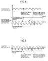
- FIG. 6 is a waveform example of the pantograph voltage ES and a differential value thereof according to the embodiment of the present invention.
- the pantograph-voltage-abnormality determining unit 20 obtains a differential value (a change rate) of the pantograph voltage ES, and monitors whether the differential value is within a determination value.
- the pantograph-voltage-abnormality determining unit 20 determines that an electric contact between the overhead catenary 1A and the contact conductor portion 60 is defective (abnormal), and sets the determination signal ESD ON (H level).
- the pantograph-voltage-abnormality determining unit 20 can be configured to pass the pantograph voltage ES through a high-pass filter, extract a voltage variation component (a frequency component) generated due to a contact defect state, and perform an abnormality determination based on this extraction.
- the reactor-voltage-abnormality determining unit 21 performs an abnormality determination of a contact state between the overhead catenary 1A and the contact conductor portion 60 based on the reactor voltage DV as a physical quantity indicating a level of a contact state between the overhead catenary 1A and the contact conductor portion 60.
- FIG. 7 is a waveform example of the reactor voltage DV according to the embodiment of the present invention.
- the reactor-voltage-abnormality determining unit 21 monitors whether the reactor voltage DV is within a determination value. When the reactor voltage DV takes a value other than the determination value, the reactor-voltage-abnormality determining unit 21 determines that an electric contact between the overhead catenary 1A and the contact conductor portion 60 is defective (abnormal), and sets the determination signal DVD ON (H level).
- the reactor-voltage-abnormality determining unit 21 can perform an abnormality determination based on a differential value (a change rate) of the reactor voltage DVD in a similar manner to that of a process by the pantograph-voltage-abnormality determining unit 20.
- the reactor-voltage-abnormality determining unit 21 can be also configured to pass the reactor voltage DV through a high-pass filter, extract a voltage variation component (a frequency component) generated due to a contact defect state, and perform an abnormality determination based on this extraction. It can be configured such that at least one of the pantograph-voltage-abnormality determining unit 20 and the reactor-voltage-abnormality determining unit 21 is provided.
- FIG. 7 it can be configured such that a Fourier transform unit or the like analyzes a frequency included in the pantograph voltage ES or in the reactor voltage DV, and compares a result of the analysis with a characteristic of a frequency distribution generated in a state that an arc occurs. Based on a result of this comparison, the pantograph-voltage-abnormality determining unit 20 or the reactor-voltage-abnormality determining unit 21 can determine that an electric contact between the overhead catenary 1A and the contact conductor portion 60 is defective (abnormal), and set the determination signal ESD or the determination signal DVD ON (H level).
- a Fourier transform unit or the like analyzes a frequency included in the pantograph voltage ES or in the reactor voltage DV, and compares a result of the analysis with a characteristic of a frequency distribution generated in a state that an arc occurs. Based on a result of this comparison, the pantograph-voltage-abnormality determining unit 20 or the reactor-voltage-abnormality determining
- the temperature determining unit 22 sets the determination signal THD ON (H level), when the temperature detection signal TH as a physical quantity indicating a level of a contact state shows an excess temperature of the contact conductor portion 60.
- the raise/lower determining unit 23 sets the determination signal PSD ON (H level), when the state detection signal PS as a physical quantity indicating a level of a contact state shows that a raise position of the contact conductor portion 60 is at or lower than a predetermined value and is not contacted to the overhead catenary 1A.
- the OR circuit 27 takes a logical sum of the determination signals ESD, DVD, THD, and PSD. With this configuration, when any one of events that can occur when a contact state between the overhead catenary 1A and the contact conductor portion 60 is abnormal occurs, the OR circuit 27 determines that a contact state between the overhead catenary 1A and the contact conductor portion 60 is abnormal, and outputs a determination signal ER0.
- the AND circuit 28 takes a logical product of the stop signal ST indicating that the electric car 10 is stopped, and outputs a determination signal ER1.
- the determination signal ER1 When the determination signal ER1 is ON (H level), an electric contact state between the overhead catenary 1A and the contact conductor portion 60 is determined to be abnormal. Therefore, the determination signal ER is output via the OR circuit 29 and the NAND circuit 31.
- the on/off signal KC and the control signal GC are compulsively turned off, without depending on the basic on/off signal KCO and the basic control signal GCO generated separately. Consequently, the electric-power conversion device 12 is stopped, and a main circuit current is interrupted by turning off the switching unit 11. This configuration prevents a current from flowing to the pantograph 2A, and expansion of an abnormal range can be avoided.
- the welding determination unit 24 determines that the contact conductor portion 60 is welded to the overhead catenary 1A and the pantograph 2A cannot be lowered, and sets the determination signal MDD ON (H level).
- the determination signal MDD When the determination signal MDD is set ON (H level), it is determined that the overhead catenary 1A and the contact conductor portion 60 are adhered together by an arc generated between the overhead catenary 1A and the contact conductor portion 60.
- the determination signal ER is output via the OR circuit 29 and the NAND circuit 31.
- the on/off signal KC and the control signal GC are compulsively set OFF, without depending on the basic on/off signal KCO and the basic control signal GCO generated separately. Consequently, a starting of the electric-power conversion device 12 (particularly, an inverter circuit) is prohibited, a current conduction to the electric motor 16 is prohibited, and the switching unit 11 is turned off to interrupt a main circuit current.
- the compulsory-lower control unit 26 sets the compulsory-lower basic signal PDS ON (H level), when the electric car 10 moves due to a loosened brake of the electric car 10 or by an intentional operation during a rapid electric charge to the electric car 10 by raising the pantograph 2A. Accordingly, the determination signal ER is output via the OR circuit 29 and the NAND circuit 31.
- the on/off signal KC and the control signal GC are compulsively set OFF, without depending on the basic on/off signal KCO and the basic control signal GCO generated separately. Consequently, the electric-power conversion device 12 is turned off, and the switching unit 11 is turned off to interrupt the main circuit current.
- the compulsory-lower signal PD is output, and the pantograph 2A is lowered.
- the delay time of the delay circuit 30 is set to a time required for the switching unit 11 and the electric-power conversion device 12 to become in an off state or is set to a longer time.
- the delay circuit 30 secures a time from an on-timing of the compulsory-lower basic signal PDS until when the compulsory-lower signal PD is set ON, and a lowering of the pantograph 2A is started after the main circuit current is set to zero by stopping the electric-power conversion device 12 and the switching unit 11. Therefore, a current is not interrupted due to a disconnection of the contact conductor portion 60 of the pantograph 2A from the overhead catenary 1A, and a melting loss due to the occurrence of an arc between the pantograph 2A and the overhead catenary 1A can be avoided.
- a similar effect can be also obtained by configuring an interlock circuit such that the compulsory-lower signal PD is set ON, after turning OFF of the switching unit 11 and the electric-power conversion device 12 is confirmed by receiving a feedback signal (not shown) indicating an on/off state from the switching unit 11 and the electric-power conversion device 12.
- a temperature of the contact conductor portion 60 is indirectly detected by a thermo-viewer (not shown) or the like, and the determination signal THD is set ON (H level) based on this detection.
- a thermo-viewer not shown
- an optical sensor not shown
- the temperature of the contact conductor portion 60 is determined to be a high temperature, and the determination signal THD is set ON (H level).
- the pantograph 2A used during the rapid electric charge while the electric car is stopped and the pantograph 2B used to collect electric power from the overhead catenary during running of the electric car are installed in the electric car 10.
- a separate pantograph having both characteristics of the pantograph 2A and the pantograph 2B can be shared.
- the configuration described in the present embodiment can be applied also in this case.
- the pantograph 2B can be used instead of the pantograph 2A.
- the configuration described in the present embodiment can be applied also in this case.
- an electric railway system suitable for each mode of running of an electric car in a section having no overhead catenary, an electric charge to electric-power storage elements while an electric car is stopped, and running of the electric car in a section having an overhead catenary, and particularly, capable of stably performing a rapid electric charge to the electric-power storage elements while the electric car is stopped.
- the electric railway system according to the present invention is useful as an invention in which a rapid electric charge to electric-power storage elements can be stably and safely performed while an electric car is stopped.
Applications Claiming Priority (1)
| Application Number | Priority Date | Filing Date | Title |
|---|---|---|---|
| PCT/JP2008/058278 WO2009133608A1 (ja) | 2008-04-30 | 2008-04-30 | 電気鉄道システム |
Publications (3)
| Publication Number | Publication Date |
|---|---|
| EP2275300A1 true EP2275300A1 (de) | 2011-01-19 |
| EP2275300A4 EP2275300A4 (de) | 2011-10-26 |
| EP2275300B1 EP2275300B1 (de) | 2013-11-13 |
Family
ID=41254839
Family Applications (1)
| Application Number | Title | Priority Date | Filing Date |
|---|---|---|---|
| EP08740946.2A Not-in-force EP2275300B1 (de) | 2008-04-30 | 2008-04-30 | Elektrisches eisenbahnsystem |
Country Status (7)
| Country | Link |
|---|---|
| US (1) | US8596434B2 (de) |
| EP (1) | EP2275300B1 (de) |
| JP (1) | JP4346678B1 (de) |
| KR (1) | KR101162454B1 (de) |
| CN (1) | CN102015356B (de) |
| CA (1) | CA2725409C (de) |
| WO (1) | WO2009133608A1 (de) |
Cited By (8)
| Publication number | Priority date | Publication date | Assignee | Title |
|---|---|---|---|---|
| EP2535219A1 (de) * | 2011-06-14 | 2012-12-19 | ALSTOM Transport SA | Energieaufladevorrichtung für ein Fahrzeug |
| EP2572922A1 (de) * | 2011-09-26 | 2013-03-27 | Alcatel Lucent | Verfahren zum Laden einer Energiespeichereinheit |
| EP2860058A4 (de) * | 2012-06-07 | 2016-03-02 | Mitsubishi Electric Corp | Elektrische fahrzeugsteuerungsvorrichtung |
| EP3160791B1 (de) * | 2014-08-28 | 2019-08-07 | Siemens Mobility GmbH | Elektrische schaltung für ein fahrzeug und verfahren zur kontaktaufnahme und/oder -beendigung eines fahrzeugs mit einem fahrzeugexternen elektrischen netz |
| EP3085570B1 (de) * | 2015-04-20 | 2019-12-04 | ALSTOM Transport Technologies | Stromversorgungsnetz für ein elektrisch angetriebenes fahrzeug und verfahren zur steuerung solch eines stromversorgungssystems |
| FR3105116A1 (fr) * | 2019-12-23 | 2021-06-25 | Alstom Transport Technologies | Dispositif de captage d’énergie électrique pour véhicule, notamment ferroviaire, et véhicule, notamment ferroviaire, comprenant un tel dispositif |
| AT525171B1 (de) * | 2021-07-12 | 2023-01-15 | Plasser & Theurer Export Von Bahnbaumaschinen Gmbh | Verfahren zum Betreiben einer Gleisbaumaschine |
| WO2023061774A1 (de) * | 2021-10-14 | 2023-04-20 | Volkswagen Ag | Verfahren zum betrieb eines elektrisch angetriebenen kraftfahrzeugs |
Families Citing this family (38)
| Publication number | Priority date | Publication date | Assignee | Title |
|---|---|---|---|---|
| JP5372545B2 (ja) * | 2009-02-06 | 2013-12-18 | 川崎重工業株式会社 | パンタグラフ自動昇降装置 |
| CN102958747B (zh) | 2010-07-30 | 2015-06-17 | 三菱重工业株式会社 | 架线交通系统及其控制方法 |
| JP2012120404A (ja) * | 2010-12-03 | 2012-06-21 | Mitsubishi Heavy Ind Ltd | 電動車両への給電システム |
| EP2671748B2 (de) * | 2011-01-31 | 2023-11-15 | Hitachi, Ltd. | Antriebssystem, antriebssystem für ein schienenfahrzeug sowie schienenfahrzeug und mehrwaggonzug damit |
| JP5791363B2 (ja) * | 2011-05-10 | 2015-10-07 | 株式会社小松製作所 | 自走式ケーブル中継台車 |
| WO2012176295A1 (ja) * | 2011-06-23 | 2012-12-27 | 三菱電機株式会社 | 列車情報管理装置および列車情報管理方法 |
| KR101251552B1 (ko) * | 2011-10-13 | 2013-04-08 | 한국철도기술연구원 | 도전성 유체를 이용한 비접촉 급전 장치 |
| US8893830B2 (en) * | 2011-11-18 | 2014-11-25 | Caterpillar Inc. | Automated pantograph control for mining truck power system |
| CN102700425A (zh) * | 2012-04-26 | 2012-10-03 | 江苏中辆科技有限公司 | 新能源有轨公交运营系统 |
| CN102910079B (zh) * | 2012-09-20 | 2014-11-19 | 南车南京浦镇车辆有限公司 | 基于列车网络系统的地铁列车受电弓控制方法 |
| CN102975724B (zh) * | 2012-12-07 | 2015-05-20 | 南车株洲电力机车有限公司 | 一种城轨车辆的蓄电池与受流器牵引供电系统 |
| JP5943484B2 (ja) * | 2013-05-07 | 2016-07-05 | シオン電機株式会社 | 直流電源使用時に生ずるアーク放電防止システム |
| KR101478083B1 (ko) * | 2013-06-13 | 2014-12-31 | 현대로템 주식회사 | 판토그라프 오토드롭 시스템 및 방법 |
| WO2015169326A1 (en) | 2014-05-05 | 2015-11-12 | Volvo Truck Corporation | A method and arrangement for controlling charging of an electrical storage system in a vehicle |
| JP6317179B2 (ja) * | 2014-05-21 | 2018-04-25 | 近畿車輌株式会社 | 鉄道車両用の集電システム |
| CN104210385B (zh) * | 2014-08-19 | 2016-09-07 | 吉林大学 | 全程无负序间歇无供电网的电气化铁路电网系统 |
| KR101551140B1 (ko) | 2015-01-12 | 2015-09-07 | 주식회사 다원시스 | 철도차량의 운전실 독립형 냉난방 시스템 |
| JP6484855B2 (ja) * | 2015-04-21 | 2019-03-20 | 株式会社明電舎 | トロリ線の摩耗推定方法及び推定装置 |
| DE102015006308B4 (de) * | 2015-05-16 | 2022-01-27 | Audi Ag | Ladevorrichtung zum induktiven Laden eines elektrischen Energiespeichers eines Kraftfahrzeugs und Verfahren zum Betreiben einer Ladevorrichtung |
| DE102015215174A1 (de) * | 2015-08-07 | 2017-02-09 | Siemens Aktiengesellschaft | Vorrichtung und ein Verfahren zum oberleitungslosen Betreiben eines Schienenfahrzeugs |
| EP3165398B1 (de) * | 2015-11-09 | 2023-07-26 | ALSTOM Transport Technologies | Verfahren und system zur überwachung eines pantografen eines schienenfahrzeugs und schienenfahrzeug |
| KR101989963B1 (ko) | 2017-04-10 | 2019-06-17 | 주식회사 우진기전 | 철도차량의 개폐장치용 스마트 유닛 |
| DE102017215135A1 (de) * | 2017-08-30 | 2019-02-28 | Siemens Mobility GmbH | Verfahren sowie Vorrichtung zur Überprüfung einer Kontaktierung eines Stromabnehmers |
| CN107650690B (zh) * | 2017-09-20 | 2020-12-04 | 株洲时代电子技术有限公司 | 一种铁路工程机械混合动力源控制方法 |
| JP7042597B2 (ja) * | 2017-12-04 | 2022-03-28 | 株式会社東芝 | 車両用制御装置及び電動車両 |
| PL3853623T3 (pl) * | 2018-10-16 | 2022-11-14 | Siemens Mobility GmbH | Sposób monitorowania akumulatora w pojeździe szynowym |
| JP6749681B1 (ja) * | 2019-05-27 | 2020-09-02 | 株式会社ExH | 電力供給システム |
| CN110293850A (zh) * | 2019-06-13 | 2019-10-01 | 宝鸡中车时代工程机械有限公司 | 具有接触网供电电源系统的轨道工程车 |
| CN110133418B (zh) * | 2019-06-18 | 2021-09-14 | 重庆市轨道交通(集团)有限公司 | 受电弓检测装置 |
| JP7301686B2 (ja) * | 2019-09-12 | 2023-07-03 | 東海旅客鉄道株式会社 | 電力変換システム |
| KR20210099674A (ko) * | 2020-02-04 | 2021-08-13 | 현대자동차주식회사 | 전기버스 충전 시스템 및 이를 이용한 충전방법 |
| KR102490484B1 (ko) * | 2021-02-05 | 2023-01-25 | 한국자동차연구원 | 판토그라프의 이상 진단 장치 및 방법 |
| KR102515775B1 (ko) * | 2021-02-08 | 2023-03-30 | 한국자동차연구원 | 전기차의 충전을 위한 판토그라프의 결빙 방지 시스템 및 그 작동 방법 |
| US11923632B2 (en) | 2021-11-24 | 2024-03-05 | Caterpillar Inc. | Terminal assembly for conductor rod having multiple degrees of freedom |
| US11688973B2 (en) | 2021-11-24 | 2023-06-27 | Caterpillar Inc. | Connector assembly for conductor rod having multiple degrees of freedom |
| US20230162889A1 (en) * | 2021-11-24 | 2023-05-25 | Caterpillar Inc. | Radial and axial interface between conductor rod and work machine |
| US11859370B2 (en) | 2021-11-24 | 2024-01-02 | Caterpillar Inc. | Multi-tiered interface between conductor rod and work machine |
| CN114384072B (zh) * | 2021-11-30 | 2023-07-11 | 杭州申昊科技股份有限公司 | 一种用于轨道巡检刚性接触网的磨耗检测方法及系统 |
Citations (6)
| Publication number | Priority date | Publication date | Assignee | Title |
|---|---|---|---|---|
| JPH1146402A (ja) * | 1997-07-25 | 1999-02-16 | East Japan Railway Co | 直流電気車両のパンダグラフ・アーク検出装置 |
| US20020139629A1 (en) * | 2001-03-29 | 2002-10-03 | Alstom | Method of and a system for controlling the supply of electrical power to an electrically propelled vehicle designed to operate in an external power supply mode or in an autonomous power supply mode |
| JP2003319509A (ja) * | 2002-04-22 | 2003-11-07 | Odakyu Dentetsu Kk | 鉄道車両のパンタグラフ保護方法及び装置 |
| JP2005287184A (ja) * | 2004-03-30 | 2005-10-13 | Railway Technical Res Inst | 監視装置 |
| US20070188127A1 (en) * | 2002-02-07 | 2007-08-16 | Elin Ebg Traction Gmbh | Vehicle Comprising a Battery Drive and a Method for Operating a Vehicle of this Type |
| JP2007295640A (ja) * | 2006-04-20 | 2007-11-08 | Railway Technical Res Inst | 架線・バッテリハイブリッド車両のパンタグラフ誤動作防止装置及び方法 |
Family Cites Families (11)
| Publication number | Priority date | Publication date | Assignee | Title |
|---|---|---|---|---|
| JPS571003U (de) * | 1980-06-02 | 1982-01-06 | ||
| JPH0797881B2 (ja) * | 1986-07-29 | 1995-10-18 | 東洋電機製造株式会社 | トロリ−アシスト車両用パンタグラフの架線外れ検知装置 |
| RU2108936C1 (ru) | 1997-04-03 | 1998-04-20 | Валерий Григорьевич Запускалов | Мобильный контрольно-вычислительный комплекс для диагностики контактной сети железнодорожного транспорта |
| RU2110419C1 (ru) | 1997-04-24 | 1998-05-10 | Владимир Анатольевич Гасюта | Транспортное средство с автономным ходом |
| RU2137622C1 (ru) | 1997-06-17 | 1999-09-20 | Галиулин Равиль Масгутович | Устройство для измерения параметров контактного провода |
| JP3911621B2 (ja) | 2000-06-06 | 2007-05-09 | 株式会社日立製作所 | バッテリ駆動列車の鉄道システム |
| FR2819759B1 (fr) * | 2001-01-24 | 2003-05-23 | Alstom | Systeme d'alimentation d'un vehicule a traction electrique |
| KR100588049B1 (ko) | 2003-12-30 | 2006-06-09 | 한국철도기술연구원 | 철도차량에서 집전장치의 측정시스템과의 인터페이스를위한 차량신호 측정장치 |
| JP2006238652A (ja) | 2005-02-25 | 2006-09-07 | Toshiba Corp | 鉄道エネルギー補給システム |
| KR100719193B1 (ko) | 2005-06-30 | 2007-05-16 | 미쓰비시덴키 가부시키가이샤 | 차량용 보조 전원 장치 |
| JP4167678B2 (ja) | 2005-08-26 | 2008-10-15 | 株式会社神戸製鋼所 | 電動車走行システム |
-
2008
- 2008-04-30 EP EP08740946.2A patent/EP2275300B1/de not_active Not-in-force
- 2008-04-30 KR KR1020107024217A patent/KR101162454B1/ko active IP Right Grant
- 2008-04-30 CA CA2725409A patent/CA2725409C/en not_active Expired - Fee Related
- 2008-04-30 WO PCT/JP2008/058278 patent/WO2009133608A1/ja active Application Filing
- 2008-04-30 JP JP2008547795A patent/JP4346678B1/ja active Active
- 2008-04-30 CN CN2008801289810A patent/CN102015356B/zh not_active Expired - Fee Related
- 2008-04-30 US US12/936,837 patent/US8596434B2/en active Active
Patent Citations (6)
| Publication number | Priority date | Publication date | Assignee | Title |
|---|---|---|---|---|
| JPH1146402A (ja) * | 1997-07-25 | 1999-02-16 | East Japan Railway Co | 直流電気車両のパンダグラフ・アーク検出装置 |
| US20020139629A1 (en) * | 2001-03-29 | 2002-10-03 | Alstom | Method of and a system for controlling the supply of electrical power to an electrically propelled vehicle designed to operate in an external power supply mode or in an autonomous power supply mode |
| US20070188127A1 (en) * | 2002-02-07 | 2007-08-16 | Elin Ebg Traction Gmbh | Vehicle Comprising a Battery Drive and a Method for Operating a Vehicle of this Type |
| JP2003319509A (ja) * | 2002-04-22 | 2003-11-07 | Odakyu Dentetsu Kk | 鉄道車両のパンタグラフ保護方法及び装置 |
| JP2005287184A (ja) * | 2004-03-30 | 2005-10-13 | Railway Technical Res Inst | 監視装置 |
| JP2007295640A (ja) * | 2006-04-20 | 2007-11-08 | Railway Technical Res Inst | 架線・バッテリハイブリッド車両のパンタグラフ誤動作防止装置及び方法 |
Non-Patent Citations (1)
| Title |
|---|
| See also references of WO2009133608A1 * |
Cited By (15)
| Publication number | Priority date | Publication date | Assignee | Title |
|---|---|---|---|---|
| EP2535219A1 (de) * | 2011-06-14 | 2012-12-19 | ALSTOM Transport SA | Energieaufladevorrichtung für ein Fahrzeug |
| FR2976529A1 (fr) * | 2011-06-14 | 2012-12-21 | Alstom Transport Sa | Dispositif de recharge en energie pour un vehicule |
| US9030163B2 (en) | 2011-06-14 | 2015-05-12 | Alstom Transport Sa | Energy recharging device for a vehicle |
| EP2572922A1 (de) * | 2011-09-26 | 2013-03-27 | Alcatel Lucent | Verfahren zum Laden einer Energiespeichereinheit |
| EP2860058A4 (de) * | 2012-06-07 | 2016-03-02 | Mitsubishi Electric Corp | Elektrische fahrzeugsteuerungsvorrichtung |
| US9434259B2 (en) | 2012-06-07 | 2016-09-06 | Mitsubishi Electric Corporation | Electric vehicle control apparatus |
| EP3160791B1 (de) * | 2014-08-28 | 2019-08-07 | Siemens Mobility GmbH | Elektrische schaltung für ein fahrzeug und verfahren zur kontaktaufnahme und/oder -beendigung eines fahrzeugs mit einem fahrzeugexternen elektrischen netz |
| EP3085570B1 (de) * | 2015-04-20 | 2019-12-04 | ALSTOM Transport Technologies | Stromversorgungsnetz für ein elektrisch angetriebenes fahrzeug und verfahren zur steuerung solch eines stromversorgungssystems |
| AU2016202445B2 (en) * | 2015-04-20 | 2020-10-22 | Alstom Transport Technologies | An electrical power supply system for an electrically propelled vehicle and methods of controlling such an electrical power supply system |
| FR3105116A1 (fr) * | 2019-12-23 | 2021-06-25 | Alstom Transport Technologies | Dispositif de captage d’énergie électrique pour véhicule, notamment ferroviaire, et véhicule, notamment ferroviaire, comprenant un tel dispositif |
| EP3842275A1 (de) * | 2019-12-23 | 2021-06-30 | ALSTOM Transport Technologies | Elektrische energieaufnahmevorrichtung für ein fahrzeug, insbesondere ein schienenfahrzeug, und fahrzeug, insbesondere schienenfahrzeug, das eine solchen vorrichtung umfasst |
| AT525171B1 (de) * | 2021-07-12 | 2023-01-15 | Plasser & Theurer Export Von Bahnbaumaschinen Gmbh | Verfahren zum Betreiben einer Gleisbaumaschine |
| AT525171A4 (de) * | 2021-07-12 | 2023-01-15 | Plasser & Theurer Export Von Bahnbaumaschinen Gmbh | Verfahren zum Betreiben einer Gleisbaumaschine |
| WO2023285155A1 (de) * | 2021-07-12 | 2023-01-19 | Plasser & Theurer, Export von Bahnbaumaschinen, Gesellschaft m.b.H. | Verfahren zum betreiben einer gleisbaumaschine |
| WO2023061774A1 (de) * | 2021-10-14 | 2023-04-20 | Volkswagen Ag | Verfahren zum betrieb eines elektrisch angetriebenen kraftfahrzeugs |
Also Published As
| Publication number | Publication date |
|---|---|
| WO2009133608A1 (ja) | 2009-11-05 |
| KR20110004402A (ko) | 2011-01-13 |
| EP2275300B1 (de) | 2013-11-13 |
| US8596434B2 (en) | 2013-12-03 |
| CN102015356A (zh) | 2011-04-13 |
| JP4346678B1 (ja) | 2009-10-21 |
| CA2725409A1 (en) | 2009-11-05 |
| CN102015356B (zh) | 2013-11-13 |
| CA2725409C (en) | 2014-11-25 |
| JPWO2009133608A1 (ja) | 2011-08-25 |
| KR101162454B1 (ko) | 2012-07-04 |
| EP2275300A4 (de) | 2011-10-26 |
| US20110030574A1 (en) | 2011-02-10 |
Similar Documents
| Publication | Publication Date | Title |
|---|---|---|
| US8596434B2 (en) | Electric railway system | |
| EP2014505B1 (de) | Durchhangloses transportsystem und ladeverfahren dafür | |
| AU2011251493B2 (en) | AC electric vehicle | |
| KR101560995B1 (ko) | 철도 차량 시스템 | |
| EP2504190B1 (de) | Ladestation und vorrichtung zur aufnahme der ladung für ein elektrofahrzeug | |
| KR101461692B1 (ko) | 전기 구동 철도 차량의 지붕에 배치된 전기 설비 | |
| EP3471991B1 (de) | Vorrichtung zum laden eines elektrofahrzeugs und verfahren zur verifizierung des kontakts zwischen einer vorrichtung zum laden eines elektrofahrzeugs und das elektrofahrzeug | |
| JP2011526858A (ja) | 電気車両用充電ステーション | |
| EP2524836A2 (de) | Elektrisches Stromversorgungsverfahren eines Schienenfahrzeugs, entsprechendes Stromversorgungssystem im Bahnhof, entsprechendes Energiespeichersystem an Bord des Schienenfahrzeugs und entsprechendes Schienenfahrzeug | |
| EP2860058B1 (de) | Elektrische fahrzeugsteuerungsvorrichtung | |
| EP2839982B1 (de) | Pantograf für Schienenfahrzeug, der Enteisungsmittel umfasst, und Enteisungsverfahren eines Pantografen | |
| CN108473057A (zh) | 用于监视电力系统中的电绝缘电阻的方法和系统 | |
| JP2009113691A (ja) | 鉄道における電池駆動式車両の地上給電システム | |
| JP2010130772A (ja) | 鉄道車両駆動システム | |
| CN104691367A (zh) | 一种储能式轨道交通车辆的充电控制系统 | |
| RU2456174C1 (ru) | Электрическая железнодорожная система | |
| KR102004313B1 (ko) | 제3궤조 집전슈의 결빙 방지 장치 | |
| KR20100130711A (ko) | 궤도차량용 유도급전시스템 | |
| JP3455076B2 (ja) | 交直両用電気車 | |
| RU2392134C1 (ru) | Пантографный токоприемник |
Legal Events
| Date | Code | Title | Description |
|---|---|---|---|
| PUAI | Public reference made under article 153(3) epc to a published international application that has entered the european phase |
Free format text: ORIGINAL CODE: 0009012 |
|
| 17P | Request for examination filed |
Effective date: 20101025 |
|
| AK | Designated contracting states |
Kind code of ref document: A1 Designated state(s): AT BE BG CH CY CZ DE DK EE ES FI FR GB GR HR HU IE IS IT LI LT LU LV MC MT NL NO PL PT RO SE SI SK TR |
|
| AX | Request for extension of the european patent |
Extension state: AL BA MK RS |
|
| DAX | Request for extension of the european patent (deleted) | ||
| A4 | Supplementary search report drawn up and despatched |
Effective date: 20110922 |
|
| RIC1 | Information provided on ipc code assigned before grant |
Ipc: B60L 3/00 20060101ALI20110916BHEP Ipc: B60L 5/28 20060101ALI20110916BHEP Ipc: B61C 3/02 20060101ALI20110916BHEP Ipc: B60L 13/00 20060101AFI20110916BHEP Ipc: B60L 11/18 20060101ALI20110916BHEP |
|
| 17Q | First examination report despatched |
Effective date: 20120524 |
|
| REG | Reference to a national code |
Ref country code: DE Ref legal event code: R079 Ref document number: 602008028717 Country of ref document: DE Free format text: PREVIOUS MAIN CLASS: B60L0013000000 Ipc: B60L0005280000 |
|
| GRAP | Despatch of communication of intention to grant a patent |
Free format text: ORIGINAL CODE: EPIDOSNIGR1 |
|
| RIC1 | Information provided on ipc code assigned before grant |
Ipc: B60L 9/00 20060101ALI20130422BHEP Ipc: B60L 5/42 20060101ALI20130422BHEP Ipc: B60M 1/36 20060101ALI20130422BHEP Ipc: B60L 5/28 20060101AFI20130422BHEP Ipc: B60L 11/18 20060101ALI20130422BHEP Ipc: B61C 17/06 20060101ALI20130422BHEP |
|
| INTG | Intention to grant announced |
Effective date: 20130527 |
|
| GRAS | Grant fee paid |
Free format text: ORIGINAL CODE: EPIDOSNIGR3 |
|
| GRAA | (expected) grant |
Free format text: ORIGINAL CODE: 0009210 |
|
| AK | Designated contracting states |
Kind code of ref document: B1 Designated state(s): AT BE BG CH CY CZ DE DK EE ES FI FR GB GR HR HU IE IS IT LI LT LU LV MC MT NL NO PL PT RO SE SI SK TR |
|
| REG | Reference to a national code |
Ref country code: GB Ref legal event code: FG4D |
|
| REG | Reference to a national code |
Ref country code: CH Ref legal event code: EP |
|
| REG | Reference to a national code |
Ref country code: AT Ref legal event code: REF Ref document number: 640421 Country of ref document: AT Kind code of ref document: T Effective date: 20131215 |
|
| REG | Reference to a national code |
Ref country code: IE Ref legal event code: FG4D |
|
| REG | Reference to a national code |
Ref country code: DE Ref legal event code: R096 Ref document number: 602008028717 Country of ref document: DE Effective date: 20140109 |
|
| REG | Reference to a national code |
Ref country code: NL Ref legal event code: VDEP Effective date: 20131113 |
|
| REG | Reference to a national code |
Ref country code: AT Ref legal event code: MK05 Ref document number: 640421 Country of ref document: AT Kind code of ref document: T Effective date: 20131113 |
|
| REG | Reference to a national code |
Ref country code: LT Ref legal event code: MG4D |
|
| PG25 | Lapsed in a contracting state [announced via postgrant information from national office to epo] |
Ref country code: HR Free format text: LAPSE BECAUSE OF FAILURE TO SUBMIT A TRANSLATION OF THE DESCRIPTION OR TO PAY THE FEE WITHIN THE PRESCRIBED TIME-LIMIT Effective date: 20131113 Ref country code: NL Free format text: LAPSE BECAUSE OF FAILURE TO SUBMIT A TRANSLATION OF THE DESCRIPTION OR TO PAY THE FEE WITHIN THE PRESCRIBED TIME-LIMIT Effective date: 20131113 Ref country code: LT Free format text: LAPSE BECAUSE OF FAILURE TO SUBMIT A TRANSLATION OF THE DESCRIPTION OR TO PAY THE FEE WITHIN THE PRESCRIBED TIME-LIMIT Effective date: 20131113 Ref country code: SE Free format text: LAPSE BECAUSE OF FAILURE TO SUBMIT A TRANSLATION OF THE DESCRIPTION OR TO PAY THE FEE WITHIN THE PRESCRIBED TIME-LIMIT Effective date: 20131113 Ref country code: FI Free format text: LAPSE BECAUSE OF FAILURE TO SUBMIT A TRANSLATION OF THE DESCRIPTION OR TO PAY THE FEE WITHIN THE PRESCRIBED TIME-LIMIT Effective date: 20131113 Ref country code: IS Free format text: LAPSE BECAUSE OF FAILURE TO SUBMIT A TRANSLATION OF THE DESCRIPTION OR TO PAY THE FEE WITHIN THE PRESCRIBED TIME-LIMIT Effective date: 20140313 Ref country code: NO Free format text: LAPSE BECAUSE OF FAILURE TO SUBMIT A TRANSLATION OF THE DESCRIPTION OR TO PAY THE FEE WITHIN THE PRESCRIBED TIME-LIMIT Effective date: 20140213 |
|
| PG25 | Lapsed in a contracting state [announced via postgrant information from national office to epo] |
Ref country code: AT Free format text: LAPSE BECAUSE OF FAILURE TO SUBMIT A TRANSLATION OF THE DESCRIPTION OR TO PAY THE FEE WITHIN THE PRESCRIBED TIME-LIMIT Effective date: 20131113 Ref country code: LV Free format text: LAPSE BECAUSE OF FAILURE TO SUBMIT A TRANSLATION OF THE DESCRIPTION OR TO PAY THE FEE WITHIN THE PRESCRIBED TIME-LIMIT Effective date: 20131113 Ref country code: ES Free format text: LAPSE BECAUSE OF FAILURE TO SUBMIT A TRANSLATION OF THE DESCRIPTION OR TO PAY THE FEE WITHIN THE PRESCRIBED TIME-LIMIT Effective date: 20131113 Ref country code: CY Free format text: LAPSE BECAUSE OF FAILURE TO SUBMIT A TRANSLATION OF THE DESCRIPTION OR TO PAY THE FEE WITHIN THE PRESCRIBED TIME-LIMIT Effective date: 20131113 Ref country code: BE Free format text: LAPSE BECAUSE OF FAILURE TO SUBMIT A TRANSLATION OF THE DESCRIPTION OR TO PAY THE FEE WITHIN THE PRESCRIBED TIME-LIMIT Effective date: 20131113 |
|
| PG25 | Lapsed in a contracting state [announced via postgrant information from national office to epo] |
Ref country code: PT Free format text: LAPSE BECAUSE OF FAILURE TO SUBMIT A TRANSLATION OF THE DESCRIPTION OR TO PAY THE FEE WITHIN THE PRESCRIBED TIME-LIMIT Effective date: 20140313 |
|
| PG25 | Lapsed in a contracting state [announced via postgrant information from national office to epo] |
Ref country code: EE Free format text: LAPSE BECAUSE OF FAILURE TO SUBMIT A TRANSLATION OF THE DESCRIPTION OR TO PAY THE FEE WITHIN THE PRESCRIBED TIME-LIMIT Effective date: 20131113 |
|
| REG | Reference to a national code |
Ref country code: DE Ref legal event code: R097 Ref document number: 602008028717 Country of ref document: DE |
|
| PG25 | Lapsed in a contracting state [announced via postgrant information from national office to epo] |
Ref country code: SK Free format text: LAPSE BECAUSE OF FAILURE TO SUBMIT A TRANSLATION OF THE DESCRIPTION OR TO PAY THE FEE WITHIN THE PRESCRIBED TIME-LIMIT Effective date: 20131113 Ref country code: PL Free format text: LAPSE BECAUSE OF FAILURE TO SUBMIT A TRANSLATION OF THE DESCRIPTION OR TO PAY THE FEE WITHIN THE PRESCRIBED TIME-LIMIT Effective date: 20131113 Ref country code: CZ Free format text: LAPSE BECAUSE OF FAILURE TO SUBMIT A TRANSLATION OF THE DESCRIPTION OR TO PAY THE FEE WITHIN THE PRESCRIBED TIME-LIMIT Effective date: 20131113 Ref country code: RO Free format text: LAPSE BECAUSE OF FAILURE TO SUBMIT A TRANSLATION OF THE DESCRIPTION OR TO PAY THE FEE WITHIN THE PRESCRIBED TIME-LIMIT Effective date: 20131113 |
|
| PLBE | No opposition filed within time limit |
Free format text: ORIGINAL CODE: 0009261 |
|
| STAA | Information on the status of an ep patent application or granted ep patent |
Free format text: STATUS: NO OPPOSITION FILED WITHIN TIME LIMIT |
|
| PG25 | Lapsed in a contracting state [announced via postgrant information from national office to epo] |
Ref country code: DK Free format text: LAPSE BECAUSE OF FAILURE TO SUBMIT A TRANSLATION OF THE DESCRIPTION OR TO PAY THE FEE WITHIN THE PRESCRIBED TIME-LIMIT Effective date: 20131113 |
|
| 26N | No opposition filed |
Effective date: 20140814 |
|
| REG | Reference to a national code |
Ref country code: DE Ref legal event code: R097 Ref document number: 602008028717 Country of ref document: DE Effective date: 20140814 |
|
| PG25 | Lapsed in a contracting state [announced via postgrant information from national office to epo] |
Ref country code: LU Free format text: LAPSE BECAUSE OF FAILURE TO SUBMIT A TRANSLATION OF THE DESCRIPTION OR TO PAY THE FEE WITHIN THE PRESCRIBED TIME-LIMIT Effective date: 20140430 Ref country code: MC Free format text: LAPSE BECAUSE OF FAILURE TO SUBMIT A TRANSLATION OF THE DESCRIPTION OR TO PAY THE FEE WITHIN THE PRESCRIBED TIME-LIMIT Effective date: 20131113 |
|
| REG | Reference to a national code |
Ref country code: CH Ref legal event code: PL |
|
| REG | Reference to a national code |
Ref country code: IE Ref legal event code: MM4A |
|
| PG25 | Lapsed in a contracting state [announced via postgrant information from national office to epo] |
Ref country code: CH Free format text: LAPSE BECAUSE OF NON-PAYMENT OF DUE FEES Effective date: 20140430 Ref country code: LI Free format text: LAPSE BECAUSE OF NON-PAYMENT OF DUE FEES Effective date: 20140430 |
|
| PG25 | Lapsed in a contracting state [announced via postgrant information from national office to epo] |
Ref country code: SI Free format text: LAPSE BECAUSE OF FAILURE TO SUBMIT A TRANSLATION OF THE DESCRIPTION OR TO PAY THE FEE WITHIN THE PRESCRIBED TIME-LIMIT Effective date: 20131113 |
|
| PG25 | Lapsed in a contracting state [announced via postgrant information from national office to epo] |
Ref country code: IT Free format text: LAPSE BECAUSE OF FAILURE TO SUBMIT A TRANSLATION OF THE DESCRIPTION OR TO PAY THE FEE WITHIN THE PRESCRIBED TIME-LIMIT Effective date: 20131113 |
|
| PG25 | Lapsed in a contracting state [announced via postgrant information from national office to epo] |
Ref country code: IE Free format text: LAPSE BECAUSE OF NON-PAYMENT OF DUE FEES Effective date: 20140430 |
|
| REG | Reference to a national code |
Ref country code: FR Ref legal event code: PLFP Year of fee payment: 9 |
|
| PG25 | Lapsed in a contracting state [announced via postgrant information from national office to epo] |
Ref country code: MT Free format text: LAPSE BECAUSE OF FAILURE TO SUBMIT A TRANSLATION OF THE DESCRIPTION OR TO PAY THE FEE WITHIN THE PRESCRIBED TIME-LIMIT Effective date: 20131113 |
|
| REG | Reference to a national code |
Ref country code: DE Ref legal event code: R084 Ref document number: 602008028717 Country of ref document: DE |
|
| PG25 | Lapsed in a contracting state [announced via postgrant information from national office to epo] |
Ref country code: BG Free format text: LAPSE BECAUSE OF FAILURE TO SUBMIT A TRANSLATION OF THE DESCRIPTION OR TO PAY THE FEE WITHIN THE PRESCRIBED TIME-LIMIT Effective date: 20131113 |
|
| REG | Reference to a national code |
Ref country code: GB Ref legal event code: 746 Effective date: 20160519 |
|
| PG25 | Lapsed in a contracting state [announced via postgrant information from national office to epo] |
Ref country code: GR Free format text: LAPSE BECAUSE OF FAILURE TO SUBMIT A TRANSLATION OF THE DESCRIPTION OR TO PAY THE FEE WITHIN THE PRESCRIBED TIME-LIMIT Effective date: 20140214 |
|
| PG25 | Lapsed in a contracting state [announced via postgrant information from national office to epo] |
Ref country code: HU Free format text: LAPSE BECAUSE OF FAILURE TO SUBMIT A TRANSLATION OF THE DESCRIPTION OR TO PAY THE FEE WITHIN THE PRESCRIBED TIME-LIMIT; INVALID AB INITIO Effective date: 20080430 Ref country code: TR Free format text: LAPSE BECAUSE OF FAILURE TO SUBMIT A TRANSLATION OF THE DESCRIPTION OR TO PAY THE FEE WITHIN THE PRESCRIBED TIME-LIMIT Effective date: 20131113 |
|
| REG | Reference to a national code |
Ref country code: FR Ref legal event code: PLFP Year of fee payment: 10 |
|
| REG | Reference to a national code |
Ref country code: FR Ref legal event code: PLFP Year of fee payment: 11 |
|
| PGFP | Annual fee paid to national office [announced via postgrant information from national office to epo] |
Ref country code: GB Payment date: 20180329 Year of fee payment: 11 |
|
| PGFP | Annual fee paid to national office [announced via postgrant information from national office to epo] |
Ref country code: FR Payment date: 20180315 Year of fee payment: 11 |
|
| PGFP | Annual fee paid to national office [announced via postgrant information from national office to epo] |
Ref country code: DE Payment date: 20190416 Year of fee payment: 12 |
|
| GBPC | Gb: european patent ceased through non-payment of renewal fee |
Effective date: 20190430 |
|
| PG25 | Lapsed in a contracting state [announced via postgrant information from national office to epo] |
Ref country code: GB Free format text: LAPSE BECAUSE OF NON-PAYMENT OF DUE FEES Effective date: 20190430 |
|
| PG25 | Lapsed in a contracting state [announced via postgrant information from national office to epo] |
Ref country code: FR Free format text: LAPSE BECAUSE OF NON-PAYMENT OF DUE FEES Effective date: 20190430 |
|
| REG | Reference to a national code |
Ref country code: DE Ref legal event code: R119 Ref document number: 602008028717 Country of ref document: DE |
|
| PG25 | Lapsed in a contracting state [announced via postgrant information from national office to epo] |
Ref country code: DE Free format text: LAPSE BECAUSE OF NON-PAYMENT OF DUE FEES Effective date: 20201103 |