EP2272735B1 - Electric power steering system - Google Patents
Electric power steering system Download PDFInfo
- Publication number
- EP2272735B1 EP2272735B1 EP10168731.7A EP10168731A EP2272735B1 EP 2272735 B1 EP2272735 B1 EP 2272735B1 EP 10168731 A EP10168731 A EP 10168731A EP 2272735 B1 EP2272735 B1 EP 2272735B1
- Authority
- EP
- European Patent Office
- Prior art keywords
- steering
- feedback
- assist
- speed
- motor
- Prior art date
- Legal status (The legal status is an assumption and is not a legal conclusion. Google has not performed a legal analysis and makes no representation as to the accuracy of the status listed.)
- Not-in-force
Links
Images


Classifications
-
- B—PERFORMING OPERATIONS; TRANSPORTING
- B62—LAND VEHICLES FOR TRAVELLING OTHERWISE THAN ON RAILS
- B62D—MOTOR VEHICLES; TRAILERS
- B62D5/00—Power-assisted or power-driven steering
- B62D5/04—Power-assisted or power-driven steering electrical, e.g. using an electric servo-motor connected to, or forming part of, the steering gear
- B62D5/0457—Power-assisted or power-driven steering electrical, e.g. using an electric servo-motor connected to, or forming part of, the steering gear characterised by control features of the drive means as such
- B62D5/046—Controlling the motor
- B62D5/0463—Controlling the motor calculating assisting torque from the motor based on driver input
Definitions
- the invention relates to an electric power steering system.
- Power steering systems for a vehicle include an electric power steering system (EPS) that uses a motor as a drive source.
- EPS electric power steering system
- a control unit thereof detects a steering torque that is transmitted via a steering shaft, and calculates a target assist force that should be applied to a steering system based on the steering torque. Then, the control unit executes a feedback control so that an actual current value is brought to a current command value that corresponds to the target assist force.
- the control unit controls an operation of an actuator by adjusting a drive current that is applied to a motor.
- an increase in quietness is one of the most important issues to be addressed.
- Examples of the situations where an increase in quietness is especially demanded include a situation where a steering operation is performed when a vehicle is traveling at a low speed, and a situation where a steering operation is performed when the vehicle is not traveling, that is, a steering wheel is turned by a large amount when the vehicle is not traveling.
- Japanese Patent No. 3231932 describes a technology in which a feedback gain is changed based on a vehicle speed to decrease the response of a control.
- Japanese Patent Application Publication No. 2001-239947 JP-A-2001-239947 ) describes a technology in which a feedback gain is changed based on a steering speed (rotational speed of a steering wheel).
- One of the major factors of the above-described noise and vibration is a ripple component that is contained in the detected steering torque and that is produced due to configurations outside the motor that is used as the drive source, for example, changes in the states of the mesh of speed reduction gears.
- a target assist force is calculated based on the steering torque that contains the ripple component, and the feedback control is executed based on a current command value that corresponds to the target assist force. Then, the ripple component is amplified and the above-described noise and vibration are generated. Accordingly, as described above, if the feedback gain is changed to decrease the response of the feedback control, amplification of the ripple component is suppressed.
- the situation where abnormal noise and vibration are likely to become obvious is estimated based on a vehicle speed or a steering speed and the response of the feedback control is decreased. In this way, quietness is increased while a good steering feel is maintained.
- Japanese Patent Application Publication No. 2008-6919 describes a technology in which a feedback gain is changed based on a value of electric current actually applied to a motor.
- a feedback gain is changed based on a value of electric current actually applied to a motor.
- noise and vibration are sometimes less likely to become obvious. Therefore, an adverse effect of a decrease in the response of a control may be caused, as in the technologies described in the above-mentioned documents.
- JP-A-2006-131191 discloses a electric power steering system as defined in the preamble of claim 1.
- This document describes a technology in which characteristics of a phase compensation control that is executed on a detected steering torque are changed based on the ratio of a change in a base assist component to a change in a steering torque. Thus, a steering feel is improved.
- a frequency band that is a target of the phase compensation control differs from a frequency of a ripple component contained in the steering torque. Therefore, the technology described in JP-A-2006-131191 does not solve the above-described problem, either.
- An aspect of the invention relates to an electric power steering system that includes: a steering force assist device that applies an assist force for assisting a steering operation to a steering system using a motor as a drive source; and a control unit that controls an operation of the steering force assist device by adjusting a drive current that is supplied to the motor.
- the control unit calculates a target assist force that should be generated by the steering force assist device based on a steering torque, and executes a feedback control to bring an actual current value to a current command value that corresponds to the target assist force.
- the feedback control is executed by multiplying a deviation of the actual current value from the current command value by a feedback gain.
- the control unit changes the feedback gain based on an assist gradient that is a ratio of a change in the target assist force to a change in the steering torque.
- control unit may decrease the feedback gain when the absolute value of the assist gradient exceeds a predetermined threshold.
- the greatest benefit of changing the feedback gain based on the assist gradient is that it is possible to accurately estimate the situation where the likelihood that noise and vibration will be generated is high, based on the assist gradient.
- the feedback gain is decreased only in the case where the absolute value of the assist gradient exceeds the predetermined threshold, that is, only in the case where the absolute value of the assist gradient is large, namely, where amplification of the ripple component contained in the steering torque become obvious, as in the configuration described above, it is possible to effectively suppress generation of noise and vibration.
- the feedback gain should be decreased, it is possible to effectively suppress occurrence of adverse effect due to a decrease in the response of the feedback control.
- the control unit may decrease the feedback gain when the absolute value of a steering speed is within a predetermined speed range that corresponds to a resonance frequency band.
- the noise and vibration generated during the steering operation become obvious because a member that forms a transmission path resonates when the vibration generated due to the operation of the motor is transmitted through the member.
- the frequency of the vibration generated due to the operation of the motor changes depending on the steering speed (rotational angular speed of the motor). Therefore, if the feedback gain is decreased when the absolute value of the steering speed is within the predetermined speed range that corresponds to the resonance frequency band, as in the above-described configuration, it is possible to more effectively suppress the operation noise and vibration.
- control unit may not change the feedback gain based on the assist gradient when the absolute value of a steering speed is not within a predetermined speed range that corresponds to a resonance frequency band.
- the vibration is not regarded as a problem as long as an occupant in the vehicle compartment does not realize the vibration. Therefore, the feedback gain is decreased only when the absolute value of the steering speed is within the predetermined speed range that corresponds to the resonance frequency band even in the case where the absolute value of the assist gradient is large, as in the configuration described above. Thus, it is possible to effectively suppress the motor operation noise and vibration while minimizing the influence of a decrease in the response of the feedback control.
- EPS electric power steering system
- a steering shaft 3 to which a steering wheel 2 is fixed is connected to a rack shaft 5 via rack-and-pinion mechanism 4.
- the rotation of the steering shaft 3 caused by a steering operation is converted into a linear reciprocation of the rack shaft 5 by the rack-and-pinion mechanism 4.
- the steering shaft 3 is formed by connecting a column shaft 8, an intermediate shaft 9, and a pinion shaft 10 to each other.
- the linear reciprocation of the rack shaft 5 caused by the rotation of the steering shaft 3 is transmitted to knuckles (not shown) via tie-rods 11 connected to respective ends of the rack shaft 5.
- the steering angle of steered wheels 12, that is, the direction in which a vehicle travels is changed.
- the EPS 1 includes an EPS actuator 22 and an ECU 23.
- the EPS actuator 22 serves as a steering force assist device that applies assist force for assisting a steering operation of a steering system, using a motor 21 as a drive source.
- the ECU 23 serves as a control unit that controls an operation of the EPS actuator 22.
- the EPS 1 is a column EPS.
- the motor 21 that is a drive source for the EPS actuator 22 is connected to the column shaft 8 via a speed reduction mechanism 24 so that the column shaft 8 may be driven by the motor 21.
- the motor 21 is a direct-current motor with a brush.
- the speed reduction mechanism 24 is a worm-and-wheel speed reduction mechanism. The rotational speed of the motor 21 is reduced by the speed reduction mechanism 24, and the rotation having the reduced speed is transmitted to the column shaft 8. As a result, a motor torque is applied to the steering system as an assist force.
- a vehicle speed sensor 27 and a torque sensor 28 are connected to the ECU 23.
- the ECU 23 detects a vehicle speed V and a steering torque ⁇ ( ⁇ _na) based on signals output from these sensors.
- the torque sensor 28 in the first embodiment is a so-called twin-resolver torque sensor that includes a torsion bar 30 and a pair of rotational angle sensors (resolvers) 31 and 32.
- the torsion bar 30 is provided at an intermediate portion of the column shaft 8, more specifically, at a position closer to the steering wheel 2 than the speed reduction mechanism 24.
- the rotational angle sensors 31 and 32 are provided at respective ends of the torsion bar 30.
- the ECU 23 calculates a target assist force based on the detected state amounts. Then, the ECU 23 supplies a drive current to the motor 21 used as the drive source so that the target assist force is generated. In this way, the ECU 23 operates the EPS actuator 22 to control the assist force that is applied to the steering system.
- the ECU 23 includes a microcomputer 41 and a drive circuit 42.
- the microcomputer 41 outputs a motor control signal.
- the drive circuit 42 supplies a drive current to the motor 21 used as the drive source for the EPS actuator 22 based on the motor control signal.
- the ECU 23 is provided with a current sensor 43 that detects an actual current value I, which is a value of an electric current actually supplied to the motor 21.
- the microcomputer 41 produces a motor control signal that is output to the drive circuit 42 based on the vehicle state amounts and the actual current value I of the motor 21 detected by the current sensor 43.
- Control blocks described below are realized by computer programs that are executed by the microcomputer 41.
- the microcomputer 41 detects each of the state amounts in predetermined sampling cycles, and executes each calculation process indicated by the control block in predetermined cycles. Thus, the microcomputer 41 produces a motor control signal.
- the microcomputer 41 includes a current command value calculation unit 45 and a motor control signal output unit 46.
- the current command value calculation unit 45 calculates a current command value I* that is a target value for an electric current that is supplied to the motor 21.
- the motor control signal output unit 46 outputs a motor control signal based on the current command value I* that is calculated by the current command value calculation unit 45.
- the current command value calculation unit 45 includes an assist control unit 47 that calculates an assist control amount Ias* that corresponds to a basic component of the target assist force.
- the vehicle speed V and the steering torque ⁇ are input in the assist control unit 47.
- the steering torque ⁇ _na in the form of a detection signal that is output from the torque sensor 28 is first input in a phase compensation control unit 48.
- the assist control unit 47 receives the vehicle speed V and the steering torque ⁇ that has undergone a phase compensation process (filtering by a low-pass filter) executed by the phase compensation control unit 48.
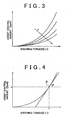
- the assist control unit 47 calculates an assist control amount Ias* with which a larger assist force is applied, as the absolute value of the steering torque ⁇ is larger and as the vehicle speed V is lower.
- FIG. 4 shows the relationship between the steering torque ⁇ and the assist control amount Ias*.
- the motor control signal output unit 46 receives the current command value I* output from the current command value calculation unit 45, and the actual current value I detected by the current sensor 43.
- the motor control signal output unit 46 executes a current feedback control so that the actual current value I is brought to the current command value I*, thereby calculating the motor control signal.
- the current command value I* and the actual current value I are input in a subtractor 49, and a deviation ⁇ I calculated by the subtractor 49 is input in a feedback control unit 50.
- the feedback control unit 50 executes a feedback control by multiplying the deviation ⁇ I by a feedback gain. As the feedback control, at least one of a proportional control and an integral control is executed.
- the feedback control unit 50 calculates a voltage command value V* by adding a proportional component obtained by multiplying the deviation ⁇ I by a proportional gain Kp to an integral component obtained by multiplying an integral value of the deviation ⁇ I by an integral gain Ki.
- a PWM control unit 51 produces a motor control signal based on the voltage command value V*
- the thus produced motor control signal is output from the microcomputer 41 to the drive circuit 42, and a drive current in accordance with the motor control signal is supplied from the drive circuit 42 to the motor 21. Then, a motor torque that corresponds to the target assist force is generated, and an assist force that corresponds to the target assist force is applied to the steering system.
- a feedback gain variable control executed in the EPS 1 according to the first embodiment will be described.
- a feedback gain calculation unit 52 is provided in the motor control signal output unit 46.
- the feedback control unit 52 executes the feedback control with the use of the proportional gain Kp and the integral gain Ki calculated by the feedback gain calculation unit 52.
- the response of the feedback control is changed by changing the proportional gain Kp and the integral gain Ki.
- the assist control unit 47 provided in the current command value calculation unit 45 outputs the assist control amount Ias* that corresponds to the basic component of the target assist force and the ratio of a change in the assist control amount Ias* to a change in the steering torque ⁇ at the time of calculation of the assist control amount Ias* (at the operating point P), that is, the assist gradient ⁇ .
- the feedback gain calculation unit 52 changes the proportional gain Kp and the integral gain Ki based on the assist gradient ⁇ , thereby changing the response of the feedback control that is executed by the feedback control unit 50.
- the feedback calculation unit 52 includes a proportional gain calculation unit 53 and an integral gain calculation unit 54.
- the proportional gain calculation unit 53 and the integral gain calculation unit 54 have a map 53a and a map 54a, respectively, in each of which the absolute value of the assist gradient ⁇ and the corresponding feedback gain (Kp, Ki) are correlated with each other.
- the proportional gain calculation unit 53 and the integral gain calculation unit 54 apply the received assist gradient ⁇ to the map 53a and the map 54a to calculate the proportional gain Kp and the integral gain Ki that correspond to the assist gradient ⁇ , respectively.
- the proportional gain Kp is linearly-interpolated between the predetermined value P0 and the predetermined value P1, more specifically, the proportional gain Kp is set to decrease from the predetermined value P0 to the predetermined value P1 with an increase in the absolute value of the assist gradient ⁇ .
- the integral gain Ki is linearly-interpolated between the predetermined value 10 and the predetermined value I1, more specifically, the integral gain Ki is set to decrease from the predetermined value I0 to the predetermined value I1 with an increase in the absolute value of the assist gradient ⁇ .
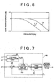
- the response of the feedback control that is executed by the feedback control unit 50 is changed as shown in FIG. 6 , by changing the proportional gain Kp and the integral gain Ki as described above. That is, when the absolute value of the assist gradient ⁇ is small (
- the feedback gains are decreased only in the case where the absolute value of the assist gradient ⁇ exceeds the predetermined threshold (predetermined value ⁇ 0), that is, only in the case where the absolute value of the assist gradient ⁇ is large ( ⁇ 0 ⁇
- predetermined value ⁇ 0 the predetermined threshold
- the predetermined threshold
- a feedback gain calculation unit 62 receives, in addition to the assist gradient ⁇ , the rotational angular speed of the steering wheel 2, that is, the steering speed ⁇ .
- the steering speed ⁇ is calculated by differentiating the steering angle detected by an existing steering sensor (not shown).
- the feedback gain calculation unit 62 executes a variable control of the feedback gains (Kp, Ki) based on the detected steering speed ⁇ .
- the noise and vibration generated during a steering operation become obvious because, for example, a housing, a body or a frame resonates when the vibration generated due to an operation of the motor 21 used as the drive source is transmitted via these members. That is, as shown in FIG. 8 , the frequency of vibration generated due to the operation of the motor 21 changes depending on the absolute value of the rotational angular speed, that is, the absolute value of the steering speed ⁇ . Then, if the frequency of the vibration generated due to the operation of the motor 21 coincides with one of the resonance frequencies of the members via which the vibration is transferred and the member resonates, an occupant in a vehicle compartment realizes the vibration and noise.
- the feedback gain calculation unit 62 decreases the feedback gains (Kp, Ki).
- the feedback gain calculation unit 62 receives the assist gradient ⁇ and the steering speed ⁇ (step 101), and determines whether the absolute value of the assist gradient ⁇ is equal to or smaller than the predetermined threshold (predetermined value ⁇ 0) (step 102).
- predetermined value ⁇ 0 the predetermined threshold
- step 104 determines whether the absolute value of the steering speed ⁇ is within the predetermined speed range that corresponds to the resonance frequency band R that is set using the resonance frequency f0 as a reference (step 104).
- the absolute value of the steering speed ⁇ is within the speed range from a value, obtained by adding ⁇ to the predetermined speed ⁇ 0 that corresponds to the resonance frequency f0, to a value, obtained by subtracting ⁇ from the predetermined speed ⁇ 0 ( ⁇ 0 ⁇ ⁇ ).
- the values that are derived through experiments or calculations and stored in the feedback gain calculation unit 62 are used as the resonance frequency f0, the predetermined speed ⁇ 0 that corresponds to the resonance frequency f0, and the predetermined value ⁇ used to define the resonance frequency band R.
- step 104 If it is determined in step 104 that the absolute value of the steering speed ⁇ is not within the predetermined speed range that corresponds to the resonance frequency band R (
- the invention is applied to the so-called column assist EPS 1.
- the invention may be applied to a so-called pinion assist EPS or a rack assist EPS.
- a brushless motor may be used as the motor that is used as the drive source.
- the feedback control unit 50 executes the proportional control and the integral control (PI control) as the feedback control.
- the feedback gain calculation unit 52 changes the proportional gain Kp and the integral gain Ki based on the assist gradient ⁇ and the steering speed ⁇ .
- the feedback control is not limited to the PI control.
- a so-called PID control that further includes a derivative control may be executed.
- the manner for changing the feedback gains is not particularly limited as long as at least one of the proportional gain Kp and the integral gain Ki is changed.
- the feedback gains are changed based on the assist gradient ⁇ in the following manner.
- the feedback gains are decreased when the absolute value of the assist gradient ⁇ exceeds the predetermined threshold.
- the manner for changing the feedback gains based on the assist gradient ⁇ is not limited to this.
- the feedback gains may be decreased continuously or in a stepwise manner with an increase in the absolute value of the assist gradient ⁇ .
- the steering speed ⁇ is calculated based on the steering angle detected by an existing steering sensor (not shown).
- the manner for calculating the steering speed ⁇ is not limited to this.
- the steering speed ⁇ may be calculated based on the steering angle obtained from the difference in wheel speed between the right wheel and the left wheel.
- the rotational angle of the motor for example, when a brushless motor is used as the motor 21 that serves as the drive source, the steering speed ⁇ may be detected based on the rotational angle of the motor.
- the steering speed ⁇ is used as a basis for determining whether resonance of the vibration due to the operation of the motor 21 occurs as described above. Accordingly, the feedback gains may be changed based on the rotational angle of the motor that is detected or estimated.
- the feedback gains (Kp, Ki) are decreased only when the absolute value of the steering speed ⁇ is within the predetermined speed range ( ⁇ 0 ⁇ ⁇ ) that corresponds to the resonance frequency band R even in the case where the absolute value of the assist gradient ⁇ is large ( ⁇ 0 ⁇
- the manner for decreasing the feedback gains (Kp, Ki) is not limited to this.
- the feedback gains (Kp, Ki) may be decreased when the absolute value of the steering speed ⁇ is within the predetermined speed range ( ⁇ 0 ⁇ ⁇ ) that corresponds to the resonance frequency band R even in the case where the absolute value of the assist gradient ⁇ is small, that is, in the case where the ripple component is less likely to be amplified.
- the feedback gains (Kp, Ki) may be decreased when the absolute value of the steering speed ⁇ is within the predetermined speed range ( ⁇ 0 ⁇ ⁇ ) that corresponds to the resonance frequency band R even in the case where the absolute value of the assist gradient ⁇ is small, that is, in the case where the ripple component is less likely to be amplified.
- the number of the steering speed (w0) that corresponds to the resonance frequency f0) is one.
- the configuration is not limited to this.
- the feedback gains may be decreased at each of the predetermined steering speeds ⁇ 1, ⁇ 2 and ⁇ 3.
- the feedback gains may be set to large values when the absolute value of the steering speed ⁇ is smaller than the predetermined steering speed ⁇ 1 that is the smallest among the steering speeds ⁇ 1, ⁇ 2, and ⁇ 3, and set to small values when the absolute value of the steering speed ⁇ is equal to or larger than the predetermined steering speed ⁇ 1 (waveform L3 in FIG.
- the feedback gains may be set to large values when the absolute value of the steering speed ⁇ is larger than the predetermined steering speed ⁇ 3 that is the largest among the steering speeds ⁇ 1, ⁇ 2, and ⁇ 3, and set to small values when the absolute value of the steering speed ⁇ is equal to or smaller than the predetermined steering speed ⁇ 3 (waveform L4 in FIG. 11 ).
- a change in the feedback gains based on the assist gradient ⁇ and a change in the feedback gains based on the steering speed ⁇ are made together (steps 103 and 105 in FIG. 9 ).
- a change in the feedback gains based on the assist gradient ⁇ and a change in the feedback gains based on the steering speed ⁇ may be made separately.
- the following method may be employed. According to this method, a decrease gain based on the assist gradient ⁇ and a decrease gain based on the steering speed ⁇ are calculated separately and then multiplied by the feedback gains.
- the feedback control includes the proportional control and the integral control, and at least one of the proportional gain and the integral gain is changed.
- a motor control signal output unit of an electric power steering system includes a feedback gain calculation unit (52), and a feedback control unit executes a feedback control with the use of a proportional gain (Kp) and an integral gain (Ki) that are calculated by the feedback gain calculation unit (52).
Landscapes
- Engineering & Computer Science (AREA)
- Chemical & Material Sciences (AREA)
- Combustion & Propulsion (AREA)
- Transportation (AREA)
- Mechanical Engineering (AREA)
- Steering Control In Accordance With Driving Conditions (AREA)
- Power Steering Mechanism (AREA)
Applications Claiming Priority (1)
| Application Number | Priority Date | Filing Date | Title |
|---|---|---|---|
| JP2009162055A JP5526630B2 (ja) | 2009-07-08 | 2009-07-08 | 電動パワーステアリング装置 |
Publications (2)
| Publication Number | Publication Date |
|---|---|
| EP2272735A1 EP2272735A1 (en) | 2011-01-12 |
| EP2272735B1 true EP2272735B1 (en) | 2014-12-24 |
Family
ID=42372287
Family Applications (1)
| Application Number | Title | Priority Date | Filing Date |
|---|---|---|---|
| EP10168731.7A Not-in-force EP2272735B1 (en) | 2009-07-08 | 2010-07-07 | Electric power steering system |
Country Status (4)
| Country | Link |
|---|---|
| US (1) | US8781682B2 (zh) |
| EP (1) | EP2272735B1 (zh) |
| JP (1) | JP5526630B2 (zh) |
| CN (1) | CN101947973B (zh) |
Families Citing this family (21)
| Publication number | Priority date | Publication date | Assignee | Title |
|---|---|---|---|---|
| KR100963967B1 (ko) * | 2008-11-19 | 2010-06-15 | 현대모비스 주식회사 | 전동식 파워스티어링 시스템의 조향 보상방법 |
| JP5569273B2 (ja) * | 2010-09-07 | 2014-08-13 | 株式会社ジェイテクト | 電動パワーステアリング装置 |
| WO2012108525A1 (ja) * | 2011-02-10 | 2012-08-16 | 株式会社ジェイテクト | 電動パワーステアリング装置およびセンサ異常検出装置 |
| JP5772137B2 (ja) * | 2011-03-28 | 2015-09-02 | 株式会社ジェイテクト | 電動パワーステアリング装置 |
| US8897965B2 (en) * | 2011-03-29 | 2014-11-25 | Jtekt Corporation | Electric power steering apparatus |
| US8818632B2 (en) * | 2012-03-30 | 2014-08-26 | Caterpillar Inc. | Detection of uncommanded motion of a steering motor |
| CN104284828B (zh) * | 2012-05-11 | 2018-08-03 | 三菱电机株式会社 | 电动助力转向装置 |
| JP2013244798A (ja) * | 2012-05-24 | 2013-12-09 | Jtekt Corp | 電動パワーステアリング装置 |
| CN104684792B (zh) * | 2013-02-07 | 2017-03-15 | 日本精工株式会社 | 电动助力转向装置 |
| WO2014122907A1 (ja) * | 2013-02-08 | 2014-08-14 | 日本精工株式会社 | 電動パワーステアリング装置 |
| JP6160860B2 (ja) * | 2013-06-11 | 2017-07-12 | 株式会社ジェイテクト | 電動パワーステアリング装置 |
| JP6201529B2 (ja) * | 2013-08-29 | 2017-09-27 | 株式会社ジェイテクト | 電動パワーステアリング装置 |
| US9358925B2 (en) | 2013-10-23 | 2016-06-07 | Jtekt Corporation | Warning device for vehicle |
| CN105246764B (zh) * | 2014-01-29 | 2017-06-23 | 日本精工株式会社 | 电动助力转向装置 |
| US9227635B1 (en) * | 2014-09-25 | 2016-01-05 | Nissan North America, Inc. | Method and system of assisting a driver of a vehicle |
| JP2016088436A (ja) * | 2014-11-10 | 2016-05-23 | 株式会社デンソー | モータ制御装置 |
| US9561820B2 (en) * | 2015-06-30 | 2017-02-07 | Caterpillar Paving Products Inc. | Uncommanded steering detection |
| JP6641595B2 (ja) * | 2016-02-15 | 2020-02-05 | 株式会社ジェイテクト | 車両用警報装置 |
| JP6495877B2 (ja) * | 2016-10-12 | 2019-04-03 | 本田技研工業株式会社 | 電圧変換装置及び機器 |
| US10960924B2 (en) * | 2017-06-16 | 2021-03-30 | Toyota Research Institute, Inc. | Vehicle systems for adjusting resistance or sensitivity of steering wheels and/or accelerator pedals |
| JP7420128B2 (ja) | 2021-10-19 | 2024-01-23 | トヨタ自動車株式会社 | ステアリングシステム |
Family Cites Families (15)
| Publication number | Priority date | Publication date | Assignee | Title |
|---|---|---|---|---|
| JP3231932B2 (ja) | 1994-01-10 | 2001-11-26 | 本田技研工業株式会社 | 電動式パワーステアリング装置 |
| JP3625662B2 (ja) * | 1998-10-05 | 2005-03-02 | 三菱電機株式会社 | 電動パワーステアリング装置 |
| JP3719085B2 (ja) | 2000-02-29 | 2005-11-24 | 豊田工機株式会社 | 電気式動力舵取装置 |
| JP4660883B2 (ja) * | 2000-05-24 | 2011-03-30 | 日本精工株式会社 | 電動パワーステアリング装置の制御装置 |
| JP4670161B2 (ja) * | 2000-07-13 | 2011-04-13 | マツダ株式会社 | 自動車の電動パワーステアリング装置 |
| JP4089435B2 (ja) * | 2003-01-08 | 2008-05-28 | 株式会社ジェイテクト | 電動パワーステアリング装置 |
| JP4120427B2 (ja) * | 2003-03-06 | 2008-07-16 | トヨタ自動車株式会社 | 車輌用操舵制御装置 |
| JP2005170283A (ja) * | 2003-12-12 | 2005-06-30 | Toyota Motor Corp | 電動パワーステアリング装置 |
| JP4412006B2 (ja) * | 2004-03-05 | 2010-02-10 | 株式会社ジェイテクト | 電動パワーステアリング装置 |
| EP1616774A3 (en) | 2004-07-15 | 2007-08-08 | NSK Ltd., | Electric power steering apparatus |
| JP4639759B2 (ja) | 2004-11-09 | 2011-02-23 | 株式会社ジェイテクト | 電動パワーステアリング装置 |
| JP4367383B2 (ja) * | 2005-07-08 | 2009-11-18 | トヨタ自動車株式会社 | 車両の操舵アシスト装置 |
| EP2026458A1 (en) * | 2006-05-31 | 2009-02-18 | NSK Ltd. | Electric power steering device |
| JP2008006919A (ja) | 2006-06-28 | 2008-01-17 | Toyota Motor Corp | 電動パワーステアリング装置 |
| JP5194716B2 (ja) | 2007-10-30 | 2013-05-08 | 株式会社ジェイテクト | 電動パワーステアリング装置 |
-
2009
- 2009-07-08 JP JP2009162055A patent/JP5526630B2/ja not_active Expired - Fee Related
-
2010
- 2010-07-01 US US12/828,509 patent/US8781682B2/en not_active Expired - Fee Related
- 2010-07-06 CN CN201010224611.6A patent/CN101947973B/zh not_active Expired - Fee Related
- 2010-07-07 EP EP10168731.7A patent/EP2272735B1/en not_active Not-in-force
Also Published As
| Publication number | Publication date |
|---|---|
| US20110010050A1 (en) | 2011-01-13 |
| JP5526630B2 (ja) | 2014-06-18 |
| CN101947973A (zh) | 2011-01-19 |
| US8781682B2 (en) | 2014-07-15 |
| CN101947973B (zh) | 2014-10-29 |
| JP2011016435A (ja) | 2011-01-27 |
| EP2272735A1 (en) | 2011-01-12 |
Similar Documents
| Publication | Publication Date | Title |
|---|---|---|
| EP2272735B1 (en) | Electric power steering system | |
| EP1808359B1 (en) | Electric power steering apparatus | |
| EP2933169B1 (en) | Electric power steering apparatus | |
| JP4852964B2 (ja) | 電動パワーステアリング装置の制御装置 | |
| EP1878638B1 (en) | Control apparatus for electric power steering | |
| JP5327331B2 (ja) | 車両の電動パワーステアリング装置 | |
| US7873453B2 (en) | Control apparatus for electric power steering apparatus | |
| EP2900542B1 (en) | Steering control system for vehicle and steering control method for vehicle | |
| US7909131B2 (en) | Electric power steering apparatus | |
| EP2116443B1 (en) | Electric power steering apparatus | |
| JP5313729B2 (ja) | 電動パワーステアリング装置 | |
| US9688307B2 (en) | Electric power steering controller | |
| WO2009128466A1 (ja) | 電動パワーステアリング装置及びその制御方法 | |
| JP5074971B2 (ja) | 車両用操舵装置 | |
| US8838340B2 (en) | Electric power steering system | |
| JP6387657B2 (ja) | 電動パワーステアリング制御装置 | |
| JP4404688B2 (ja) | 車両の走行状態制御装置 | |
| JP2008074269A (ja) | 車両のロールオーバ制御装置 | |
| JP2005088666A (ja) | 電動パワーステアリング装置 | |
| JP5025686B2 (ja) | 車両挙動制御装置 | |
| JP5040414B2 (ja) | 電動パワーステアリング装置の制御装置 | |
| JP2009286350A (ja) | 電動パワーステアリング装置の制御装置 | |
| JP2010030431A (ja) | 電動パワーステアリング装置の制御装置 |
Legal Events
| Date | Code | Title | Description |
|---|---|---|---|
| PUAI | Public reference made under article 153(3) epc to a published international application that has entered the european phase |
Free format text: ORIGINAL CODE: 0009012 |
|
| AK | Designated contracting states |
Kind code of ref document: A1 Designated state(s): AL AT BE BG CH CY CZ DE DK EE ES FI FR GB GR HR HU IE IS IT LI LT LU LV MC MK MT NL NO PL PT RO SE SI SK SM TR |
|
| AX | Request for extension of the european patent |
Extension state: BA ME RS |
|
| 17P | Request for examination filed |
Effective date: 20110712 |
|
| RIC1 | Information provided on ipc code assigned before grant |
Ipc: B62D 5/04 20060101AFI20130625BHEP |
|
| GRAP | Despatch of communication of intention to grant a patent |
Free format text: ORIGINAL CODE: EPIDOSNIGR1 |
|
| INTG | Intention to grant announced |
Effective date: 20131202 |
|
| GRAP | Despatch of communication of intention to grant a patent |
Free format text: ORIGINAL CODE: EPIDOSNIGR1 |
|
| INTG | Intention to grant announced |
Effective date: 20140917 |
|
| GRAS | Grant fee paid |
Free format text: ORIGINAL CODE: EPIDOSNIGR3 |
|
| GRAA | (expected) grant |
Free format text: ORIGINAL CODE: 0009210 |
|
| AK | Designated contracting states |
Kind code of ref document: B1 Designated state(s): AL AT BE BG CH CY CZ DE DK EE ES FI FR GB GR HR HU IE IS IT LI LT LU LV MC MK MT NL NO PL PT RO SE SI SK SM TR |
|
| REG | Reference to a national code |
Ref country code: GB Ref legal event code: FG4D |
|
| REG | Reference to a national code |
Ref country code: CH Ref legal event code: EP |
|
| REG | Reference to a national code |
Ref country code: IE Ref legal event code: FG4D |
|
| REG | Reference to a national code |
Ref country code: AT Ref legal event code: REF Ref document number: 702971 Country of ref document: AT Kind code of ref document: T Effective date: 20150115 |
|
| REG | Reference to a national code |
Ref country code: DE Ref legal event code: R096 Ref document number: 602010021224 Country of ref document: DE Effective date: 20150219 |
|
| REG | Reference to a national code |
Ref country code: NL Ref legal event code: VDEP Effective date: 20141224 |
|
| PG25 | Lapsed in a contracting state [announced via postgrant information from national office to epo] |
Ref country code: FI Free format text: LAPSE BECAUSE OF FAILURE TO SUBMIT A TRANSLATION OF THE DESCRIPTION OR TO PAY THE FEE WITHIN THE PRESCRIBED TIME-LIMIT Effective date: 20141224 Ref country code: LT Free format text: LAPSE BECAUSE OF FAILURE TO SUBMIT A TRANSLATION OF THE DESCRIPTION OR TO PAY THE FEE WITHIN THE PRESCRIBED TIME-LIMIT Effective date: 20141224 Ref country code: NO Free format text: LAPSE BECAUSE OF FAILURE TO SUBMIT A TRANSLATION OF THE DESCRIPTION OR TO PAY THE FEE WITHIN THE PRESCRIBED TIME-LIMIT Effective date: 20150324 |
|
| REG | Reference to a national code |
Ref country code: LT Ref legal event code: MG4D |
|
| PG25 | Lapsed in a contracting state [announced via postgrant information from national office to epo] |
Ref country code: GR Free format text: LAPSE BECAUSE OF FAILURE TO SUBMIT A TRANSLATION OF THE DESCRIPTION OR TO PAY THE FEE WITHIN THE PRESCRIBED TIME-LIMIT Effective date: 20150325 Ref country code: LV Free format text: LAPSE BECAUSE OF FAILURE TO SUBMIT A TRANSLATION OF THE DESCRIPTION OR TO PAY THE FEE WITHIN THE PRESCRIBED TIME-LIMIT Effective date: 20141224 Ref country code: HR Free format text: LAPSE BECAUSE OF FAILURE TO SUBMIT A TRANSLATION OF THE DESCRIPTION OR TO PAY THE FEE WITHIN THE PRESCRIBED TIME-LIMIT Effective date: 20141224 Ref country code: SE Free format text: LAPSE BECAUSE OF FAILURE TO SUBMIT A TRANSLATION OF THE DESCRIPTION OR TO PAY THE FEE WITHIN THE PRESCRIBED TIME-LIMIT Effective date: 20141224 |
|
| REG | Reference to a national code |
Ref country code: AT Ref legal event code: MK05 Ref document number: 702971 Country of ref document: AT Kind code of ref document: T Effective date: 20141224 |
|
| PG25 | Lapsed in a contracting state [announced via postgrant information from national office to epo] |
Ref country code: NL Free format text: LAPSE BECAUSE OF FAILURE TO SUBMIT A TRANSLATION OF THE DESCRIPTION OR TO PAY THE FEE WITHIN THE PRESCRIBED TIME-LIMIT Effective date: 20141224 |
|
| PG25 | Lapsed in a contracting state [announced via postgrant information from national office to epo] |
Ref country code: CZ Free format text: LAPSE BECAUSE OF FAILURE TO SUBMIT A TRANSLATION OF THE DESCRIPTION OR TO PAY THE FEE WITHIN THE PRESCRIBED TIME-LIMIT Effective date: 20141224 Ref country code: RO Free format text: LAPSE BECAUSE OF FAILURE TO SUBMIT A TRANSLATION OF THE DESCRIPTION OR TO PAY THE FEE WITHIN THE PRESCRIBED TIME-LIMIT Effective date: 20141224 Ref country code: SK Free format text: LAPSE BECAUSE OF FAILURE TO SUBMIT A TRANSLATION OF THE DESCRIPTION OR TO PAY THE FEE WITHIN THE PRESCRIBED TIME-LIMIT Effective date: 20141224 Ref country code: EE Free format text: LAPSE BECAUSE OF FAILURE TO SUBMIT A TRANSLATION OF THE DESCRIPTION OR TO PAY THE FEE WITHIN THE PRESCRIBED TIME-LIMIT Effective date: 20141224 Ref country code: ES Free format text: LAPSE BECAUSE OF FAILURE TO SUBMIT A TRANSLATION OF THE DESCRIPTION OR TO PAY THE FEE WITHIN THE PRESCRIBED TIME-LIMIT Effective date: 20141224 |
|
| PG25 | Lapsed in a contracting state [announced via postgrant information from national office to epo] |
Ref country code: AT Free format text: LAPSE BECAUSE OF FAILURE TO SUBMIT A TRANSLATION OF THE DESCRIPTION OR TO PAY THE FEE WITHIN THE PRESCRIBED TIME-LIMIT Effective date: 20141224 Ref country code: IS Free format text: LAPSE BECAUSE OF FAILURE TO SUBMIT A TRANSLATION OF THE DESCRIPTION OR TO PAY THE FEE WITHIN THE PRESCRIBED TIME-LIMIT Effective date: 20150424 Ref country code: PL Free format text: LAPSE BECAUSE OF FAILURE TO SUBMIT A TRANSLATION OF THE DESCRIPTION OR TO PAY THE FEE WITHIN THE PRESCRIBED TIME-LIMIT Effective date: 20141224 |
|
| REG | Reference to a national code |
Ref country code: DE Ref legal event code: R097 Ref document number: 602010021224 Country of ref document: DE |
|
| PG25 | Lapsed in a contracting state [announced via postgrant information from national office to epo] |
Ref country code: DK Free format text: LAPSE BECAUSE OF FAILURE TO SUBMIT A TRANSLATION OF THE DESCRIPTION OR TO PAY THE FEE WITHIN THE PRESCRIBED TIME-LIMIT Effective date: 20141224 |
|
| PLBE | No opposition filed within time limit |
Free format text: ORIGINAL CODE: 0009261 |
|
| STAA | Information on the status of an ep patent application or granted ep patent |
Free format text: STATUS: NO OPPOSITION FILED WITHIN TIME LIMIT |
|
| 26N | No opposition filed |
Effective date: 20150925 |
|
| PG25 | Lapsed in a contracting state [announced via postgrant information from national office to epo] |
Ref country code: IT Free format text: LAPSE BECAUSE OF FAILURE TO SUBMIT A TRANSLATION OF THE DESCRIPTION OR TO PAY THE FEE WITHIN THE PRESCRIBED TIME-LIMIT Effective date: 20141224 |
|
| PG25 | Lapsed in a contracting state [announced via postgrant information from national office to epo] |
Ref country code: SI Free format text: LAPSE BECAUSE OF FAILURE TO SUBMIT A TRANSLATION OF THE DESCRIPTION OR TO PAY THE FEE WITHIN THE PRESCRIBED TIME-LIMIT Effective date: 20141224 Ref country code: MC Free format text: LAPSE BECAUSE OF FAILURE TO SUBMIT A TRANSLATION OF THE DESCRIPTION OR TO PAY THE FEE WITHIN THE PRESCRIBED TIME-LIMIT Effective date: 20141224 |
|
| REG | Reference to a national code |
Ref country code: CH Ref legal event code: PL |
|
| GBPC | Gb: european patent ceased through non-payment of renewal fee |
Effective date: 20150707 |
|
| PG25 | Lapsed in a contracting state [announced via postgrant information from national office to epo] |
Ref country code: LU Free format text: LAPSE BECAUSE OF FAILURE TO SUBMIT A TRANSLATION OF THE DESCRIPTION OR TO PAY THE FEE WITHIN THE PRESCRIBED TIME-LIMIT Effective date: 20150707 |
|
| REG | Reference to a national code |
Ref country code: IE Ref legal event code: MM4A |
|
| PG25 | Lapsed in a contracting state [announced via postgrant information from national office to epo] |
Ref country code: GB Free format text: LAPSE BECAUSE OF NON-PAYMENT OF DUE FEES Effective date: 20150707 Ref country code: CH Free format text: LAPSE BECAUSE OF NON-PAYMENT OF DUE FEES Effective date: 20150731 Ref country code: LI Free format text: LAPSE BECAUSE OF NON-PAYMENT OF DUE FEES Effective date: 20150731 |
|
| PG25 | Lapsed in a contracting state [announced via postgrant information from national office to epo] |
Ref country code: BE Free format text: LAPSE BECAUSE OF FAILURE TO SUBMIT A TRANSLATION OF THE DESCRIPTION OR TO PAY THE FEE WITHIN THE PRESCRIBED TIME-LIMIT Effective date: 20141224 |
|
| REG | Reference to a national code |
Ref country code: FR Ref legal event code: PLFP Year of fee payment: 7 |
|
| PG25 | Lapsed in a contracting state [announced via postgrant information from national office to epo] |
Ref country code: IE Free format text: LAPSE BECAUSE OF NON-PAYMENT OF DUE FEES Effective date: 20150707 |
|
| PG25 | Lapsed in a contracting state [announced via postgrant information from national office to epo] |
Ref country code: MT Free format text: LAPSE BECAUSE OF FAILURE TO SUBMIT A TRANSLATION OF THE DESCRIPTION OR TO PAY THE FEE WITHIN THE PRESCRIBED TIME-LIMIT Effective date: 20141224 |
|
| PG25 | Lapsed in a contracting state [announced via postgrant information from national office to epo] |
Ref country code: SM Free format text: LAPSE BECAUSE OF FAILURE TO SUBMIT A TRANSLATION OF THE DESCRIPTION OR TO PAY THE FEE WITHIN THE PRESCRIBED TIME-LIMIT Effective date: 20141224 Ref country code: HU Free format text: LAPSE BECAUSE OF FAILURE TO SUBMIT A TRANSLATION OF THE DESCRIPTION OR TO PAY THE FEE WITHIN THE PRESCRIBED TIME-LIMIT; INVALID AB INITIO Effective date: 20100707 Ref country code: BG Free format text: LAPSE BECAUSE OF FAILURE TO SUBMIT A TRANSLATION OF THE DESCRIPTION OR TO PAY THE FEE WITHIN THE PRESCRIBED TIME-LIMIT Effective date: 20141224 |
|
| REG | Reference to a national code |
Ref country code: FR Ref legal event code: PLFP Year of fee payment: 8 |
|
| PG25 | Lapsed in a contracting state [announced via postgrant information from national office to epo] |
Ref country code: CY Free format text: LAPSE BECAUSE OF FAILURE TO SUBMIT A TRANSLATION OF THE DESCRIPTION OR TO PAY THE FEE WITHIN THE PRESCRIBED TIME-LIMIT Effective date: 20141224 |
|
| PG25 | Lapsed in a contracting state [announced via postgrant information from national office to epo] |
Ref country code: TR Free format text: LAPSE BECAUSE OF FAILURE TO SUBMIT A TRANSLATION OF THE DESCRIPTION OR TO PAY THE FEE WITHIN THE PRESCRIBED TIME-LIMIT Effective date: 20141224 |
|
| REG | Reference to a national code |
Ref country code: FR Ref legal event code: PLFP Year of fee payment: 9 |
|
| PG25 | Lapsed in a contracting state [announced via postgrant information from national office to epo] |
Ref country code: MK Free format text: LAPSE BECAUSE OF FAILURE TO SUBMIT A TRANSLATION OF THE DESCRIPTION OR TO PAY THE FEE WITHIN THE PRESCRIBED TIME-LIMIT Effective date: 20141224 |
|
| PG25 | Lapsed in a contracting state [announced via postgrant information from national office to epo] |
Ref country code: PT Free format text: LAPSE BECAUSE OF FAILURE TO SUBMIT A TRANSLATION OF THE DESCRIPTION OR TO PAY THE FEE WITHIN THE PRESCRIBED TIME-LIMIT Effective date: 20141224 |
|
| PG25 | Lapsed in a contracting state [announced via postgrant information from national office to epo] |
Ref country code: AL Free format text: LAPSE BECAUSE OF FAILURE TO SUBMIT A TRANSLATION OF THE DESCRIPTION OR TO PAY THE FEE WITHIN THE PRESCRIBED TIME-LIMIT Effective date: 20141224 |
|
| PGFP | Annual fee paid to national office [announced via postgrant information from national office to epo] |
Ref country code: FR Payment date: 20200611 Year of fee payment: 11 |
|
| PGFP | Annual fee paid to national office [announced via postgrant information from national office to epo] |
Ref country code: DE Payment date: 20200624 Year of fee payment: 11 |
|
| REG | Reference to a national code |
Ref country code: DE Ref legal event code: R119 Ref document number: 602010021224 Country of ref document: DE |
|
| PG25 | Lapsed in a contracting state [announced via postgrant information from national office to epo] |
Ref country code: DE Free format text: LAPSE BECAUSE OF NON-PAYMENT OF DUE FEES Effective date: 20220201 |
|
| PG25 | Lapsed in a contracting state [announced via postgrant information from national office to epo] |
Ref country code: FR Free format text: LAPSE BECAUSE OF NON-PAYMENT OF DUE FEES Effective date: 20210731 |