EP2272710A2 - Sitzvorrichtung für ein Fahrzeug und Verfahren zu ihrer Bereitstellung - Google Patents
Sitzvorrichtung für ein Fahrzeug und Verfahren zu ihrer Bereitstellung Download PDFInfo
- Publication number
- EP2272710A2 EP2272710A2 EP10006724A EP10006724A EP2272710A2 EP 2272710 A2 EP2272710 A2 EP 2272710A2 EP 10006724 A EP10006724 A EP 10006724A EP 10006724 A EP10006724 A EP 10006724A EP 2272710 A2 EP2272710 A2 EP 2272710A2
- Authority
- EP
- European Patent Office
- Prior art keywords
- seat
- sub
- webbing
- main
- retractor
- Prior art date
- Legal status (The legal status is an assumption and is not a legal conclusion. Google has not performed a legal analysis and makes no representation as to the accuracy of the status listed.)
- Granted
Links
Images


Classifications
-
- B—PERFORMING OPERATIONS; TRANSPORTING
- B60—VEHICLES IN GENERAL
- B60N—SEATS SPECIALLY ADAPTED FOR VEHICLES; VEHICLE PASSENGER ACCOMMODATION NOT OTHERWISE PROVIDED FOR
- B60N2/00—Seats specially adapted for vehicles; Arrangement or mounting of seats in vehicles
- B60N2/68—Seat frames
- B60N2/688—Particular seat belt attachment and guiding
-
- B—PERFORMING OPERATIONS; TRANSPORTING
- B60—VEHICLES IN GENERAL
- B60R—VEHICLES, VEHICLE FITTINGS, OR VEHICLE PARTS, NOT OTHERWISE PROVIDED FOR
- B60R22/00—Safety belts or body harnesses in vehicles
- B60R22/18—Anchoring devices
- B60R22/26—Anchoring devices secured to the seat
-
- B—PERFORMING OPERATIONS; TRANSPORTING
- B60—VEHICLES IN GENERAL
- B60R—VEHICLES, VEHICLE FITTINGS, OR VEHICLE PARTS, NOT OTHERWISE PROVIDED FOR
- B60R22/00—Safety belts or body harnesses in vehicles
- B60R22/18—Anchoring devices
- B60R22/26—Anchoring devices secured to the seat
- B60R2022/263—Front seats
Definitions
- the present invention relates to a seat device for a vehicle and to a method of providing it, the seat device comprising a main seat having a main-seat cushion and a main-seat back, and a sub seat having a sub-seat cushion and a sub-seat back, wherein the sub-seat back is supported at the main-seat back via a sub-seat back support member so as to be foldable at the main-seat back.
- a seat device for a vehicle which comprises a second-row rear seat having a pair of main seats and a sub seat provided between them.
- this seat device may provide various seat arrangements, such as a two-passenger mode in which two passengers can be seated serenely in a wide seat space formed by the main seats and the sub seat, a three-passenger mode in which three passengers can be seated in the main seats and the sub seat, a walk-through mode in which the sub seat is stored at either one of the main seats so that a walk-in space can be formed between the second-row seat and a third-row seat, or some use mode in which the sub-seat cushion is used as a container, or the sub-seat back is used as a cup holder.
- the above-described sub seat (assist seat) may be necessary to be made with a light weight because it is foldable at the main seat, and it may not have enough strength to attach a seatbelt for the sub seat. Accordingly, a two-point type of seatbelt for the sub seat is practically provided at the main seat beside the sub seat to restrain the passenger seated in the sub seat. However, it is preferable that a three-point type of seatbelt be provided for the sub seat, and in this case it may be considered that a shoulder anchor to guide the seatbelt for the sub seat is provided on the side of the seat back of the main seat.
- Japanese Patent Laid-Open Publication No. 2004-249782 discloses the seat device for a vehicle comprising the main seat and the sub seat, in which the seat back of the sub seat is attached to the seat back of the main seat via the horizontal axis so as to rotate in the vehicle longitudinal direction. Further, the seat back of the sub seat is attached to the seat back of the main seat via the vertical axis so as to be folded. Moreover, the seat cushion of the sub seat can provide either its sitting state or its storage state.
- This publication discloses nothing about a seatbelt device for a sub seat which comprises a webbing, retractor and so on.
- Japanese Patent Laid-Open Publication No. 11-129800 discloses the three-point type of seatbelt applied to the sub seat.
- the seat cushion of the sub seat is supported at the seat cushion of the main seat
- the seat back of the sub seat is attached to the seat cushion of the sub seat. Accordingly, there was a problem in that the rigidity of the sub seat may be insufficient, so that the sitting feeling would deteriorate. Further, since the shoulder anchor of the seatbelt for the sub seat is attached to the seat back of the main seat, there was the same problem described above.
- An object of the present invention is to ensure the sufficient sitting rigidity of the sub seat and the proper support rigidity of the retractor.
- a seat device for a vehicle comprising a sub seat having a sub-seat cushion and a sub-seat back, the sub-seat cushion to be supported at a main seat so as to be storable at a position at least partly below a main-seat cushion of the main seat, the sub-seat back supporting a back of a passenger seated in the sub seat, a sub-seat back support member to support the sub-seat back at the main-seat back so that the sub-seat back is foldable at the main-seat back, and a seatbelt device for a sub seat, the seatbelt device for a sub seat comprising a retractor to wind up a webbing and a buckle to detachably hold a tongue provided at the webbing, wherein the retractor of the seatbelt device for a sub seat is attached to the sub-seat back support member, and the buckle of the seatbelt device for a sub seat is provided on a side of the sub-seat
- the sub-seat cushion is supported at the main seat and the sub-seat back is supported at the main-seat back, the sufficient sitting rigidity of the sub seat can be endured, and thereby the comfortable sitting can be provided. Further, since the retractor of the seatbelt device for the sub seat is attached to the sub-seat back support member, the sufficient support rigidity of the retractor can be ensured. Moreover, the passenger seated in the sub seat can be properly restrained by the webbing when the tongue fixed to the webbing is held by the buckle of the sub-seat cushion.
- the seat device further comprises the main seat having a main-seat cushion and a main-seat back, the main-seat back projecting substantially upward from the main-seat cushion, particularly from a rear end of the main-seat cushion, to support a back of a passenger seated in the main seat.
- a shoulder anchor to guide a middle or intermediate portion of the webbing of the seatbelt device for a sub seat is attached to an upper portion of the sub-seat back support member which is positioned above the retractor of the seatbelt device for a sub seat.
- the retractor of the seatbelt device for a sub seat is provided at or near an upper portion of the sub-seat back support member, an end portion of the webbing extending from the retractor is fixed to the sub-seat back support member at a height position which substantially corresponds to the sub-seat cushion, and the tongue detachably held by the buckle is provided movably at a middle or intermediate portion of the webbing of the seatbelt device for a sub seat.
- the end portion of the webbing is fixed to the sub-seat back support member and the tongue is provided movably at the middle or intermediate portion of the webbing, the passenger seated in the sub seat can be restrained by the three-point type of seatbelt properly when the tongue is held by the buckle.
- the retractor is provided at the height position which corresponds to the passenger's shoulder, any too-much longitudinal move of the upper half body of the passenger which may be caused by the vehicle collision can be properly prevented by the lock mechanism of the webbing by the retractor, so that the safety of the passenger seated in the sub seat can be further improved.
- the retractor is provided at the sub-seat back support member, the proper support rigidity of the retractor can be ensured.
- the retractor of the seatbelt device for a sub seat is provided at an upper portion of the sub-seat back support member, the tongue is provided movably at a middle or intermediate portion of the webbing detachably held by the buckle of the seatbelt device for a sub seat, and a fixed tongue detachably held by another buckle which is provided on the other side of the sub-seat cushion which is substantially opposite to a disposition side of the buckle is fixed to an end portion of the webbing.
- the safety of the passenger seated in the sub seat can be improved. Further, since a so-called double tongue constitution is provided, the webbing can be perfectly wound up by and stored in the retractor in a seat arranging, so that the proper seat arrangement can be obtained. Moreover, since the retractor is provided at the sub-seat back support member, the proper support rigidity of the retractor can be ensured.
- the buckle is provided at the sub-seat cushion of the sub seat.
- the buckle can be stored along with the sub-seat cushion below the main-seat cushion, so the proper appearance in a storage state can be provided.
- the sub-seat back support member is supported at a seat-back frame of the main seat.
- the support rigidity of the retractor attached to the sub-seat back support member (or, the retractor and the shoulder anchor) can be further improved, so that the crash from the vehicle collision can be received properly.
- the sub-seat back support member comprises a frame support portion and an attachment portion supporting the frame support portion at the main seat so that the frame support portion can rotate or pivot.
- the sub-seat back support member supports the sub-seat back so as to be foldable at the main-seat back.
- said retractor of the seatbelt device for a sub seat is attached to said sub-seat back support member via at least one bracket.
- a sub-seat cushion of the sub seat is includes a sub-seat cushion frame being attached to a support portion which is provided on a side of a seat-cushion support bracket of the main seat via at least one support bracket.
- a method of providing or mounting or assembling a seat device in a vehicle comprising the following steps:
- the method further comprises attaching a shoulder anchor to guide an intermediate portion of the webbing of said seatbelt device for a sub seat to an upper portion of said sub-seat back support member which is positioned above said retractor of the seatbelt device for a sub seat.
- said retractor of the seatbelt device for a sub seat is provided at an upper portion of said sub-seat back support member, an end portion of the webbing extending from the retractor is fixed to said sub-seat back support member at a height position which substantially corresponds to said sub-seat cushion, and said tongue detachably held by the buckle is provided movably at a intermediate portion of the webbing of the seatbelt device for a sub seat.
- said retractor of the seatbelt device for a sub seat is provided at an upper portion of said sub-seat back support member, said tongue is provided movably at a intermediate portion of the webbing detachably held by the buckle of the seatbelt device for a sub seat, and a fixed tongue detachably held by another buckle which is provided on the other side of the sub-seat cushion which is substantially opposite to a disposition side of said buckle is fixed to an end portion of the webbing.
- said buckle is provided at said sub-seat cushion of the sub seat.
- a seat device for a vehicle comprises lateral (left and right) main seats M1, M2 and a sub seat S which is positioned between the main seats M1, M2.
- this seat device for a vehicle is particularly applicable to a second-row rear seat of the vehicle.
- the left-side seat M1 will be described mainly because these two seats have substantially the same structure.
- the same reference characters are used for the right-side seat M2 as well.
- a (substantially horizontal) floor panel 1 is provided to form a bottom face of a vehicle compartment.
- a pair of seat slide rails 2, 2 which extend substantially in a vehicle longitudinal direction and away or spaced from each other in a vehicle width direction.
- the above-described main seat M1 has a main-seat cushion 5 and a main-seat back 6 which projects substantially upward from (preferably substantially a rear end of) the main-seat cushion 5 to support a back of a passenger seated in the main seat M1.
- a main-seat cushion frame 7 is arranged at least partly inside the main-seat cushion 5. Both sides of a lower portion of the main-seat cushion frame 7 are to be connected to upper rails 4 via substantially L-shaped seat-cushion support bracket 8, 8.
- Seat-cushion frame sides 9, 9 which extend substantially in the longitudinal direction are provided at or near outside portions of the seat-cushion support bracket 8, 8.
- Reclining support brackets 10, 10 which project substantially upward toward a lower portion of the main-seat back 6 are attached to rear sides of the seat-cushion frame sides 9, 9.
- a reclining axis 11 which substantially extends in the vehicle width direction is provided between the reclining support brackets 10, 10.
- the main-seat back 6 includes a (preferably substantially rectangular) main-seat back frame 12 and seat-back frame sides 13, 13 which are to be fixed to the both sides of this frame 12.
- the seat-back frame sides 13, 13 substantially extend downward toward the reclining axis 11, and their lower extending portions of these frame sides 13, 13 are provided at or close to the reclining axis 11.
- the reclining operation of the main-seat back 6 particularly is available with a reclining device, not illustrated.
- the lateral (left and right) main seats M1, M2 can substantially slide in the vehicle longitudinal direction along the seat slide tails 2, and each main-seat back 6 of these seats M1, M2 can recline around the reclining axis 11.
- This sub seat S has a sub-seat cushion 20 and a sub-seat back 21.
- the sub-seat cushion 20 is storable in the above-described storage portion 14 at least partly below the main-seat cushion 5, and the sub-seat back 21 supports a back of a passenger seated in the sub seat S.
- a sub-seat back frame support portion 22 (hereinafter, referred to as a "frame support portion") which extends substantially vertically is provided at least partly inside the sub-seat back 21 near the left-side main seat M1.
- This sub-seat back frame support portion 22 is made e.g. of a metal circular pipe for the purpose of its light weight and/or sufficient rigidity.
- a (preferably substantially drum-shaped) attachment portion 23 is provided at or near a lower extension of the frame support portion 22. This attachment portion 23 supports the frame support portion 22 at the main seat M1, and as shown in FIG. 2 (a perspective view taken along line A-A of FIG. 1 ), preferably is substantially formed in a hollow drum shape.
- An upper-end neck portion 23a of the attachment portion 23 supports the frame support portion 22 so that the frame support portion 22 can rotate or pivot.
- a sub-seat back frame 25 is attached to the above-described frame support portion 22 with one or more attachments 24, 24.
- the sub-seat back frame 25 preferably is made of a metal circular pipe for its light weight and sufficient rigidity.
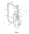
- the sub-seat back frame 25, as shown in FIG. 3 comprises an upper piece 25a which extends from the upper attachment 24 laterally (toward the right), a right piece 25b which extends vertically from a right end of the upper piece 25a, a lower piece 25c which extends from a lower end of the right piece 25b laterally (toward the left), a left piece 25d which extends upward from a left end of the lower piece to a position which corresponds to the lower attachment 24, and an attachment piece 25e which extends from an upper end of the left piece 25d laterally (toward the left) and connects to the lower attachment 24.
- the above-described frame support portion 22 and attachment portion 23 constitute or form part of a sub-seat back support member 26, which particularly is to be stored inside the sub-seat back 21 in the elevation view of the vehicle so as to form part of the sub-seat back 21.
- This sub-seat back support member 26 supports the sub-seat back 21 so as to be foldable at the main-seat back 6.
- the attachment portion 23 of the sub-seat back support member 26 is to be supported at the seat-back frame side 13 inside the left-side main-seat back 6 preferably via a rotational center axis 27 and a sub-seat fixing bracket 28.
- the above-described sub-seat fixing bracket 28 is to be supported at the pair of seat-back frame sides 13, 13.
- the above-described sub-seat fixing bracket 28 is fixed to the right-side seat-back frame side 13, the above-described rotational center axis 27 is attached to the sub-seat fixing bracket 28, and the attachment portion 23 is rotatable or pivotable substantially in the vehicle longitudinal direction around the rotational center axis 27.
- an outer periphery of the attachment portion 23 is covered with a cover member 29.
- the frame support portion 22 Since the frame support portion 22 is supported at the upper neck portion 23a of the attachment portion 23 (see FiG. 2 ) so as to rotate or pivot as shown in the perspective view of FIG. 3 , the frame support portion 22, sub-seat back frame 25, and sub-seat back 21 rotate or pivot together as shown by an arrow a of FIG. 3 , so that the sub-seat back 21 is foldable at the main-seat back 6.
- the attachment portion 23 (see FIG. 2 ) preferably is supported so as to rotate or pivot around the rotational center axis 27, the sub-seat back support member 26 which is comprised of this attachment portion 23 and the frame support portion 22 rotate or pivot together with the sub-seat back frame 25 and the sub-seat back 21 as shown by an arrow b in FIG. 3 .
- the sub-seat back 21 is configured to rotate or pivot in the vehicle longitudinal direction relative to the main-seat back 6.
- a retractor 31 is attached below or adjacent to the attachment portion 23 via a bracket 30.
- This retractor 31 constitutes or forms part of a seatbelt device X for the sub seat S and winds up a webbing 32 of the seatbelt device X.
- the retractor 31 is attached firmly to the sub-seat support member 26 preferably via the bracket 30 and one or more attaching members such as bolts 31 B, 31 B, so that the bracket 30 can be prevented from moving by a load which the retractor 31 receives.
- a second bracket 302 which at least partly encloses the retractor 31 and/or fixes the retractor 31 to the bracket 30 is provided.
- the bracket 30 is fixed with the bolts 31 B, 31 B in the above-described embodiment. This is just because using the bolts 31 B, 31 B may have an advantage that the bracket 30 and the retractor 31 can be used commonly even in case the size of the seats is different. Accordingly, another connection means for fixing of the bracket 30, such as welding, may be applied in place of the bolts 31 B.
- a tip tongue 33 is fixed to a distal portion (such as a tip) of the webbing 32. Further, a webbing outlet 34 from which the webbing 32 is withdrawn is formed at a specified (predetermined or predeterminable) portion (a left lower portion according to the present embodiment) of the sub-seat back 21 which substantially corresponds to the retractor 31.
- the sub-seat cushion 20 of the sub seat S is constituted or formed as shown in FIGS. 2 and 4 .
- the sub-seat cushion 20 includes a sub-seat cushion frame 35 which preferably is made of a (preferably metal) circular pipe and/or substantially has a rectangular shape, and a plate 36 which is fixed to an upper portion of the sub-seat cushion frame 35 and preferably has a substantially flat plate shape in it.
- the sub-seat cushion frame 35 is, as shown in FIGS. 1 , 2 and 4 , attached to a support portion 38 which is provided on the side of the seat-cushion support bracket 8 of the main seat M1 via a support bracket 37.
- These elements 35, 36 and 37 take (or can be arranged or positioned in) a use state shown by solid lines in FIG. 1 and a storage state shown by broken lines in FIG. 1 in which they are positioned inside the storage portion 14. In case the elements 35, 36 and 37 are in the use state, the sub-seat cushion 20 takes its sitting position.
- the sub-seat back 21 is folded so that a pass- or walk-through mode is made in which a pass- or walk-in space can be formed between the second-row seat and the third-row seat.
- the above-described support bracket 37 has a specified (predetermined or predeterminable) width in the vehicle longitudinal direction as shown in FIG. 2 , and is comprised of two or more members of a bracket outer 39 and a bracket inner 40 so as to support the sub-seat cushion 20 with the sufficient support rigidity.
- a buckle 42 is attached to the sub-seat cushion frame 35 via a buckle connection portion 41.
- This buckle 42 detachably holds the tip tongue 33 of the webbing, and is provided on or near a side of the sub-seat cushion 20 which is substantially opposite to a disposition side of the left-side main seat M1 in the vehicle width direction, that is, on the right side of the sub-seat cushion 20.
- the buckle 42 is provided on the substantially opposite side to this retractor 31.
- an arrow F shows the front direction of the vehicle.
- the seat device for a vehicle comprises the main seat M1 having the main-seat cushion 5 and the main-seat back 6, the main-seat back 6 projecting upward from the rear end of the main-seat cushion 5 to support the back of the passenger seated in the main seat M1 , the sub seat S having the sub-seat cushion 20 and the sub-seat back 21, the sub-seat cushion 20 supported at the main seat M1 so as to be substantially storable at the position below or adjacent to the main-seat cushion 5, the sub-seat back 21 supporting the back of the passenger seated in the sub seat S, the sub-seat back support member 26 to support the sub-seat back 21 at the main-seat back 6 so that the sub-seat back 21 is foldable at the main-seat back 6, and the seatbelt device X for the sub seat S, the seatbelt device X for the sub seat S comprising the retractor 31 to wind up the webbing 32 and the buckle 42 to detach
- the retractor 31 of the seatbelt device X for the sub seat S preferably is attached to the sub-seat back support member 26, the sufficient support rigidity of the retractor 31 can be ensured. Moreover, the passenger seated in the sub seat S can be properly restrained by the webbing 32 (at the two points according to the present embodiment) when the tongue (see the tip tongue 33) fixed to the webbing 32 is held by the buckle 42 of the sub-seat cushion 20.
- the sub-seat back support member 26 is to be supported at the seat-back frame 12 of the main seat M1 (see FIG. 1 ). Thereby, the support rigidity of the retractor 31 attached to the sub-seat back support member 26 can be further improved, so that the crash impact from the vehicle collision can be received properly.
- the buckle 42 is provided at the sub-seat cushion 20 of the sub seat S. Thereby, the buckle 42 can be stored along with the sub-seat cushion 20 below the main-seat cushion 5, so the proper appearance in the storage state can be provided.
- FIGS. 5 , 6 and 7 show a seat device for a vehicle according to a second embodiment.
- FIG. 5 is an elevation view of a whole part of that
- FIG. 6 is a perspective view taken along line B-B of FIG. 5
- FIG. 7 is an explanatory view of a passenger restraint with the webbing 32.
- a shoulder anchor 43 to guide a middle or intermediate portion of the webbing 32 (specifically, a middle or intermediate portion of the webbing 32 near the tip of the webbing) of the seatbelt device X for the sub seat S is provided, and this shoulder anchor 43 is attached to an upper portion of the sub-seat back support member 26 which is positioned above the retractor 31.
- the above-described shoulder anchor 43 and an anchor bracket 45 are fixed together to an upper end portion of the frame support portion 22 constituting or forming part of the sub-seat back support member 26 with a bolt 44.
- the height position of the shoulder anchor 43 preferably substantially corresponds to a shoulder of the passenger seated in the sub seat S.
- a screw hole (not illustrated) is formed at an inner periphery of the upper end portion of the frame support portion 22, and the above-described bolt 44 is fastened into the screw hole.
- the shoulder anchor 43 and the anchor bracket 45 are or can be fixed together.
- the webbing 32 is guided substantially upward via the face of the sub-seat back 21 and then fixed to the anchor bracket 45 through via a guide hole 43a (see FIGS. 5 and 6 ) which is formed at the shoulder anchor 43.
- a middle or intermediate tongue 46 which is detachably held by the buckle 42 is movably provided at the middle or intermediate portion of the webbing 32.
- the shoulder anchor 43 which guides the middle portion of the webbing 32 of the seatbelt device X for the sub seat S is to be attached to the upper portion of the sub-seat back support member 26 which is positioned above the retractor 31 (see FIG. 6 ).
- the passenger seated in the sub seat S can be restrained by the three-point type of seatbelt properly without hurting any seat arrangement when the tongue (see the middle tongue 46) fixed to the webbing 32 is held by the buckle 42 of the sub-seat cushion 20 as shown in FIG. 7 .
- the retractor 31 at the position below the shoulder anchor 43, the retractor 31 having some weight can be properly away from the upper half body of the passenger, so that the safety of the passenger seated in the sub seat can be improved effectively.
- FIGS. 5 , 6 and 7 The structures, operations and effects of the other elements of the present embodiment shown in FIGS. 5 , 6 and 7 are similar or substantially the same as those of the previous embodiment, so the same reference characters are used for the similar or same elements, specific descriptions of which are omitted here.
- FIGS. 8 , 9 and 10 show a seat device for a vehicle according to a third embodiment.
- FIG. 8 is an elevation view of the whole part of that
- FIG. 9 is a perspective view taken along line C-C of FIG. 9
- FIG. 10 is an explanatory view of a passenger restraint with the webbing 32.
- the retractor 31 is provided at the bracket 30 at the lower portion of the sub-seat back 21 in the second embodiment, the retractor 31 is provided at the upper portion of the sub-seat back support member 26, specifically at the height position which substantially corresponds to the passenger's shoulder.
- the retractor 31 is provided at or near the upper end of the frame support portion 22 of the sub-seat back support member 26 which substantially corresponds to the height position of the shoulder of the passenger seated in the sub seat S, the lower end portion of the webbing 32 which extends from the retractor 31 is fixed to the sub-seat back support member 26 at a position which substantially corresponds to the height of the sub-seat cushion 20, and the middle tongue 46 as the tongue which is detachably held by the buckle 42 is movably provided at the middle portion of the webbing 32.
- a bracket 47 as a shoulder anchor is attached to the upper end of the frame support member 22 of the sub-seat back support member 26, the retractor 31 is provided at this bracket 47, and the webbing 32 from the retractor 31 is guided from an guide hole 47a of the bracket 47 to the face of the sub-seat back 21.
- an anchor bracket 48 which fixes the lower end portion of the webbing 32 is fixed to the above-described bracket 30, and a webbing guide hole 49 is provided at a specified (predetermined or predeterminable) portion which faces to the anchor bracket 48 in the longitudinal direction.
- the webbing 32 which extends downward along the face of the sub-seat back 21 is guided from the webbing guide hole 49 to the position of the anchor bracket 48, and the lower end portion of the webbing 32 is fixed to the anchor bracket 48.
- the retractor 31 is provided at or near the upper portion of the sub-seat back support member 26 (specifically, the upper end of the frame support member 22), the end portion of the webbing 32 which extends from the retractor 31 is fixed to the sub-seat back support member 26 (specifically, the bracket 30 fixed to the attachment portion 23 of this member 26) at the height position which substantially corresponds to the sub-seat cushion 20, and the tongue (see the middle tongue 46) detachably held by the buckle 42 is provided movably at the middle or intermediate portion of the webbing 32 (see FIG. 9 ).
- the end portion (see the lower end portion) of the webbing 32 is fixed to the sub-seat back support member 26 and the tongue (see the middle tongue 46) is provided movably at the middle or intermediate portion of the webbing 32, the passenger seated in the sub seat S can be restrained by the three-point type of seatbelt properly when the tongue (middle tongue 46) is held by the buckle 42.
- the retractor 31 is provided at the height position which substantially corresponds to the passenger's shoulder, any too-much longitudinal move of the upper half body of the passenger which may be caused by the vehicle collision can be properly prevented by the lock mechanism of the webbing 32 by the retractor 31, so that the safety of the passenger seated in the sub seat can be further improved.
- the retractor 31 is provided at the sub-seat back support member 26 (specifically, see the upper end of the frame support portion 22), the proper support rigidity of the retractor 31 can be ensured.
- FIGS. 8-10 The structures, operations and effects of the other elements of the present embodiment shown in FIGS. 8-10 are similar or substantially the same as those of the previous embodiments, so the same reference characters are used for the similar or same elements, specific descriptions of which are omitted here.
- FIGS. 11 , 12 and 13 show a seat device for a vehicle according to a fourth embodiment.
- FIG. 11 is an elevation view of the whole part of that
- FIG. 12 is a perspective view taken along line D-D of FIG. 11
- FIG. 13 is an explanatory view of a passenger restraint with the webbing 32. While the webbing 32 is exposed so as to extend substantially vertically on the face of the sub-seat back 21 when the webbing 32 is not used the retractor 31 in the second and third embodiments, this exposure does not exist in the fourth embodiment.
- a pair of buckles 42, 50 is provided at the sub-seat cushion frame 35 of the sub-seat cushion 20 via buckle connection portions 41, 51.
- the retractor 31 is provided at the upper portion of the sub-seat back support member 26, specifically at the height position which substantially corresponds to the shoulder of the passenger seated in the sub seat S. That is, the bracket 47 as a shoulder anchor is attached to the upper end of the frame support member 22 of the sub-seat back support member 26, and the retractor 31 is provided at this bracket 47. The webbing 32 from the retractor 31 is guided from the guide hole 47a of the bracket 47 to the face of the sub-seat back 21.
- the tip tongue 33 as a fixed tongue which is detachably held by the buckle 50 (the left-side buckle according to the present embodiment) is provided at the withdrawal tip of the webbing 32
- the middle or intermediate tongue 46 as a movable tongue which is detachably held by the other buckle 42 (the right-side buckle according to the present embodiment) is movably provided at the middle or intermediate portion of the webbing 32.
- the seatbelt device X is constituted.
- the shoulder belt portion of the webbing 32 is formed between the bracket 47 as the shoulder anchor and the buckle 42 and the lap belt portion of the webbing 32 is formed between the both-side buckles 50, 42 as shown in FIG. 13 .
- the passenger seated in the sub seat S (the passenger seated in the center of the rear seat) can be restrained with the three-point type of seatbelt structure.
- the webbing 32 can be perfectly wound up by and stored in the retractor 32 as shown in FIG. 11 , so that the webbing 32 can be prevented from being exposed on the face of the seat.
- the retractor 31 preferably is provided at or near the upper portion of the sub-seat back support member 26, the movable tongue (see the middle or intermediate tongue 46) is provided movably at the middle or intermediate portion of the webbing 32 detachably held by the buckle 42, and the fixed tongue (see the tip tongue 33) detachably held by the other buckle 50 which is provided on the other side of the sub-seat cushion 5 which is opposite to the disposition side of the buckle 42 is fixed to the end portion of the webbing 32 (see FIGS. 11-13 ).
- the passenger seated in the sub seat can be restrained by the three-point type of seatbelt properly when the fixed tongue (see the tip tongue 33) fixed to the end portion of the webbing 32 is held by the buckle 50 and then the movable tongue (see the middle tongue 46) is held by the other buckle 42. Accordingly, the safety of the passenger seated in the sub seat can be improved. Further, since the so-called double tongue constitution is provided, the webbing 32 can be perfectly wound up by and stored in the retractor 31 in a seat arranging, so that the proper seat arrangement can be obtained.
- the other buckle 50 may be provided on the opposite side of the sub-seat cushion 20 to the buckle 42 by being attached to the sub-seat back support member 26 or the main seat M1, not limited to the sub-seat cushion 20, so as to ensure the proper support rigidity.
- the retractor 31 is provided at the sub-seat back support member 26, the proper support rigidity of the retractor 31 can be ensured.
- FIGS. 11-13 The structures, operations and effects of the other elements of the present embodiment shown in FIGS. 11-13 are substantially the same as those of the previous embodiments, so the same reference characters are used for the same elements, specific descriptions of which are omitted here.
- sub seat S is supported at the left-side main seat M1 in the above-described embodiments, it may be supported at the right-side main seat
- the seat device for a vehicle described above should not be limited to the second-row rear seat.
Applications Claiming Priority (1)
| Application Number | Priority Date | Filing Date | Title |
|---|---|---|---|
| JP2009161692A JP4743310B2 (ja) | 2009-07-08 | 2009-07-08 | 車両用シート装置 |
Publications (3)
| Publication Number | Publication Date |
|---|---|
| EP2272710A2 true EP2272710A2 (de) | 2011-01-12 |
| EP2272710A3 EP2272710A3 (de) | 2011-06-29 |
| EP2272710B1 EP2272710B1 (de) | 2014-09-10 |
Family
ID=43017195
Family Applications (1)
| Application Number | Title | Priority Date | Filing Date |
|---|---|---|---|
| EP10006724.8A Not-in-force EP2272710B1 (de) | 2009-07-08 | 2010-06-29 | Sitzvorrichtung für ein Fahrzeug und Verfahren zu ihrer Bereitstellung |
Country Status (4)
| Country | Link |
|---|---|
| US (1) | US8308238B2 (de) |
| EP (1) | EP2272710B1 (de) |
| JP (1) | JP4743310B2 (de) |
| CN (1) | CN101954874B (de) |
Cited By (2)
| Publication number | Priority date | Publication date | Assignee | Title |
|---|---|---|---|---|
| KR101241161B1 (ko) | 2011-03-10 | 2013-03-13 | 현대자동차주식회사 | 차량용 시트 |
| EP3495198A1 (de) * | 2017-12-06 | 2019-06-12 | Aguti Produktentwicklung & Design GmbH | Sitzgestell eines fahrzeugsitzes und fahrzeugsitz |
Families Citing this family (17)
| Publication number | Priority date | Publication date | Assignee | Title |
|---|---|---|---|---|
| US8801095B2 (en) * | 2012-06-08 | 2014-08-12 | Philip D Moody | Deployable chair for stroller coupling |
| JP5867309B2 (ja) * | 2012-06-22 | 2016-02-24 | トヨタ紡織株式会社 | シートバックフレーム |
| US9126516B2 (en) * | 2012-06-22 | 2015-09-08 | Toyota Motor Engineering & Manufacturing North America, Inc. | Symmetrically designed outer side member for a seat |
| DE102013003788B3 (de) * | 2012-11-30 | 2014-05-15 | Keiper Gmbh & Co. Kg | Fahrzeugsitz |
| DE102013003787B4 (de) * | 2012-11-30 | 2022-09-08 | Adient Us Llc | Fahrzeugsitz |
| US9821687B2 (en) * | 2013-11-29 | 2017-11-21 | Johnson Controls Technology Company | Seat system for a vehicle |
| DE102014204558B4 (de) * | 2014-01-10 | 2023-10-26 | Adient Us Llc | Fahrzeugsitz |
| US9446687B2 (en) * | 2015-01-29 | 2016-09-20 | Ford Global Technologies, Llc | Selectable fixed and rotational seat frame assembly for a vehicle frame |
| CA2978400A1 (en) * | 2015-03-03 | 2016-09-09 | Schlumberger Canada Limited | Stabilized pillars for hydraulic fracturing |
| EP3088302B1 (de) * | 2015-04-29 | 2021-02-24 | Airbus Operations GmbH | Flexibel einstellbare fluggastsitzvorrichtung für eine fahrzeugkabine |
| CN104924927A (zh) * | 2015-06-12 | 2015-09-23 | 苏州中航中振汽车饰件有限公司 | 多功能汽车三人座椅 |
| US10293944B2 (en) * | 2016-12-07 | 2019-05-21 | Rockwell Collins, Inc. | Components for enhancement of a low profile crew attendant seat |
| US11279489B2 (en) * | 2017-10-26 | 2022-03-22 | Jing Zheng | Lie-flat passenger seat configurations for transportation |
| DE102018112926B4 (de) * | 2018-05-30 | 2022-04-14 | Adient Engineering and IP GmbH | Fahrzeugsitz |
| US10625680B1 (en) * | 2018-10-31 | 2020-04-21 | Ford Global Technologies, Llc | Seating assembly |
| US11148556B2 (en) * | 2019-08-09 | 2021-10-19 | Mahindra N.A. Tech Center | Vehicle seat hinge assembly |
| FR3101290B1 (fr) * | 2019-09-30 | 2022-12-23 | Faurecia Sieges Dautomobile | Siège de véhicule |
Citations (2)
| Publication number | Priority date | Publication date | Assignee | Title |
|---|---|---|---|---|
| JPH11129800A (ja) | 1997-08-26 | 1999-05-18 | Tenryu Ind Co Ltd | シートベルトを備えた乗物用の補助座席 |
| JP2004249782A (ja) | 2003-02-19 | 2004-09-09 | Mazda Motor Corp | 車両のシート装置 |
Family Cites Families (18)
| Publication number | Priority date | Publication date | Assignee | Title |
|---|---|---|---|---|
| US2621708A (en) * | 1949-11-09 | 1952-12-16 | Jr Albert L Luce | Aisle seat |
| US5529376A (en) * | 1994-04-06 | 1996-06-25 | Chrysler Corporation | Vehicle seat assembly |
| JP3531704B2 (ja) * | 1996-11-27 | 2004-05-31 | 日野自動車株式会社 | ガイド席を有するバス |
| JP4041916B2 (ja) * | 1997-10-14 | 2008-02-06 | トヨタ紡織株式会社 | 車両用シート |
| US6260924B1 (en) * | 1999-08-11 | 2001-07-17 | Johnson Controls Technology Company | Modular seat back system |
| JP2002240606A (ja) * | 2001-02-14 | 2002-08-28 | Johnson Controls Automotive Systems Corp | 車両用シート |
| US6572188B2 (en) * | 2001-11-07 | 2003-06-03 | Tachi-S Co., Ltd. | Arrangement for supporting rotation adjustment mechanism of rotary body in vehicle seat |
| KR100501117B1 (ko) * | 2002-10-11 | 2005-07-18 | 기아자동차주식회사 | 자동차용 전열 시트 조립체 |
| JP4058688B2 (ja) * | 2003-06-13 | 2008-03-12 | スズキ株式会社 | シートベルト装置 |
| JP4214856B2 (ja) * | 2003-07-17 | 2009-01-28 | マツダ株式会社 | シート装置 |
| US7823950B2 (en) * | 2004-03-31 | 2010-11-02 | Mazda Motor Corporation | Seat device for vehicle |
| JP4539435B2 (ja) * | 2005-05-17 | 2010-09-08 | トヨタ車体株式会社 | 車両用シート |
| JP4085415B2 (ja) * | 2006-09-27 | 2008-05-14 | テイ・エス テック株式会社 | 車両用シート |
| DE102006050222B4 (de) * | 2006-10-12 | 2008-06-26 | Keiper Gmbh & Co.Kg | Fahrzeugsitzanlage, insbesondere für ein Kraftfahrzeug |
| DE102007005144C5 (de) * | 2007-02-01 | 2017-04-13 | Faurecia Autositze Gmbh | Kraftfahrzeug mit einer Fahrzeugsitzanordnung |
| US7490896B2 (en) * | 2007-04-10 | 2009-02-17 | Lear Corporation | Stowable component for a vehicle and a method for stowing a vehicular component |
| US8118359B2 (en) * | 2008-10-14 | 2012-02-21 | Honda Motor Co., Ltd. | Vehicle seat |
| US8313146B2 (en) * | 2010-01-20 | 2012-11-20 | Ford Global Technologies, Llc | Stowable vehicle seat |
-
2009
- 2009-07-08 JP JP2009161692A patent/JP4743310B2/ja not_active Expired - Fee Related
-
2010
- 2010-06-23 US US12/821,646 patent/US8308238B2/en not_active Expired - Fee Related
- 2010-06-29 EP EP10006724.8A patent/EP2272710B1/de not_active Not-in-force
- 2010-07-06 CN CN201010230906.4A patent/CN101954874B/zh not_active Expired - Fee Related
Patent Citations (2)
| Publication number | Priority date | Publication date | Assignee | Title |
|---|---|---|---|---|
| JPH11129800A (ja) | 1997-08-26 | 1999-05-18 | Tenryu Ind Co Ltd | シートベルトを備えた乗物用の補助座席 |
| JP2004249782A (ja) | 2003-02-19 | 2004-09-09 | Mazda Motor Corp | 車両のシート装置 |
Cited By (2)
| Publication number | Priority date | Publication date | Assignee | Title |
|---|---|---|---|---|
| KR101241161B1 (ko) | 2011-03-10 | 2013-03-13 | 현대자동차주식회사 | 차량용 시트 |
| EP3495198A1 (de) * | 2017-12-06 | 2019-06-12 | Aguti Produktentwicklung & Design GmbH | Sitzgestell eines fahrzeugsitzes und fahrzeugsitz |
Also Published As
| Publication number | Publication date |
|---|---|
| US8308238B2 (en) | 2012-11-13 |
| JP2011016416A (ja) | 2011-01-27 |
| US20110006571A1 (en) | 2011-01-13 |
| EP2272710B1 (de) | 2014-09-10 |
| EP2272710A3 (de) | 2011-06-29 |
| CN101954874B (zh) | 2015-04-22 |
| JP4743310B2 (ja) | 2011-08-10 |
| CN101954874A (zh) | 2011-01-26 |
Similar Documents
| Publication | Publication Date | Title |
|---|---|---|
| EP2272710B1 (de) | Sitzvorrichtung für ein Fahrzeug und Verfahren zu ihrer Bereitstellung | |
| JP5206055B2 (ja) | 車両用シート装置 | |
| JP6762862B2 (ja) | シートベルトの配索構造及びそれを備えた乗物用シート | |
| US8434828B2 (en) | Vehicular seat assembly | |
| US8366191B2 (en) | Center child safety restraint system for two occupant rear seat with center console | |
| US10933784B2 (en) | Seat assembly with integrated belt restraint | |
| JP6270296B2 (ja) | 自動車用シート | |
| JP7014096B2 (ja) | 車両 | |
| JP2005262985A (ja) | シート | |
| JP3928242B2 (ja) | 車両のシートベルト装置 | |
| WO2020054677A1 (ja) | 乗物用シート | |
| JP7429207B2 (ja) | 乗物用シート | |
| JP2020011549A (ja) | 乗物用シート | |
| US8925967B2 (en) | Seat belt arrangement | |
| US20230166686A1 (en) | Apparatus for retaining a seat belt | |
| JP5418139B2 (ja) | 車両用シート装置 | |
| JP2023129634A5 (de) | ||
| JP2023129634A (ja) | 乗物用シート | |
| JP5418143B2 (ja) | 車両用シート装置 | |
| JP2021059155A (ja) | 乗物用シート | |
| JP2020189539A (ja) | 乗員拘束シート及びシートベルト装置 | |
| JP2019085110A (ja) | 車両用シート | |
| JP2005335545A (ja) | 車両用シート装置 | |
| JP2004009876A (ja) | 車両のシートのスライド装置 | |
| JP2009179180A (ja) | 車両用シートベルト装置の配設構造 |
Legal Events
| Date | Code | Title | Description |
|---|---|---|---|
| PUAI | Public reference made under article 153(3) epc to a published international application that has entered the european phase |
Free format text: ORIGINAL CODE: 0009012 |
|
| AK | Designated contracting states |
Kind code of ref document: A2 Designated state(s): AL AT BE BG CH CY CZ DE DK EE ES FI FR GB GR HR HU IE IS IT LI LT LU LV MC MK MT NL NO PL PT RO SE SI SK SM TR |
|
| AX | Request for extension of the european patent |
Extension state: BA ME RS |
|
| PUAL | Search report despatched |
Free format text: ORIGINAL CODE: 0009013 |
|
| AK | Designated contracting states |
Kind code of ref document: A3 Designated state(s): AL AT BE BG CH CY CZ DE DK EE ES FI FR GB GR HR HU IE IS IT LI LT LU LV MC MK MT NL NO PL PT RO SE SI SK SM TR |
|
| AX | Request for extension of the european patent |
Extension state: BA ME RS |
|
| 17P | Request for examination filed |
Effective date: 20111110 |
|
| GRAP | Despatch of communication of intention to grant a patent |
Free format text: ORIGINAL CODE: EPIDOSNIGR1 |
|
| INTG | Intention to grant announced |
Effective date: 20140416 |
|
| GRAS | Grant fee paid |
Free format text: ORIGINAL CODE: EPIDOSNIGR3 |
|
| GRAA | (expected) grant |
Free format text: ORIGINAL CODE: 0009210 |
|
| AK | Designated contracting states |
Kind code of ref document: B1 Designated state(s): AL AT BE BG CH CY CZ DE DK EE ES FI FR GB GR HR HU IE IS IT LI LT LU LV MC MK MT NL NO PL PT RO SE SI SK SM TR |
|
| REG | Reference to a national code |
Ref country code: GB Ref legal event code: FG4D |
|
| REG | Reference to a national code |
Ref country code: CH Ref legal event code: EP |
|
| REG | Reference to a national code |
Ref country code: IE Ref legal event code: FG4D |
|
| REG | Reference to a national code |
Ref country code: AT Ref legal event code: REF Ref document number: 686500 Country of ref document: AT Kind code of ref document: T Effective date: 20141015 |
|
| REG | Reference to a national code |
Ref country code: DE Ref legal event code: R096 Ref document number: 602010018827 Country of ref document: DE Effective date: 20141023 |
|
| REG | Reference to a national code |
Ref country code: DE Ref legal event code: R084 Ref document number: 602010018827 Country of ref document: DE |
|
| PG25 | Lapsed in a contracting state [announced via postgrant information from national office to epo] |
Ref country code: ES Free format text: LAPSE BECAUSE OF FAILURE TO SUBMIT A TRANSLATION OF THE DESCRIPTION OR TO PAY THE FEE WITHIN THE PRESCRIBED TIME-LIMIT Effective date: 20140910 Ref country code: LT Free format text: LAPSE BECAUSE OF FAILURE TO SUBMIT A TRANSLATION OF THE DESCRIPTION OR TO PAY THE FEE WITHIN THE PRESCRIBED TIME-LIMIT Effective date: 20140910 Ref country code: SE Free format text: LAPSE BECAUSE OF FAILURE TO SUBMIT A TRANSLATION OF THE DESCRIPTION OR TO PAY THE FEE WITHIN THE PRESCRIBED TIME-LIMIT Effective date: 20140910 Ref country code: NO Free format text: LAPSE BECAUSE OF FAILURE TO SUBMIT A TRANSLATION OF THE DESCRIPTION OR TO PAY THE FEE WITHIN THE PRESCRIBED TIME-LIMIT Effective date: 20141210 Ref country code: GR Free format text: LAPSE BECAUSE OF FAILURE TO SUBMIT A TRANSLATION OF THE DESCRIPTION OR TO PAY THE FEE WITHIN THE PRESCRIBED TIME-LIMIT Effective date: 20141211 Ref country code: FI Free format text: LAPSE BECAUSE OF FAILURE TO SUBMIT A TRANSLATION OF THE DESCRIPTION OR TO PAY THE FEE WITHIN THE PRESCRIBED TIME-LIMIT Effective date: 20140910 |
|
| REG | Reference to a national code |
Ref country code: NL Ref legal event code: VDEP Effective date: 20140910 |
|
| REG | Reference to a national code |
Ref country code: LT Ref legal event code: MG4D |
|
| REG | Reference to a national code |
Ref country code: DE Ref legal event code: R084 Ref document number: 602010018827 Country of ref document: DE Effective date: 20150113 |
|
| PG25 | Lapsed in a contracting state [announced via postgrant information from national office to epo] |
Ref country code: HR Free format text: LAPSE BECAUSE OF FAILURE TO SUBMIT A TRANSLATION OF THE DESCRIPTION OR TO PAY THE FEE WITHIN THE PRESCRIBED TIME-LIMIT Effective date: 20140910 Ref country code: CY Free format text: LAPSE BECAUSE OF FAILURE TO SUBMIT A TRANSLATION OF THE DESCRIPTION OR TO PAY THE FEE WITHIN THE PRESCRIBED TIME-LIMIT Effective date: 20140910 Ref country code: LV Free format text: LAPSE BECAUSE OF FAILURE TO SUBMIT A TRANSLATION OF THE DESCRIPTION OR TO PAY THE FEE WITHIN THE PRESCRIBED TIME-LIMIT Effective date: 20140910 |
|
| REG | Reference to a national code |
Ref country code: AT Ref legal event code: MK05 Ref document number: 686500 Country of ref document: AT Kind code of ref document: T Effective date: 20140910 |
|
| PG25 | Lapsed in a contracting state [announced via postgrant information from national office to epo] |
Ref country code: NL Free format text: LAPSE BECAUSE OF FAILURE TO SUBMIT A TRANSLATION OF THE DESCRIPTION OR TO PAY THE FEE WITHIN THE PRESCRIBED TIME-LIMIT Effective date: 20140910 |
|
| PG25 | Lapsed in a contracting state [announced via postgrant information from national office to epo] |
Ref country code: CZ Free format text: LAPSE BECAUSE OF FAILURE TO SUBMIT A TRANSLATION OF THE DESCRIPTION OR TO PAY THE FEE WITHIN THE PRESCRIBED TIME-LIMIT Effective date: 20140910 Ref country code: RO Free format text: LAPSE BECAUSE OF FAILURE TO SUBMIT A TRANSLATION OF THE DESCRIPTION OR TO PAY THE FEE WITHIN THE PRESCRIBED TIME-LIMIT Effective date: 20140910 Ref country code: PT Free format text: LAPSE BECAUSE OF FAILURE TO SUBMIT A TRANSLATION OF THE DESCRIPTION OR TO PAY THE FEE WITHIN THE PRESCRIBED TIME-LIMIT Effective date: 20150112 Ref country code: IS Free format text: LAPSE BECAUSE OF FAILURE TO SUBMIT A TRANSLATION OF THE DESCRIPTION OR TO PAY THE FEE WITHIN THE PRESCRIBED TIME-LIMIT Effective date: 20150110 Ref country code: SK Free format text: LAPSE BECAUSE OF FAILURE TO SUBMIT A TRANSLATION OF THE DESCRIPTION OR TO PAY THE FEE WITHIN THE PRESCRIBED TIME-LIMIT Effective date: 20140910 Ref country code: EE Free format text: LAPSE BECAUSE OF FAILURE TO SUBMIT A TRANSLATION OF THE DESCRIPTION OR TO PAY THE FEE WITHIN THE PRESCRIBED TIME-LIMIT Effective date: 20140910 |
|
| PG25 | Lapsed in a contracting state [announced via postgrant information from national office to epo] |
Ref country code: PL Free format text: LAPSE BECAUSE OF FAILURE TO SUBMIT A TRANSLATION OF THE DESCRIPTION OR TO PAY THE FEE WITHIN THE PRESCRIBED TIME-LIMIT Effective date: 20140910 Ref country code: AT Free format text: LAPSE BECAUSE OF FAILURE TO SUBMIT A TRANSLATION OF THE DESCRIPTION OR TO PAY THE FEE WITHIN THE PRESCRIBED TIME-LIMIT Effective date: 20140910 |
|
| REG | Reference to a national code |
Ref country code: DE Ref legal event code: R097 Ref document number: 602010018827 Country of ref document: DE |
|
| PLBE | No opposition filed within time limit |
Free format text: ORIGINAL CODE: 0009261 |
|
| STAA | Information on the status of an ep patent application or granted ep patent |
Free format text: STATUS: NO OPPOSITION FILED WITHIN TIME LIMIT |
|
| PG25 | Lapsed in a contracting state [announced via postgrant information from national office to epo] |
Ref country code: DK Free format text: LAPSE BECAUSE OF FAILURE TO SUBMIT A TRANSLATION OF THE DESCRIPTION OR TO PAY THE FEE WITHIN THE PRESCRIBED TIME-LIMIT Effective date: 20140910 |
|
| 26N | No opposition filed |
Effective date: 20150611 |
|
| PG25 | Lapsed in a contracting state [announced via postgrant information from national office to epo] |
Ref country code: IT Free format text: LAPSE BECAUSE OF FAILURE TO SUBMIT A TRANSLATION OF THE DESCRIPTION OR TO PAY THE FEE WITHIN THE PRESCRIBED TIME-LIMIT Effective date: 20140910 |
|
| PG25 | Lapsed in a contracting state [announced via postgrant information from national office to epo] |
Ref country code: SI Free format text: LAPSE BECAUSE OF FAILURE TO SUBMIT A TRANSLATION OF THE DESCRIPTION OR TO PAY THE FEE WITHIN THE PRESCRIBED TIME-LIMIT Effective date: 20140910 |
|
| PG25 | Lapsed in a contracting state [announced via postgrant information from national office to epo] |
Ref country code: MC Free format text: LAPSE BECAUSE OF FAILURE TO SUBMIT A TRANSLATION OF THE DESCRIPTION OR TO PAY THE FEE WITHIN THE PRESCRIBED TIME-LIMIT Effective date: 20140910 |
|
| REG | Reference to a national code |
Ref country code: CH Ref legal event code: PL |
|
| GBPC | Gb: european patent ceased through non-payment of renewal fee |
Effective date: 20150629 |
|
| PG25 | Lapsed in a contracting state [announced via postgrant information from national office to epo] |
Ref country code: LU Free format text: LAPSE BECAUSE OF FAILURE TO SUBMIT A TRANSLATION OF THE DESCRIPTION OR TO PAY THE FEE WITHIN THE PRESCRIBED TIME-LIMIT Effective date: 20150629 |
|
| REG | Reference to a national code |
Ref country code: IE Ref legal event code: MM4A |
|
| REG | Reference to a national code |
Ref country code: FR Ref legal event code: ST Effective date: 20160229 |
|
| PG25 | Lapsed in a contracting state [announced via postgrant information from national office to epo] |
Ref country code: CH Free format text: LAPSE BECAUSE OF NON-PAYMENT OF DUE FEES Effective date: 20150630 Ref country code: GB Free format text: LAPSE BECAUSE OF NON-PAYMENT OF DUE FEES Effective date: 20150629 Ref country code: LI Free format text: LAPSE BECAUSE OF NON-PAYMENT OF DUE FEES Effective date: 20150630 Ref country code: IE Free format text: LAPSE BECAUSE OF NON-PAYMENT OF DUE FEES Effective date: 20150629 |
|
| PG25 | Lapsed in a contracting state [announced via postgrant information from national office to epo] |
Ref country code: FR Free format text: LAPSE BECAUSE OF NON-PAYMENT OF DUE FEES Effective date: 20150630 |
|
| PG25 | Lapsed in a contracting state [announced via postgrant information from national office to epo] |
Ref country code: BE Free format text: LAPSE BECAUSE OF FAILURE TO SUBMIT A TRANSLATION OF THE DESCRIPTION OR TO PAY THE FEE WITHIN THE PRESCRIBED TIME-LIMIT Effective date: 20140910 |
|
| PG25 | Lapsed in a contracting state [announced via postgrant information from national office to epo] |
Ref country code: MT Free format text: LAPSE BECAUSE OF FAILURE TO SUBMIT A TRANSLATION OF THE DESCRIPTION OR TO PAY THE FEE WITHIN THE PRESCRIBED TIME-LIMIT Effective date: 20140910 |
|
| PG25 | Lapsed in a contracting state [announced via postgrant information from national office to epo] |
Ref country code: BG Free format text: LAPSE BECAUSE OF FAILURE TO SUBMIT A TRANSLATION OF THE DESCRIPTION OR TO PAY THE FEE WITHIN THE PRESCRIBED TIME-LIMIT Effective date: 20140910 Ref country code: HU Free format text: LAPSE BECAUSE OF FAILURE TO SUBMIT A TRANSLATION OF THE DESCRIPTION OR TO PAY THE FEE WITHIN THE PRESCRIBED TIME-LIMIT; INVALID AB INITIO Effective date: 20100629 Ref country code: SM Free format text: LAPSE BECAUSE OF FAILURE TO SUBMIT A TRANSLATION OF THE DESCRIPTION OR TO PAY THE FEE WITHIN THE PRESCRIBED TIME-LIMIT Effective date: 20140910 |
|
| PG25 | Lapsed in a contracting state [announced via postgrant information from national office to epo] |
Ref country code: TR Free format text: LAPSE BECAUSE OF FAILURE TO SUBMIT A TRANSLATION OF THE DESCRIPTION OR TO PAY THE FEE WITHIN THE PRESCRIBED TIME-LIMIT Effective date: 20140910 |
|
| PG25 | Lapsed in a contracting state [announced via postgrant information from national office to epo] |
Ref country code: MK Free format text: LAPSE BECAUSE OF FAILURE TO SUBMIT A TRANSLATION OF THE DESCRIPTION OR TO PAY THE FEE WITHIN THE PRESCRIBED TIME-LIMIT Effective date: 20140910 |
|
| PG25 | Lapsed in a contracting state [announced via postgrant information from national office to epo] |
Ref country code: AL Free format text: LAPSE BECAUSE OF FAILURE TO SUBMIT A TRANSLATION OF THE DESCRIPTION OR TO PAY THE FEE WITHIN THE PRESCRIBED TIME-LIMIT Effective date: 20140910 |
|
| PGFP | Annual fee paid to national office [announced via postgrant information from national office to epo] |
Ref country code: DE Payment date: 20190618 Year of fee payment: 10 |
|
| REG | Reference to a national code |
Ref country code: DE Ref legal event code: R119 Ref document number: 602010018827 Country of ref document: DE |
|
| PG25 | Lapsed in a contracting state [announced via postgrant information from national office to epo] |
Ref country code: DE Free format text: LAPSE BECAUSE OF NON-PAYMENT OF DUE FEES Effective date: 20210101 |