EP2272391B1 - Automatisierter Haarpflegeprozess - Google Patents
Automatisierter Haarpflegeprozess Download PDFInfo
- Publication number
- EP2272391B1 EP2272391B1 EP09009006.9A EP09009006A EP2272391B1 EP 2272391 B1 EP2272391 B1 EP 2272391B1 EP 09009006 A EP09009006 A EP 09009006A EP 2272391 B1 EP2272391 B1 EP 2272391B1
- Authority
- EP
- European Patent Office
- Prior art keywords
- hair
- sensor
- temperature
- treatment device
- hair treatment
- Prior art date
- Legal status (The legal status is an assumption and is not a legal conclusion. Google has not performed a legal analysis and makes no representation as to the accuracy of the status listed.)
- Active
Links
Images
Classifications
-
- A—HUMAN NECESSITIES
- A45—HAND OR TRAVELLING ARTICLES
- A45D—HAIRDRESSING OR SHAVING EQUIPMENT; EQUIPMENT FOR COSMETICS OR COSMETIC TREATMENTS, e.g. FOR MANICURING OR PEDICURING
- A45D1/00—Curling-tongs, i.e. tongs for use when hot; Curling-irons, i.e. irons for use when hot; Accessories therefor
- A45D1/28—Curling-tongs, i.e. tongs for use when hot; Curling-irons, i.e. irons for use when hot; Accessories therefor with means for controlling or indicating the temperature
-
- A—HUMAN NECESSITIES
- A45—HAND OR TRAVELLING ARTICLES
- A45D—HAIRDRESSING OR SHAVING EQUIPMENT; EQUIPMENT FOR COSMETICS OR COSMETIC TREATMENTS, e.g. FOR MANICURING OR PEDICURING
- A45D2/00—Hair-curling or hair-waving appliances ; Appliances for hair dressing treatment not otherwise provided for
- A45D2/001—Hair straightening appliances
-
- A—HUMAN NECESSITIES
- A45—HAND OR TRAVELLING ARTICLES
- A45D—HAIRDRESSING OR SHAVING EQUIPMENT; EQUIPMENT FOR COSMETICS OR COSMETIC TREATMENTS, e.g. FOR MANICURING OR PEDICURING
- A45D2/00—Hair-curling or hair-waving appliances ; Appliances for hair dressing treatment not otherwise provided for
- A45D2/38—Surface-wave devices
- A45D2/40—Surface-wave devices as hair-pressing tongs
-
- A—HUMAN NECESSITIES
- A45—HAND OR TRAVELLING ARTICLES
- A45D—HAIRDRESSING OR SHAVING EQUIPMENT; EQUIPMENT FOR COSMETICS OR COSMETIC TREATMENTS, e.g. FOR MANICURING OR PEDICURING
- A45D20/00—Hair drying devices; Accessories therefor
-
- A—HUMAN NECESSITIES
- A45—HAND OR TRAVELLING ARTICLES
- A45D—HAIRDRESSING OR SHAVING EQUIPMENT; EQUIPMENT FOR COSMETICS OR COSMETIC TREATMENTS, e.g. FOR MANICURING OR PEDICURING
- A45D20/00—Hair drying devices; Accessories therefor
- A45D20/04—Hot-air producers
-
- A—HUMAN NECESSITIES
- A45—HAND OR TRAVELLING ARTICLES
- A45D—HAIRDRESSING OR SHAVING EQUIPMENT; EQUIPMENT FOR COSMETICS OR COSMETIC TREATMENTS, e.g. FOR MANICURING OR PEDICURING
- A45D20/00—Hair drying devices; Accessories therefor
- A45D20/22—Helmets with hot air supply or ventilating means, e.g. electrically heated air current
- A45D20/42—Additional devices or measures, e.g. for noise damping, for musical entertainment
-
- A—HUMAN NECESSITIES
- A45—HAND OR TRAVELLING ARTICLES
- A45D—HAIRDRESSING OR SHAVING EQUIPMENT; EQUIPMENT FOR COSMETICS OR COSMETIC TREATMENTS, e.g. FOR MANICURING OR PEDICURING
- A45D7/00—Processes of waving, straightening or curling hair
- A45D7/02—Processes of waving, straightening or curling hair thermal
Definitions
- This invention relates to a hair treatment device and a corresponding method for hair treatment.
- Hair treatment devices in particular include hair dryers, curling irons and straighteners.
- the invention can be used both in the private sector and by hairdressers.
- the invention relates to a temperature control for hair treatment devices and an associated method.
- the registration GB 2 147 204 A (registered by: JH Downey ) discloses a hair comb that has a moisture sensor. This comb should be able to visually indicate the drying status of the hair. It can therefore be used with a hair dryer, for example. A user could then, for example, hold the comb in one hand and the hair dryer in the other hand and, depending on the display of the comb, direct the hot air stream from the hair dryer to areas of the hair that are still moist.
- the patent application GB 2 432 310 A1 discloses a flat iron with a temperature measuring unit and a circuit. These should ensure that the straightener can only be switched on at a certain minimum temperature. Suitable minimum temperatures can be between 0 ° C and 10 ° C according to this disclosure. As described in the application, switching on at temperatures below such a threshold value could be harmful, especially since the straightening iron can then be damaged by condensation formed.
- the European patent specification EP 0 176 003 B1 (Wella AG) discloses a method for measuring and regulating the moisture content of the hair, which can be used with hair drying hoods.
- Such hair dryer hoods as they are typically used in hairdressing salons, should be equipped with a return air duct.
- An air humidity sensor can then be installed in this return air duct. This sensor in turn is to generate a signal to switch off the drying program.
- a hair dryer with an infrared radiation source and infrared radiation sensors is known, in which the ratio is used for two measured infrared absorption bands as an indicator of the hair moisture in order to regulate the temperature of the hair dryer.
- the European patent application EP 1 400 187 A1 discloses a circuit with which the temperature of a flat iron can be kept constant. Like many other circuits, this exemplary circuit is designed to record measurement data from a temperature sensor and to keep the straightening iron as constant as possible at a preset temperature. The temperature sensor is therefore not used to vary the temperature, but on the contrary, to keep the temperature set once constant.
- the object of the present invention is to offer a hair treatment device and a corresponding method with which hair properties are measured and temperature control in the hair treatment device is used.
- the invention relates to a hair treatment device and a corresponding method for hair treatment.
- Hair treatment device which is suitable for heating hair and which also has a heating part which is heated to an initial temperature and the temperature of which is regulated via a temperature control, the hair treatment device being assigned a first and a second sensor which measure data, the sensors Read out temperature data from which a characteristic value can be generated depending on the condition of the hair, the characteristic value influencing the temperature control, the first sensor and the second sensor being provided opposite one another, and a temperature difference being measurable between the first and the second sensor, and wherein the characteristic value is the temperature difference depending on the condition of the hair.
- the present invention thus generally relates to a hair treatment device.
- This can be a hair treatment device for professional use, i.e. one that is usually used in a hairdressing salon.
- the hair treatment device can also be one of the usual devices for use in the private sector. These include, in particular, hair dryers, hot air brushes, curling irons and flat irons. These devices each have at least one heating part, which is designed in different forms depending on the device.
- air dryers there is usually an air heater, which typically consists of an arrangement of heated wires.
- Other devices usually also use resistance heaters, for example in the form of heating plates in the case of a flat iron.
- non-electric heating is also provided, e.g. for gas-powered devices.
- this heating element When the device is switched on, this heating element is heated to an initial temperature. In individual cases, the device is used before this temperature is reached. However, the initial temperature is specified when the device is switched on. For example, a simple switch-on button can be considered, in which further temperature selection is not possible. In addition to the switch-on button, a controller can also be provided with which an initial temperature can be selected.
- the temperature of the heating part of the hair treatment device is now regulated via a temperature control.
- This temperature control can already regulate the initial temperature or it becomes active as soon as the initial temperature is reached and serves to regulate the further temperature curve. Switching off the device is not the task of temperature control. However, as an alternative or in addition, in particular with straightening irons and curling irons, it can also be considered that the temperature control can also switch off the device. The temporary and permanent shutdown of the heating part can be considered.
- a sensor is assigned to the hair treatment device. This measures data from which a characteristic value can be generated depending on the condition of the hair.
- the sensor can be installed in the hair treatment device, for example.
- the sensor is placed in an attachment part to the hair treatment device. Such an attachment would be, for example, a push-on nozzle for a hair dryer.
- the sensor is provided in a separate component, which essentially only takes on measuring tasks.
- This sensor can measure various suitable data from which a characteristic value can be generated depending on the condition of the hair.
- data is hair temperature.
- data are the hair firmness or the hair moisture.
- This data can be measured directly on the hair, but it can also be measured indirectly.
- the hair temperature has an influence on the temperature of a component lying against the hair, such as a heating part for contact with the hair.
- further useful data can be can also be generated by measuring the pulling force with which hair is pulled over at least one surface. The measurement can be carried out with a single surface or with several, in particular two, surfaces. The two surfaces can be pressed against each other.
- the two heating surfaces of a hair straightener or the heating and clamping surfaces of a curling iron can be considered.
- a characteristic value is to be generated from this data depending on the condition of the hair.
- This can be a characteristic value selected from only two values or a characteristic value selected from a predetermined number of values or also a characteristic value selected from a continuum of numerical values.
- this characteristic should now influence the temperature control.
- a simple way of influencing is to raise or lower the temperature. It would also be possible for the characteristic value to vary the temperature along a specific temperature curve.
- the sensor reads out temperature data in the hair treatment device.
- the hair treatment device has two sensors.
- a characteristic value is generated which is a temperature difference which depends on the condition of the hair. For example, the treatment temperature can be increased if the temperature difference is large, or decreased if it is small.
- Such devices typically have two arms which can be opened and closed and between which the hair is passed. At least one arm usually has a heating surface, often both arms each have a heating surface. The opposite arm can have a contact surface with which the hair is pressed onto the heating surface.
- the design of the hair straightener is often also symmetrical, ie two opposing heating surfaces are provided, which also serve as a pressing surface for the other heating surface. Hair is passed through the straightener in one direction.
- a first sensor can now be provided in the front area and a second sensor in the rear area. This sensor then measures one at a time on the heating surface Temperature. This leads to temperature differences, which also depend on the type and condition of the hair being carried out.
- the present invention also relates to a method for thermal hair treatment, in which the treatment temperature is regulated automatically depending on the condition of the hair.
- a method for thermal hair treatment in which the treatment temperature is regulated automatically depending on the condition of the hair.
- Such a method can in particular be one in which a hair straightener is used as a device for hair treatment.
- the initial contact of the hair treatment device with the hair takes place at a preset temperature.
- This preset temperature is then changed depending on the temperature difference measured between the first and second sensor.
- the preset temperature is increased if a large temperature difference is measured between the two sensors.
- the preset temperature is reduced if a small temperature difference is measured between the two sensors.
- the invention can be used with a curling iron as a hair treatment device.
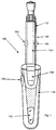
- a suitable curling iron is in Fig. 1 pictured. It has a handle part 110, which is equipped with a viewing window 112. This viewing window 112 serves to make the fill level of a gas cartridge visible.
- the present invention can thus also be used with devices that are not powered by electricity, namely, for example, gas-powered devices that generate heating power, for example, by catalytic gas combustion.
- the device has a switch 120, which serves as an on / off switch. In principle, it is also conceivable that the switch allows the selection of more than a predetermined starting temperature.
- the device also has a hair treatment unit, which comprises a cylinder rod 132 and a clip 134.
- the clamp 134 can be released from the cylinder rod 132 and hair to be curled is inserted between the cylinder rod 132 and the clamp 134.
- the attachment of at least two sensors at different locations on the curling iron 100 can be considered. It is particularly advantageous to use the area 140 for attaching a first sensor and additionally the area 142 for attaching a second sensor. The sensors are then to the left and right of clip 134. As a result, they are in contact with hair that is being fed to the curling iron and also with hair that is just leaving the area of the curling iron.
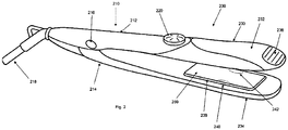
- Fig. 2 shows a hair straightener, which is another hair treatment device according to the invention.
- the hair straightener 200 has a handle area 210 and a hair treatment area 230.
- the handle area comprises a first handle area 212 and a second handle area 214, which are each assigned to the arms of the hair straightener 200.
- the two arms are connected by a connecting joint 216.
- a cable 218 is provided at the end of the hair straightener 200. It is therefore an electrically operated hair treatment device.
- a temperature controller 220 is also provided. In the form of the rotary wheel shown, it is easy to preselect a desired starting temperature.
- the temperature controller 220 can also serve as a switch.
- the device can be switched on or off, for example, by connecting the cable 218 to the mains and by removing the cable from the mains.
- the hair treatment section 230 comprises the hair treatment section of the first arm 232 and the hair treatment section of the second arm 234.
- a grip region 236 can be seen on the first arm 232.
- a similar grip area can also be provided opposite at the hair treatment end of the second arm 234.
- a heating part 238 is visible in the hair treatment area 234 of the second arm 234.
- a corresponding heating part can also be provided in the hair treatment area of the first arm 232.
- an unheated pressure plate can be provided there.
- the heating part 238 is equipped with two or more sensors, a sensor in the area 240 and a further sensor in the area 242. The sensors then measure the temperature of hair which first passes through the area 240 and then through the area 242 in the direction of passage.
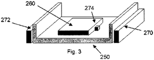
- Fig. 3 shows schematically a cross section through a heating part, as can be used for example as the first heating part 238 in the straightener 200.
- a cross-section can be seen in which the heating surface 250 points downward.
- the heating surface 250 is part of a U-shaped, as a rule metallic heating part.
- a heating element 260 is provided on the rear of the heating part, opposite the heating surface 250. This is essentially heated by resistive heating. There is heat from the heating element and the heating surface 250 continue.
- a first sensor 270 is provided on the side of the heating part, namely on the first of the U-shaped legs. With suitable installation of the heating part in a hair straightener, the area 240 of the first sensor would lie here.
- a second sensor 272 is provided on the other side leg of the u-shape.
- the first sensor 270 can measure a temperature value which is characteristic of the hair straightened and the second sensor 272 can one Measure the value that is characteristic of hair exiting the straightener.
- a third sensor 274 is provided here, which is located in the immediate vicinity of the heating element 260. An even more precise temperature profile can be determined with the third sensor. The third sensor can in particular also serve to keep the temperature of the heating element at a certain constant value as long as it is not necessary to change it.
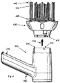
- a hair dryer 300 is drawn in perspective view.
- a handle part 310 This carries the switch 320.
- the switch either serves to bring the air flow to a fixed temperature, but often there are also two or three temperature levels which can be selected with the one switch.
- the warm air outlet nozzle can essentially be regarded as the hair treatment part 330 of the hair dryer 300. This blows out warm air in the outlet direction 332.
- the hair treatment part 330 also carries the connecting element 334, which is designed in the form of a groove-like depression. This connecting element 334 enables the connection to the attachment part 400.
- the attachment part 400 is equipped with a corresponding connecting element 410, which is designed as a nose that can engage in the groove.
- the attachment part 400 has a multiplicity of air outlet elements 420. These are rod-shaped or tubular.
- the air outlet elements 420 bring warm air deep into the hair, especially in the case of a curly hairstyle. Air can also escape at the foot of the air outlet elements through additional nozzles that cannot be seen here. There is typically a distance of a few centimeters between the tips of the air outlet elements and their foot parts.
- First and second sensors can be provided at such a distance.
- the area 440 of a first sensor can be located at the foot of the air outlet elements 420.
- the region 442 of a second sensor can be located at the end of the air outlet elements 420. Sensors attached there are temperature sensors, so that a temperature difference is measured.
- a moisture difference will be measured.
- a characteristic value can in turn be generated with which the temperature of the hair dryer 300 can be regulated.
- the transmission of the characteristic value to the hair treatment device, here the hair dryer, can be done by a cable or wirelessly.
Landscapes
- Physics & Mathematics (AREA)
- Thermal Sciences (AREA)
- Engineering & Computer Science (AREA)
- Multimedia (AREA)
- Cleaning And Drying Hair (AREA)
- Cosmetics (AREA)
Description
- Diese Erfindung betrifft ein Haarbehandlungsgerät und ein korrespondierendes Verfahren zur Haarbehandlung. Als Haarbehandlungsgeräte kommen hier insbesondere Haartrockner, Lockenstäbe und Haarglätter in Betracht. Die Erfindung kann sowohl im privaten Bereich als auch von Friseuren angewandt werden. Insbesondere betrifft die Erfindung eine Temperaturregelung für Haarbehandlungsgeräte und ein zugehöriges Verfahren.
- Die Anmeldung
GB 2 147 204 A (angemeldet von: J.H. Downey - Die Patentanmeldung
GB 2 432 310 A1 - Die Europäische Patentschrift
EP 0 176 003 B1 (Wella AG) offenbart ein Verfahren zur Messung und Regelung des Feuchtigkeitsgehaltes des Haares, welches mit Haartrockenhauben verwendet werden kann. Solche Haartrockenhauben, wie sie wohl typischerweise in Frisiersalons verwendet werden, sollen mit einem Rückluftkanal ausgestattet werden. In diesem Rückluftkanal kann dann ein Luftfeuchtigkeitssensor eingebaut werden. Dieser Sensor wiederum soll ein Signal zum Abschalten des Trocknungsprogramms erzeugen. - Aus der
WO99/26512A1 - Die Europäische Patentanmeldung
EP 1 400 187 A1 (Cho ) offenbart einen Schaltkreis, mit dem die Temperatur eines Glätteisens konstant gehalten werden kann. Dieser exemplarische Schaltkreis ist wie viele andere Schaltkreise dazu bestimmt, Messdaten von einem Temperatursensor aufzunehmen und das Glätteisen auf einer voreingestellten Temperatur möglichst konstant zu halten. Der Temperatursensor wird also nicht zum Variieren der Temperatur benutzt, sondern im Gegenteil vielmehr dazu die einmal eingestellte Temperatur konstant zu halten. - Der Stand der Technik hat also einige Nachteile und Begrenzungen. Insbesondere wird trotz verschiedener Versuche der Temperaturregelung und der Prozeßsteuerung, keine Möglichkeit angeboten, in bequemer Weise die Temperatur automatisch zu steuern.
- Die vorliegende Erfindung macht es sich zur Aufgabe, ein Haarbehandlungsgerät und ein korrespondierendes Verfahren anzubieten, mit dem Haareigenschaften gemessen werden und Temperatursteuerung im Haarbehandlungsgerät genutzt werden.
- Diese Aufgabe wird durch ein Haarbehandlungsgerät nach Anspruch 1 und ein Verfahren zur Haarbehandlung nach Anspruch 8 gelöst.
- Die Erfindung betrifft ein Haarbehandlungsgerät und ein korrespondierendes Verfahren zur Haarbehandlung. Haarbehandlungsgerät, welches geeignet ist, Haare zu erwärmen und welches dazu ein Heizteil aufweist, welches auf eine Anfangstemperatur aufgeheizt wird und dessen Temperatur über eine Temperaturregelung geregelt wird, wobei dem Haarbehandlungsgerät ein erster und ein zweiter Sensor zugeordnet sind, welche Daten messen, wobei die Sensoren Temperaturdaten auslesen, aus denen sich ein Kennwert abhängig von Zustand der Haare erzeugen lässt, wobei der Kennwert die Temperaturregelung beeinflusst, wobei der erste Sensor und der zweite Sensor gegenüberliegend vorgesehen sind, und wobei zwischen dem ersten und dem zweiten Sensor eine Temperaturdifferenz messbar ist und wobei der Kennwert abhängig vom Zustand der Haare die Temperaturdifferenz ist.
- Die vorliegende Erfindung betrifft also allgemein ein Haarbehandlungsgerät. Diese kann ein Haarbehandlungsgerät zur professionellen Verwendung sein, also eines, welches in der Regel in einem Frisiersalon verwendet wird. Das Haarbehandlungsgerät kann ebenfalls eines der üblichen Geräte zur Verwendung im privaten Bereich sein. Dazu gehören insbesondere Haartrockner, Warmluftbürsten, Lockenstäbe und Glätteisen. Diese Geräte weisen alle jeweils mindestens ein Heizteil auf, welches abhängig vom Gerät in verschiedener Form ausgeführt wird. Bei Haartrocknern gibt es in der Regel eine Luftheizung, welche typischerweise aus einer Anordnung beheizter Drähte besteht. Andere Geräte verwenden meist ebenfalls Widerstandsheizungen, beispielsweise in der Form von Heizplatten im Fall eines Glätteisens. In einzelnen Fällen ist auch eine nicht elektrische Heizung vorgesehen, so z.B. bei gasgetriebenen Geräten.
- Beim Einschalten des Gerätes wird dieses Heizteil auf eine Anfangstemperatur aufgeheizt. Im Einzelfall wird das Gerät schon benutzt, bevor diese Temperatur erreicht wird. Die Anfangstemperatur ist aber beim Einschalten des Gerätes vorgegeben. Es kommt beispielsweise ein einfacher Einschaltknopf in Betracht, bei dem eine weitere Temperaturauswahl nicht möglich ist. Neben dem Einschaltknopf kann auch ein Regler vorgesehen sein, mit dem eine Anfangstemperatur ausgewählt werden kann.
- Die Temperatur des Heizteils des Haarbehandlungsgerätes wird nun über einen Temperaturregelung geregelt. Diese Temperaturregelung kann bereits die Anfangstemperatur regeln oder sie wird aktiv, sobald die Anfangstemperatur erreicht wird und dient dazu, den weiteren Temperaturverlauf zu regeln. Das Abschalten des Gerätes ist dabei jedoch nicht Aufgabe der Temperaturregelung. Allerdings kann es alternativ oder zusätzlich, insbesondere bei Glätteisen und Lockenstäben, auch in Betracht kommen, dass die Temperaturregelung das Gerät auch abschalten kann. Dabei kommt die temporäre und die permanente Abschaltung des Heizteils in Betracht.
- Dem Haarbehandlungsgerät ist ein Sensor zugeordnet. Dieser misst Daten, aus denen sich ein Kennwert abhängig vom Zustand der Haare erzeugen lässt. Der Sensor kann beispielsweise in das Haarbehandlungsgerät eingebaut sein. Es kommt alternativ oder zusätzlich aber auch in Frage, dass der Sensor in einem Aufsatzteil zum Haarbehandlungsgerät platziert ist. Ein solches Aufsatzteil wäre beispielsweise eine Aufsteckdüse für einen Haartrockner. Es kommt alternativ oder zusätzlich auch in Frage, dass der Sensor in einem separaten Bauteil zur Verfügung gestellt wird, welches im Wesentlichen nur Messaufgaben übernimmt.
- Dieser Sensor kann verschiedene geeignete Daten messen, aus denen sich ein Kennwert abhängig vom Zustand der Haare erzeugen lässt. Laut der Erfindung sind solche Daten die Haartemperatur. Laut einem alternativen Ausführungsbeispiel, das nicht zur Erfindung gehört, sind solche Daten die Haarfestigkeit oder die Haarfeuchte. Diese Daten können direkt am Haar gemessen werden, sie können aber auch indirekt gemessen werden. Beispielsweise hat die Haartemperatur Einfluß auf die Temperatur eines am Haar anliegenden Bauteils, wie beispielsweise eines Heizteils zum Kontakt mit dem Haar. Laut einem Ausführungsbeispiel, das nicht zur Erfindung gehört, können weitere nützliche Daten auch durch Messung der Zugkraft erzeugt werden, mit denen Haare über mindestens eine Fläche gezogen werden. Die Messung kann mit einer einzelnen Fläche erfolgen oder mit mehreren, insbesondere zwei Flächen. Dabei können die zwei Flächen gegeneinandergepresst werden. Die beiden Heizflächen eines Haarglätters oder die Heiz- und die Klemmfläche eines Lockenstabes kommen dazu in Betracht.
- Aus diesen Daten soll ein Kennwert abhängig vom Zustand der Haare erzeugt werden. Dieses kann ein aus bloß zwei Werten ausgewählter Kennwert sein oder ein aus einer vorgegebenen Anzahl von Werten ausgewählter Kennwert oder auch ein aus einem Kontinuum von Zahlenwerten ausgewählter Kennwert. Erfindungsgemäß soll nun dieser Kennwert die Temperaturregelung beeinflussen. In Betracht kommt als einfache Form der Beeinflussung das Erhöhen oder Absenkung der Temperatur. Es wäre auch möglich, dass der Kennwert die Temperatur entlang einer bestimmten Temperaturkurve variiert.
- Laut der Erfindung liest bei dem Haarbehandlungsgerät der Sensor Temperaturdaten aus. Erfindungsgemäß weist das Haarbehandlungsgerät zwei Sensoren auf. Dabei wird ein Kennwert erzeugt, der eine Temperaturdifferenz ist, welche vom Zustand der Haare abhängig ist. Beispielsweise kann die Behandlungstemperatur erhöht werden, wenn die Temperaturdifferenz groß ist, oder erniedrigt werden, wenn sie klein ist.
- Es hat sich gezeigt, dass der Einsatz von Sensoren und einer erfindungsgemäßen Temperaturregelung besonders vorteilhaft bei Haarglättern oder sogenannten Glätteisen ist. Solche Geräte weisen typischerweise zwei Arme auf, welche auseinander- und zusammengeklappt werden können und zwischen denen das Haar hindurchgeführt wird. Mindestens ein Arm weist in der Regel eine Heizfläche auf, häufig weisen beide Arme je eine Heizfläche auf. Der gegenüberliegende Arm kann eine Anpressfläche aufweisen, mit welcher das Haar auf die Heizfläche gedrückt wird. Die Gestaltung des Haarglätters ist aber häufig auch symmetrisch, d.h. es sind zwei gegenüberliegende Heizflächen vorgesehen, welche für die jeweils andere Heizfläche auch als Anpreßfläche dienen. Haare werden in einer Durchführungsrichtung durch den Haarglätter geführt. Dabei werden sie zunächst an einem vorderen Bereich einer ersten Heizfläche vorbei geführt und dann an einem hinteren Bereich einer Heizfläche, also an einem Bereich, der in Durchführungsrichtung hinter dem vorderen Bereich liegt. Erfindungsgemäß kann nun im vorderen Bereich ein erster Sensor vorgesehen sein und im hinteren Bereich ein zweiter Sensor. Dieser Sensor misst dann an der Heizfläche jeweils eine Temperatur. Dabei kommt es zu Temperaturunterschieden, welche auch von der Art und dem Zustand des durchgeführten Haares abhängen.
- In einem weiteren Aspekt betrifft die vorliegende Erfindung auch ein Verfahren zur thermischen Haarbehandlung, bei dem die Behandlungstemperatur abhängig vom Zustand der Haare automatisch geregelt wird. Ein solches Verfahren kann insbesondere eines sein, bei dem ein Haarglätter als Gerät zur Haarbehandlung eingesetzt wird. Dabei findet der Erstkontakt des Haarbehandlungsgerätes mit dem Haar bei einer voreingestellten Temperatur statt. Diese voreingestellte Temperatur wird dann abhängig von der Temperaturdifferenz, die zwischen erstem und zweitem Sensor gemessen verändert. Insbesondere kommt es in Betracht, dass die voreingestellte Temperatur erhöht wird, wenn zwischen den beiden Sensoren eine große Temperaturdifferenz gemessen wird. Die voreingestellte Temperatur wird dagegen erniedrigt, wenn zwischen den beiden Sensoren eine kleine Temperaturdifferenz gemessen wird.
- Bei den Abbildungen zeigen:
- Fig. 1
- einen Lockenstab in der Aufsicht,
- Fig. 2
- einen Haarglätter in perspektivischer Ansicht,
- Fig. 3
- ein schematisches Schnittbild durch einen Haarglätter,
- Fig. 4
- einen Haartrockner mit Aufsatz.
- Die Erfindung kann mit einem Lockenstab als Haarbehandlungsgerät eingesetzt werden. Ein geeigneter Lockenstab ist in
Fig. 1 abgebildet. Er weist ein Griffteil 110 auf, welches mit einem Sichtfenster 112 ausgestattet ist. Dieses Sichtfenster 112 dient dazu, den Füllstand einer Gaskartusche sichtbar zu machen. Die vorliegende Erfindung kann also auch mit nicht strombetriebenen Geräten verwendet werden, nämlich beispielsweise mit gasgetriebenen, die etwa durch katalytische Gasverbrennung eine Heizleistung erzeugen. Das Gerät weist einen Schalter 120 auf, welcher als Ein-/Ausschalter dient. Es ist im Prinzip auch denkbar, dass der Schalter die Auswahl mehr als einer vorgegebenen Anfangstemperatur erlaubt. Das Gerät weist ferner eine Haarbehandlungseinheit auf, welche einen Zylinderstab 132 und eine Klammer 134 umfasst. Mit Hilfe des Bedienhebels 136 kann die Klammer 134 vom Zylinderstab 132 gelöst werden und zu lockendes Haar wird zwischen Zylinderstab 132 und Klammer 134 eingelegt. Die Anbringung von mindestens zwei Sensoren kommt an verschiedenen Stellen des Lockenstabs 100 in Betracht. Günstig ist insbesondere den Bereich 140 zur Anbringung eines ersten Sensors auszunutzen und zusätzlich den Bereich 142 zur Anbringung eines zweiten Sensors. Die Sensoren liegen dann links und rechts von der Klammer 134. Folglich sind sie in Kontakt mit Haaren, die dem Lockenstab gerade zugeführt werden und ferner mit Haaren, die den Bereich des Lockenstabs gerade verlassen. -
Fig. 2 zeigt einen Haarglätter, welcher ein anderes erfindungsgemäßes Haarbehandlungsgerät darstellt. Der Haarglätter 200 weist einen Griffbereich 210 auf und ein Haarbehandlungsbereich 230. Der Griffbereich umfasst einen ersten Griffbereich 212 und einen zweiten Griffbereich 214, welche jeweils den Armen des Haarglätters 200 zugeordnet sind. Die beiden Arme sind durch ein Verbindungsgelenk 216 verbunden. Am Ende des Haarglätters 200 ist ein Kabel 218 vorgesehen. Es handelt sich also um ein elektrisch betriebenes Haarbehandlungsgerät. Ferner ist ein Temperaturregler 220 vorgesehen. In der abgebildeten Form des Drehrades ist es leicht möglich eine gewünschte Anfangstemperatur vorzuwählen. Der Temperaturregler 220 kann zusätzlich auch als Einschalter dienen. Alternativ kann das Gerät beispielsweise durch Verbindung des Kabels 218 mit dem Netz und durch Abziehen des Kabels vom Stromnetz ein- bzw. ausgeschaltet werden. Der Haarbehandlungsabschnitt 230 umfasst den Haarbehandlungsabschnitt des ersten Arms 232 und den Haarbehandlungsabschnitt des zweiten Arms 234. Am ersten Arm 232 ist ein Griffbereich 236 erkennbar. Ein ähnlicher Griffbereich kann gegenüberliegend auch am Haarbehandlungsende des zweiten Arms 234 vorgesehen werden. Im Haarbehandlungsbereich 234 des zweiten Arms 234 ist ein Heizteil 238 sichtbar. Ein korrespondierendes Heizteil kann im Haarbehandlungsbereich des ersten Arms 232 ebenfalls vorgesehen werden. Alternativ kann dort eine unbeheizte Anpressplatte vorgesehen sein. - Das Heizteil 238 ist mit zwei oder mehr Sensoren ausgestattet, einen Sensor im Bereich 240 und einen weiteren Sensor im Bereich 242. Die Sensoren messen dann die Temperatur von Haaren, welche in Durchführrichtung zunächst den Bereich 240 und dann den Bereich 242 passieren.
-
Fig. 3 zeigt schematisch einen Querschnitt durch ein Heizteil, wie es beispielsweise als erstes Heizteil 238 in dem Haarglätter 200 eingesetzt werden kann. Man sieht einen Schnitt in Querrichtung, bei dem die Heizfläche 250 nach unten weist. Die Heizfläche 250 ist Teil eines u-förmigen in der Regel metallischen Heizteils. Auf der Rückseite des Heizteils, gegenüber der Heizfläche 250, ist ein Heizelement 260 vorgesehen. Dieses wird im Wesentlichen durch resistive Heizung aufgeheizt. Es gibt seine Wärme an das Heizteil und die Heizfläche 250 weiter. Seitlich an dem Heizteil, nämlich am ersten der u-förmigen Schenkel ist ein erster Sensor 270 vorgesehen. Hier läge bei geeignetem Einbau des Heizteils in einen Haarglätter der Bereich 240 des ersten Sensors. Gegenüberliegend, am anderen seitlichen Schenkel der u-Form ist ein zweiter Sensor 272 vorgesehen. Hier läge entsprechend der Bereich 242 des zweiten Sensors. Zusätzliche Sensoren können vorgesehen werden, auch jeweils im Bereich 240 und im Bereich 242. Wenn die Heizfläche 250 im Kontakt mit Haaren steht, kann der erste Sensor 270 einen Temperaturwert messen, der charakteristisch für dem Haarglätter zugeführtes Haar ist und der zweite Sensor 272 kann einen Wert messen, der charakteristisch ist für Haar, das aus dem Haarglätter austritt. Ferner ist hier ein dritter Sensor 274 vorgesehen, der sich in unmittelbarer Nachbarschaft zum Heizelement 260 befindet. Mit dem dritten Sensor kann ein noch genauerer Temperaturverlauf bestimmt werden. Der dritte Sensor kann insbesondere auch dazu dienen, die Temperatur des Heizelementes auf einem bestimmten konstanten Wert zu halten, solange es nicht gilt, diesen zu verändern. - In
Fig. 4 ist in perspektivischer Aufsicht ein Haartrockner 300 gezeichnet. Als ein markantes Element weist er ein Griffteil 310 auf. Dieses trägt den Einschalter 320. Der Einschalter dient entweder dazu, den Luftstrom auf eine feste Temperatur zu bringen, häufig aber gibt es auch zwei oder drei Temperaturstufen, welche mit dem einen Schalter wählbar sind. Als Haarbehandlungsteil 330 des Haartrockners 300 kann im Wesentlich die Warmluftauslassdüse angesehen werden. Diese bläst Warmluft in der Auslassrichtung 332 aus. Das Haarbehandlungsteil 330 trägt auch das Verbindungselement 334, das in der Form einer nutartigen Vertiefung ausgeführt ist. Dieses Verbindungselement 334 ermöglicht die Verbindung mit dem Aufsatzteil 400. Das Aufsatzteil 400 ist mit einem korrespondierenden Verbindungselement 410 ausgestattet, welches als Nase ausgebildet ist, die in die Nut eingreifen kann. Das Aufsatzteil 400 weist eine Vielzahl von Luftaustrittselementen 420 auf. Diese sind stab- oder röhrenförmig ausgeführt. Durch die Luftaustrittselemente 420 wird warme Luft gerade bei einer gelockten Frisur tief ins Haar eingebracht. Luft kann zusätzlich auch am Fuß der Luftaustrittselemente durch zusätzliche, hier nicht erkennbare Düsen austreten. Zwischen den Spitzen der Luftaustrittselemente und ihren Fußteilen liegt ein Abstand von typischerweise einigen Zentimetern. In solchem Abstand können erste und zweite Sensoren vorgesehen werden. Beispielsweise kann am Fuß der Luftaustrittselemente 420 der Bereich 440 eines ersten Sensors liegen. Am Ende der Luftaustrittselemente 420 kann der Bereich 442 eines zweiten Sensors liegen. Dort angebrachte Sensoren sind Temperatursensoren, so dass eine Temperaturdifferenz gemessen wird. Laut einem Ausführungsbeispiel das nicht zur Erfindung gehört, kommt aber ebenfalls in Betracht, dass eine Feuchtigkeitsdifferenz gemessen werden wird. Aufgrund der entsprechenden Messwerte kann wiederum ein Kennwert erzeugt werden, mit dem die Temperatur des Haartrockners 300 reguliert werden kann. Die Übertragung des Kennwertes zum Haarbehandlungsgerät, hier dem Haartrockner, kann etwas durch ein Kabel oder drahtlos erfolgen. - Die Vorsehung zweier Sensoren an den näher beschriebenen Stellen, wie auch andere hierin beschriebene Ausführungsformen der Erfindung, erlauben also einen sehr bequemen, automatisierten und effizienten Haartrocknungsprozess vorzusehen und entsprechende Geräte anzubieten.
-
- 100
- Lockenstab
- 110
- Griffteil
- 112
- Sichtfenster
- 120
- Temperaturregelung
- 130
- Haarbehandlungseinheit
- 132
- Klammer
- 134
- Bedienhebel
- 140
- Bereich des ersten Sensors
- 142
- Bereich des zweiten Sensors
- 200
- Haarglätter
- 210
- Griffteil
- 212
- erster Arm
- 214
- zweiter Arm
- 216
- Verbindungsgelenk
- 218
- Stromkabel
- 220
- Temperaturregler
- 230
- Haarbehandlungseinheit
- 232
- erster Arm
- 234
- zweiter Arm
- 236
- Grifffläche
- 238
- erstes Heizteil
- 240
- Bereich des ersten Sensors
- 242
- Bereich des zweiten Sensors
- 250
- Heizfläche
- 260
- Heizelement
- 270
- erster Sensor
- 272
- zweiter Sensor
- 274
- dritter Sensor
- 300
- Haartrockner
- 310
- Griffteil
- 320
- Einschalter
- 330
- Haarbehandlungsteil
- 332
- Auslassrichtung für Warmluft
- 334
- Verbindungselement
- 400
- Aufsatzteil
- 410
- Verbindungselement
- 420
- Luftaustrittselemente
- 440
- Bereich eines ersten Sensors
- 442
- Bereich eines zweiten Sensors
Claims (11)
- Haarbehandlungsgerät (100;200;300), welches geeignet ist, Haare zu erwärmen und welches dazu ein Heizteil aufweist, welches auf eine Anfangstemperatur aufgeheizt wird und dessen Temperatur über eine Temperaturregelung geregelt wird, wobei dem Haarbehandlungsgerät (100;200;300) ein erster und ein zweiter Sensor zugeordnet sind, welche Daten messen, wobei die Sensoren Temperaturdaten auslesen, aus denen sich ein Kennwert abhängig von Zustand der Haare erzeugen lässt, wobei der Kennwert die Temperaturregelung beeinflusst, wobei der erste Sensor und der zweite Sensor gegenüberliegend vorgesehen sind, und wobei zwischen dem ersten und dem zweiten Sensor eine Temperaturdifferenz messbar ist und wobei der Kennwert abhängig vom Zustand der Haare die Temperaturdifferenz ist.
- Haarbehandlungsgerät (100;200;300) nach Anspruch 1, bei dem der Sensor in das Haarbehandlungsgerät (100;200;300) eingebaut ist.
- Haarbehandlungsgerät (100;200;300) nach Anspruch 1 oder 2, bei dem der Sensor in direktem oder indirektem Kontakt mit dem Haar steht.
- Haarbehandlungsgerät (100;200;300) nach einem der vorherigen Ansprüche, welches ein Haartrockner (300) ist.
- Haarbehandlungsgerät nach einem der vorherigen Ansprüche, welches ein Lockenstab (100) ist.
- Haarbehandlungsgerät nach einem der vorhergehenden Ansprüche, welches ein Haarglätter (200) mit einer Heizfläche (250) zum Kontakt mit den Haaren ist.
- Haarbehandlungsgerät nach Anspruch 6, bei dem der vordere Bereich der Heizfläche (250) einen ersten Sensor (270) aufweist und der in Durchführungsrichtung der Haare hintere Bereich der Heizfläche einen zweiten Sensor (272) aufweist.
- Verfahren zur thermischen Haarbehandlung, mit einem Haarbehandlungsgerät nach einem der vorherigen Ansprüche,wobei der Erstkontakt des Haarbehandlungsgerätes (100;200;300) mit dem Haar bei einer voreingestellten Temperatur stattfindet, wobei die Behandlungstemperatur abhängig vom Zustand der Haare automatisch geregelt wird und wobei die voreingestellte Temperatur abhängig von der Temperaturdifferenz, die zwischen dem ersten und dem zweiten Sensor gemessen wird, verändert wird.
- Verfahren zur Haarbehandlung nach Anspruch 8, bei dem das Haarbehandlungsgerät ein Haarglätter (200) ist.
- Verfahren nach Anspruch 8, bei dem die voreingestellte Temperatur erhöht wird, sofern eine große Temperaturdifferenz zwischen erstem Sensor (270) und zweitem Sensor (272) gemessen wird.
- Verfahren nach Anspruch 8, bei dem die voreingestellte Temperatur erniedrigt wird, sofern eine kleine Temperaturdifferenz zwischen dem ersten Sensor (270) und dem zweiten Sensor (272) gemessen wird.
Priority Applications (7)
| Application Number | Priority Date | Filing Date | Title |
|---|---|---|---|
| ES09009006T ES2795355T3 (es) | 2009-07-10 | 2009-07-10 | Proceso automatizado para el cuidado del cabello |
| EP09009006.9A EP2272391B1 (de) | 2009-07-10 | 2009-07-10 | Automatisierter Haarpflegeprozess |
| RU2011153059/12A RU2541954C2 (ru) | 2009-07-10 | 2010-07-08 | Автоматизированный способ ухода за волосами |
| PCT/IB2010/053131 WO2011004340A2 (en) | 2009-07-10 | 2010-07-08 | Automated hair care process |
| JP2012519110A JP5475127B2 (ja) | 2009-07-10 | 2010-07-08 | 自動ヘアケアプロセス |
| CN201080030949.6A CN102469863B (zh) | 2009-07-10 | 2010-07-08 | 自动毛发护理方法 |
| US13/296,299 US8707969B2 (en) | 2009-07-10 | 2011-11-15 | Automated hair care process |
Applications Claiming Priority (1)
| Application Number | Priority Date | Filing Date | Title |
|---|---|---|---|
| EP09009006.9A EP2272391B1 (de) | 2009-07-10 | 2009-07-10 | Automatisierter Haarpflegeprozess |
Publications (2)
| Publication Number | Publication Date |
|---|---|
| EP2272391A1 EP2272391A1 (de) | 2011-01-12 |
| EP2272391B1 true EP2272391B1 (de) | 2020-04-29 |
Family
ID=41564886
Family Applications (1)
| Application Number | Title | Priority Date | Filing Date |
|---|---|---|---|
| EP09009006.9A Active EP2272391B1 (de) | 2009-07-10 | 2009-07-10 | Automatisierter Haarpflegeprozess |
Country Status (7)
| Country | Link |
|---|---|
| US (1) | US8707969B2 (de) |
| EP (1) | EP2272391B1 (de) |
| JP (1) | JP5475127B2 (de) |
| CN (1) | CN102469863B (de) |
| ES (1) | ES2795355T3 (de) |
| RU (1) | RU2541954C2 (de) |
| WO (1) | WO2011004340A2 (de) |
Families Citing this family (24)
| Publication number | Priority date | Publication date | Assignee | Title |
|---|---|---|---|---|
| US9138038B2 (en) * | 2011-05-20 | 2015-09-22 | Spectrum Brands, Inc. | Hair styling apparatus having hair-protection function |
| KR20140058494A (ko) * | 2011-06-13 | 2014-05-14 | 쿨웨이 인코포레이티드 | 동적이고 최적인 모발 스타일링 온도 제어를 위한 모발 관리 도구 및 방법 |
| CN104411204A (zh) * | 2012-06-20 | 2015-03-11 | 博朗有限公司 | 带有传感器的个人器具 |
| EP2676567B1 (de) * | 2012-06-20 | 2019-05-15 | Braun GmbH | Persönliches Gerät mit verschiedenen Betriebsmodus |
| US8967159B1 (en) * | 2012-08-17 | 2015-03-03 | Nyrisha Jenkins | Hair styling iron |
| WO2014054489A1 (ja) * | 2012-10-04 | 2014-04-10 | 株式会社 資生堂 | 美容器具 |
| CN102960931B (zh) * | 2012-11-19 | 2015-09-02 | 温州市中芝贸易有限公司 | 干湿自动检测直发器 |
| PL2997109T3 (pl) | 2013-05-14 | 2018-07-31 | Merck Patent Gmbh | Ośrodek ciekłokrystaliczny i urządzenie ciekłokrystaliczne |
| EP3051974B1 (de) | 2013-09-30 | 2018-08-29 | Kenford Industrial Company Ltd | Haarglätteisen |
| DE102014206503A1 (de) * | 2014-04-04 | 2015-10-08 | BSH Hausgeräte GmbH | Haarglätter |
| DE102015204611A1 (de) | 2015-03-13 | 2016-09-15 | BSH Hausgeräte GmbH | Haarbehandlungsgerät, insbesondere Haarglätter oder Lockenstab |
| CN108289538A (zh) * | 2015-11-25 | 2018-07-17 | 皇家飞利浦有限公司 | 头发造型设备 |
| US10405630B2 (en) * | 2016-07-29 | 2019-09-10 | Spur Concepts Inc | Systems and methods for delivering heat in a battery powered blow dryer |
| US11363871B2 (en) * | 2016-09-19 | 2022-06-21 | Diversame, Inc. | Hair styling device |
| USD829989S1 (en) * | 2016-09-21 | 2018-10-02 | Shenzhen Lady Merry Technology Co., Ltd. | Hairdressing apparatus |
| US10470545B2 (en) * | 2017-09-29 | 2019-11-12 | L'oreal | System including a brush, hair dryer, and client device to assist users to achieve the best drying and styling performance |
| WO2019067716A1 (en) * | 2017-09-29 | 2019-04-04 | L'oreal | SYSTEM COMPRISING A BRUSH, A HAIR DRYER AND A CLIENT DEVICE TO HELP USERS PERFORM THE BEST DRYING AND STYLING PERFORMANCE |
| EP3524086A1 (de) | 2018-02-09 | 2019-08-14 | Koninklijke Philips N.V. | Haarglätter |
| EP3598919A1 (de) | 2018-07-25 | 2020-01-29 | Koninklijke Philips N.V. | Fönaufsatz |
| CN210144047U (zh) * | 2018-12-10 | 2020-03-17 | 飞利浦(中国)投资有限公司 | 直发器 |
| JP7199025B2 (ja) * | 2019-04-09 | 2023-01-05 | パナソニックIpマネジメント株式会社 | 加熱送風システム |
| JP7555034B2 (ja) * | 2020-02-21 | 2024-09-24 | パナソニックIpマネジメント株式会社 | ヘアケア装置 |
| KR20230051680A (ko) * | 2020-09-09 | 2023-04-18 | 드림 이노베이션 테크놀로지 (쑤저우) 컴퍼니 리미티드 | 온도 제어 파라미터 교정 방법 |
| GB2612788B (en) * | 2021-11-10 | 2024-11-13 | Dyson Technology Ltd | A haircare appliance |
Citations (7)
| Publication number | Priority date | Publication date | Assignee | Title |
|---|---|---|---|---|
| FR1217860A (fr) | 1958-12-11 | 1960-05-06 | Nouveaux perfectionnements aux séchoirs pour cheveux | |
| FR1283905A (fr) | 1960-12-26 | 1962-02-09 | Séchoir pour cheveux | |
| US3082540A (en) | 1956-07-26 | 1963-03-26 | Ventilation Et D Electricite A | Hair drier |
| DE1272495B (de) | 1958-05-20 | 1968-07-11 | Ventilation & D Electricite Ap | Vorrichtung zur UEberwachung des Trocknungsgrades der Haare waehrend der mit einer Trockenhaube durchzufuehrenden Haartrocknung |
| JPH05293010A (ja) | 1992-04-23 | 1993-11-09 | Matsushita Electric Works Ltd | ヘアードライヤ |
| KR200277215Y1 (ko) | 2001-12-28 | 2002-06-03 | 노광철 | 전기 고데기 |
| KR100851395B1 (ko) | 2007-02-07 | 2008-08-08 | 카오스 주식회사 | 온도교정용 신호 입출력 수단을 갖춘 헤어아이론 및헤어아이론의 발열판 온도 교정 방법 |
Family Cites Families (36)
| Publication number | Priority date | Publication date | Assignee | Title |
|---|---|---|---|---|
| US3658071A (en) * | 1970-07-28 | 1972-04-25 | Westinghouse Electric Corp | Hair roller with range temperature indicator |
| JPS5920161Y2 (ja) * | 1977-04-30 | 1984-06-12 | シャープ株式会社 | 加温式パ−マネント装置の温度感知センサ |
| US4167820A (en) * | 1978-01-19 | 1979-09-18 | Indola Cosmetics B.V. | Electric hair dryer |
| JPS6031602Y2 (ja) * | 1978-04-14 | 1985-09-21 | シャープ株式会社 | 加温式パ−マネント装置 |
| US4424437A (en) * | 1981-02-24 | 1984-01-03 | Clairol Incorporated | Hair dryer with remote sensing temperature control |
| DE3112384A1 (de) * | 1981-03-28 | 1982-11-11 | Müholos-Werk Alfred Müller, 7532 Niefern-Öschelbronn | Haartrockenhaube |
| DE3133851A1 (de) * | 1981-08-27 | 1983-03-24 | Wella Ag | Waermebehandlungsgeraet fuer kopfhaare |
| CA1232177A (en) | 1983-09-19 | 1988-02-02 | John H. Downey | Moisture sensing hair grooming device |
| US4877042A (en) * | 1983-09-19 | 1989-10-31 | Downey John H | Dynamic hair grooming appliance |
| DE3482024D1 (de) * | 1983-12-16 | 1990-05-31 | Takara Co Ltd | Haarbehandlungsapparat. |
| DE3433246A1 (de) | 1984-09-11 | 1986-03-13 | Wella Ag, 6100 Darmstadt | Haartrockenhaube und verfahren zur messung und regelung des feuchtigkeitsgehalts des haares |
| US4602143A (en) * | 1984-11-14 | 1986-07-22 | Clairol Incorporated | Infrared hair styling device |
| DE58908183D1 (de) * | 1988-12-06 | 1994-09-15 | Olymp Karl Herzog Gmbh & Co | Kopftrockenhaube. |
| KR970010953B1 (ko) * | 1989-06-07 | 1997-07-05 | 피브리스 케라틴 피티와이. 리미티드 | 모발세팅기구 |
| DE4306429A1 (de) * | 1993-03-02 | 1994-09-29 | Wella Ag | Verfahren zum Behandeln eines Objekts mit einem Warmluftstrom und Handgerät zur Durchführung des Verfahrens |
| ES2141884T3 (es) * | 1994-03-16 | 2000-04-01 | Koninkl Philips Electronics Nv | Aparato de calentamiento por circulacion de aire, provisto de un dispositivo infrarrojo de gobierno. |
| EP0679350B1 (de) * | 1994-04-27 | 2002-08-07 | Koninklijke Philips Electronics N.V. | Haartrockner mit geregeltem Luftstrom |
| BR9606637A (pt) * | 1995-09-13 | 1997-09-16 | Philips Electronics Nv | Utensílio para tratamento dos cabelos(com medição da umidade do cabelo medindo a resistência do cabelo) e circuito para converter o valor de resistência de um resistor em um sinal de medição |
| US5785064A (en) * | 1997-03-07 | 1998-07-28 | Simpson; Timothy A. | High temperature externally heated hair-styling devices |
| WO1999026512A1 (en) * | 1997-11-21 | 1999-06-03 | Koninklijke Philips Electronics N.V. | Method of and hair dryer for drying hair using remote sensing of the moisture content of the hair |
| JP2000232911A (ja) * | 1999-02-15 | 2000-08-29 | Milbon Co Ltd | ヘアーアイロン |
| US6449870B1 (en) * | 2000-09-15 | 2002-09-17 | Louis Perez | Portable hair dryer |
| JP4672219B2 (ja) * | 2001-09-11 | 2011-04-20 | ウチヤ・サーモスタット株式会社 | 安全装置 |
| KR200306878Y1 (ko) | 2002-09-18 | 2003-03-10 | 조옥남 | 헤어아이롱 온도제어회로 |
| US6964116B2 (en) * | 2002-12-02 | 2005-11-15 | Kroll Mollie B | Ambulatory hairdryer |
| US7586066B2 (en) * | 2004-11-22 | 2009-09-08 | Chris Baldwin Bell | Hair styling device and method |
| GB2469768A (en) * | 2005-11-18 | 2010-10-27 | Jemella Ltd | Electric hair iron with voltage control means |
| US7356943B2 (en) * | 2006-05-17 | 2008-04-15 | Sabeeh Behbehani | Automatic hair dryer |
| JP4359300B2 (ja) * | 2006-09-21 | 2009-11-04 | 株式会社東芝 | 温冷感判定装置、温冷感判定方法、温冷感判定プログラム、空調制御装置、空調制御方法および空調制御プログラム |
| KR100696071B1 (ko) * | 2006-12-29 | 2007-03-16 | 심국현 | 퍼머롯드와 이러한 퍼머롯드에 효율적인 전열을 수행하는가열장치 |
| CN201008412Y (zh) * | 2007-02-02 | 2008-01-23 | 曹福福 | 红外感应电吹风机 |
| US8800163B2 (en) * | 2007-08-21 | 2014-08-12 | Heidi Schmid | Hair care appliance and method of using same |
| US7913416B1 (en) * | 2008-05-12 | 2011-03-29 | Frank Scieri | Portable hair dryer optimally having a dual heating source |
| ES2494392T3 (es) * | 2008-09-11 | 2014-09-15 | Syneron Medical Ltd. | Aparato de uso personal de tratamiento cutáneo sin riesgo |
| US8480724B2 (en) * | 2009-05-06 | 2013-07-09 | Deborah C Bly | Assembly and method for treating and preventing moisture related skin dermatitis |
| JP3147636U (ja) * | 2018-09-19 | 2009-01-15 | 株式会社アルバジャパン | ヘアアイロン、及びスタンド |
-
2009
- 2009-07-10 ES ES09009006T patent/ES2795355T3/es active Active
- 2009-07-10 EP EP09009006.9A patent/EP2272391B1/de active Active
-
2010
- 2010-07-08 JP JP2012519110A patent/JP5475127B2/ja not_active Expired - Fee Related
- 2010-07-08 WO PCT/IB2010/053131 patent/WO2011004340A2/en not_active Ceased
- 2010-07-08 CN CN201080030949.6A patent/CN102469863B/zh active Active
- 2010-07-08 RU RU2011153059/12A patent/RU2541954C2/ru not_active IP Right Cessation
-
2011
- 2011-11-15 US US13/296,299 patent/US8707969B2/en not_active Expired - Fee Related
Patent Citations (7)
| Publication number | Priority date | Publication date | Assignee | Title |
|---|---|---|---|---|
| US3082540A (en) | 1956-07-26 | 1963-03-26 | Ventilation Et D Electricite A | Hair drier |
| DE1272495B (de) | 1958-05-20 | 1968-07-11 | Ventilation & D Electricite Ap | Vorrichtung zur UEberwachung des Trocknungsgrades der Haare waehrend der mit einer Trockenhaube durchzufuehrenden Haartrocknung |
| FR1217860A (fr) | 1958-12-11 | 1960-05-06 | Nouveaux perfectionnements aux séchoirs pour cheveux | |
| FR1283905A (fr) | 1960-12-26 | 1962-02-09 | Séchoir pour cheveux | |
| JPH05293010A (ja) | 1992-04-23 | 1993-11-09 | Matsushita Electric Works Ltd | ヘアードライヤ |
| KR200277215Y1 (ko) | 2001-12-28 | 2002-06-03 | 노광철 | 전기 고데기 |
| KR100851395B1 (ko) | 2007-02-07 | 2008-08-08 | 카오스 주식회사 | 온도교정용 신호 입출력 수단을 갖춘 헤어아이론 및헤어아이론의 발열판 온도 교정 방법 |
Also Published As
| Publication number | Publication date |
|---|---|
| JP5475127B2 (ja) | 2014-04-16 |
| EP2272391A1 (de) | 2011-01-12 |
| WO2011004340A3 (en) | 2011-05-05 |
| CN102469863A (zh) | 2012-05-23 |
| CN102469863B (zh) | 2016-11-02 |
| WO2011004340A2 (en) | 2011-01-13 |
| JP2012531997A (ja) | 2012-12-13 |
| RU2541954C2 (ru) | 2015-02-20 |
| ES2795355T3 (es) | 2020-11-23 |
| US20120055501A1 (en) | 2012-03-08 |
| US8707969B2 (en) | 2014-04-29 |
| RU2011153059A (ru) | 2013-08-20 |
Similar Documents
| Publication | Publication Date | Title |
|---|---|---|
| EP2272391A1 (de) | Automatisierter Haarpflegeprozess | |
| DE4236036C2 (de) | Luftdurchströmbares Gerät zur Haartrocknung oder Haarformung | |
| EP2305061B1 (de) | Haarglättvorrichtung | |
| EP2198735B1 (de) | Haarformgerät | |
| DE112013004159B4 (de) | Richtdüsenaufsatz | |
| DE60119394T2 (de) | Vorrichtung zum ausrichten und gestalten vom haaren | |
| DE60316304T2 (de) | Kämmvorrichtung mit einstellbarem zinkenabstand | |
| EP2520189B1 (de) | Haarformvorrichtung | |
| DE69910057T2 (de) | Zubehör zum glätten von haaren | |
| DE102012210275A1 (de) | Haartrockner | |
| EP2591699A1 (de) | Haarpflege- oder -stylinggerät sowie Verfahren zum Betreiben eines solchen Gerätes | |
| DE202018005792U1 (de) | Haarformgerät mit Geschwindigkeitserkennung | |
| EP2245953A1 (de) | Haarformgerät | |
| DE102019008001A1 (de) | Haarstylinggerät | |
| EP2520190B1 (de) | Haarformvorrichtung | |
| DE202013103279U1 (de) | Haarformgerät | |
| DE20119863U1 (de) | Haarformer sowie Haarformaufsatz | |
| DE2615267A1 (de) | Brennschere zur haarbehandlung | |
| EP2397045A1 (de) | Haarglätter | |
| EP2624719B1 (de) | Lockenstab | |
| DE102019008000A1 (de) | Haarstylinggerät | |
| DE202014010130U1 (de) | Vorrichtung zum Erzeugen von Locken | |
| DE2830535C2 (de) | ||
| DE202012001377U1 (de) | Elektrisch beheizte Haarglättungsvorrichtung | |
| DE102014100121A1 (de) | Haarformgerät |
Legal Events
| Date | Code | Title | Description |
|---|---|---|---|
| PUAI | Public reference made under article 153(3) epc to a published international application that has entered the european phase |
Free format text: ORIGINAL CODE: 0009012 |
|
| AK | Designated contracting states |
Kind code of ref document: A1 Designated state(s): AT BE BG CH CY CZ DE DK EE ES FI FR GB GR HR HU IE IS IT LI LT LU LV MC MK MT NL NO PL PT RO SE SI SK SM TR |
|
| AX | Request for extension of the european patent |
Extension state: AL BA RS |
|
| 17P | Request for examination filed |
Effective date: 20110311 |
|
| 17Q | First examination report despatched |
Effective date: 20110412 |
|
| STAA | Information on the status of an ep patent application or granted ep patent |
Free format text: STATUS: EXAMINATION IS IN PROGRESS |
|
| GRAP | Despatch of communication of intention to grant a patent |
Free format text: ORIGINAL CODE: EPIDOSNIGR1 |
|
| STAA | Information on the status of an ep patent application or granted ep patent |
Free format text: STATUS: GRANT OF PATENT IS INTENDED |
|
| INTG | Intention to grant announced |
Effective date: 20191204 |
|
| GRAS | Grant fee paid |
Free format text: ORIGINAL CODE: EPIDOSNIGR3 |
|
| GRAA | (expected) grant |
Free format text: ORIGINAL CODE: 0009210 |
|
| STAA | Information on the status of an ep patent application or granted ep patent |
Free format text: STATUS: THE PATENT HAS BEEN GRANTED |
|
| AK | Designated contracting states |
Kind code of ref document: B1 Designated state(s): AT BE BG CH CY CZ DE DK EE ES FI FR GB GR HR HU IE IS IT LI LT LU LV MC MK MT NL NO PL PT RO SE SI SK SM TR |
|
| REG | Reference to a national code |
Ref country code: GB Ref legal event code: FG4D Free format text: NOT ENGLISH |
|
| REG | Reference to a national code |
Ref country code: CH Ref legal event code: EP |
|
| REG | Reference to a national code |
Ref country code: DE Ref legal event code: R096 Ref document number: 502009016178 Country of ref document: DE |
|
| REG | Reference to a national code |
Ref country code: AT Ref legal event code: REF Ref document number: 1262013 Country of ref document: AT Kind code of ref document: T Effective date: 20200515 |
|
| REG | Reference to a national code |
Ref country code: IE Ref legal event code: FG4D Free format text: LANGUAGE OF EP DOCUMENT: GERMAN |
|
| REG | Reference to a national code |
Ref country code: NL Ref legal event code: FP |
|
| REG | Reference to a national code |
Ref country code: LT Ref legal event code: MG4D |
|
| PG25 | Lapsed in a contracting state [announced via postgrant information from national office to epo] |
Ref country code: GR Free format text: LAPSE BECAUSE OF FAILURE TO SUBMIT A TRANSLATION OF THE DESCRIPTION OR TO PAY THE FEE WITHIN THE PRESCRIBED TIME-LIMIT Effective date: 20200730 Ref country code: PT Free format text: LAPSE BECAUSE OF FAILURE TO SUBMIT A TRANSLATION OF THE DESCRIPTION OR TO PAY THE FEE WITHIN THE PRESCRIBED TIME-LIMIT Effective date: 20200831 Ref country code: NO Free format text: LAPSE BECAUSE OF FAILURE TO SUBMIT A TRANSLATION OF THE DESCRIPTION OR TO PAY THE FEE WITHIN THE PRESCRIBED TIME-LIMIT Effective date: 20200729 Ref country code: IS Free format text: LAPSE BECAUSE OF FAILURE TO SUBMIT A TRANSLATION OF THE DESCRIPTION OR TO PAY THE FEE WITHIN THE PRESCRIBED TIME-LIMIT Effective date: 20200829 Ref country code: SE Free format text: LAPSE BECAUSE OF FAILURE TO SUBMIT A TRANSLATION OF THE DESCRIPTION OR TO PAY THE FEE WITHIN THE PRESCRIBED TIME-LIMIT Effective date: 20200429 Ref country code: FI Free format text: LAPSE BECAUSE OF FAILURE TO SUBMIT A TRANSLATION OF THE DESCRIPTION OR TO PAY THE FEE WITHIN THE PRESCRIBED TIME-LIMIT Effective date: 20200429 Ref country code: LT Free format text: LAPSE BECAUSE OF FAILURE TO SUBMIT A TRANSLATION OF THE DESCRIPTION OR TO PAY THE FEE WITHIN THE PRESCRIBED TIME-LIMIT Effective date: 20200429 |
|
| REG | Reference to a national code |
Ref country code: ES Ref legal event code: FG2A Ref document number: 2795355 Country of ref document: ES Kind code of ref document: T3 Effective date: 20201123 |
|
| PG25 | Lapsed in a contracting state [announced via postgrant information from national office to epo] |
Ref country code: BG Free format text: LAPSE BECAUSE OF FAILURE TO SUBMIT A TRANSLATION OF THE DESCRIPTION OR TO PAY THE FEE WITHIN THE PRESCRIBED TIME-LIMIT Effective date: 20200729 Ref country code: HR Free format text: LAPSE BECAUSE OF FAILURE TO SUBMIT A TRANSLATION OF THE DESCRIPTION OR TO PAY THE FEE WITHIN THE PRESCRIBED TIME-LIMIT Effective date: 20200429 Ref country code: LV Free format text: LAPSE BECAUSE OF FAILURE TO SUBMIT A TRANSLATION OF THE DESCRIPTION OR TO PAY THE FEE WITHIN THE PRESCRIBED TIME-LIMIT Effective date: 20200429 |
|
| REG | Reference to a national code |
Ref country code: DE Ref legal event code: R026 Ref document number: 502009016178 Country of ref document: DE |
|
| PG25 | Lapsed in a contracting state [announced via postgrant information from national office to epo] |
Ref country code: RO Free format text: LAPSE BECAUSE OF FAILURE TO SUBMIT A TRANSLATION OF THE DESCRIPTION OR TO PAY THE FEE WITHIN THE PRESCRIBED TIME-LIMIT Effective date: 20200429 Ref country code: IT Free format text: LAPSE BECAUSE OF FAILURE TO SUBMIT A TRANSLATION OF THE DESCRIPTION OR TO PAY THE FEE WITHIN THE PRESCRIBED TIME-LIMIT Effective date: 20200429 Ref country code: DK Free format text: LAPSE BECAUSE OF FAILURE TO SUBMIT A TRANSLATION OF THE DESCRIPTION OR TO PAY THE FEE WITHIN THE PRESCRIBED TIME-LIMIT Effective date: 20200429 Ref country code: EE Free format text: LAPSE BECAUSE OF FAILURE TO SUBMIT A TRANSLATION OF THE DESCRIPTION OR TO PAY THE FEE WITHIN THE PRESCRIBED TIME-LIMIT Effective date: 20200429 Ref country code: SM Free format text: LAPSE BECAUSE OF FAILURE TO SUBMIT A TRANSLATION OF THE DESCRIPTION OR TO PAY THE FEE WITHIN THE PRESCRIBED TIME-LIMIT Effective date: 20200429 Ref country code: CZ Free format text: LAPSE BECAUSE OF FAILURE TO SUBMIT A TRANSLATION OF THE DESCRIPTION OR TO PAY THE FEE WITHIN THE PRESCRIBED TIME-LIMIT Effective date: 20200429 |
|
| PLBI | Opposition filed |
Free format text: ORIGINAL CODE: 0009260 |
|
| PLAB | Opposition data, opponent's data or that of the opponent's representative modified |
Free format text: ORIGINAL CODE: 0009299OPPO |
|
| PLAX | Notice of opposition and request to file observation + time limit sent |
Free format text: ORIGINAL CODE: EPIDOSNOBS2 |
|
| PG25 | Lapsed in a contracting state [announced via postgrant information from national office to epo] |
Ref country code: SK Free format text: LAPSE BECAUSE OF FAILURE TO SUBMIT A TRANSLATION OF THE DESCRIPTION OR TO PAY THE FEE WITHIN THE PRESCRIBED TIME-LIMIT Effective date: 20200429 Ref country code: MC Free format text: LAPSE BECAUSE OF FAILURE TO SUBMIT A TRANSLATION OF THE DESCRIPTION OR TO PAY THE FEE WITHIN THE PRESCRIBED TIME-LIMIT Effective date: 20200429 Ref country code: PL Free format text: LAPSE BECAUSE OF FAILURE TO SUBMIT A TRANSLATION OF THE DESCRIPTION OR TO PAY THE FEE WITHIN THE PRESCRIBED TIME-LIMIT Effective date: 20200429 |
|
| REG | Reference to a national code |
Ref country code: CH Ref legal event code: PL |
|
| 26 | Opposition filed |
Opponent name: BABYLISS FACO S.P.R.L. Effective date: 20210128 |
|
| R26 | Opposition filed (corrected) |
Opponent name: BABYLISS FACO S.P.R.L. Effective date: 20210128 |
|
| REG | Reference to a national code |
Ref country code: BE Ref legal event code: MM Effective date: 20200731 |
|
| PG25 | Lapsed in a contracting state [announced via postgrant information from national office to epo] |
Ref country code: CH Free format text: LAPSE BECAUSE OF NON-PAYMENT OF DUE FEES Effective date: 20200731 Ref country code: LI Free format text: LAPSE BECAUSE OF NON-PAYMENT OF DUE FEES Effective date: 20200731 Ref country code: LU Free format text: LAPSE BECAUSE OF NON-PAYMENT OF DUE FEES Effective date: 20200710 |
|
| PLAB | Opposition data, opponent's data or that of the opponent's representative modified |
Free format text: ORIGINAL CODE: 0009299OPPO |
|
| PG25 | Lapsed in a contracting state [announced via postgrant information from national office to epo] |
Ref country code: BE Free format text: LAPSE BECAUSE OF NON-PAYMENT OF DUE FEES Effective date: 20200731 Ref country code: SI Free format text: LAPSE BECAUSE OF FAILURE TO SUBMIT A TRANSLATION OF THE DESCRIPTION OR TO PAY THE FEE WITHIN THE PRESCRIBED TIME-LIMIT Effective date: 20200429 |
|
| R26 | Opposition filed (corrected) |
Opponent name: BABYLISS FACO S.P.R.L. Effective date: 20210128 |
|
| PLBB | Reply of patent proprietor to notice(s) of opposition received |
Free format text: ORIGINAL CODE: EPIDOSNOBS3 |
|
| PG25 | Lapsed in a contracting state [announced via postgrant information from national office to epo] |
Ref country code: IE Free format text: LAPSE BECAUSE OF NON-PAYMENT OF DUE FEES Effective date: 20200710 |
|
| REG | Reference to a national code |
Ref country code: AT Ref legal event code: MM01 Ref document number: 1262013 Country of ref document: AT Kind code of ref document: T Effective date: 20200710 |
|
| PG25 | Lapsed in a contracting state [announced via postgrant information from national office to epo] |
Ref country code: AT Free format text: LAPSE BECAUSE OF NON-PAYMENT OF DUE FEES Effective date: 20200710 |
|
| PLBP | Opposition withdrawn |
Free format text: ORIGINAL CODE: 0009264 |
|
| PLBD | Termination of opposition procedure: decision despatched |
Free format text: ORIGINAL CODE: EPIDOSNOPC1 |
|
| REG | Reference to a national code |
Ref country code: DE Ref legal event code: R100 Ref document number: 502009016178 Country of ref document: DE |
|
| PG25 | Lapsed in a contracting state [announced via postgrant information from national office to epo] |
Ref country code: TR Free format text: LAPSE BECAUSE OF FAILURE TO SUBMIT A TRANSLATION OF THE DESCRIPTION OR TO PAY THE FEE WITHIN THE PRESCRIBED TIME-LIMIT Effective date: 20200429 Ref country code: MT Free format text: LAPSE BECAUSE OF FAILURE TO SUBMIT A TRANSLATION OF THE DESCRIPTION OR TO PAY THE FEE WITHIN THE PRESCRIBED TIME-LIMIT Effective date: 20200429 Ref country code: CY Free format text: LAPSE BECAUSE OF FAILURE TO SUBMIT A TRANSLATION OF THE DESCRIPTION OR TO PAY THE FEE WITHIN THE PRESCRIBED TIME-LIMIT Effective date: 20200429 |
|
| PG25 | Lapsed in a contracting state [announced via postgrant information from national office to epo] |
Ref country code: MK Free format text: LAPSE BECAUSE OF FAILURE TO SUBMIT A TRANSLATION OF THE DESCRIPTION OR TO PAY THE FEE WITHIN THE PRESCRIBED TIME-LIMIT Effective date: 20200429 |
|
| PLBM | Termination of opposition procedure: date of legal effect published |
Free format text: ORIGINAL CODE: 0009276 |
|
| 27C | Opposition proceedings terminated |
Effective date: 20220523 |
|
| P01 | Opt-out of the competence of the unified patent court (upc) registered |
Effective date: 20230430 |
|
| PGFP | Annual fee paid to national office [announced via postgrant information from national office to epo] |
Ref country code: GB Payment date: 20250529 Year of fee payment: 17 |
|
| PGFP | Annual fee paid to national office [announced via postgrant information from national office to epo] |
Ref country code: NL Payment date: 20250613 Year of fee payment: 17 |
|
| PGFP | Annual fee paid to national office [announced via postgrant information from national office to epo] |
Ref country code: FR Payment date: 20250610 Year of fee payment: 17 |
|
| PGFP | Annual fee paid to national office [announced via postgrant information from national office to epo] |
Ref country code: ES Payment date: 20250806 Year of fee payment: 17 |
|
| PGFP | Annual fee paid to national office [announced via postgrant information from national office to epo] |
Ref country code: DE Payment date: 20250604 Year of fee payment: 17 |