EP2263302B1 - Steuereinheit für einen gleichstrom-wechselstrom-wandler einer resonanten stromwandlungsschaltung, insbesondere für einen gleichstrom-wechselstrom-wandler zur verwendung in einem hochspannungsgeneratorschaltkreis einer modernen computertomographievorrichtung oder eines röntgensystems - Google Patents
Steuereinheit für einen gleichstrom-wechselstrom-wandler einer resonanten stromwandlungsschaltung, insbesondere für einen gleichstrom-wechselstrom-wandler zur verwendung in einem hochspannungsgeneratorschaltkreis einer modernen computertomographievorrichtung oder eines röntgensystems Download PDFInfo
- Publication number
- EP2263302B1 EP2263302B1 EP09717168A EP09717168A EP2263302B1 EP 2263302 B1 EP2263302 B1 EP 2263302B1 EP 09717168 A EP09717168 A EP 09717168A EP 09717168 A EP09717168 A EP 09717168A EP 2263302 B1 EP2263302 B1 EP 2263302B1
- Authority
- EP
- European Patent Office
- Prior art keywords
- resonant
- power
- transformer
- power inverter
- winding
- Prior art date
- Legal status (The legal status is an assumption and is not a legal conclusion. Google has not performed a legal analysis and makes no representation as to the accuracy of the status listed.)
- Not-in-force
Links
- 238000002591 computed tomography Methods 0.000 title claims abstract description 19
- 238000004804 winding Methods 0.000 claims abstract description 84
- 230000016507 interphase Effects 0.000 claims abstract description 53
- 238000000034 method Methods 0.000 claims abstract description 22
- 238000003384 imaging method Methods 0.000 claims abstract description 21
- 238000002583 angiography Methods 0.000 claims abstract description 16
- 229920006395 saturated elastomer Polymers 0.000 claims abstract description 11
- 230000001419 dependent effect Effects 0.000 claims description 8
- 238000004590 computer program Methods 0.000 claims description 3
- 239000003990 capacitor Substances 0.000 description 6
- 238000009499 grossing Methods 0.000 description 5
- 238000001514 detection method Methods 0.000 description 4
- 230000000694 effects Effects 0.000 description 4
- 238000001914 filtration Methods 0.000 description 4
- 238000010586 diagram Methods 0.000 description 3
- XUIMIQQOPSSXEZ-UHFFFAOYSA-N Silicon Chemical compound [Si] XUIMIQQOPSSXEZ-UHFFFAOYSA-N 0.000 description 2
- 230000008901 benefit Effects 0.000 description 2
- 230000008878 coupling Effects 0.000 description 2
- 238000010168 coupling process Methods 0.000 description 2
- 238000005859 coupling reaction Methods 0.000 description 2
- 238000005516 engineering process Methods 0.000 description 2
- 230000001939 inductive effect Effects 0.000 description 2
- 230000004044 response Effects 0.000 description 2
- 229910052710 silicon Inorganic materials 0.000 description 2
- 239000010703 silicon Substances 0.000 description 2
- 230000001052 transient effect Effects 0.000 description 2
- 230000015556 catabolic process Effects 0.000 description 1
- 238000006243 chemical reaction Methods 0.000 description 1
- 230000004907 flux Effects 0.000 description 1
- 230000000977 initiatory effect Effects 0.000 description 1
- 230000003071 parasitic effect Effects 0.000 description 1
- 230000000737 periodic effect Effects 0.000 description 1
- 230000009467 reduction Effects 0.000 description 1
- 230000000630 rising effect Effects 0.000 description 1
- 238000005070 sampling Methods 0.000 description 1
- 230000009466 transformation Effects 0.000 description 1
Images


Classifications
-
- H—ELECTRICITY
- H02—GENERATION; CONVERSION OR DISTRIBUTION OF ELECTRIC POWER
- H02M—APPARATUS FOR CONVERSION BETWEEN AC AND AC, BETWEEN AC AND DC, OR BETWEEN DC AND DC, AND FOR USE WITH MAINS OR SIMILAR POWER SUPPLY SYSTEMS; CONVERSION OF DC OR AC INPUT POWER INTO SURGE OUTPUT POWER; CONTROL OR REGULATION THEREOF
- H02M7/00—Conversion of AC power input into DC power output; Conversion of DC power input into AC power output
- H02M7/42—Conversion of DC power input into AC power output without possibility of reversal
- H02M7/44—Conversion of DC power input into AC power output without possibility of reversal by static converters
- H02M7/48—Conversion of DC power input into AC power output without possibility of reversal by static converters using discharge tubes with control electrode or semiconductor devices with control electrode
- H02M7/53—Conversion of DC power input into AC power output without possibility of reversal by static converters using discharge tubes with control electrode or semiconductor devices with control electrode using devices of a triode or transistor type requiring continuous application of a control signal
- H02M7/537—Conversion of DC power input into AC power output without possibility of reversal by static converters using discharge tubes with control electrode or semiconductor devices with control electrode using devices of a triode or transistor type requiring continuous application of a control signal using semiconductor devices only, e.g. single switched pulse inverters
- H02M7/5387—Conversion of DC power input into AC power output without possibility of reversal by static converters using discharge tubes with control electrode or semiconductor devices with control electrode using devices of a triode or transistor type requiring continuous application of a control signal using semiconductor devices only, e.g. single switched pulse inverters in a bridge configuration
- H02M7/53871—Conversion of DC power input into AC power output without possibility of reversal by static converters using discharge tubes with control electrode or semiconductor devices with control electrode using devices of a triode or transistor type requiring continuous application of a control signal using semiconductor devices only, e.g. single switched pulse inverters in a bridge configuration with automatic control of output voltage or current
- H02M7/53873—Conversion of DC power input into AC power output without possibility of reversal by static converters using discharge tubes with control electrode or semiconductor devices with control electrode using devices of a triode or transistor type requiring continuous application of a control signal using semiconductor devices only, e.g. single switched pulse inverters in a bridge configuration with automatic control of output voltage or current with digital control
-
- H—ELECTRICITY
- H02—GENERATION; CONVERSION OR DISTRIBUTION OF ELECTRIC POWER
- H02M—APPARATUS FOR CONVERSION BETWEEN AC AND AC, BETWEEN AC AND DC, OR BETWEEN DC AND DC, AND FOR USE WITH MAINS OR SIMILAR POWER SUPPLY SYSTEMS; CONVERSION OF DC OR AC INPUT POWER INTO SURGE OUTPUT POWER; CONTROL OR REGULATION THEREOF
- H02M1/00—Details of apparatus for conversion
- H02M1/40—Means for preventing magnetic saturation
-
- H—ELECTRICITY
- H02—GENERATION; CONVERSION OR DISTRIBUTION OF ELECTRIC POWER
- H02M—APPARATUS FOR CONVERSION BETWEEN AC AND AC, BETWEEN AC AND DC, OR BETWEEN DC AND DC, AND FOR USE WITH MAINS OR SIMILAR POWER SUPPLY SYSTEMS; CONVERSION OF DC OR AC INPUT POWER INTO SURGE OUTPUT POWER; CONTROL OR REGULATION THEREOF
- H02M1/00—Details of apparatus for conversion
- H02M1/0064—Magnetic structures combining different functions, e.g. storage, filtering or transformation
-
- Y—GENERAL TAGGING OF NEW TECHNOLOGICAL DEVELOPMENTS; GENERAL TAGGING OF CROSS-SECTIONAL TECHNOLOGIES SPANNING OVER SEVERAL SECTIONS OF THE IPC; TECHNICAL SUBJECTS COVERED BY FORMER USPC CROSS-REFERENCE ART COLLECTIONS [XRACs] AND DIGESTS
- Y02—TECHNOLOGIES OR APPLICATIONS FOR MITIGATION OR ADAPTATION AGAINST CLIMATE CHANGE
- Y02B—CLIMATE CHANGE MITIGATION TECHNOLOGIES RELATED TO BUILDINGS, e.g. HOUSING, HOUSE APPLIANCES OR RELATED END-USER APPLICATIONS
- Y02B70/00—Technologies for an efficient end-user side electric power management and consumption
- Y02B70/10—Technologies improving the efficiency by using switched-mode power supplies [SMPS], i.e. efficient power electronics conversion e.g. power factor correction or reduction of losses in power supplies or efficient standby modes
Definitions
- the present invention refers to a DC/AC power inverter control unit of a resonant-type power converter circuit, in particular a DC/DC converter, for supplying an output power for use in, for example, a high-voltage generator circuitry of an X-ray radiographic imaging system, 3D rotational angiography device or X-ray computed tomography device of the fan- or cone-beam type.
- the present invention is directed to a resonant-type power converter circuit which comprises an interphase transformer connected in series to at least one series resonant tank circuit at the output of two DC/AC power inverter stages supplying a multi-primary winding high-voltage transformer, wherein said interphase transformer serves for removing the difference in the resonant output currents of the DC/AC power inverter stages.
- the present invention is dedicated to a control method which assures that the interphase transformer is not saturated. This control method ensures zero current operation and provides for that input power losses can be minimized.
- High-voltage generators for X-ray tube power supplies as used in medical X-ray imaging typically comprise at least one multi-phase high-voltage transformer which provides the required power for operating the X-ray tube to the tube's cathode and anode.
- an AC voltage adjusting device such as e.g. an autotransformer
- a switching device such as e.g. a silicon-controlled rectifier (SCR) in conjunction with a bridge rectifier, opens and closes the star point of the multi-phase primary to turn on and off high voltage at the X-ray tube.
- SCR silicon-controlled rectifier
- Inductive and capacitive effects in the transformer and associated power supply components generally cause the high voltage to rise above its steady-state level during a period immediately following completion of the circuit.
- the severity of this overshoot is known to increase with increasing X-ray tube voltage and to decrease with increasing X-ray tube current.
- PWM pulse width modulation
- inverter-fed DC/DC power converters with a high-voltage transformer parasitic resonant link as used for an X-ray power generator thereby exhibit stiff nonlinear characteristics due to phase-shifted voltage regulation and diode cutoff operation in a high-voltage rectifier because of the wide load setting ranges in practical applications.
- Modem resonant DC/DC converters such as those used within high-voltage generator circuitries for providing X-ray tubes with high supply voltages, are operated at high switching frequencies. It is evident that any switching losses incurred by the associated power switches in a single switching cycle have to be reduced in order to limit the overall power losses.
- ZCS zero current switching
- high-voltage high-power X-ray generators using voltage-fed high-frequency inverters in conjunction with a high-voltage transformer link have to meet the following requirements: (i) short rising period in start transient of X-ray tube voltage, (ii) no overshoot transient response in tube voltage, and (iii) minimized voltage ripple in periodic steady-state under extremely wide load variations and filament heater current fluctuation conditions of the X-ray tube.
- US 5,559,684 relates to a switching regulator composed of a push-pull converter with a series connected boost regulator.
- Primary windings of the converter transformer are galvanically separated from each other and the output inductance of the boost regulator is divided into two individual inductances, which are respectively supplied to one of the push-pull branches of a push-pull converter.
- Each of the push-pull branches has at least one resonance capacitor which is connected to the series connection of one individual inductance with a primary winding of the push-pull converter transformer.
- the individual inductances are magnetically weakly coupled.
- High-voltage generator circuitries for use in CT or X-ray devices preferably consist of a series resonant circuit for driving a high-voltage transformer.
- Conventional DC/DC power controllers as used in the scope of such a high-voltage generator circuitry such as e.g. described in WO 2006 / 114719 A1 , thereby demand the modulator to switch the DC/AC power inverter stages different from each other, which hence results in different resonant currents in the DC/AC power inverter stages operating together on one multi-winding transformer.
- zero current switching is no longer ensured for all operation points, which leads to an introduction of unwanted losses.
- a first exemplary embodiment of the present invention is dedicated to a DC/AC power inverter control unit of a resonant power converter circuit.
- Said power converter circuit thereby comprises two independent DC/AC power inverter stages for supplying a multi-primary winding transformer with said DC/AC power inverter stages being inductively coupled by a first and a second winding of an interphase transformer which is designed to balance differences in the output currents of the two DC/AC power inverter stages.
- said resonant power converter circuit may be realized as a DC/DC converter for use in a high-voltage generator circuitry and that said multi-primary winding transformer may be designed for high-voltage operation.
- Said high-voltage generator circuitry may serve for supplying an output power for an X-ray radiographic imaging system, 3D rotational angiography device or X-ray computed tomography device of the fan- or cone-beam type.
- Said DC/AC power inverter control unit is adapted to minimize the magnitude of the inverter output currents' difference value to a value which ensures that the interphase transformer is not operated in a saturated state by controlling the switching states and/or switching times of the DC/AC power inverter stages dependent on this current difference, thus enabling zero current operation.
- the first winding of the interphase transformer may preferably be connected in series to at least one resonant tank circuit serially connected to a first primary winding of the multi-winding transformer at the output port of a first one of said DC/AC power inverter stages
- the second winding of the interphase transformer may preferably be connected in series to at least one further resonant tank circuit serially connected to a second primary winding of the multi-winding transformer.
- a second exemplary embodiment of the present invention refers to a resonant power converter circuit.
- said power converter circuit comprises two independent DC/AC power inverter stages for supplying a multi-primary winding transformer with said DC/AC power inverter stages being inductively coupled by a first and a second winding of an interphase transformer which is designed to balance differences in the output currents of the two DC/AC power inverter stages.
- said resonant power converter circuit may be realized as a DC/DC converter for use in a high-voltage generator circuitry and that said multi-primary winding transformer may be designed for high-voltage operation.
- Said high-voltage generator circuitry may serve for supplying an output power for an X-ray radiographic imaging system, 3D rotational angiography device or X-ray computed tomography device of the fan- or cone-beam type.
- Said resonant power converter circuit comprises a DC/AC power inverter control unit which is adapted to minimize the magnitude of the inverter output currents' difference to a value which ensures that the interphase transformer is not operated in a saturated state by controlling the switching states and/or switching times of the DC/AC power inverter stages dependent on this current difference, thus enabling zero current operation.
- the first winding of the interphase transformer may preferably be connected in series to at least one resonant tank circuit serially connected to a first primary winding of the multi-winding transformer at the output port of a first one of said DC/AC power inverter stages
- the second winding of the interphase transformer may preferably be connected in series to at least one further resonant tank circuit serially connected to a second primary winding of the multi-winding transformer.
- a third exemplary embodiment of the present invention is directed to an X-ray radiographic imaging system, 3D rotational angiography device or X-ray computed tomography device of the fan- or cone-beam type comprising a resonant power converter circuit for supplying an output power for use in a high-voltage generator circuitry which provides said computed tomography device or X-ray radiographic system with a supply voltage for operating an X-ray tube.
- said power converter circuit comprises two independent DC/AC power inverter stages for supplying a multi-primary winding transformer with said DC/AC power inverter stages being inductively coupled by a first and a second winding of an interphase transformer which is designed to balance differences in the output currents of the two DC/AC power inverter stages.
- Said X-ray radiographic imaging system, 3D rotational angiography device or X-ray computed tomography device comprises a DC/AC power inverter control unit which is adapted to minimize the magnitude of the inverter output currents' difference to a value which ensures that the interphase transformer is not operated in a saturated state by controlling the switching states and/or switching times of the DC/AC power inverter stages dependent on this current difference, thus enabling zero current operation.
- the first winding of the interphase transformer may preferably be connected in series to at least one resonant tank circuit serially connected to a first primary winding of the multi-winding transformer at the output port of a first one of said DC/AC power inverter stages
- the second winding of the interphase transformer may preferably be connected in series to at least one further resonant tank circuit serially connected to a second primary winding of the multi-winding transformer.
- a fourth exemplary embodiment of the present invention is related to a method for controlling a resonant power converter circuit for supplying an output power for use in a high-voltage generator circuitry of an X-ray radiographic imaging system, 3D rotational angiography device or X-ray computed tomography device of the fan- or cone-beam type.
- the aforementioned resonant power converter circuit thereby comprises two independent DC/AC power inverter stages for supplying a multi-primary winding transformer, wherein these DC/AC power inverter stages may be inductively coupled by a first and a second winding of an interphase transformer for balancing differences in the resonant output currents of the two DC/AC power inverter stages.
- said first winding may be connected in series to a first primary winding of the multi-winding transformer at the output port of a first one of said DC/AC power inverter stages, and said second winding may be connected in series to a second primary winding of the multi-winding transformer.
- said method may comprise the steps of continuously detecting the two inverters' resonant output currents during an initiated X-ray imaging session while symmetrizing the current flows at the output ports of the two DC/AC power inverter stages by using said interphase transformer, calculating the magnitude of a current difference which is obtained by subtracting the resonant current at the output port of a second one of the two DC/AC power inverter stages from the resonant current at the output port of a first one of these two DC/AC power inverter stages and controlling the switching states and/or switching times of the two DC/AC power inverter stages dependent on the calculated difference of the detected inverter output currents such that said current difference takes on a minimum value which ensures that the interphase transformer is not operated in a saturated state, thus enabling zero current operation.
- a fifth exemplary embodiment of the present invention finally pertains to a computer program product for implementing a method of controlling a resonant power converter circuit supplying an output power for use in a high-voltage generator circuitry of an X-ray radiographic imaging system, 3D rotational angiography device or X-ray computed tomography device of the fan- or cone-beam type when running on an operational control unit of such a system or device.
- said resonant power converter circuit may thereby comprise two independent DC/AC power inverter stages for supplying a multi-primary winding transformer and said DC/AC power inverter stages being inductively coupled by a first and a second winding of an interphase transformer for balancing differences in the resonant output currents of the two DC/AC power inverter stages, wherein said first winding may be connected in series to a first primary winding of the multi-winding transformer at the output port of a first one of said DC/AC power inverter stages and wherein said second winding may be connected in series to a second primary winding of the multi-winding transformer.
- said computer program product may thereby be foreseen for executing the steps of calculating the magnitude of a current difference which is obtained by subtracting the resonant current detected at the output port of a second one of the two DC/AC power inverter stages from the resonant current detected at the output port of a first one of these two DC/AC power inverter stages, said currents being symmetrized by means of said interphase transformer, and controlling the switching states and/or switching times of the two DC/AC power inverter stages dependent on the calculated difference of the detected inverter output currents such that said current difference takes on a minimum value which ensures that the interphase transformer is not operated in a saturated state, thus enabling zero current operation.
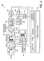
- Fig. 1 illustrates the principle of high-frequency inverter technology, which is also known as direct voltage conversion. It thereby shows the principle components of a conventional multi-pulse high-voltage generator used for providing the supply voltage of an X-ray tube 112.
- an intermediate DC voltage U LPF with more or less ripple is generated by rectifying and low-pass filtering an AC voltage U Mains which is supplied by the mains, thereby using an AC/DC converter stage 101 followed by a first low-pass filtering stage 102, wherein the latter may simply be realized by a single smoothing capacitor.
- the electric output power will naturally differ, the same high-voltage quality can be obtained from a single-phase power source as from a three-phase power source.
- a DC/AC power inverter stage 103 post-connected to said low-pass filtering stage 102 uses the intermediate DC voltage to generate a high-frequency alternating voltage U inv feeding a dedicated high-voltage transformer 104 which is connected on its secondary side to a high-voltage rectifier 105 and a subsequent second low-pass filtering stage 106, wherein the latter may also be realized by a single smoothing capacitor.
- the obtained output voltage U out may then be used as a high-frequency multi-pulse tube voltage for generating X-radiation in the X-ray tube 112.
- high-frequency inverters normally apply pulse-width modulation or act as a resonant circuit type depending on the power switches used.
- pulse-width modulation or act as a resonant circuit type depending on the power switches used.
- transformation of high-frequency AC voltages yields a very small high-voltage transformer volume.
- Electronic X-ray tube voltage control units thereby typically exhibit a response time of 0.1 ms or less.
- FIG. 2 A closed-loop control circuit for illustrating the principle of X-ray tube voltage and tube current control as known from the prior art is shown in Fig. 2 .
- an actual value U act of X-ray tube voltage is measured and compared to a nominal value U nom selected by the operator at the control console in a comparator circuit.
- the power switches are adjusted in a predefined manner (such as e.g. described in WO 2006/114719 A1 ).
- the speed of this control depends mainly on the inverter frequency. Although it is not quite as fast as constant potential high-voltage generators, the inverter easily exceeds the speed of conventional multi-peak rectifiers.
- the ripple in the resulting voltage on the secondary side of the transformer is influenced mainly by the inverter frequency, the internal smoothing capacity, the capacity of the high-voltage supply cables and the level of the intermediate DC voltage U LPF .
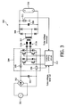
- FIG. 3 An analog implementation of an inverter-type high-voltage generator according to the prior art as described with reference to Fig. 1 , which may e.g. be used in a medical X-ray system, is shown in Fig. 3 .
- an AC voltage supplied from the mains is rectified and smoothed by a full-wave rectifier 302 and a smoothing capacitor 303 into an intermediate DC voltage and then supplied to a DC/AC full-bridge power inverter stage 304 consisting of four bipolar high-power switching transistors.
- a fuse 305 is connected to one end of the input side of the inverter circuit 304, and a current detector 306 is connected to the other end of the inverter circuit 304.
- a DC input voltage is converted into a high-frequency AC voltage (e.g., 200 kHz) by means of inverter circuit 304.
- said AC voltage is transformed into an AC voltage of a higher level (e.g., 150 kV) by means of a high-voltage transformer 307 which is then rectified and smoothed by a high-voltage rectifier 308 and a smoothing capacitor 309.
- Said high-voltage rectifier 308 may be given by a silicon rectifier with a breakdown voltage of about 150 kV, etc.
- the obtained DC high voltage is applied to an X-ray tube 310.
- a voltage dividing resistor 311 is connected in parallel with the capacitor 309.
- a voltage across the voltage dividing resistor 311 is fed back to an inverter driving circuit 312 which is used for controlling the switching timing of the inverter circuit 304.
- a detection value of the inverter current detector 306 the detection value of the tube voltage, a set value for setting the tube voltage as well as a set value (exposure time) for setting a timer are fed. These values are respectively input via a console (not shown) of the X-ray system. As depicted in Fig. 3 , the inverter driving circuit 312 generates an output signal which drives the switching transistors of the inverter circuit 304.
- CT or X-ray high-voltage generators preferably consist of DC/AC full-bridge power inverter stages which are connected to a series resonant circuit for driving the high-voltage transformer (cf. Fig. 4 ).
- a series resonant circuit for driving the high-voltage transformer cf. Fig. 4 .
- an analog circuitry of a resonant DC/DC power converter circuit for supplying an output power for use in a high-voltage generator circuitry with two independent DC/AC power inverter stages as known from WO 2006/114719 A1 is shown.
- two inverter circuits 402a+b can work on one high-voltage transformer 404 with multiple windings.
- WO 2006/114719 A1 thereby describes a control method that realizes zero current switching under all circumstances in combination with an innovative controller to simultaneously control the high output voltage.
- Fig. 5 shows a schematic diagram of the two independently controlled DC/AC power inverter stages whose outputs are serially connected to a series resonant circuit and either the first or the second winding of the interphase transformer, wherein the latter ensures a current symmetrization between the two independently operating DC/AC power inverter stages.
- interphase transformer 406 ensures a symmetrization of the inverter's AC output currents as long as no saturation effects take place.
- interphase transformer 406 works as an inductive voltage divider. Because it does not have an air gap, difference in the inverter output currents is very small as long as said interphase transformer is not saturated. This current corresponds to the magnetizing current of a common transformer. Saturation can be produced if the integral over time of the voltage differences of the two DC/AC power inverter stages exceeds a limit, defined by the maximum flux linkage of the interphase transformer. When this happens, current difference between the two DC/AC power inverter stages will increase.
- a control algorithm is introduced to minimize the current difference of inverter currents, which has the effect that the integral of voltage difference of the two DC/AC power inverter stages' output voltages over the time is minimized.
- all the advantages of the controller structure described in WO 2006/114719 A1 can be maintained.
- WO 2006/114719 A1 three different operating modes are described, denoted by a plus sign (for increasing the amplitude of the resonant current, e.g. having the inverter voltage in phase with the resonant current), a zero sign (e.g. applying zero voltage, having a maintaining effect on the amplitude of the resonant current), and a minus sign (for reducing the amplitude of the resonant current, e.g. having the inverter voltage opposite to the current).
- a plus sign for increasing the amplitude of the resonant current, e.g. having the inverter voltage in phase with the resonant current
- a zero sign e.g.
- Fig. 4 which corresponds to Fig. 11 as contained and described in reference document WO 2006/114719 A1 , shows a schematic diagram on how two inverter circuits can work on one transformer having multiple windings. This allows two additional switching modes resulting from the combination of a plus state or minus state in one inverter with a zero state in the other inverter. The resulting five levels are categorized as +1, +1/2, 0, -1/2 and -1. All possible combinations of operation modes having two DC/AC power inverter stages working on one high-voltage transformer are depicted in the table as depicted in Fig. 6 , which corresponds to Fig. 12 from reference document WO 2006/114719 A1 .
- One method to symmetrize the inverter currents is to compare their difference, for example by subtracting second inverter's output current ( I 2 ) from the output current of said first inverter ( I 1 ) with a simple operational amplifier circuit and comparing it to zero or by directly comparing both signals. The resulting digital signal indicates which of the currents is larger.
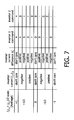
- Fig. 7 shows a truth table which illustrates the proposed control algorithm for minimizing the current difference.
- controller algorithm uses the redundant operation modes to control the DC/AC power inverter stages in a way that the resulting current difference is reduced. This is of course only possible for the +1/2 and the -1/2 level.
- the control algorithm checks the different currents to choose an advantageous combination of the inverter operating modes to minimize the aforementioned different current as much as possible. Remaining differences are then compensated by the interphase transformer. It is a special advantage that such an interphase transformer also balances spreads in other components and inequalities between the inverter modules.
- the present invention is not limited to DC/DC power converter circuits with only two DC/AC power inverter stages that are to be symmetrized by being inductively coupled by a first and a second winding of an interphase transformer which is designed to balance differences in the output currents of the two inverter stages. It may advantageously be foreseen to symmetrize more than two DC/AC power inverter stages by providing an adequate number of interphase transformers for inductively coupling the outputs of each pair of these inverter stages. For a given number of N DC/AC power inverter stages, it can be shown that at least (N-1) interphase transformers have to be used to accomplish this task.
- FIG. 9 A flow chart for illustrating the method for controlling a resonant DC/DC power converter circuit for supplying an output power for use in a high-voltage generator circuitry of an X-ray radiographic imaging system, 3D rotational angiography device or X-ray computed tomography device of the fan- or cone-beam type as claimed in the present invention is shown in Fig. 9 .
- the two inverters' resonant AC output currents I 1 and I 2 are continuously detected (S2b) while symmetrizing (S2a) the current flows at the output ports of the two DC/AC inverter stages 402a+b by using interphase transformer 406. Otherwise, the procedure is continued in a loop with step S 1 after a predefined delay time ⁇ t until such a switching command has been received.
- the magnitude of a current difference ⁇ I which is obtained by subtracting the resonant current I 2 at the output port of a second one (402b) of the two DC/AC inverter stages 402a+b from the resonant current I 1 at the output port of a first one (402a) of these two DC/AC inverter stages is calculated (S3), and thereupon, which means dependent on the calculated difference ⁇ I of the detected inverter output currents I 1 and I 2 , the switching states and/or switching times of the two DC/AC inverter stages 402a+b are controlled (S4) in such a way that said current difference takes on a minimum value which ensures that the interphase transformer 406 is not operated in a saturated state.
- S5 a switching command (power-off signal) for terminating the running X-ray imaging session, the procedure terminates. Otherwise, it is continued with steps S2a and S2b.
- An immediate application of the claimed DC/DC power converter circuit consists in proceeding the development of high-voltage generators, especially voltage generators with very high power density that may advantageously be used as a voltage supply for next generation X-ray tubes. Aside therefrom, the invention may also be usefully applied for proceeding the development of DC/DC power converter circuit technology in general.
Landscapes
- Engineering & Computer Science (AREA)
- Power Engineering (AREA)
- X-Ray Techniques (AREA)
- Apparatus For Radiation Diagnosis (AREA)
Claims (14)
- Steuergerät für einen Wechselrichter einer resonanten Stromwandlungsschaltung (400),
wobei die genannte Stromwandlungsschaltung (400) zwei unabhängige Wechselrichterstufen (402a+b) zum Versorgen eines Transformators (404) mit mehreren Primärwicklungen umfasst und wobei die genannten Wechselrichterstufen (402a+b) durch eine erste und eine zweite Wicklung einer Saugdrossel (406) induktiv gekoppelt sind, die so ausgelegt ist, dass sie Unterschiede in den Ausgangsströmen (I 1, I2) der beiden Wechselrichterstufen (402a+b) ausgleicht,
wobei das genannte Steuergerät für einen Wechselrichter so ausgelegt ist, dass es die Größe des Differenzwertes (ΔI) der Ausgangsströme des Wechselrichters auf einen Wert minimiert, der sicherstellt, dass die Saugdrossel (406) nicht in einem gesättigten Zustand betrieben wird, indem es die Schaltzustände und/oder Schaltzeiten der Wechselrichterstufen (402a+b) in Abhängigkeit von dieser Stromdifferenz (ΔI) steuert und so einen stromfreien Betrieb ermöglicht. - Steuergerät für einen Wechselrichter nach Anspruch 1,
wobei die erste Wicklung der Saugdrossel (406) mit mindestens einem resonanten Tankkreis (403a, 403a') in Reihe geschaltet ist, der am Ausgangsanschluss einer ersten der genannten Wechselrichterstufen (402a) mit einer ersten Primärwicklung des Mehrwicklungstransformators (404) in Reihe geschaltet ist, und wobei die zweite Wicklung der Saugdrossel (406) mit mindestens einem weiteren resonanten Tankkreis (403b, 403b') in Reihe geschaltet ist, der mit einer zweiten Primärwicklung des Mehrwicklungstransformators (404) in Reihe geschaltet ist. - Steuergerät für einen Wechselrichter nach einem der Ansprüche 1 bis 2,
wobei die genannte resonante Stromwandlungsschaltung (400) ein DC/DC-Wandler für den Einsatz in einem Hochspannungs-Generatorschaltkreis ist. - Steuergerät für einen Wechselrichter nach Anspruch 3,
wobei der genannte Transformator (404) mit mehreren Primärwicklungen für Hochspannungsbetrieb ausgelegt ist. - Steuergerät für einen Wechselrichter nach Anspruch 4,
wobei der genannte Hochspannungs-Generatorschaltkreis zur Zuführung eines Ausgangsstroms zu einem Röntgen-Bildgebungssystem, einer dreidimensionalen Rotationsangiographie-Vorrichtung oder einer Röntgencomputertomographie-Vorrichtung mit Fächerstrahl- oder Kegelstrahltechnik dient. - Resonante Stromwandlungsschaltung (400), die Folgendes umfasst:zwei unabhängige Wechselrichterstufen (402a+b) zum Versorgen eines Transformators (404) mit mehreren Primärwicklungen, wobei die genannten Wechselrichterstufen (402a+b) durch eine erste und eine zweite Wicklung einer Saugdrossel (406) induktiv gekoppelt sind, die so ausgelegt ist, dass sie Unterschiede in den Ausgangsströmen (I 1, I 2) der beiden Wechselrichterstufen (402a+b) ausgleicht,wobei die genannte resonante Stromwandlungsschaltung (400) ferner ein Steuergerät für einen Wechselrichter nach Anspruch 1 umfasst.
- Resonante Stromwandlungsschaltung (400) nach Anspruch 6,
wobei die erste Wicklung der Saugdrossel (406) mit mindestens einem resonanten Tankkreis (403a, 403a') in Reihe geschaltet ist, der am Ausgangsanschluss einer ersten der genannten Wechselrichterstufen (402a) mit einer ersten Primärwicklung des Mehrwicklungstransformators (404) in Reihe geschaltet ist, und wobei die zweite Wicklung der Saugdrossel (406) mit mindestens einem weiteren resonanten Tankkreis (403b, 403b') in Reihe geschaltet ist, der mit einer zweiten Primärwicklung des Mehrwicklungstransformators (404) in Reihe geschaltet ist. - Resonante Stromwandlungsschaltung (400) nach einem der Ansprüche 6 bis 7,
wobei die genannte resonante Stromwandlungsschaltung (400) ein DC/DC-Wandler für den Einsatz in einem Hochspannungs-Generatorschaltkreis ist. - Resonante Stromwandlungsschaltung (400) nach Anspruch 8,
wobei der genannte Transformator (404) mit mehreren Primärwicklungen für Hochspannungsbetrieb ausgelegt ist. - Resonante Stromwandlungsschaltung (400) nach Anspruch 9,
wobei der genannte Hochspannungs-Generatorschaltkreis zur Zuführung eines Ausgangsstroms zu einem Röntgen-Bildgebungssystem, einer dreidimensionalen Rotationsangiographie-Vorrichtung oder einer Röntgencomputertomographie-Vorrichtung mit Fächerstrahl- oder Kegelstrahltechnik dient. - Röntgen-Bildgebungssystem, dreidimensionale Rotationsangiographie-Vorrichtung oder Röntgencomputertomographie-Vorrichtung mit Fächerstrahl- oder Kegelstrahltechnik
mit einer resonanten Stromwandlungsschaltung (400) nach Anspruch 6, zum Zuführen eines Ausgangsstroms zur Verwendung in einem Hochspannungs-Generatorschaltkreis, der der genannten Computertomographievorrichtung oder dem genannten Röntgensystem eine Versorgungsspannung zum Betrieb einer Röntgenröhre liefert. - Röntgen-Bildgebungssystem, dreidimensionale Rotationsangiographie-Vorrichtung oder Röntgencomputertomographie-Vorrichtung mit Fächerstrahl- oder Kegelstrahltechnik nach Anspruch 11,
wobei die erste Wicklung der Saugdrossel (406) mit mindestens einem resonanten Tankkreis (403a, 403a') in Reihe geschaltet ist, der am Ausgangsanschluss einer ersten der genannten Wechselrichterstufen (402a) mit einer ersten Primärwicklung des Mehrwicklungstransformators (404) in Reihe geschaltet ist, und wobei die zweite Wicklung der Saugdrossel (406) mit mindestens einem weiteren resonanten Tankkreis (403b, 403b') in Reihe geschaltet ist, der mit einer zweiten Primärwicklung des Mehrwicklungstransformators (404) in Reihe geschaltet ist. - Verfahren zum Steuern einer resonanten Stromwandlungsschaltung (400) zum Zuführen eines Ausgangsstroms zur Verwendung in einem Hochspannungs-Generatorschaltkreis eines Röntgen-Bildgebungssystems, einer dreidimensionale Rotationsangiographie-Vorrichtung oder einer Röntgencomputertomographie-Vorrichtung mit Fächerstrahl- oder Kegelstrahltechnik, wobei die genannte resonante Stromwandlungsschaltung (400) zwei unabhängige Wechselrichterstufen (402a+b) zum Versorgen eines Transformators (404) mit mehreren Primärwicklungen umfasst und die genannten Wechselrichterstufen (402a+b) durch eine erste und eine zweite Wicklung einer Saugdrossel (406) induktiv gekoppelt sind, die so ausgelegt ist, dass sie Unterschiede in den Ausgangsströmen (I 1, I 2) der beiden Wechselrichterstufen (402a+b) ausgleicht, wobei die genannte erste Wicklung am Ausgangsanschluss einer ersten der genannten Wechselrichterstufen (402a) mit einer ersten Primärwicklung des Mehrwicklungstransformators (404) in Reihe geschaltet ist und wobei die genannte zweite Wicklung mit einer zweiten Primärwicklung des Mehrwicklungstransformators (404) in Reihe geschaltet ist,
wobei das genannte Verfahren die folgenden Schritte umfasst:- kontinuierliches Detektieren (S2a) der Ausgangsströme (I 1, I 2) der beiden Wechselrichterstufen während einer gestarteten Röntgen-Bildgebungssitzung und gleichzeitiges Symmetrisieren (S2b) der Stromflüsse an den Ausgangsanschlüssen der beiden Wechselrichterstufen (402a+b) durch die Verwendung der genannten Saugdrossel (406),- Berechnen (S3) der Größe einer Stromdifferenz (ΔI), die durch das Subtrahieren des resonanten Stroms (I 2) am Ausgangsanschluss einer zweiten (402b) der beiden Wechselrichterstufen (402a+b) von dem resonanten Strom (I 1) am Ausgangsanschluss der ersten (402a) dieser beiden Wechselrichterstufen (402a+b) erzielt wird, und- Steuern (S4) der Schaltzustände und/oder Schaltzeiten der beiden Wechselrichterstufen (402a+b) in Abhängigkeit von der berechneten Differenz (ΔI) der detektierten Ausgangsströme (I 1, I 2) der Wechselrichter derart, dass die genannte Stromdifferenz einen minimalen Wert annimmt, der sicherstellt, dass die Saugdrossel (406) nicht im gesättigten Zustand betrieben wird, und somit einen stromfreien Betrieb ermöglicht. - Computerprogrammprodukt, das so ausgelegt ist, dass es das Verfahren zum Steuern einer resonanten Stromwandlungsschaltung (400) nach Anspruch 13 durchführt.
Priority Applications (1)
| Application Number | Priority Date | Filing Date | Title |
|---|---|---|---|
| EP09717168A EP2263302B1 (de) | 2008-03-06 | 2009-03-03 | Steuereinheit für einen gleichstrom-wechselstrom-wandler einer resonanten stromwandlungsschaltung, insbesondere für einen gleichstrom-wechselstrom-wandler zur verwendung in einem hochspannungsgeneratorschaltkreis einer modernen computertomographievorrichtung oder eines röntgensystems |
Applications Claiming Priority (3)
| Application Number | Priority Date | Filing Date | Title |
|---|---|---|---|
| EP08102354 | 2008-03-06 | ||
| EP09717168A EP2263302B1 (de) | 2008-03-06 | 2009-03-03 | Steuereinheit für einen gleichstrom-wechselstrom-wandler einer resonanten stromwandlungsschaltung, insbesondere für einen gleichstrom-wechselstrom-wandler zur verwendung in einem hochspannungsgeneratorschaltkreis einer modernen computertomographievorrichtung oder eines röntgensystems |
| PCT/IB2009/050839 WO2009109902A2 (en) | 2008-03-06 | 2009-03-03 | Dc/ac power inverter control unit of a resonant power converter circuit, in particular a dc/dc converter for use in a high-voltage generator circuitry of a modern computed tomography device or x-ray radiographic system |
Publications (2)
| Publication Number | Publication Date |
|---|---|
| EP2263302A2 EP2263302A2 (de) | 2010-12-22 |
| EP2263302B1 true EP2263302B1 (de) | 2012-02-08 |
Family
ID=40933763
Family Applications (1)
| Application Number | Title | Priority Date | Filing Date |
|---|---|---|---|
| EP09717168A Not-in-force EP2263302B1 (de) | 2008-03-06 | 2009-03-03 | Steuereinheit für einen gleichstrom-wechselstrom-wandler einer resonanten stromwandlungsschaltung, insbesondere für einen gleichstrom-wechselstrom-wandler zur verwendung in einem hochspannungsgeneratorschaltkreis einer modernen computertomographievorrichtung oder eines röntgensystems |
Country Status (6)
| Country | Link |
|---|---|
| US (1) | US8385504B2 (de) |
| EP (1) | EP2263302B1 (de) |
| CN (1) | CN101960708B (de) |
| AT (1) | ATE545194T1 (de) |
| RU (1) | RU2499349C2 (de) |
| WO (1) | WO2009109902A2 (de) |
Cited By (2)
| Publication number | Priority date | Publication date | Assignee | Title |
|---|---|---|---|---|
| CN106100346A (zh) * | 2016-07-08 | 2016-11-09 | 北京交通大学 | 一种具有均压均流功能的组合式谐振变换器 |
| EP4396932A4 (de) * | 2021-10-19 | 2025-01-08 | Shanghai United Imaging Healthcare Co., Ltd. | Vorrichtung zur stromversorgung und medizinische vorrichtung |
Families Citing this family (43)
| Publication number | Priority date | Publication date | Assignee | Title |
|---|---|---|---|---|
| EP2023475B1 (de) * | 2007-08-04 | 2016-10-12 | SMA Solar Technology AG | Wechselrichter für eine geerdete Gleichspannungsquelle, insbesondere einen Photovoltaikgenerator |
| JP5332031B2 (ja) * | 2008-03-31 | 2013-11-06 | 株式会社小松製作所 | トランス結合型昇圧器のスイッチング制御方法 |
| JP5250915B2 (ja) * | 2009-04-03 | 2013-07-31 | 株式会社小松製作所 | トランス結合型昇圧器の制御装置 |
| EP2299580A3 (de) * | 2009-06-24 | 2011-07-27 | STMicroelectronics S.r.l. | Mehrphasenresonanzwandler und Steuerungsverfahren dafür |
| GB2475518A (en) * | 2009-11-20 | 2011-05-25 | Technelec Ltd | Two stage resonant converter for LED lamps |
| CN101765290B (zh) * | 2009-12-07 | 2012-12-26 | 芜湖国睿兆伏电子股份有限公司 | 一种用于x射线机的高压发生器及其控制方法 |
| JP5666485B2 (ja) * | 2010-02-09 | 2015-02-12 | 株式会社日立メディコ | 電力変換装置、x線ct装置およびx線撮影装置 |
| AU2011217688A1 (en) * | 2010-02-18 | 2012-10-11 | Peter Waldemar Lehn | DC-DC converter circuit for high input-to-output voltage conversion |
| US9059636B2 (en) | 2010-02-18 | 2015-06-16 | Peter Waldemar Lehn | DC-DC converter circuit using LLC circuit in the region of voltage gain above unity |
| JP5678344B2 (ja) * | 2010-07-13 | 2015-03-04 | ミネベア株式会社 | スイッチング電源装置の制御方法 |
| US9131592B2 (en) * | 2010-11-18 | 2015-09-08 | Hitachi Medical Corporation | Mobile X-ray apparatus |
| WO2012149387A1 (en) * | 2011-04-27 | 2012-11-01 | Solarbridge Technologies, Inc. | Configurable power supply assembly |
| US8174856B2 (en) | 2011-04-27 | 2012-05-08 | Solarbridge Technologies, Inc. | Configurable power supply assembly |
| CN202404169U (zh) * | 2011-12-19 | 2012-08-29 | 哈尔滨九洲电气股份有限公司 | 串联叠加电压型的高压变频器的低压测试装置 |
| EP2803133A2 (de) * | 2012-01-12 | 2014-11-19 | Koninklijke Philips N.V. | Wechselrichter mit geringerer anzahl an dämpferkondensatoren |
| JP6335889B2 (ja) * | 2012-06-19 | 2018-05-30 | コーニンクレッカ フィリップス エヌ ヴェKoninklijke Philips N.V. | 共振型dc−dcコンバータのための制御モード |
| US9072155B2 (en) * | 2012-06-22 | 2015-06-30 | Moxtek, Inc. | Transformer network |
| US20150180345A1 (en) * | 2012-07-19 | 2015-06-25 | Damien Frost | Multi-mode control of a full bridge resonant converter |
| CN103580494B (zh) | 2012-07-19 | 2016-04-20 | 台达电子工业股份有限公司 | 变流器系统 |
| JP6362865B2 (ja) * | 2013-01-10 | 2018-07-25 | キヤノンメディカルシステムズ株式会社 | X線コンピュータ断層撮影装置及びx線発生装置 |
| US8941961B2 (en) | 2013-03-14 | 2015-01-27 | Boulder Wind Power, Inc. | Methods and apparatus for protection in a multi-phase machine |
| US9247595B2 (en) * | 2013-06-11 | 2016-01-26 | Enphase Energy, Inc. | LED lighting converter |
| WO2015005380A1 (ja) * | 2013-07-11 | 2015-01-15 | 株式会社日立メディコ | 高電圧発生装置およびx線発生装置 |
| US9119592B2 (en) * | 2013-09-03 | 2015-09-01 | General Electric Company | Interleaved resonant converter |
| WO2015158699A1 (en) * | 2014-04-15 | 2015-10-22 | Danmarks Tekniske Universitet | A resonant dc-dc power converter assembly |
| CN105228326B (zh) * | 2014-06-26 | 2018-10-23 | 锐珂(上海)医疗器材有限公司 | X射线发生器及用于监控x射线发生器的方法 |
| EP3034001B1 (de) * | 2014-12-18 | 2017-10-18 | Schleifring und Apparatebau GmbH | Induktiver Drehübertrager mit sekundärer Sicherheitsschaltung |
| WO2017005505A1 (en) * | 2015-07-09 | 2017-01-12 | Broadband Power Solutions S.A. | High power density inverter (ii) |
| CN106469992B (zh) * | 2015-08-05 | 2018-10-02 | 维谛技术有限公司 | 一种防止耦合电抗器磁饱和的控制方法和装置 |
| US10050531B1 (en) * | 2017-01-24 | 2018-08-14 | General Electric Company | Direct flux control power converter |
| RU2688147C2 (ru) * | 2017-06-28 | 2019-05-20 | Федеральное государственное казенное военное образовательное учреждение высшего образования "Военный учебно-научный центр Военно-Морского Флота "Военно-морская академия им. Адмирала Флота Советского Союза Н.Г. Кузнецова" | Автономный источник электрической энергии |
| CN109390118B (zh) * | 2017-08-03 | 2021-06-11 | 台达电子工业股份有限公司 | 磁性组件及其适用的电源转换装置 |
| US10645787B2 (en) * | 2017-12-13 | 2020-05-05 | General Electric Company | System and method for providing electrical power to a load |
| WO2019120589A1 (en) * | 2017-12-22 | 2019-06-27 | Heliox B.V. | A charging system and a method of charging an electrical energy storage device |
| EP3661038A1 (de) * | 2018-11-30 | 2020-06-03 | Infineon Technologies Austria AG | Bidirektionaler resonanzleistungswandler mit zwei tankkreisen auf einer seite eines transformators |
| US11025173B2 (en) * | 2019-02-04 | 2021-06-01 | Ford Global Technologies, Llc | Vehicle power control systems |
| CN111313657B (zh) * | 2020-03-05 | 2021-03-02 | 中车株洲电力机车研究所有限公司 | 一种降低变流器输出电压变化率的电路及控制方法 |
| US11463011B1 (en) * | 2020-07-15 | 2022-10-04 | Solid State Power LLC | High voltage converter with switch modules parallel driving a single transformer primary |
| US12132406B2 (en) | 2020-07-15 | 2024-10-29 | Solid State Power LLC | High and medium voltage power converters with switch modules parallel driving a single transformer primary |
| CN113162416B (zh) * | 2021-05-11 | 2023-12-12 | 有方(合肥)医疗科技有限公司 | 多路独立高压输出装置、x射线设备及控制方法 |
| EP4092895A1 (de) * | 2021-05-18 | 2022-11-23 | Siemens Energy Global GmbH & Co. KG | Verfahren zum betrieb eines gleichstromstellers zur versorgung einer elektrolyseeinrichtung mit elektrischer betriebsenergie |
| US12131722B2 (en) | 2021-09-23 | 2024-10-29 | Matthew T. Patterson | Wearable music system |
| EP4175099A1 (de) * | 2021-10-28 | 2023-05-03 | Siemens Healthcare GmbH | Energieversorgungsschaltkreis für ein röntgenstrahlerzeugungssystem |
Family Cites Families (12)
| Publication number | Priority date | Publication date | Assignee | Title |
|---|---|---|---|---|
| DE59203309D1 (de) | 1991-06-19 | 1995-09-21 | Ant Nachrichtentech | Schaltregler. |
| US5245525A (en) | 1991-10-24 | 1993-09-14 | Sundstrand Corporation | DC current control through an interphase transformer using differential current sensing |
| RU2095947C1 (ru) * | 1995-01-05 | 1997-11-10 | Институт электрофизики Уральского отделения РАН | Малогабаритный импульсный рентгеновский аппарат |
| AT406625B (de) | 1998-11-12 | 2000-07-25 | Fronius Schweissmasch | Spannungsumschaltvorrichtung |
| DE19934749A1 (de) | 1998-11-27 | 2000-05-31 | Siemens Ag | Antriebssystem für ein Walzgerüst in einer Walzstrasse |
| DE60124713T2 (de) * | 2000-05-10 | 2007-09-13 | Hitachi Medical Corp. | Röntgengenerator und denselbigen enthaltende röntgen-ct-vorrichtung |
| DE10038814A1 (de) * | 2000-08-09 | 2002-02-21 | Abb Research Ltd | Hochspannungs-Gleichstromwandler |
| US6392902B1 (en) * | 2000-08-31 | 2002-05-21 | Delta Electronics, Inc. | Soft-switched full-bridge converter |
| EP1878107B1 (de) | 2005-04-26 | 2012-08-15 | Koninklijke Philips Electronics N.V. | Dc-dc-resonanzwandler mit stromloser schaltung |
| EP2013963B1 (de) | 2006-04-25 | 2012-08-01 | Philips Intellectual Property & Standards GmbH | Wechselrichtersteuervorrichtung für schaltpunktbestimmung |
| RU2316884C2 (ru) * | 2006-07-20 | 2008-02-10 | ОБЩЕСТВО С ОГРАНИЧЕННОЙ ОТВЕТСТВЕННОСТЬЮ "Нью Лайн" | Преобразователь напряжения |
| CN201001088Y (zh) * | 2006-12-11 | 2008-01-02 | 王金 | 一种用于逆变器轻载零电压零电流开关的辅助变压器电路 |
-
2009
- 2009-03-03 WO PCT/IB2009/050839 patent/WO2009109902A2/en not_active Ceased
- 2009-03-03 CN CN2009801078566A patent/CN101960708B/zh not_active Expired - Fee Related
- 2009-03-03 RU RU2010140800/07A patent/RU2499349C2/ru not_active IP Right Cessation
- 2009-03-03 AT AT09717168T patent/ATE545194T1/de active
- 2009-03-03 EP EP09717168A patent/EP2263302B1/de not_active Not-in-force
- 2009-03-03 US US12/920,321 patent/US8385504B2/en not_active Expired - Fee Related
Cited By (2)
| Publication number | Priority date | Publication date | Assignee | Title |
|---|---|---|---|---|
| CN106100346A (zh) * | 2016-07-08 | 2016-11-09 | 北京交通大学 | 一种具有均压均流功能的组合式谐振变换器 |
| EP4396932A4 (de) * | 2021-10-19 | 2025-01-08 | Shanghai United Imaging Healthcare Co., Ltd. | Vorrichtung zur stromversorgung und medizinische vorrichtung |
Also Published As
| Publication number | Publication date |
|---|---|
| WO2009109902A2 (en) | 2009-09-11 |
| RU2499349C2 (ru) | 2013-11-20 |
| RU2010140800A (ru) | 2012-04-20 |
| CN101960708B (zh) | 2013-11-20 |
| WO2009109902A3 (en) | 2009-11-05 |
| ATE545194T1 (de) | 2012-02-15 |
| US20110002445A1 (en) | 2011-01-06 |
| EP2263302A2 (de) | 2010-12-22 |
| US8385504B2 (en) | 2013-02-26 |
| CN101960708A (zh) | 2011-01-26 |
Similar Documents
| Publication | Publication Date | Title |
|---|---|---|
| EP2263302B1 (de) | Steuereinheit für einen gleichstrom-wechselstrom-wandler einer resonanten stromwandlungsschaltung, insbesondere für einen gleichstrom-wechselstrom-wandler zur verwendung in einem hochspannungsgeneratorschaltkreis einer modernen computertomographievorrichtung oder eines röntgensystems | |
| US8309878B2 (en) | Universal input power supply utilizing parallel power modules | |
| US9748865B2 (en) | Power conversion device and three-phase alternating current power supply device | |
| US11205952B2 (en) | Methods and systems for controlling current source rectifiers | |
| JP2019525700A (ja) | 高周波数高電力コンバータシステム | |
| JPH0851790A (ja) | 誘導性負荷用制御回路 | |
| US9831676B2 (en) | Power conversion device and three-phase AC power supply device | |
| JP2015520602A (ja) | 共振型dc−dcコンバータのための制御モード | |
| US20140241507A1 (en) | Electrical energy supply system | |
| US11791718B2 (en) | Power converting device | |
| US7433216B2 (en) | Voltage control and harmonic minimization of multi-level converter | |
| JP2017011870A (ja) | Dc/dcコンバータ | |
| KR102024606B1 (ko) | 전력 변환 장치 및 그 제어 방법 | |
| KR20110135126A (ko) | 캐스케이드 멀티레벨 고압인버터의 돌입전류 방지장치 | |
| KR20180085999A (ko) | 고조파 제어 전원 장치, 이를 포함하는 공기 조화기 및 고조파 제어 방법 | |
| KR0179096B1 (ko) | 반도체소자를 사용하여 강압형 쵸퍼와 인버터로 구성한 X-ray용 고주파 공진형 고전압 발생장치 | |
| JP5169679B2 (ja) | 共振型電力変換装置 | |
| JP3193809B2 (ja) | 三相整流装置 | |
| JPH07263175A (ja) | インバータ式x線高電圧装置 | |
| JP3644610B2 (ja) | インバータ式x線高電圧装置 | |
| JPH0765987A (ja) | インバータ式x線高電圧装置 | |
| JP2002315355A (ja) | 電力変換装置 | |
| JPH07308069A (ja) | 昇圧形3相全波整流装置及びその制御方法 | |
| JPH07272891A (ja) | インバータ式x線高電圧装置 | |
| KR20190121608A (ko) | 전류제어를 통해 리플을 저감시키는 병렬 정류기 |
Legal Events
| Date | Code | Title | Description |
|---|---|---|---|
| PUAI | Public reference made under article 153(3) epc to a published international application that has entered the european phase |
Free format text: ORIGINAL CODE: 0009012 |
|
| 17P | Request for examination filed |
Effective date: 20101006 |
|
| AK | Designated contracting states |
Kind code of ref document: A2 Designated state(s): AT BE BG CH CY CZ DE DK EE ES FI FR GB GR HR HU IE IS IT LI LT LU LV MC MK MT NL NO PL PT RO SE SI SK TR |
|
| AX | Request for extension of the european patent |
Extension state: AL BA RS |
|
| 17Q | First examination report despatched |
Effective date: 20110302 |
|
| DAX | Request for extension of the european patent (deleted) | ||
| GRAP | Despatch of communication of intention to grant a patent |
Free format text: ORIGINAL CODE: EPIDOSNIGR1 |
|
| GRAS | Grant fee paid |
Free format text: ORIGINAL CODE: EPIDOSNIGR3 |
|
| GRAA | (expected) grant |
Free format text: ORIGINAL CODE: 0009210 |
|
| AK | Designated contracting states |
Kind code of ref document: B1 Designated state(s): AT BE BG CH CY CZ DE DK EE ES FI FR GB GR HR HU IE IS IT LI LT LU LV MC MK MT NL NO PL PT RO SE SI SK TR |
|
| REG | Reference to a national code |
Ref country code: GB Ref legal event code: FG4D |
|
| REG | Reference to a national code |
Ref country code: CH Ref legal event code: EP Ref country code: AT Ref legal event code: REF Ref document number: 545194 Country of ref document: AT Kind code of ref document: T Effective date: 20120215 |
|
| REG | Reference to a national code |
Ref country code: DE Ref legal event code: R096 Ref document number: 602009005245 Country of ref document: DE Effective date: 20120405 |
|
| REG | Reference to a national code |
Ref country code: DE Ref legal event code: R084 Ref document number: 602009005245 Country of ref document: DE Effective date: 20120214 |
|
| REG | Reference to a national code |
Ref country code: GB Ref legal event code: 746 Effective date: 20120416 |
|
| REG | Reference to a national code |
Ref country code: NL Ref legal event code: VDEP Effective date: 20120208 |
|
| LTIE | Lt: invalidation of european patent or patent extension |
Effective date: 20120208 |
|
| PG25 | Lapsed in a contracting state [announced via postgrant information from national office to epo] |
Ref country code: LT Free format text: LAPSE BECAUSE OF FAILURE TO SUBMIT A TRANSLATION OF THE DESCRIPTION OR TO PAY THE FEE WITHIN THE PRESCRIBED TIME-LIMIT Effective date: 20120208 Ref country code: HR Free format text: LAPSE BECAUSE OF FAILURE TO SUBMIT A TRANSLATION OF THE DESCRIPTION OR TO PAY THE FEE WITHIN THE PRESCRIBED TIME-LIMIT Effective date: 20120208 Ref country code: NO Free format text: LAPSE BECAUSE OF FAILURE TO SUBMIT A TRANSLATION OF THE DESCRIPTION OR TO PAY THE FEE WITHIN THE PRESCRIBED TIME-LIMIT Effective date: 20120508 Ref country code: NL Free format text: LAPSE BECAUSE OF FAILURE TO SUBMIT A TRANSLATION OF THE DESCRIPTION OR TO PAY THE FEE WITHIN THE PRESCRIBED TIME-LIMIT Effective date: 20120208 Ref country code: IS Free format text: LAPSE BECAUSE OF FAILURE TO SUBMIT A TRANSLATION OF THE DESCRIPTION OR TO PAY THE FEE WITHIN THE PRESCRIBED TIME-LIMIT Effective date: 20120608 |
|
| PG25 | Lapsed in a contracting state [announced via postgrant information from national office to epo] |
Ref country code: GR Free format text: LAPSE BECAUSE OF FAILURE TO SUBMIT A TRANSLATION OF THE DESCRIPTION OR TO PAY THE FEE WITHIN THE PRESCRIBED TIME-LIMIT Effective date: 20120509 Ref country code: LV Free format text: LAPSE BECAUSE OF FAILURE TO SUBMIT A TRANSLATION OF THE DESCRIPTION OR TO PAY THE FEE WITHIN THE PRESCRIBED TIME-LIMIT Effective date: 20120208 Ref country code: PT Free format text: LAPSE BECAUSE OF FAILURE TO SUBMIT A TRANSLATION OF THE DESCRIPTION OR TO PAY THE FEE WITHIN THE PRESCRIBED TIME-LIMIT Effective date: 20120608 Ref country code: BE Free format text: LAPSE BECAUSE OF FAILURE TO SUBMIT A TRANSLATION OF THE DESCRIPTION OR TO PAY THE FEE WITHIN THE PRESCRIBED TIME-LIMIT Effective date: 20120208 Ref country code: FI Free format text: LAPSE BECAUSE OF FAILURE TO SUBMIT A TRANSLATION OF THE DESCRIPTION OR TO PAY THE FEE WITHIN THE PRESCRIBED TIME-LIMIT Effective date: 20120208 Ref country code: PL Free format text: LAPSE BECAUSE OF FAILURE TO SUBMIT A TRANSLATION OF THE DESCRIPTION OR TO PAY THE FEE WITHIN THE PRESCRIBED TIME-LIMIT Effective date: 20120208 |
|
| REG | Reference to a national code |
Ref country code: AT Ref legal event code: MK05 Ref document number: 545194 Country of ref document: AT Kind code of ref document: T Effective date: 20120208 |
|
| PG25 | Lapsed in a contracting state [announced via postgrant information from national office to epo] |
Ref country code: CY Free format text: LAPSE BECAUSE OF FAILURE TO SUBMIT A TRANSLATION OF THE DESCRIPTION OR TO PAY THE FEE WITHIN THE PRESCRIBED TIME-LIMIT Effective date: 20120208 |
|
| PG25 | Lapsed in a contracting state [announced via postgrant information from national office to epo] |
Ref country code: CZ Free format text: LAPSE BECAUSE OF FAILURE TO SUBMIT A TRANSLATION OF THE DESCRIPTION OR TO PAY THE FEE WITHIN THE PRESCRIBED TIME-LIMIT Effective date: 20120208 Ref country code: MC Free format text: LAPSE BECAUSE OF NON-PAYMENT OF DUE FEES Effective date: 20120331 Ref country code: DK Free format text: LAPSE BECAUSE OF FAILURE TO SUBMIT A TRANSLATION OF THE DESCRIPTION OR TO PAY THE FEE WITHIN THE PRESCRIBED TIME-LIMIT Effective date: 20120208 Ref country code: RO Free format text: LAPSE BECAUSE OF FAILURE TO SUBMIT A TRANSLATION OF THE DESCRIPTION OR TO PAY THE FEE WITHIN THE PRESCRIBED TIME-LIMIT Effective date: 20120208 Ref country code: SE Free format text: LAPSE BECAUSE OF FAILURE TO SUBMIT A TRANSLATION OF THE DESCRIPTION OR TO PAY THE FEE WITHIN THE PRESCRIBED TIME-LIMIT Effective date: 20120208 Ref country code: EE Free format text: LAPSE BECAUSE OF FAILURE TO SUBMIT A TRANSLATION OF THE DESCRIPTION OR TO PAY THE FEE WITHIN THE PRESCRIBED TIME-LIMIT Effective date: 20120208 Ref country code: SI Free format text: LAPSE BECAUSE OF FAILURE TO SUBMIT A TRANSLATION OF THE DESCRIPTION OR TO PAY THE FEE WITHIN THE PRESCRIBED TIME-LIMIT Effective date: 20120208 |
|
| PG25 | Lapsed in a contracting state [announced via postgrant information from national office to epo] |
Ref country code: IT Free format text: LAPSE BECAUSE OF FAILURE TO SUBMIT A TRANSLATION OF THE DESCRIPTION OR TO PAY THE FEE WITHIN THE PRESCRIBED TIME-LIMIT Effective date: 20120208 Ref country code: SK Free format text: LAPSE BECAUSE OF FAILURE TO SUBMIT A TRANSLATION OF THE DESCRIPTION OR TO PAY THE FEE WITHIN THE PRESCRIBED TIME-LIMIT Effective date: 20120208 |
|
| PLBE | No opposition filed within time limit |
Free format text: ORIGINAL CODE: 0009261 |
|
| STAA | Information on the status of an ep patent application or granted ep patent |
Free format text: STATUS: NO OPPOSITION FILED WITHIN TIME LIMIT |
|
| REG | Reference to a national code |
Ref country code: FR Ref legal event code: ST Effective date: 20121130 |
|
| REG | Reference to a national code |
Ref country code: IE Ref legal event code: MM4A |
|
| 26N | No opposition filed |
Effective date: 20121109 |
|
| PG25 | Lapsed in a contracting state [announced via postgrant information from national office to epo] |
Ref country code: FR Free format text: LAPSE BECAUSE OF NON-PAYMENT OF DUE FEES Effective date: 20120410 Ref country code: IE Free format text: LAPSE BECAUSE OF NON-PAYMENT OF DUE FEES Effective date: 20120303 Ref country code: AT Free format text: LAPSE BECAUSE OF FAILURE TO SUBMIT A TRANSLATION OF THE DESCRIPTION OR TO PAY THE FEE WITHIN THE PRESCRIBED TIME-LIMIT Effective date: 20120208 |
|
| PG25 | Lapsed in a contracting state [announced via postgrant information from national office to epo] |
Ref country code: MK Free format text: LAPSE BECAUSE OF FAILURE TO SUBMIT A TRANSLATION OF THE DESCRIPTION OR TO PAY THE FEE WITHIN THE PRESCRIBED TIME-LIMIT Effective date: 20120208 |
|
| REG | Reference to a national code |
Ref country code: DE Ref legal event code: R097 Ref document number: 602009005245 Country of ref document: DE Effective date: 20121109 |
|
| PG25 | Lapsed in a contracting state [announced via postgrant information from national office to epo] |
Ref country code: ES Free format text: LAPSE BECAUSE OF FAILURE TO SUBMIT A TRANSLATION OF THE DESCRIPTION OR TO PAY THE FEE WITHIN THE PRESCRIBED TIME-LIMIT Effective date: 20120519 |
|
| PG25 | Lapsed in a contracting state [announced via postgrant information from national office to epo] |
Ref country code: BG Free format text: LAPSE BECAUSE OF FAILURE TO SUBMIT A TRANSLATION OF THE DESCRIPTION OR TO PAY THE FEE WITHIN THE PRESCRIBED TIME-LIMIT Effective date: 20120508 Ref country code: MT Free format text: LAPSE BECAUSE OF FAILURE TO SUBMIT A TRANSLATION OF THE DESCRIPTION OR TO PAY THE FEE WITHIN THE PRESCRIBED TIME-LIMIT Effective date: 20120208 |
|
| REG | Reference to a national code |
Ref country code: CH Ref legal event code: PL |
|
| PG25 | Lapsed in a contracting state [announced via postgrant information from national office to epo] |
Ref country code: LI Free format text: LAPSE BECAUSE OF NON-PAYMENT OF DUE FEES Effective date: 20130331 Ref country code: CH Free format text: LAPSE BECAUSE OF NON-PAYMENT OF DUE FEES Effective date: 20130331 |
|
| PG25 | Lapsed in a contracting state [announced via postgrant information from national office to epo] |
Ref country code: TR Free format text: LAPSE BECAUSE OF FAILURE TO SUBMIT A TRANSLATION OF THE DESCRIPTION OR TO PAY THE FEE WITHIN THE PRESCRIBED TIME-LIMIT Effective date: 20120208 |
|
| REG | Reference to a national code |
Ref country code: DE Ref legal event code: R081 Ref document number: 602009005245 Country of ref document: DE Owner name: PHILIPS GMBH, DE Free format text: FORMER OWNER: PHILIPS INTELLECTUAL PROPERTY & STANDARDS GMBH, 20099 HAMBURG, DE Effective date: 20140327 Ref country code: DE Ref legal event code: R082 Ref document number: 602009005245 Country of ref document: DE Representative=s name: MEISSNER BOLTE PATENTANWAELTE RECHTSANWAELTE P, DE Effective date: 20140327 Ref country code: DE Ref legal event code: R081 Ref document number: 602009005245 Country of ref document: DE Owner name: PHILIPS DEUTSCHLAND GMBH, DE Free format text: FORMER OWNER: PHILIPS INTELLECTUAL PROPERTY & STANDARDS GMBH, 20099 HAMBURG, DE Effective date: 20140327 Ref country code: DE Ref legal event code: R082 Ref document number: 602009005245 Country of ref document: DE Representative=s name: MEISSNER, BOLTE & PARTNER GBR, DE Effective date: 20140327 |
|
| PG25 | Lapsed in a contracting state [announced via postgrant information from national office to epo] |
Ref country code: LU Free format text: LAPSE BECAUSE OF NON-PAYMENT OF DUE FEES Effective date: 20120303 |
|
| PG25 | Lapsed in a contracting state [announced via postgrant information from national office to epo] |
Ref country code: HU Free format text: LAPSE BECAUSE OF FAILURE TO SUBMIT A TRANSLATION OF THE DESCRIPTION OR TO PAY THE FEE WITHIN THE PRESCRIBED TIME-LIMIT Effective date: 20090303 |
|
| REG | Reference to a national code |
Ref country code: DE Ref legal event code: R082 Ref document number: 602009005245 Country of ref document: DE Representative=s name: MEISSNER, BOLTE & PARTNER GBR, DE Ref country code: DE Ref legal event code: R081 Ref document number: 602009005245 Country of ref document: DE Owner name: PHILIPS GMBH, DE Free format text: FORMER OWNER: PHILIPS DEUTSCHLAND GMBH, 20099 HAMBURG, DE Ref country code: DE Ref legal event code: R082 Ref document number: 602009005245 Country of ref document: DE Representative=s name: MEISSNER BOLTE PATENTANWAELTE RECHTSANWAELTE P, DE |
|
| PGFP | Annual fee paid to national office [announced via postgrant information from national office to epo] |
Ref country code: GB Payment date: 20160331 Year of fee payment: 8 |
|
| PGFP | Annual fee paid to national office [announced via postgrant information from national office to epo] |
Ref country code: DE Payment date: 20160531 Year of fee payment: 8 |
|
| REG | Reference to a national code |
Ref country code: DE Ref legal event code: R119 Ref document number: 602009005245 Country of ref document: DE |
|
| GBPC | Gb: european patent ceased through non-payment of renewal fee |
Effective date: 20170303 |
|
| PG25 | Lapsed in a contracting state [announced via postgrant information from national office to epo] |
Ref country code: DE Free format text: LAPSE BECAUSE OF NON-PAYMENT OF DUE FEES Effective date: 20171003 |
|
| PG25 | Lapsed in a contracting state [announced via postgrant information from national office to epo] |
Ref country code: GB Free format text: LAPSE BECAUSE OF NON-PAYMENT OF DUE FEES Effective date: 20170303 |