EP2256010A1 - Bremssteuersystem für Fahrzeuge - Google Patents
Bremssteuersystem für Fahrzeuge Download PDFInfo
- Publication number
- EP2256010A1 EP2256010A1 EP10176757A EP10176757A EP2256010A1 EP 2256010 A1 EP2256010 A1 EP 2256010A1 EP 10176757 A EP10176757 A EP 10176757A EP 10176757 A EP10176757 A EP 10176757A EP 2256010 A1 EP2256010 A1 EP 2256010A1
- Authority
- EP
- European Patent Office
- Prior art keywords
- vehicle
- kdb
- index
- deceleration
- relative
- Prior art date
- Legal status (The legal status is an assumption and is not a legal conclusion. Google has not performed a legal analysis and makes no representation as to the accuracy of the status listed.)
- Granted
Links
Images


Classifications
-
- B—PERFORMING OPERATIONS; TRANSPORTING
- B60—VEHICLES IN GENERAL
- B60T—VEHICLE BRAKE CONTROL SYSTEMS OR PARTS THEREOF; BRAKE CONTROL SYSTEMS OR PARTS THEREOF, IN GENERAL; ARRANGEMENT OF BRAKING ELEMENTS ON VEHICLES IN GENERAL; PORTABLE DEVICES FOR PREVENTING UNWANTED MOVEMENT OF VEHICLES; VEHICLE MODIFICATIONS TO FACILITATE COOLING OF BRAKES
- B60T7/00—Brake-action initiating means
- B60T7/12—Brake-action initiating means for automatic initiation; for initiation not subject to will of driver or passenger
- B60T7/22—Brake-action initiating means for automatic initiation; for initiation not subject to will of driver or passenger initiated by contact of vehicle, e.g. bumper, with an external object, e.g. another vehicle, or by means of contactless obstacle detectors mounted on the vehicle
-
- B—PERFORMING OPERATIONS; TRANSPORTING
- B60—VEHICLES IN GENERAL
- B60T—VEHICLE BRAKE CONTROL SYSTEMS OR PARTS THEREOF; BRAKE CONTROL SYSTEMS OR PARTS THEREOF, IN GENERAL; ARRANGEMENT OF BRAKING ELEMENTS ON VEHICLES IN GENERAL; PORTABLE DEVICES FOR PREVENTING UNWANTED MOVEMENT OF VEHICLES; VEHICLE MODIFICATIONS TO FACILITATE COOLING OF BRAKES
- B60T2201/00—Particular use of vehicle brake systems; Special systems using also the brakes; Special software modules within the brake system controller
- B60T2201/02—Active or adaptive cruise control system; Distance control
-
- B—PERFORMING OPERATIONS; TRANSPORTING
- B60—VEHICLES IN GENERAL
- B60T—VEHICLE BRAKE CONTROL SYSTEMS OR PARTS THEREOF; BRAKE CONTROL SYSTEMS OR PARTS THEREOF, IN GENERAL; ARRANGEMENT OF BRAKING ELEMENTS ON VEHICLES IN GENERAL; PORTABLE DEVICES FOR PREVENTING UNWANTED MOVEMENT OF VEHICLES; VEHICLE MODIFICATIONS TO FACILITATE COOLING OF BRAKES
- B60T2201/00—Particular use of vehicle brake systems; Special systems using also the brakes; Special software modules within the brake system controller
- B60T2201/03—Brake assistants
Definitions
- the present invention relates to a brake control system for a vehicle.
- a brake control system for a vehicle is known in the prior art, for example, as disclosed in Japanese Patent Publication H4-121260 .
- a conventional brake control system also referred to as the first conventional system
- an operating speed of a brake pedal is detected, when a vehicle driver operates the brake pedal.
- fluid pressure of braking fluid is rapidly increased to its maximum braking pressure, when the detected operating speed of the brake pedal is higher than a predetermined reference value.
- a brake assisting control to the braking pressure is carried out so that the maximum braking pressure is generated when it is determined that there is the emergency braking operation.
- a relative vehicle distance between a driver's vehicle and a front vehicle (or a front obstacle) is detected by, for example, a laser radar device.
- a target vehicle deceleration is calculated in order that the driver's vehicle can be stopped before reaching at the front vehicle (or the front obstacle), based on a relative vehicle speed (which corresponds to a rate of change of the relative vehicle distance) or a vehicle speed of the driver's vehicle.
- a brake assisting control (a control of pressure increase) to the braking pressure is carried out so that an actual braking pressure is increased to a target braking pressure, which can realize the above target vehicle deceleration.
- the emergency braking operation is simply determined based on the operating speed of the brake pedal. Therefore, the brake assisting control to the braking pressure is always carried out whenever the detected operating speed of the brake pedal is higher than the predetermined reference value, whether or not the vehicle is under the emergency braking operation, such as a situation in which the driver's vehicle is approaching closer to the front vehicle (or obstacle). On the other hand, the brake assisting control to the braking pressure is not carried out, when the vehicle driver can not rapidly operate the brake pedal even in the case of the emergency situation. As above, it is difficult to always carry out the appropriate brake assisting control to the braking pressure, in the case that the brake assisting control to the braking pressure is performed simply depending on the operating speed of the brake pedal.
- the brake assisting control to the braking pressure is carried out so that the actual braking pressure is increased to the target braking pressure (the target vehicle deceleration), with which the vehicle can be stopped before the front obstacle.
- the brake assisting control (the pressure increase control) to the braking pressure was always carried out in order to achieve the target braking pressure so that the vehicle could be stopped before the front obstacle, an extremely high deceleration would be rapidly generated. Accordingly, a decelerating operation having a sense of security to the vehicle driver may not be realized in most cases.
- the present invention is made in view of the above problems. It is an object of the present invention to provide a brake control system for a vehicle, according to which an assisting control is carried out to a braking pressure, such that the vehicle driver can feel comfortable decelerating operation having sense of security when the vehicle driver operates a brake pedal to decelerate the vehicle because it is approaching closer to the front obstacle.
- a brake control system for a vehicle has a braking device (70) for applying braking force to respective vehicle wheels, a distance detecting device (10) mounted in a vehicle for detecting a vehicle distance (D) between the vehicle and a front obstacle, and an electronic control unit (60) for controlling a braking operation by the braking device (70) for the vehicle in accordance with input signals from various kinds of sensors, including the distance detecting device (10).
- the electronic control unit (60) has a detecting portion for detecting a relative vehicle speed (Vr) of the vehicle to the front obstacle, and a first calculating portion (S120) for calculating an index (KdB) for evaluating a change of the vehicle distance (D), the index (KdB) indicating a condition of the vehicle distance (D) to the front obstacle, the index (KdB) being increased as the relative vehicle speed becomes larger, and the index (KdB) having an increasing gradient which is increased as the vehicle distance (D) to the front obstacle becomes shorter in each of the relative vehicle speed.
- the electronic control unit (60) further has a setting portion (S130) for setting a target value (KdB_t) for the index (KdB), which is plotted on a line having an initial value (KdB 0 ) corresponding to the index (KdB) at a stating point of a braking operation carried out by a vehicle driver, the target value (KdB_t) being increased as the vehicle distance (D) to the front obstacle becomes shorter, with a constant gradient (a) which is decided based on the index (KdB) at the stating point of the braking operation.
- a constant gradient
- the electronic control unit (60) further has a second calculating portion (S140, S150) for calculating a target value (dVr/dt_t) of a relative vehicle deceleration, based an actual current value (Vr_p) of the relative vehicle speed (Vr) and a target value (Vr_t) of the relative vehicle speed (Vr), wherein the target value (Vr_t) of the relative vehicle speed (Vr) is calculated from the target value (KdB_t) for the index (KdB).
- a second calculating portion S140, S150 for calculating a target value (dVr/dt_t) of a relative vehicle deceleration, based an actual current value (Vr_p) of the relative vehicle speed (Vr) and a target value (Vr_t) of the relative vehicle speed (Vr), wherein the target value (Vr_t) of the relative vehicle speed (Vr) is calculated from the target value (KdB_t) for the index (KdB).
- the electronic control unit (60) further has a control portion (S170, S180, S190, S200) for carrying out a brake assisting control to the braking force generated by the braking device (70) such that an actual relative vehicle deceleration is controlled at the target value (dVr/dt_t) of the relative vehicle deceleration.
- an electronic control unit (60) for a brake control system for a vehicle has a detecting portion for detecting a relative vehicle speed (Vr) of the vehicle to the front obstacle, and a first calculating portion (S310, 310a) for calculating an index (KdB) for evaluating a change of the vehicle distance (D), the index (KdB) indicating a condition of the vehicle distance (D) to the front obstacle, the index (KdB) being increased as the relative vehicle speed becomes larger, and the index (KdB) having an increasing gradient which is increased as the vehicle distance (D) to the front obstacle becomes shorter in each of the relative vehicle speed.
- the electronic control unit (60) has a target calculating portion (S320) for calculating a deceleration target (KdB_ssdc) based on a normal deceleration of the vehicle, the vehicle distance (D) to the front obstacle, and the actual relative vehicle speed (Vr) detected by the detecting portion, the deceleration target (KdB_ssdc) being an index indicating a starting timing for carrying out the control operation to the braking force by the braking device.
- a target calculating portion (S320) for calculating a deceleration target (KdB_ssdc) based on a normal deceleration of the vehicle, the vehicle distance (D) to the front obstacle, and the actual relative vehicle speed (Vr) detected by the detecting portion, the deceleration target (KdB_ssdc) being an index indicating a starting timing for carrying out the control operation to the braking force by the braking device.
- the electronic control unit (60) has a determining portion (S330, 330a) for determining whether a current value (KdB_p) of the index (KdB) for evaluating the change of the vehicle distance (D) calculated by the first calculating portion (S310) is larger than the deceleration target (KdB_ssdc) calculated by the target calculating portion (S320).
- the electronic control unit (60) has a setting portion (S340, 340a) for setting a target value (KdB_t) for the index (KdB) for evaluating the change of the vehicle distance (D), which is plotted on a line having an initial value (KdB 0 ) corresponding to the index (KdB) at such a timing at which the current value (KdB_p) of the index (KdB) for evaluating the change of the vehicle distance (D) is determined as being higher than the deceleration target (KdB_ssdc), and the target value (KdB_t) being increased as the vehicle distance (D) to the front obstacle becomes shorter, with a constant gradient (a) which is decided based on the index (KdB) at the timing at which the current value (KdB_p) of the index (KdB) for evaluating the change of the vehicle distance (D) is determined as being higher than the deceleration target (KdB_ssdc).
- a which is decided
- the electronic control unit (60) has a second calculating portion (S350, S360) for calculating a target value (dVr/dt_t) of a relative vehicle deceleration, based an actual current value (Vr_p) of the relative vehicle speed (Vr) and a target value (Vr_t) of the relative vehicle speed (Vr), wherein the target value (Vr_t) of the relative vehicle speed (Vr) is calculated from the target value (KdB_t) for the index (KdB).
- a target value (dVr/dt_t) of a relative vehicle deceleration based an actual current value (Vr_p) of the relative vehicle speed (Vr) and a target value (Vr_t) of the relative vehicle speed (Vr), wherein the target value (Vr_t) of the relative vehicle speed (Vr) is calculated from the target value (KdB_t) for the index (KdB).
- the electronic control unit (60) has a control portion (S380) for carrying out the control operation to the braking force generated by the braking device (70) such that an actual relative vehicle deceleration is controlled at the target value (dVr/dt_t) of the relative vehicle deceleration.
- an electronic control unit (60) for a brake control system for a vehicle has a detecting portion for detecting a relative vehicle speed (Vr) of the vehicle to the front obstacle, and a first calculating portion (S420) for calculating a corrected value (KdB_c) of an index (KdB) for evaluating a change of the vehicle distance (D), the corrected index (KdB_c) indicating a condition of the vehicle distance (D) to the front obstacle by taking a moving speed of the front obstacle into consideration, the corrected index (KdB_c) being increased as the relative vehicle speed becomes larger, and the corrected index (KdB_c) having an increasing gradient which is increased as the vehicle distance (D) to the front obstacle becomes shorter in each of the relative vehicle speed.
- the electronic control unit (60) has a determining portion (S440) for determining whether the corrected index (KdB_c) of the index (KdB) for evaluating the change of the vehicle distance (D) is larger than a predetermined threshold value (KdB_s).
- the electronic control unit (60) has a control portion (S450) for carrying out a brake control to the braking force generated by the braking device (70) when the corrected index (KdB_c) of the index (KdB) for evaluating the change of the vehicle distance (D) is larger than the predetermined threshold value (KdB_s).
- an electronic control unit (60) for a brake control system for a vehicle has a detecting portion for detecting a relative vehicle speed (Vr) of the vehicle to the front obstacle, and a first calculating portion (S310a) for calculating a corrected value (KdB_c) of an index (KdB) for evaluating a change of the vehicle distance (D), the corrected index (KdB_c) indicating a condition of the vehicle distance (D) to the front obstacle by taking a moving speed of the front obstacle into consideration, the corrected index (KdB_c) being increased as the relative vehicle speed becomes larger, and the corrected index (KdB_c) having an increasing gradient which is increased as the vehicle distance (D) to the front obstacle becomes shorter in each of the relative vehicle speed.
- the electronic control unit (60) has a determining portion (S440) for determining whether the corrected index (KdB_c) of the index (KdB) for evaluating the change of the vehicle distance (D) is larger than a predetermined threshold value (KdB_s).
- the electronic control unit (60) has a setting portion for setting a target value (KdB_c_t) for the corrected index (KdB_c) for evaluating the change of the vehicle distance (D), which is plotted on a line having the predetermined threshold value (KdB_s) as an initial value, and the target value being increased as the vehicle distance (D) to the front obstacle becomes shorter, with a constant gradient which is decided based on the corrected index (KdB_c) at such a timing at which the corrected index (KdB_c) of the index (KdB) for evaluating the change of the vehicle distance (D) is determined as being larger than the predetermined threshold value (KdB_s).
- the electronic control unit (60) has a second calculating portion for calculating a target value (dVr/dt_t) of a relative vehicle deceleration, based an actual current value (Vr_p) of the relative vehicle speed (Vr) and a target value (Vr_t) of the relative vehicle speed (Vr), wherein the target value (Vr_t) of the relative vehicle speed (Vr) is calculated from the target value (KdB_c_t) of the corrected index (KdB_c).
- the electronic control unit (60) has a control portion for carrying out a brake control to the braking force generated by the braking device (70) such that an actual relative vehicle deceleration is controlled at the target value (dVr/dt_t) of the relative vehicle deceleration.
- an electronic control unit (60) for a brake control system for a vehicle has a detecting portion for detecting a relative vehicle speed (Vr) of the vehicle to the front obstacle, and a first calculating portion (S310a) for calculating a corrected value (KdB_c) of an index (KdB) for evaluating a change of the vehicle distance (D), the corrected index (KdB_c) indicating a condition of the vehicle distance (D) to the front obstacle by taking a moving speed of the front obstacle into consideration, the corrected index (KdB_c) being increased as the relative vehicle speed becomes larger, and the corrected index (KdB_c) having an increasing gradient which is increased as the vehicle distance (D) to the front obstacle becomes shorter in each of the relative vehicle speed.
- the electronic control unit (60) has a determining portion (S440) for determining whether the corrected index (KdB_c) of the index (KdB) for evaluating the change of the vehicle distance (D) is larger than a predetermined threshold value (KdB_s).
- the electronic control unit (60) has a setting portion for setting the predetermined threshold value (KdB_s) as a target value for the corrected index (KdB_c) for evaluating the change of the vehicle distance (D), when the corrected index (KdB_c) of the index (KdB) for evaluating the change of the vehicle distance (D) is determined as being larger than the predetermined threshold value (KdB_s) by the determining portion.
- the electronic control unit (60) has a second calculating portion for calculating a target value (dVr/dt_t) of a relative vehicle deceleration, based an actual current value (Vr_p) of the relative vehicle speed (Vr) and a target value (Vr_t) of the relative vehicle speed (Vr), wherein the target value (Vr_t) of the relative vehicle speed (Vr) is calculated from the target value (KdB_c_t) of the corrected index (KdB_c).
- the electronic control unit (60) has a control portion for carrying out a brake control to the braking force generated by the braking device (70) such that an actual relative vehicle deceleration is controlled at the target value (dVr/dt_t) of the relative vehicle deceleration.
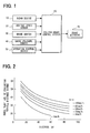
- Fig. 1 shows a block diagram showing a structure of a brake control system for a vehicle.
- the brake control system has a radar device 10, a vehicle speed sensor 20, a brake switch 30, a brake pressure sensor 40, an operation control switch 50, an electronic control unit (ECU) 60 for the brake control system, and a brake actuator 70.
- ECU electronice control unit
- the radar device 10 emits radar beams to a predetermined area in front of a driver's vehicle and receives reflected radar beams in order to detect a vehicle distance "D" between the driver's vehicle and a front obstacle (e.g. a front vehicle) as well as a relative position of the front obstacle with respect to the driver's vehicle.
- a relative vehicle speed "Vr" can be calculated by differentiating the vehicle distance "D" (detected by the radar device 10) by time.
- a minus sign (-) is given to the relative vehicle speed "Vr" when the driver's vehicle is approaching closer to the front vehicle
- a plus sign (+) is given to the relative vehicle speed "Vr” when the driver's vehicle is moving away from the front vehicle.
- the vehicle speed sensor 20 detects a vehicle running speed of the driver's vehicle.
- a running speed of the front obstacle i.e. a vehicle running speed of the front vehicle
- a difference between the relative vehicle speed "Vr” and the vehicle running speed of the driver's vehicle can be obtained by a difference between the relative vehicle speed "Vr" and the vehicle running speed of the driver's vehicle.
- the brake switch 30 detects a braking operation carried out by the vehicle driver to output an "ON" signal when a brake pedal is depressed (operated), or to output an "OFF” signal when the depressing stroke for the brake pedal is released.
- the brake pressure sensor 40 detects pressure of brake fluid generated in a braking device (not shown), when the brake pedal is depressed by the vehicle driver. Then, a brake pad is pressed against a disc rotor fixed to a vehicle wheel at such a pressure corresponding to the pressure of the brake fluid, so that a braking force is generated to decelerate the vehicle. Therefore, a deceleration generated in the vehicle by the depression of the brake pedal can be presumed based on the pressure of the brake fluid produced by the pedal operation of the vehicle driver.
- the operation control switch 50 is operated by the vehicle driver and its operation signal is inputted into the ECU 60 for the brake control system.
- the operation control switch 50 gives an instruction to the ECU 60 when the ECU 60 carries out a brake assisting control to the braking operation by the vehicle driver, so that a vehicle deceleration is controlled, for example, the vehicle is slowly or rapidly decelerated.
- the brake actuator 70 regulates the pressure of the brake fluid in the braking device at a desired value in accordance with a command signal from the ECU 60.
- the ECU 60 carries out the brake assisting control to the braking force generated by the braking device, based on inputted signals from the above various switches and sensors, when the vehicle driver operates the brake pedal in the case that the driver's vehicle is approaching closer to the front obstacle.
- the above brake assisting control is carried out such that a collision against the front obstacle is avoided and a comfortable feeling for the vehicle deceleration is obtained.
- the brake assisting control is carried out by use of an index "KdB" of evaluating a vehicle distance change, which is an index for indicating a condition of a vehicle distance between the driver's vehicle and the front obstacle (vehicle). Accordingly, the index "KdB" of evaluating the vehicle distance change will be explained at first.
- the vehicle driver assesses whether the driver's vehicle is approaching closer to the front vehicle or whether the driver's vehicle is moving away from the front vehicle, based on a visual change of dimensions of the front vehicle. Then, the vehicle driver controls the vehicle acceleration or deceleration by the operation of an acceleration pedal or the brake pedal. Accordingly, the index "KdB" of evaluating the vehicle distance change is calculated as an index for indicating the visual change of dimensions of the front vehicle. Therefore, the visual change of dimensions of the front vehicle, which is a criterion of judgment for the vehicle driver, is calculated as the index "KdB" for evaluating the vehicle distance change.
- a visual area "S” (visual dimensions) of the front vehicle can be calculated by the following formula 1; wherein
- the time-rate-of-change "dS/dt" for the visual area "S" of the front vehicle can be indicated by the following formula 3, wherein a partial differentiation is performed in the above formula 2 with respect to the distance "D". And this is defined as a time-rate-of-change "K" for the area "S" of the front vehicle.
- the time-rate-of-change "K" for the area "S" of the front vehicle can be calculated based on the vehicle distance "D" between the driver's vehicle and the front vehicle and the relative vehicle speed "Vr", which is a time-rate-of-change of the vehicle distance "D".
- the time-rate-of-change "K" for the area "S" of the front vehicle also indicates the time-rate-of-change "dS/dt" for the visual area "S" of the front vehicle. Therefore, the time-rate-of-change "K” is equal to a time-rate-of-change for the image of the front vehicle (for example, photographed by a camera) for a unit time. Accordingly, the time-rate-of-change "K” for the area "S" of the front vehicle can be alternatively calculated in the following manner, in which an imaging device (such as the camera) is installed in the vehicle and the time-rate-of-change "K” is calculated from the time-rate-of-change for the image of the front vehicle for the unit time.
- an imaging device such as the camera
- the time-rate-of-change "K" for the area "S" of the front vehicle largely changes in a unit of 10 6 , when the vehicle distance is between 1 and 100 m. Therefore, the time-rate-of-change "K” is indicated in dB.
- time-rate-of-change "K 0 " is a minimum area change which the vehicle driver can recognize as an area change.
- the value for the time-rate-of-change "K 0 " of the above situation is "0[dB]”.
- the time-rate-of-change "K 0 " can be calculated by the following formula 4.
- an index calculated by the following formula 5 is defined as the index "KdB” of evaluating the vehicle distance change.
- the value of "KdB” is a positive figure when the driver's vehicle is approaching closer to the front vehicle, whereas the value of "KdB” is a negative figure when the driver's vehicle is moving away from the front vehicle.
- Fig. 2 shows the index "KdB” of evaluating the vehicle distance change, which is defined by the formula 5 and which varies depending on the vehicle distance “D” and the relative vehicle speed “Vr” between the driver's vehicle and the front vehicle.
- the index "KdB” of evaluating the vehicle distance change becomes larger as the relative vehicle speed "Vr" approaching closer to the front vehicle is higher, and an increasing gradient in each relative vehicle speed becomes larger as the vehicle distance "D" is shorter.
- the brake assisting control to the braking force to be carried out by the ECU 60 will be explained with reference to the flow chart shown in Fig. 3 .
- the ECU 60 reads, at a step S100, input signals from the various sensors and switches 10 to 50.
- the ECU 60 determines at a step S110 whether the detected signal from the brake switch 30 is changed from the "OFF" signal to the "ON” signal. Namely, the ECU 60 determines at the step S110 whether the vehicle driver started the operation of the brake pedal.
- the process goes to a step S120.
- a current value "KdB_p" for the index "KdB” of evaluating the vehicle distance change is calculated at the step S120. Namely, the current value "KdB_p” is calculated by substituting the values "D" and “Vr" in the above formula 5 with the vehicle distance "D” detected by the radar device 10 and the relative vehicle speed "Vr", which is the time-rate-of-change of the vehicle distance "D".
- the ECU 60 calculates a target value "KdB_t" for the index "KdB” of evaluating the vehicle distance change.
- a method for calculating the target value "KdB_t” will be explained with reference to Fig. 4 .
- the current value "KdB_p" calculated at the step S120 is set as an initial value "KdB0".
- a gradient "a" of the index "KdB” of evaluating the vehicle distance change is calculated by differentiating the above current value "KdB_p" with respect to the distance "D".
- the target value "KdB_t" for the index "KdB” of evaluating the vehicle distance change can be calculated by the following formula 6, namely based on the initial value “KdB 0 ", the gradient “a”, the vehicle distance “D 0 " at the time point of starting the vehicle deceleration, a "gain” which is changed by the operation control signal from the operation control switch 50, and the current vehicle distance "D p " between the driver's vehicle and the front vehicle.
- KdB_t gain ⁇ a ⁇ Dp + a ⁇ D 0 + KdB 0
- the target value "KdB_t" for the index "KdB” of evaluating the vehicle distance change can be obtained as such a straight line, as shown in Fig. 4 , wherein the straight line crosses the initial value “KdB 0 " and the index "KdB” is increased with a constant gradient "a” from the initial value "KdB 0 " as the vehicle distance "D p " is decreased.
- the target value "KdB_t" at the current vehicle distance "D p " can be calculated by substituting the current vehicle distance "D p " into the above formula 6.
- a value for the "gain", which is changed by the operation control signal from the operation control switch 50, is selected from a group, for example, "0.9", “1.0” and "1.1".
- the deceleration of the vehicle can be controlled in the brake assisting control to the braking operation, by changing the gradient "a" which is multiplied by the "gain” selected by the vehicle driver. Accordingly, the decelerating operation of the vehicle can be adjusted depending on the preference of the vehicle driver.
- a target value "Vr_t" of the relative vehicle speed is calculated by the following formula 7, wherein the target value "KdB_t" calculated in the step S130 is used.
- Vr_t - 1 / 2 ⁇ 10 KdB_t / 10 ⁇ D 3 ⁇ 5 ⁇ 10 - 8
- a curved line is supposed, as shown in Fig. 4 , wherein the curved line crosses the initial value "KdB 0 " and a current value "KdB_p" for the index "KdB” of evaluating the vehicle distance change at the current value "Dp” of the vehicle distance.
- the target value "Vr_t" of the relative vehicle speed is calculated from the curved line supposed as above.
- a target value "dVr/dt_t” for a relative vehicle deceleration is calculated by the following formula 8, wherein the current value "Vr_p" of the relative vehicle speed "Vr” and the target value “Vr_t” of the relative vehicle speed are substituted.
- the current value "Vr_p” of the relative vehicle speed is calculated by performing the differentiation of the current value "Dp" of the vehicle distance between the driver's vehicle and the front vehicle.
- dVr / dt_t Vr_p - Vr_t / ⁇ t
- ⁇ t is a divisor for converting a difference between the current value "Vr_p” and the target value "Vr_t” of the relative vehicle speed into the target value "dVr/dt_t” for the relative vehicle deceleration.
- the value for ⁇ t is appropriately selected.
- the ECU 60 determines whether a collision tolerable time "TTC" is shorter than a predetermined time "Tref", wherein the collision tolerable time “TTC” is a remaining time until the driver's vehicle may possibly crash against the front vehicle. In the case that the collision tolerable time “TTC” is shorter than the predetermined time “Tref”, the process goes on to a step S170. On the other hand, when the collision tolerable time "TTC" is longer than the predetermined time "Tref", the process goes to a step S200.
- the collision tolerable time "TTC” is longer than the predetermined time "Tref"
- a vehicle relative deceleration "dVr/dt_dr" of the driver's own vehicle is presumed based on the braking pressure generated by the driver's operation of the brake pedal.
- the ECU 60 determines whether the presumed value "dVr/dt_dr" for the vehicle relative deceleration (which corresponds to the driver's braking operation) is larger than a target value "dVr/dt_t” for the vehicle relative deceleration.
- the vehicle deceleration is indicated by a negative figure.
- the process goes to a step S190 to carry out the brake assisting control to the braking operation.
- the brake assisting control to the braking operation is carried out when the collision tolerable time "TTC" (during which the vehicle may not crash against the front vehicle) is shorter than the predetermined time "Tref” and it is not possible to decelerate the vehicle at the target value "dVr/dt_t” for the vehicle relative deceleration by the braking operation of the vehicle driver.
- a braking pressure for generating the target value "dVr/dt_t" of the vehicle relative deceleration (which is calculated at the step S150) is obtained from a map prepared in advance, so that the brake actuator 70 is so controlled to generate such braking pressure.
- an actual deceleration of the vehicle may be detected to operate the brake actuator 70 to control the braking pressure, such that the actual deceleration meets the target value "dVr/dt_t" of the vehicle relative deceleration.
- the ECU 60 determines at the step S180, that the presumed value "dVr/dt_dr" for the vehicle relative deceleration (which corresponds to the driver's braking operation) is smaller than the target value "dVr/dt_t” for the vehicle relative deceleration, it is possible to decelerate the vehicle by the driver's braking operation at such a deceleration which is higher than the target value "dVr/dt_t" of the vehicle relative deceleration. It is, therefore, not necessary to perform the brake assisting control to the braking operation, because the sufficient deceleration can be achieved simply by the driver's braking operation. Accordingly, the process goes to the step S200, at which no brake assisting control is carried out to the braking operation.
- the ECU 60 determines whether a condition for terminating the brake assisting control to the braking operation is satisfied or not.
- the condition for terminating the process is satisfied, for example, when the driver's vehicle has stopped, when the collision tolerable time "TTC" becomes longer than the predetermined time “Tref” as a result that the front vehicle has accelerated, or when the index "KdB" of evaluating the vehicle distance change is decreased to become lower than the target value "KdB_t" by a predetermined amount.
- the process is repeatedly carried out from the step S100.
- the brake assisting control is carried out to the braking operation in the above brake control system of the first embodiment.
- the index "KdB” of evaluating the vehicle distance change has a characteristic feature that the increasing gradient becomes larger as the vehicle distance "D" to the front vehicle is shorter. Accordingly, when the target value "KdB_t" for the index "KdB” of evaluating the vehicle distance change is calculated, wherein the increasing gradient is constant, the decreasing ratio of the relative vehicle speed "Vr" to the front vehicle is made larger as the vehicle distance "D" to the front vehicle becomes shorter.
- the vehicle driver gets a comfortable feeling for the deceleration in the braking operation. It has been confirmed through experiments that the vehicle driver having a high skill in driving the vehicle performs the braking operation in the following manner.
- the increasing gradient of the index "KdB" of evaluating the vehicle distance change is maintained by the vehicle driver at such a value which is the value when the braking operation has started, so that an appropriate vehicle distance to the front vehicle is maintained.
- the increasing gradient "a”, which is used for calculating the target value "KdB_t” for the index “KdB” of evaluating the vehicle distance change, varies depending on the vehicle distance "D 0 " to the front vehicle when the braking operation starts.
- the target value "KdB_t” for the index “KdB” of evaluating the vehicle distance change is appropriately calculated depending the vehicle distance "D” to the front vehicle and the relative vehicle speed "Vr", so that the vehicle is decelerated to avoid the crash against the front vehicle.
- the collision tolerable time “TTC” is compared with the predetermined time “Tref”, and the brake assisting control is carried out when the collision tolerable time “TTC” is shorter than the predetermined time “Tref".
- the predetermined time “Tref” may be changed depending on a vehicle speed "Vb" of the front vehicle, as shown in Fig. 5 . Namely, the predetermined time “Tref” is made longer as the vehicle speed "Vb" of the front vehicle is higher. According to such a modification, an appropriate braking force is generated in the braking operation of the present invention, even when the front vehicle is rapidly decelerated.
- a level (a value) of the "Tref" for starting the brake assisting control is made different from a level (a value) of the "Tref” for terminating the brake assisting control, in the case that the value for the "Tref” is changed depending on the change of the vehicle speed "Vb" of the front vehicle. This is to prevent the determination of the ECU from repeatedly changing from “YES” to “NO”, or vice versa, at the step S160, depending on the change of the vehicle speed "Vb" of the front vehicle.
- the current value "KdB_p" for the index "KdB” of evaluating the vehicle distance change is calculated at the step S120, when the detected signal from the brake switch 30 is changed from “OFF” to "ON” at the step S110, namely when the vehicle driver starts the braking operation.
- the braking operation by depressing the brake pedal there are other operations performed by the vehicle driver for decelerating the vehicle, for example, an acceleration-pedal-off operation in which a pedal stroke for depressing an acceleration pedal is decreased, an operation for a gear shift in which a position of a shift lever is changed so that an engine brake is generated, and so on.
- the ECU may determine at the step S110 of Fig. 3 whether or not any operation for decelerating the vehicle has been started, based on the detection for the acceleration-pedal-off operation or the gear shift operation, other than the braking operation by the brake pedal.
- the vehicle deceleration which will be caused by the acceleration-pedal-off operation or the gear shift operation, may be presumed at the step S170 of Fig. 3 based on the vehicle speed, the shit position (a speed reduction ratio of a transmission), and so on.
- the target value "KdB_t” for the index "KdB” of evaluating the vehicle distance change is calculated and set when the vehicle driver starts the braking operation.
- the target value "dVr/dt_t” for the relative vehicle deceleration is calculated based on the the target value "Vr_t” of the relative vehicle speed "Vr” obtained from the above target value "KdB_t” and based on the current value "Vr_p" of the relative vehicle speed "Vr”.
- the brake assisting control is carried out such that the actual vehicle deceleration is controlled at the target value "dVr/dt_t" for the relative vehicle deceleration.
- a second embodiment differs from the first embodiment in the following points.
- a deceleration target is calculated based on the normal deceleration of the vehicle, the vehicle distance between the driver's vehicle and the front vehicle, and the actual relative vehicle speed.
- the deceleration target is an index indicating a starting point (a starting timing) for carrying out a control operation to the braking force of the brake control device.
- the target value "KdB_t" for the index "KdB” of evaluating the vehicle distance change is calculated and set when the current value "KdB_p" becomes higher than the deceleration target.
- the brake assisting control to the braking force is started only after the braking operation has been carried out by the vehicle driver.
- the control operation to the braking force in other words, a braking operation can be performed when a certain condition is satisfied, whether or not the braking operation has been actually carried out by the vehicle driver.
- the ECU 60 reads, at a step 5300, input signals from the various sensors and switches 10 to 50.
- the current value "KdB_p" for the index "KdB” of evaluating the vehicle distance change is calculated at a step S310. Namely, as in the same manner to the first embodiment, the current value "KdB_p" is calculated by substituting the values "D" and "Vr" in the above formula 5 with the vehicle distance "D” detected by the radar device 10 and the relative vehicle speed "Vr", which is the time-rate-of-change of the vehicle distance "D".
- the ECU 60 calculates the deceleration target "KdB_ssdc", which is the index indicating the timing for carrying out the control operation to the braking force of the brake control device, based on the normal deceleration "nd" of the vehicle, the vehicle distance “D” between the driver's vehicle and the front vehicle, and the actual relative vehicle speed "Vr".
- KdB_ssdc log
- nd represents the normal deceleration of the vehicle generated by the normal braking operation carried by the vehicle driver.
- a deceleration generated in the vehicle by the engine brake may be used in place of "nd".
- the ECU 60 determines whether the current value "KdB_p" for the index "KdB” of evaluating the vehicle distance change is larger than the deceleration target "KdB_ssdc". In the case that the current value "KdB_p" is larger than the deceleration target "KdB_ssdc", the process goes to a step S340 in order to start the control operation for the braking force. On the other hand, when the current value "KdB_p" is smaller than the deceleration target "KdB_ssdc", the process goes to a step S300 to repeat the above steps S300 to S330.
- the deceleration target "KdB_ssdc" is calculated based on the normal deceleration "nd" of the vehicle, and the control operation to the braking force is started when the current value "KdB_p" of the index "KdB” becomes larger than the deceleration target "KdB_ssdc".
- the control operation to the braking force can be started at such a timing, at which the vehicle driver would usually start any operation for decelerating the vehicle speed, even in the case the vehicle driver does not actually start the operation for the vehicle deceleration.
- the target value "KdB_t" for the index "KdB” of evaluating the vehicle distance change is calculated.
- the method for calculating the target value "KdB_t” is the same to that in the first embodiment, which is explained with reference to Fig. 4 . Namely, according to the step S340, the target value "KdB_t" for the index “KdB” of evaluating the vehicle distance change is set such that the target value "KdB_t" is increased with a constant gradient as the distance to the front vehicle becomes shorter. Accordingly, the vehicle can be decelerated in such a manner that the decreasing ratio of the relative vehicle speed "Vr" to the front vehicle is made larger as the vehicle distance "D" to the front vehicle becomes shorter. As a result, the vehicle driver gets a comfortable decelerating feeling.
- the target value "Vr_t" of the relative vehicle speed is calculated by the following formula 15, wherein the target value "KdB_t" calculated in the step S340 is used.
- Vr_t - 1 / 2 ⁇ 10 KdB_t / 10 ⁇ D 3 ⁇ 5 ⁇ 10 - 8
- the curved line is supposed, as shown in Fig. 4 , wherein the curved line crosses the initial value "KdB 0 " and the current value "KdB_p" for the index "KdB” of evaluating the vehicle distance change at the current value "Dp" of the vehicle distance.
- the target value "Vr_t" of the relative vehicle speed is calculated from the curved line supposed as above.
- the target value "dVr/dt_t” for the relative vehicle deceleration is calculated by the following formula 16, wherein the current value "Vr_p" of the relative vehicle speed "Vr” and the target value "Vr_t” of the relative vehicle speed are substituted.
- ⁇ t is a divisor for converting a difference between the current value "Vr_p” and the target value "Vr_t” of the relative vehicle speed into the target value "dVr/dt_t” for the relative vehicle deceleration.
- the value for At is appropriately selected.
- the ECU 60 determines whether the collision tolerable time "TTC" is shorter than the predetermined time "Tref", wherein the collision tolerable time “TTC” is the remaining time until the driver's vehicle may possibly crash against the front vehicle. In the case that the collision tolerable time “TTC” is shorter than the predetermined time “Tref”, the process goes on to a step S380. On the other hand, when the collision tolerable time “TTC” is longer than the predetermined time "Tref", the process goes to a step S390.
- the control operation to the braking operation is carried out. Namely, the control operation to the braking operation is carried out, when the collision tolerable time "TTC" (during which the vehicle may not crash against the front vehicle) is shorter than the predetermined time “Tref” and it is not possible to decelerate the vehicle at the target value "dVr/dt_t" for the vehicle relative deceleration by the braking operation of the vehicle driver.
- TTC collision tolerable time
- Tref the predetermined time
- the braking pressure for generating the target value "dVr/dt_t" of the vehicle relative deceleration (which is calculated at the step S360) is obtained from a map prepared in advance, so that the brake actuator 70 is so controlled to generate such braking pressure.
- an actual deceleration of the vehicle may be detected to operate the brake actuator 70 to control the braking pressure, such that the actual deceleration meets the target value "dvr/dt_t" of the vehicle relative deceleration.
- the ECU 60 determines whether a condition for terminating the control operation to the braking force is satisfied or not.
- the condition for terminating the process is satisfied, for example, when the driver's vehicle has stopped, when the collision tolerable time "TTC" becomes longer than the predetermined time “Tref” as a result that the front vehicle has accelerated, or when the current value "KdB_p" for the index "KdB” of evaluating the vehicle distance change is decreased to become lower than the target value "KdB_t" by a predetermined amount.
- the process is repeatedly carried out from the step S300.
- the above explained control operation to the braking force is carried out. Namely, in the case that the vehicle is approaching closer to the front vehicle, the control operation to the braking force can be started at such a timing, at which the vehicle driver would usually start any operation for decelerating the vehicle speed, even if the vehicle driver would not actually start the operation for the vehicle deceleration.
- the target value "KdB_t" for the index "KdB” of evaluating the vehicle distance change is set such that the target value "KdB_t” is increased with a constant gradient as the distance to the front vehicle becomes shorter. Accordingly, the vehicle can be decelerated in such a manner that the decreasing ratio of the relative vehicle speed "Vr" to the front vehicle is made larger as the vehicle distance "D" to the front vehicle becomes shorter. As a result, the vehicle driver gets a comfortable decelerating feeling.
- the current value "KdB_p" for the index "KdB” of evaluating the vehicle distance change is calculated based on the vehicle distance "D" to the front vehicle and the relative vehicle speed "Vr", which is the time-rate-of-change of the vehicle distance "D".
- Vr the relative vehicle speed
- a vehicle speed "Vb" of the front vehicle is not taken into consideration for calculating the above current value "KdB_p”.
- the timing for starting the control operation to the braking force may not match a degree of risk, which the vehicle driver feels.
- Fig. 7 shows the index "KdB" of evaluating the vehicle distance change at the timing of starting the braking operation by the vehicle driver, in the case that the driver's vehicle is approaching closer to the front vehicle, and the distance "D" to the front vehicle at such timing (starting the braking operation).
- Vr the relative vehicle speed
- D the distance
- the vehicle driver feels a higher risk in the case that the driver's vehicle is approaching closer to the front vehicle as a result of the vehicle deceleration of the front vehicle, than in the case in which the driver's vehicle is likewise approaching closer to the front vehicle as a result of the vehicle acceleration of the driver's vehicle, even if the relative vehicle speed to the front vehicle is the same in each of the cases. Accordingly, it is preferable to start the control operation to the braking force (i.e. the operation of the vehicle deceleration) at an earlier timing, when the vehicle is approaching closer to the front vehicle and the vehicle driver feels a higher risk.
- the braking force i.e. the operation of the vehicle deceleration
- the index "KdB" of evaluating the vehicle distance change is calculated based on the vehicle distance "D" to the front vehicle and the relative vehicle speed "Vr". Therefore, the vehicle deceleration is started at the same timing, even in the case that the vehicle driver feels a higher risk. As a result, the timing for starting the control operation to the braking force (the vehicle deceleration) may not match the degree of risk, which the vehicle driver feels.
- a corrected value "KdB_c" for the index "KdB” of evaluating the vehicle distance change is used, wherein the vehicle speed "Vb" of the front vehicle is taken into consideration, as indicated in the following formula 17.
- ⁇ is a coefficient smaller than 1.0, and it is confirmed that 0.3 is most appropriate for the value of ⁇ .
- KdB_C 10 ⁇ log - 2 ⁇ Vr + ⁇ ⁇ Vb / D 3 ⁇ 5 ⁇ 10 - 8
- Fig. 8 shows the corrected value "KdB_c" for the index "KdB” of evaluating the vehicle distance change and the vehicle distance "D" to the front vehicle at the timing of starting the braking operation, wherein the corrected values "KdB_c" are obtained from experiments in which a vehicle test driver was instructed to start the braking operation as late as possible but to avoid the crash against the front vehicle.
- the timings for starting the braking operation are distributed on a certain curved line, when the corrected value "KdB_c" (calculated by the formula 17) is used.
- An approximate expression of the curved line can be expressed by the following formula 18, and the formula 18 has a characteristic feature shown in Fig. 9 .
- KdB_C - 23.76 ⁇ logD + 76.96
- Fig. 10 shows a distribution of differences between the formula 18, which is obtained from the starting points of the braking operation by the test driver, and the corrected value "KdB_c" at the actual starting time of the braking operation.
- the vehicle test driver was instructed to start the braking operation as late as possible, while he should avoid the crash against the front vehicle.
- the differences are distributed in a small range (A distribution curve has a sharp peak). Therefore, the approximate expression of the formula 18 is considered as being possible to use as a threshold value for determining the starting timing of the braking operation.
- Fig. 11 shows a distribution (indicated by a dotted line) of differences between the approximate expression of the formula 18 and the corrected values "KdB_c" at the starting timings of the braking operation in the normal running of the vehicle.
- Fig. 11 further shows a distribution (indicated by a solid line) of differences between the approximate expression of the formula 18 and the corrected values "KdB_c" at such timings at which the vehicle driver recognized the risk. Those timings are collected and obtained from accident data for the rear end collisions.
- the control operation to the braking operation will be started at a timing of such a range out of the normal starting timings for the braking operation, in the case that the brake control operation for suppressing the rear end collisions is carried out at such timings which are decided based on the threshold values obtained from the approximate expression of the formula 18.
- the formula 18 is obtained from the starting points of the braking operations in the experiments by the vehicle test driver. Accordingly, the starting point (timing) of the control operation to the braking operation does not come into the range for the rear end collisions.
- the ECU 60 reads the input signals from the various sensors and switches 10 to 50.
- the ECU 60 calculates a current value for the corrected value "KdB_c".
- the current value "KdB_c" for the corrected value "KdB_c” is calculated by substituting the vehicle distance "D" to the front vehicle, which is detected by the radar device 10, into the formula 18.
- the ECU 60 calculates the deceleration target "KdB_ssdc", which is the index indicating the timing for carrying out the control operation to the braking force of the brake control device, based on the normal deceleration "nd" of the vehicle, the vehicle distance “D” between the driver's vehicle and the front vehicle, and the actual relative vehicle speed "Vr".
- the ECU 60 determines whether the current value "KdB_c" of the corrected value "KdB_c" for the index "KdB” of evaluating the vehicle distance change is larger than the deceleration target "KdB_ssdc". In the case that the current value "KdB_c" is larger than the deceleration target "KdB_ssdc", the process goes to a step S340a in order to start the control operation for the braking force. On the other hand, when the current value "KdB_c" is smaller than the deceleration target "KdB_ssdc", the process goes back to the step S300 to repeat the above steps S300 to S330a.
- a target value "KdB_c_t" of the corrected value "KdB_c” for the index "KdB” of evaluating the vehicle distance change is calculated.
- the method for calculating the target value "KdB_c_t” is the same to that in the first embodiment, which is explained with reference to Fig. 4 . Namely, according to the step S340a, the target value "KdB_c_t" of the corrected value "KdB_c” is set such that the target value "KdB_c_t” is increased with a constant gradient as the distance to the front vehicle becomes shorter. Accordingly, the vehicle can be decelerated in such a manner that the decreasing ratio of the relative vehicle speed "Vr" to the front vehicle is made larger as the vehicle distance "D" to the front vehicle becomes shorter.
- the target value "Vr_t” of the relative vehicle speed is calculated by the following formula 19, wherein the target value "KdB_c_t” calculated in the step S340a is used.
- Vr_t - 1 / 2 ⁇ 10 KdB_c_t / 10 ⁇ D 3 ⁇ 5 ⁇ 10 - 8
- the target value "dVr/dt_t” for the relative vehicle deceleration is calculated by the following formula 20, wherein the current value "Vr_p" of the relative vehicle speed "Vr” and the target value "Vr_t” of the relative vehicle speed are substituted.
- the ECU 60 determines whether the collision tolerable time "TTC" is shorter than the predetermined time "Tref", wherein the collision tolerable time “TTC” is the remaining time until the driver's vehicle may possibly crash against the front vehicle. In the case that the collision tolerable time “TTC” is shorter than the predetermined time “Tref”, the process goes on to the step S380. On the other hand, when the collision tolerable time “TTC” is longer than the predetermined time "Tref", the process goes to the step S390.
- the control operation to the braking operation is carried out. Namely, the control operation to the braking operation is carried out, when the collision tolerable time "TTC" (during which the vehicle may not crash against the front vehicle) is shorter than the predetermined time “Tref” and it is not possible to decelerate the vehicle at the target value "dVr/dt_t" for the vehicle relative deceleration.
- TTC collision tolerable time
- Tref the predetermined time
- the ECU 60 determines whether the condition for terminating the control operation to the braking force is satisfied or not.
- the condition for terminating the process is satisfied, for example, when the driver's vehicle has stopped, when the collision tolerable time "TTC" becomes longer than the predetermined time “Tref” as a result that the front vehicle has accelerated, or when the current value "KdB_c" for the index "KdB” of evaluating the vehicle distance change is decreased to become lower than the target value "KdB_c_t" by a predetermined amount.
- the process is repeatedly carried out from the step S300.
- the brake control operation is carried out at such timings which are decided based on the threshold values obtained from the approximate expression of the formula 18 (which is obtained from the starting points of the braking operation by the test driver), and the relative vehicle deceleration to the front vehicle is controlled at a target relative deceleration "dVr/dt_ssdc" during the decelerating operation.
- An operation of the braking control according to the fourth modification, which is performed by the ECU 60, will be explained with reference to the flowchart shown in Fig. 13 .
- the ECU 60 reads the input signals from the various sensors and switches 10 to 50.
- the ECU 60 calculates a current value for the corrected value "KdB_c".
- the ECU 60 calculates a threshold value "KdB_s" for the corrected value "KdB_c" of the index "KdB” of evaluating the vehicle distance change, based on the approximate expression of the formula 18, which is obtained from the starting points of the braking operation by the test driver.
- a step S440 the ECU 60 determines whether the current value "KdB_c" of the corrected value "KdB_c" for the index "KdB” of evaluating the vehicle distance change is larger than the threshold value "KdB_s". In case of "YES” at the step S440, the process goes to a step S450, whereas in case of "No” at the step S440, the process goes back to the step S410 to repeat the above steps.
- the control operation to the braking operation is carried out.
- the ECU calculates the target relative deceleration "dVr/dt_ssdc", based on the vehicle distance "D", the relative vehicle speed "Vr”, and the current value "KdB_c" of the corrected value "KdB_c”.
- the relative vehicle deceleration to the front vehicle is controlled at the target relative deceleration "dVr/dt_ssdc".
- the target relative deceleration "dVr/dt_ssdc” can be calculated by the following formula 21, which is a formula for differentiating the formula 17 by time.
- the target relative deceleration "dVr/dt_ssdc" indicated by the above formula 21 expresses a target value of the relative vehicle deceleration for keeping the current distance "D" to the front vehicle. Accordingly, it becomes possible to keep the current value "KdB_c" of the corrected value "KdB_c" (in other words, to keep the current vehicle distance "D"), when the vehicle is decelerated to achieve the target relative deceleration "dVr/dt_ssdc".
- the target relative deceleration "dVr/dt_ssdc” is multiplied by a first gain "gain 1", which is a positive figure less than 1.0.
- a target relative vehicle speed "Vr_da” may be taken into consideration when the target relative deceleration "dVr/dt_ssdc” may be calculated.
- the current value "KdB_c" of the corrected value "KdB_c" can be kept.
- the vehicle deceleration is carried out to achieve the target relative deceleration "dVr/dt_ssdc", under the above situation ("Vr_da” > 0)
- the vehicle can be decelerated that the relative vehicle speed is decreased from the current relative vehicle speed "Vr” to the target relative vehicle speed "Vr_da".
- the target relative deceleration "dVr/dt_ssdc" is multiplied by a second gain "gain 2", which is a positive figure less than 1.0 and which is decided by the vehicle speed of the front vehicle. Namely, the degree of risk for the vehicle becomes higher as the vehicle speed of the front vehicle is higher, in particular when the front vehicle is rapidly decelerated. It is tendency that the vehicle driver decelerates the vehicle with a higher deceleration, as the vehicle speed of the front vehicle is higher.
- dVr/dt_ssdc gain ⁇ 2 ⁇ gain ⁇ 1 ⁇ 7.5 ⁇ D 2 ⁇ 10 KdB_p / 10 - 8 ⁇ Vr - Vr_da
- the figure for the second gain "gain 2" may be selected, for example, as 0.5 in case of the vehicle speed of the front vehicle being less than 50 km/h ("Vb" ⁇ 50 km/h), and 1.0 in case of the vehicle speed of the front vehicle being higher than 50 km/h ("Vb" > 50 km/h). Then, it becomes possible to make the target relative deceleration "dVrdt_ssdc" to match the deceleration generated by the braking operation carried out by the vehicle driver.
- the ECU 60 determines whether a condition for terminating the control operation to the braking force is satisfied or not.
- the condition for terminating the process is satisfied, for example, when the driver's vehicle has stopped, or when the current value "KdB_c" for the corrected value "KdB_c" of the index "KdB” of evaluating the vehicle distance change becomes lower than the threshold value "KdB_s".
- the process is repeatedly carried out from the step S410.
- the control operation for decelerating the vehicle is started when the corrected value "KdB_c" of the index "KdB” of evaluating the vehicle distance change becomes larger than the threshold value "KdB_s".
- the degree of risk which the vehicle driver feels.
- the target value "dVr/dt_t” for the relative vehicle deceleration is calculated by the formula 20 (at the step S360 of Fig. 12 ), wherein the current value "Vr_p" of the relative vehicle speed "Vr” and the target value “Vr_t” of the relative vehicle speed are substituted.
- the target value "Vr_t” of the relative vehicle speed is calculated by the formula 19 (at the step S350 of Fig. 12 ), wherein the target value "KdB_c_t" for the corrected value "KdB_c” of evaluating the vehicle distance change is used.
- the above target value "KdB_c_t" for the corrected value "KdB_c” of evaluating the vehicle distance change is alternatively calculated in the following manner.
- the steps S410 to S440 of Fig. 13 are the same for the fifth modification.
- the ECU determines that the current value "KdB_c" for evaluating the vehicle distance change is larger than the threshold value "KdB_s".
- a tangent line (a dotted line in Fig. 14 ) is obtained, which is a tangent line of the approximate expression for the corrected index "KdB_c" of evaluating the vehicle distance change at such a timing, at which the current value "KdB_c" (calculated by the formula 17) for evaluating the vehicle distance change is determined as being larger than the threshold value "KdB_s" (calculated by the formula 18), that is at the timing at which the braking operation has been started.
- the above tangent line is used as the target value "KdB_c_t" for the corrected value "KdB_c” of evaluating the vehicle distance change.
- the timing for starting the control operation to the braking force may match a degree of risk, which the vehicle driver feels.
- the above target value "KdB_c_t" for the corrected value "KdB_c” of evaluating the vehicle distance change may be alternatively calculated in the following manner, as in the sixth modification shown in Fig. 15 .
- the steps S410 to S440 of Fig. 13 are also the same for the sixth modification.
- the ECU determines that the current value "KdB_c" (calculated by the formula 17) for evaluating the vehicle distance change is larger than the threshold value "KdB_s" (calculated by the formula 18).
- each value (indicated by a dotted line in Fig. 15 ) of the approximate expression for the corrected index "KdB_c" of evaluating the vehicle distance may be used as the target value "KdB_c_t" for the corrected value "KdB_c" of evaluating the vehicle distance change.
- the timing for starting the control operation to the braking force may match a degree of risk, which the vehicle driver feels.
Landscapes
- Engineering & Computer Science (AREA)
- Transportation (AREA)
- Mechanical Engineering (AREA)
- Regulating Braking Force (AREA)
Applications Claiming Priority (4)
| Application Number | Priority Date | Filing Date | Title |
|---|---|---|---|
| JP2006143207 | 2006-05-23 | ||
| JP2006228373 | 2006-08-24 | ||
| JP2007007473A JP4645598B2 (ja) | 2006-05-23 | 2007-01-16 | 車両用ブレーキ制御装置 |
| EP07010165A EP1860007B1 (de) | 2006-05-23 | 2007-05-22 | Bremssteuersystem für Fahrzeuge |
Related Parent Applications (1)
| Application Number | Title | Priority Date | Filing Date |
|---|---|---|---|
| EP07010165.4 Division | 2007-05-22 |
Publications (2)
| Publication Number | Publication Date |
|---|---|
| EP2256010A1 true EP2256010A1 (de) | 2010-12-01 |
| EP2256010B1 EP2256010B1 (de) | 2012-03-14 |
Family
ID=38432871
Family Applications (2)
| Application Number | Title | Priority Date | Filing Date |
|---|---|---|---|
| EP10176757A Expired - Fee Related EP2256010B1 (de) | 2006-05-23 | 2007-05-22 | Bremssteuersystem für Fahrzeug |
| EP07010165A Expired - Fee Related EP1860007B1 (de) | 2006-05-23 | 2007-05-22 | Bremssteuersystem für Fahrzeuge |
Family Applications After (1)
| Application Number | Title | Priority Date | Filing Date |
|---|---|---|---|
| EP07010165A Expired - Fee Related EP1860007B1 (de) | 2006-05-23 | 2007-05-22 | Bremssteuersystem für Fahrzeuge |
Country Status (4)
| Country | Link |
|---|---|
| US (1) | US7395144B2 (de) |
| EP (2) | EP2256010B1 (de) |
| JP (1) | JP4645598B2 (de) |
| DE (1) | DE602007013965D1 (de) |
Cited By (1)
| Publication number | Priority date | Publication date | Assignee | Title |
|---|---|---|---|---|
| DE102011113098B4 (de) | 2011-09-09 | 2024-02-01 | Volkswagen Aktiengesellschaft | Verfahren und Vorrichtung zur Folgenminderung einer Kollision für ein Fahrzeug |
Families Citing this family (24)
| Publication number | Priority date | Publication date | Assignee | Title |
|---|---|---|---|---|
| DE10335899A1 (de) * | 2003-08-06 | 2005-03-03 | Robert Bosch Gmbh | Vorrichtung zur Längsführung eines Kraftfahrzeugs durch Eingriff in das Bremssystem |
| GB0713096D0 (en) * | 2007-02-02 | 2007-08-15 | Duong Henri | Detectable anti-collision automatic braking device for vehicle |
| JP4497231B2 (ja) * | 2007-10-09 | 2010-07-07 | 株式会社デンソー | 車両用速度制御装置 |
| JP4623128B2 (ja) | 2008-04-21 | 2011-02-02 | 株式会社デンソー | 車両制御装置 |
| US7866427B2 (en) * | 2008-07-08 | 2011-01-11 | GM Global Technology Operations LLC | Vehicle multi-stage integrated brake assist for a collision preparation system |
| JP4683085B2 (ja) * | 2008-07-28 | 2011-05-11 | 株式会社デンソー | 車両用速度制御装置 |
| WO2011140993A1 (zh) * | 2010-05-12 | 2011-11-17 | 北京星河易达科技有限公司 | 基于综合状态检测的智能交通安全系统及其决策方法 |
| JP5126336B2 (ja) | 2010-05-13 | 2013-01-23 | 株式会社デンソー | 車両用速度制御装置 |
| US8287055B2 (en) | 2010-09-28 | 2012-10-16 | Robert Bosch Gmbh | Brake control of a vehicle based on driver behavior |
| JP5740905B2 (ja) * | 2010-10-20 | 2015-07-01 | 日産自動車株式会社 | 車両用制動力制御装置 |
| JP5715454B2 (ja) * | 2011-03-15 | 2015-05-07 | 富士重工業株式会社 | 車両の運転支援装置 |
| JP5652364B2 (ja) | 2011-09-24 | 2015-01-14 | 株式会社デンソー | 車両用挙動制御装置 |
| JP5673597B2 (ja) | 2011-11-18 | 2015-02-18 | 株式会社デンソー | 車両用挙動制御装置 |
| JP6171976B2 (ja) * | 2014-02-25 | 2017-08-02 | 株式会社デンソー | 車両用挙動制御装置 |
| US9598009B2 (en) | 2015-07-09 | 2017-03-21 | Nissan North America, Inc. | Vehicle intersection warning system and method with false alarm suppression |
| CN108712981A (zh) * | 2016-03-07 | 2018-10-26 | 本田技研工业株式会社 | 车辆控制装置、车辆控制方法及车辆控制程序 |
| US10691123B2 (en) * | 2016-04-08 | 2020-06-23 | Honda Motor Co., Ltd. | Vehicle control system, vehicle control method, and vehicle control program |
| DE112016006746T5 (de) * | 2016-04-13 | 2018-12-27 | Honda Motor Co., Ltd. | Fahrzeugsteuerungssystem, Fahrzeugsteuerungsverfahren und Fahrzeugsteuerungsprogramm |
| US10037698B2 (en) * | 2016-07-28 | 2018-07-31 | Nissan North America, Inc. | Operation of a vehicle while suppressing fluctuating warnings |
| US10106137B2 (en) | 2017-01-06 | 2018-10-23 | Ford Global Technologies, Llc | Adjustment of maximum brake pump speed based on rate of change of target deceleration |
| US10300899B2 (en) * | 2017-01-06 | 2019-05-28 | Ford Global Technologies, Llc | Adjustment of maximum brake pump speed based on rate of change of target deceleration |
| JP2021062727A (ja) * | 2019-10-11 | 2021-04-22 | アイシン精機株式会社 | 駐車支援装置、駐車支援方法及び駐車支援プログラム |
| JP7084443B2 (ja) * | 2020-03-19 | 2022-06-14 | 本田技研工業株式会社 | 車両制御装置および車両 |
| CN115556744A (zh) * | 2022-09-23 | 2023-01-03 | 上海华位物联网科技有限公司 | 一种基于gps数据的车辆风险评估平台 |
Citations (6)
| Publication number | Priority date | Publication date | Assignee | Title |
|---|---|---|---|---|
| JPH04121260A (ja) | 1990-09-11 | 1992-04-22 | Toyota Motor Corp | 液圧ブレーキ装置 |
| US5189619A (en) * | 1989-09-05 | 1993-02-23 | Toyota Jidosha Kabushiki Kaisha | AI-based adaptive vehicle control system |
| JPH11334557A (ja) | 1998-05-27 | 1999-12-07 | Nissan Motor Co Ltd | 車両の制動補助装置 |
| US6393361B1 (en) * | 1999-05-18 | 2002-05-21 | Mitsubishi Denki Kabushiki Kaisha | Dangerous approach prevention device for vehicle |
| WO2004041578A1 (de) * | 2002-11-02 | 2004-05-21 | Robert Bosch Gmbh | Fahrzeugführungssystem |
| JP2006005330A (ja) | 2004-06-14 | 2006-01-05 | Samsung Electronics Co Ltd | 薄膜トランジスタ表示板及びその製造方法 |
Family Cites Families (24)
| Publication number | Priority date | Publication date | Assignee | Title |
|---|---|---|---|---|
| US5231582A (en) * | 1989-03-29 | 1993-07-27 | Nissan Motor Company | Shifting control system for automotive automatic power transmission with enhanced variable shift pattern selection depending upon a resistance based upon vehicle acceleration and an engine parameter |
| JP2782990B2 (ja) * | 1991-07-11 | 1998-08-06 | 日産自動車株式会社 | 車両用接近判定装置 |
| JPH05278581A (ja) * | 1992-03-30 | 1993-10-26 | Mazda Motor Corp | 車両の自動制動装置 |
| US5572449A (en) * | 1994-05-19 | 1996-11-05 | Vi&T Group, Inc. | Automatic vehicle following system |
| US5854987A (en) * | 1995-02-22 | 1998-12-29 | Honda Giken Kogyo Kabushiki Kaisha | Vehicle steering control system using navigation system |
| JP3747574B2 (ja) * | 1997-06-18 | 2006-02-22 | 日産自動車株式会社 | ブレーキアシスト制御装置 |
| JP3675235B2 (ja) * | 1999-06-30 | 2005-07-27 | 日産自動車株式会社 | 車両用走行制御装置 |
| JP3529037B2 (ja) * | 1999-08-02 | 2004-05-24 | 日産自動車株式会社 | 車線追従装置 |
| JP2001354125A (ja) * | 2000-06-14 | 2001-12-25 | Honda Motor Co Ltd | 車両の走行安全装置 |
| JP3637849B2 (ja) * | 2000-07-06 | 2005-04-13 | 日産自動車株式会社 | 車線追従走行制御装置 |
| JP3498910B2 (ja) * | 2000-09-05 | 2004-02-23 | 日産自動車株式会社 | 車線追従制御装置 |
| JP2002264687A (ja) | 2001-03-07 | 2002-09-18 | Nissan Motor Co Ltd | 車間距離制御装置 |
| KR20020094545A (ko) * | 2001-06-12 | 2002-12-18 | 현대자동차주식회사 | 자동차의 차선 이탈 방지시스템 및 그 제어방법 |
| JP3797169B2 (ja) * | 2001-09-21 | 2006-07-12 | 日産自動車株式会社 | 車両用制動力制御装置 |
| JP2004249846A (ja) * | 2003-02-20 | 2004-09-09 | Nissan Motor Co Ltd | 車両用運転操作補助装置およびその装置を備えた車両 |
| JP4305636B2 (ja) * | 2003-05-30 | 2009-07-29 | トヨタ自動車株式会社 | 乗員保護装置の作動を制御する制御装置 |
| JP2004358998A (ja) * | 2003-06-02 | 2004-12-24 | Toyota Motor Corp | ブレーキシステム |
| JP4003736B2 (ja) * | 2003-11-11 | 2007-11-07 | 日産自動車株式会社 | 車両用運転操作補助装置および車両用運転操作補助装置を備えた車両 |
| JP4543910B2 (ja) * | 2004-01-29 | 2010-09-15 | トヨタ自動車株式会社 | 車輌の減速度制御装置 |
| JP4391304B2 (ja) * | 2004-04-23 | 2009-12-24 | 日産自動車株式会社 | 減速制御装置 |
| JP2006175941A (ja) * | 2004-12-21 | 2006-07-06 | Toyota Motor Corp | 加減速度制御装置 |
| JP4466571B2 (ja) | 2005-05-12 | 2010-05-26 | 株式会社デンソー | ドライバ状態検出装置、車載警報装置、運転支援システム |
| JP2007001402A (ja) * | 2005-06-23 | 2007-01-11 | Nissan Motor Co Ltd | 車両用運転操作補助装置および車両用運転操作補助装置を備えた車両 |
| KR100793869B1 (ko) * | 2005-12-17 | 2008-01-15 | 현대자동차주식회사 | 차량의 차간거리 제어 시스템 |
-
2007
- 2007-01-16 JP JP2007007473A patent/JP4645598B2/ja not_active Expired - Fee Related
- 2007-05-22 EP EP10176757A patent/EP2256010B1/de not_active Expired - Fee Related
- 2007-05-22 DE DE602007013965T patent/DE602007013965D1/de active Active
- 2007-05-22 EP EP07010165A patent/EP1860007B1/de not_active Expired - Fee Related
- 2007-05-22 US US11/805,236 patent/US7395144B2/en not_active Expired - Fee Related
Patent Citations (6)
| Publication number | Priority date | Publication date | Assignee | Title |
|---|---|---|---|---|
| US5189619A (en) * | 1989-09-05 | 1993-02-23 | Toyota Jidosha Kabushiki Kaisha | AI-based adaptive vehicle control system |
| JPH04121260A (ja) | 1990-09-11 | 1992-04-22 | Toyota Motor Corp | 液圧ブレーキ装置 |
| JPH11334557A (ja) | 1998-05-27 | 1999-12-07 | Nissan Motor Co Ltd | 車両の制動補助装置 |
| US6393361B1 (en) * | 1999-05-18 | 2002-05-21 | Mitsubishi Denki Kabushiki Kaisha | Dangerous approach prevention device for vehicle |
| WO2004041578A1 (de) * | 2002-11-02 | 2004-05-21 | Robert Bosch Gmbh | Fahrzeugführungssystem |
| JP2006005330A (ja) | 2004-06-14 | 2006-01-05 | Samsung Electronics Co Ltd | 薄膜トランジスタ表示板及びその製造方法 |
Cited By (1)
| Publication number | Priority date | Publication date | Assignee | Title |
|---|---|---|---|---|
| DE102011113098B4 (de) | 2011-09-09 | 2024-02-01 | Volkswagen Aktiengesellschaft | Verfahren und Vorrichtung zur Folgenminderung einer Kollision für ein Fahrzeug |
Also Published As
| Publication number | Publication date |
|---|---|
| JP4645598B2 (ja) | 2011-03-09 |
| JP2008074378A (ja) | 2008-04-03 |
| DE602007013965D1 (de) | 2011-06-01 |
| EP1860007A1 (de) | 2007-11-28 |
| US7395144B2 (en) | 2008-07-01 |
| EP2256010B1 (de) | 2012-03-14 |
| EP1860007B1 (de) | 2011-04-20 |
| US20070276574A1 (en) | 2007-11-29 |
Similar Documents
| Publication | Publication Date | Title |
|---|---|---|
| EP2256010B1 (de) | Bremssteuersystem für Fahrzeug | |
| EP1346892B1 (de) | Fahrerhilfsverfahren und System zur Verzögerung eines Fahrzeugs | |
| JP4222398B2 (ja) | 車両用衝突判定装置 | |
| US7259661B2 (en) | Collision warning system and method for a motor vehicle | |
| JP5381923B2 (ja) | 車両用制動支援装置及び車両用制動支援方法 | |
| EP1475647B1 (de) | System zur Fahrhilfe eines Fahrzeugs | |
| US7006917B2 (en) | Driving assist system for vehicle | |
| US8103424B2 (en) | Inter-vehicle distance control apparatus and method for controlling inter-vehicle distance | |
| US8706372B2 (en) | Method for adjusting a brake system of a vehicle in the event of a collision | |
| JP5108939B2 (ja) | 車両安全装置の自動ブレーキ係合における追突事故の回避方法および制御装置 | |
| KR20190013506A (ko) | 운전 지원 장치 | |
| JP2004521028A (ja) | 車両の減速を作動させて実施する方法および装置 | |
| WO2002043029A1 (fr) | Appareil de prevention des collisions entre vehicules | |
| EP2052936A1 (de) | System und Verfahren zum Assistieren bei der Fahrzeugabstandseinhaltung | |
| CN113104007A (zh) | 驾驶辅助装置 | |
| US20180154891A1 (en) | Control system and control method for driving a motor vehicle | |
| JP2002163797A (ja) | 車両の衝突予防装置 | |
| JP4894637B2 (ja) | 車両用制動支援装置 | |
| JP4318505B2 (ja) | 衝突回避装置 | |
| CN100551749C (zh) | 用于车辆的制动控制系统 | |
| JP2002163796A (ja) | 車両の衝突予防装置 | |
| JP2007501151A (ja) | 緊急制動プロセス中に車両の運転者を支援する方法及び装置 | |
| JP4783309B2 (ja) | 車両用運転操作補助装置、その装置を備える車両およびリスクポテンシャル演算方法 | |
| JP2005329896A (ja) | 車両用運転操作補助装置および車両用運転操作補助装置を備えた車両 | |
| JP4158177B2 (ja) | 車間距離制御装置 |
Legal Events
| Date | Code | Title | Description |
|---|---|---|---|
| PUAI | Public reference made under article 153(3) epc to a published international application that has entered the european phase |
Free format text: ORIGINAL CODE: 0009012 |
|
| 17P | Request for examination filed |
Effective date: 20100915 |
|
| AC | Divisional application: reference to earlier application |
Ref document number: 1860007 Country of ref document: EP Kind code of ref document: P |
|
| AK | Designated contracting states |
Kind code of ref document: A1 Designated state(s): DE FR GB SE |
|
| GRAP | Despatch of communication of intention to grant a patent |
Free format text: ORIGINAL CODE: EPIDOSNIGR1 |
|
| RIC1 | Information provided on ipc code assigned before grant |
Ipc: B60T 7/22 20060101AFI20110812BHEP |
|
| RIN1 | Information on inventor provided before grant (corrected) |
Inventor name: TSURU, NAOHIKOC/O DENSO CORPORATION Inventor name: ISAJI, KAZUYOSHIC/O DENSO CORPORATION |
|
| GRAS | Grant fee paid |
Free format text: ORIGINAL CODE: EPIDOSNIGR3 |
|
| GRAA | (expected) grant |
Free format text: ORIGINAL CODE: 0009210 |
|
| RBV | Designated contracting states (corrected) |
Designated state(s): DE FR |
|
| AC | Divisional application: reference to earlier application |
Ref document number: 1860007 Country of ref document: EP Kind code of ref document: P |
|
| AK | Designated contracting states |
Kind code of ref document: B1 Designated state(s): DE FR |
|
| REG | Reference to a national code |
Ref country code: DE Ref legal event code: R096 Ref document number: 602007021390 Country of ref document: DE Effective date: 20120503 |
|
| PLBE | No opposition filed within time limit |
Free format text: ORIGINAL CODE: 0009261 |
|
| STAA | Information on the status of an ep patent application or granted ep patent |
Free format text: STATUS: NO OPPOSITION FILED WITHIN TIME LIMIT |
|
| REG | Reference to a national code |
Ref country code: DE Ref legal event code: R084 Ref document number: 602007021390 Country of ref document: DE Effective date: 20121212 |
|
| 26N | No opposition filed |
Effective date: 20121217 |
|
| REG | Reference to a national code |
Ref country code: DE Ref legal event code: R097 Ref document number: 602007021390 Country of ref document: DE Effective date: 20121217 |
|
| REG | Reference to a national code |
Ref country code: FR Ref legal event code: PLFP Year of fee payment: 9 |
|
| REG | Reference to a national code |
Ref country code: FR Ref legal event code: PLFP Year of fee payment: 10 |
|
| PGFP | Annual fee paid to national office [announced via postgrant information from national office to epo] |
Ref country code: FR Payment date: 20160520 Year of fee payment: 10 |
|
| REG | Reference to a national code |
Ref country code: FR Ref legal event code: ST Effective date: 20180131 |
|
| PG25 | Lapsed in a contracting state [announced via postgrant information from national office to epo] |
Ref country code: FR Free format text: LAPSE BECAUSE OF NON-PAYMENT OF DUE FEES Effective date: 20170531 |
|
| PGFP | Annual fee paid to national office [announced via postgrant information from national office to epo] |
Ref country code: DE Payment date: 20180522 Year of fee payment: 12 |
|
| REG | Reference to a national code |
Ref country code: DE Ref legal event code: R119 Ref document number: 602007021390 Country of ref document: DE |
|
| PG25 | Lapsed in a contracting state [announced via postgrant information from national office to epo] |
Ref country code: DE Free format text: LAPSE BECAUSE OF NON-PAYMENT OF DUE FEES Effective date: 20191203 |