EP2246508A2 - Crémone avec pêne demi-tour et verrou à coulisse - Google Patents
Crémone avec pêne demi-tour et verrou à coulisse Download PDFInfo
- Publication number
- EP2246508A2 EP2246508A2 EP10156979A EP10156979A EP2246508A2 EP 2246508 A2 EP2246508 A2 EP 2246508A2 EP 10156979 A EP10156979 A EP 10156979A EP 10156979 A EP10156979 A EP 10156979A EP 2246508 A2 EP2246508 A2 EP 2246508A2
- Authority
- EP
- European Patent Office
- Prior art keywords
- drive rod
- faceplate
- lock according
- espagnolette
- espagnolette lock
- Prior art date
- Legal status (The legal status is an assumption and is not a legal conclusion. Google has not performed a legal analysis and makes no representation as to the accuracy of the status listed.)
- Withdrawn
Links
Images


Classifications
-
- E—FIXED CONSTRUCTIONS
- E05—LOCKS; KEYS; WINDOW OR DOOR FITTINGS; SAFES
- E05C—BOLTS OR FASTENING DEVICES FOR WINGS, SPECIALLY FOR DOORS OR WINDOWS
- E05C9/00—Arrangements of simultaneously actuated bolts or other securing devices at well-separated positions on the same wing
- E05C9/004—Faceplates ; Fixing the faceplates to the wing
-
- E—FIXED CONSTRUCTIONS
- E05—LOCKS; KEYS; WINDOW OR DOOR FITTINGS; SAFES
- E05C—BOLTS OR FASTENING DEVICES FOR WINGS, SPECIALLY FOR DOORS OR WINDOWS
- E05C9/00—Arrangements of simultaneously actuated bolts or other securing devices at well-separated positions on the same wing
- E05C9/20—Coupling means for sliding bars, rods, or cables
Definitions
- the invention relates to a drive rod lock with latch and sliding bolt according to the preamble of claim 1.
- a generic drive rod lock is already out of the DE 3341004 A1 known.
- espagnolette lock a main lock and a secondary lock is provided.
- the main lock can be drive-connected to the drive rod of the secondary lock via a drive rod coupling piece.
- a fixed drive rod coupling is provided on the main lock, in which a drive rod connection piece can be coupled.
- the end of the drive rod connecting piece can be connected via a pin bore connection with the drive rod of the secondary lock.
- the object is to provide a drive rod lock, which allows a flexible and easily adjustable distance of the secondary lock to the main lock and also minimizes the size of the secondary lock.
- the intermediate piece comprises a face-plate rail and a drive rod, so that the intermediate piece forms a compact component.
- a particularly advantageous embodiment provides that the drive rod coupling consists of a toothed shoe and an engaging in the tooth shoe along the longitudinal side edges toothed drive rod section, wherein the tooth shoe protrudes beyond the end of the cuff rail.
- the toothed longitudinal section of the drive rod can be deflected together with the faceplate.
- the drive rod coupling comprises a cover plate which covers the coupling region.
- the cover can be in a simple Fix the way at the connection point.
- the cover plate can simultaneously contribute to guiding the drive rod.
- a fastening element in the form of a screw can be provided to fix the cover plate.
- a bend pointing in the direction of the face-plate can be attached. This can interact with an opening of the faceplate and thereby determine the alignment of the cover plate and the faceplate.
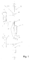
- FIG. 1 an overview of a multi-part closure is shown, which consists of a main lock 1 and a first and a second secondary lock 2, 3.
- Main lock and secondary locks 2, 3 can be coupled via spacers 4, 5.
- the main lock 1 has at least one latch and a lockable latch (not shown here), while the slave locks have traps and / or latches (eg: pivoting latches which drive in and out by means of a drive rod.)
- the coupling takes place in such a way that one below a cuff rail 6 of the main lock 1 guided drive rod 7 projects beyond this and forms an espagnolette 8, whose structure will be shown in more detail below.
- an espagnolette 11 is provided, which allows a coupling with the intermediate piece 4, 5 and which is configured according to the espagnolette 8.
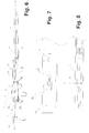
- FIGS. 2 and 3 is an espagnolette 8 or 11 shown on a larger scale.
- the espagnolette 8 has an over the Stulpschienenende 12 projecting drive rod portion 13, which consists predominantly of a tooth shoe 14 which is fixed to the drive rod 7.
- the inner longitudinal sides of the cross-sectionally U-shaped tooth shoe 14 are provided with a fine toothing 15.
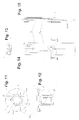
- a spacer pin 16 is mounted, which is evidenced by FIGS. 4 and 5 for supporting the drive rod portion 13 relative to a groove bottom 17 and a fold 18 is used.
- the faceplate 6 is flush with a fold 19, which has a fitting groove 20.
- a smooth fold is provided and the faceplate 6 is profiled in a U-shape.
- a cover plate 21 which consists of a substantially flat sheet metal section, at the end 22 a hook-like angled portion 23 is attached.
- the bend 23 passes through a keyhole-shaped recess 24 in the faceplate 6 and is dimensioned so that the distance 25 of parallel to the flat sheet metal portion extending U-leg 26 and the flat sheet metal portion 27 is dimensioned slightly larger than the faceplate 6 and the displaceable drive rod 7th As a result, the U-leg 26 engages under the drive rod.
- the U-leg 26 is dimensioned slightly wider than a slot-recess of the drive rod, the U-leg 26, the drive rod 7 close below the faceplate. 6
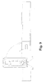
- the cover plate 21 is provided with a bore 28, which in the mounted position to Fig. 6 coaxial with a bore 29 of the faceplate 6 extends.
- a fixing screw 30 can thereby pass through the cover plate 21 and the faceplate 6. So that the drive rod 7 remains longitudinally displaceable, a slot 31 in the area of the fastening screw 30 is provided on the drive rod 7.
- a bend 32 pointing in the direction of the face-plate rail 6 is attached to the cover plate 21. This engages in an opening 33 of the faceplate 6 and thereby defines the escape of the cover plate 21 and the faceplate 6 relative to each other. At a load of the drive rod 7, this can in the drawing Fig. 6 bend upwards and displace the cover plate 21.
- the bend 32 engages under the face plate 6 and counteracts a lifting of the cover plate 21.
- Fig. 6 is the faceplate 10 and the drive rod 9 of the intermediate piece 5 indicated. It can be seen that the cover plate 21 covers the end of the cuff rails 6,10.
- the assembly of the cover plate 21 can be seen.
- the cover plate is pivoted by 90 ° relative to the faceplate 6 and with the U-leg 26 (FIG. Fig. 6 ) introduced into the opening 24.
- the cover plate 21 is parallel to the face-plate 6.
- a transport lock 35 is provided, which passes through the cover plate 21 in the bore 28 and locked in the bore 29.
- the multi-part closure after Fig. 1 adapt to the size of the wing by the secondary locks 2, 3 are positioned after the main lock 1 and the intermediate pieces 4, 5 have a cut-away, over a partial length 4 1 and 5 1 of the drive rod 9 of the intermediate piece 4, 5 with an external toothing is provided.
- the intermediate piece 4, 5 adapted according to the requirements by separating the unneeded section and drive-connected to the main lock 1 and the secondary locks 4, 5.
- a cut-to-length can be provided at both ends.
- the transport lock 35 is shown in detail.
- the transport lock 35 is designed as a mushroom-shaped pin whose widened head 36 is provided on the underside 37 with recesses 38, which are intended to facilitate an intervention of a tool.
- the hollow shaft 39 is divided by axially extending openings 40 in four spring tongues 41, which are provided at the end with locking projections 42.
- Chamfers 43 facilitate the installation of the transport lock 35.
- the cover plate 21 or the faceplate 6 is provided with beads 44 which are formed out of the sheet metal section 27.
- the beads 44 equalize a small material thickness of the U-shaped profiled faceplate 6.
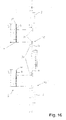
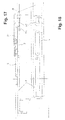
- FIG. 16 is a further embodiment of a multi-part closure can be seen in which fixed coupling points 45 are provided on the main lock 1 and the secondary lock 3, which are evidently the FIGS. 17, 18 provide a positive connection of the drive rods 7, 9, which are not ablnaturebar.
- the FIGS. 17, 18 take place the coupling of the drive rods 6, 9 via a spoon-shaped recess 45 in the drive rod 6, in which engages the complementarily shaped end of the drive rod 9.
- the end portion of the drive rod 7 is provided with a bottom 46.
- the spacers 4 , 5 interpret for certain requirements and accurate adjustment can be done by the partial lengths 4 1 , 5 1 yet.
Applications Claiming Priority (1)
| Application Number | Priority Date | Filing Date | Title |
|---|---|---|---|
| DE200920005885 DE202009005885U1 (de) | 2009-04-22 | 2009-04-22 | Treibstangenschloss mit Falle und Schubriegel |
Publications (2)
| Publication Number | Publication Date |
|---|---|
| EP2246508A2 true EP2246508A2 (fr) | 2010-11-03 |
| EP2246508A3 EP2246508A3 (fr) | 2011-09-28 |
Family
ID=40953472
Family Applications (1)
| Application Number | Title | Priority Date | Filing Date |
|---|---|---|---|
| EP10156979A Withdrawn EP2246508A3 (fr) | 2009-04-22 | 2010-03-19 | Crémone avec pêne demi-tour et verrou à coulisse |
Country Status (2)
| Country | Link |
|---|---|
| EP (1) | EP2246508A3 (fr) |
| DE (1) | DE202009005885U1 (fr) |
Cited By (4)
| Publication number | Priority date | Publication date | Assignee | Title |
|---|---|---|---|---|
| GB2496430A (en) * | 2011-11-11 | 2013-05-15 | Assa Abloy Ltd | Adjustable multipoint lock assembly |
| GB2511293A (en) * | 2013-02-04 | 2014-09-03 | Trojan Hardware & Design Ltd | Transmission mechanism |
| EP3070238B1 (fr) | 2015-03-16 | 2018-08-22 | Gretsch-Unitas GmbH Baubeschläge | Dispositif de verrouillage pour une porte ou une fenêtre |
| GB2567576A (en) * | 2011-11-11 | 2019-04-17 | Assa Abloy Ltd | Lock assemblies |
Families Citing this family (2)
| Publication number | Priority date | Publication date | Assignee | Title |
|---|---|---|---|---|
| FR3008445A1 (fr) * | 2013-07-11 | 2015-01-16 | Metalux | Serrures a mortaiser multipoints |
| DE102014118652B4 (de) | 2014-12-15 | 2022-12-22 | Drinkuth Aktiengsellschaft | Transportschutz für ein Fenster |
Citations (1)
| Publication number | Priority date | Publication date | Assignee | Title |
|---|---|---|---|---|
| DE3341004A1 (de) | 1983-11-12 | 1985-05-23 | Fa. Wilhelm Karrenberg, 5620 Velbert | Treibstangenschloss |
Family Cites Families (4)
| Publication number | Priority date | Publication date | Assignee | Title |
|---|---|---|---|---|
| DE6804099U (de) * | 1968-10-26 | 1969-03-06 | Weidtmann Fa Wilhelm | Kupplungsvorrichtung fuer ein verschlussgestaenge von fenstern od. dgl. |
| DE3416675A1 (de) * | 1984-05-05 | 1985-11-21 | Carl Fuhr Gmbh & Co, 5628 Heiligenhaus | Vorrichtung zum verbinden von treibstangenabschnitten eines treibstangenbeschlags, insbesondere drehkipp-beschlags fuer fenster, tueren oder dergleichen |
| IT1314886B1 (it) * | 2000-12-13 | 2003-01-16 | Euroinvest S R L | Collegamento meccanico d'uso all'interno di dispositivi di ancoraggioperimetrale di ante di infissi antieffrazione in profilato metallico |
| FR2900681B1 (fr) * | 2006-05-05 | 2008-07-04 | Tirard Soc Par Actions Simplif | Raccord de tringle d'huisserie |
-
2009
- 2009-04-22 DE DE200920005885 patent/DE202009005885U1/de not_active Expired - Lifetime
-
2010
- 2010-03-19 EP EP10156979A patent/EP2246508A3/fr not_active Withdrawn
Patent Citations (1)
| Publication number | Priority date | Publication date | Assignee | Title |
|---|---|---|---|---|
| DE3341004A1 (de) | 1983-11-12 | 1985-05-23 | Fa. Wilhelm Karrenberg, 5620 Velbert | Treibstangenschloss |
Cited By (7)
| Publication number | Priority date | Publication date | Assignee | Title |
|---|---|---|---|---|
| GB2496430A (en) * | 2011-11-11 | 2013-05-15 | Assa Abloy Ltd | Adjustable multipoint lock assembly |
| GB2567576A (en) * | 2011-11-11 | 2019-04-17 | Assa Abloy Ltd | Lock assemblies |
| GB2496430B (en) * | 2011-11-11 | 2019-05-08 | Assa Abloy Ltd | Lock assemblies |
| GB2567576B (en) * | 2011-11-11 | 2019-07-17 | Assa Abloy Ltd | Multipoint lock with adjustable connecting rod linkage |
| GB2511293A (en) * | 2013-02-04 | 2014-09-03 | Trojan Hardware & Design Ltd | Transmission mechanism |
| GB2511293B (en) * | 2013-02-04 | 2020-03-18 | Assa Abloy Ltd | Transmission mechanism |
| EP3070238B1 (fr) | 2015-03-16 | 2018-08-22 | Gretsch-Unitas GmbH Baubeschläge | Dispositif de verrouillage pour une porte ou une fenêtre |
Also Published As
| Publication number | Publication date |
|---|---|
| DE202009005885U1 (de) | 2009-08-13 |
| EP2246508A3 (fr) | 2011-09-28 |
Similar Documents
| Publication | Publication Date | Title |
|---|---|---|
| DE2313690C2 (de) | Treibstangenbeschlag für Fenster, Türen od.dgl | |
| EP2246508A2 (fr) | Crémone avec pêne demi-tour et verrou à coulisse | |
| EP2252751B1 (fr) | Ferrure de tige d entraînement pour une fenêtre ou une porte | |
| EP2602412B1 (fr) | Agencement de ferrure | |
| EP1439278A2 (fr) | Joint, notamment joint de contact ou joint automatiquement abaissable pour portes avec support adjustable | |
| EP1159502B1 (fr) | Fenetre ou porte | |
| EP2206860A2 (fr) | Armature dotée d'un élément de verrouillage démontable | |
| EP0493689B1 (fr) | Tringlerie de commande pour fenêtres, portes ou similaires | |
| EP2099989B1 (fr) | Crémone | |
| EP1264954B1 (fr) | Système de verouillage | |
| EP2754803A2 (fr) | Crémone de fenêtre ou de porte | |
| DE2450760C2 (de) | Riegelbeschlag für Fenster, Türen od.dgl. | |
| EP2295684B1 (fr) | Butée pour une fenêtre, une porte ou analogue, ainsi que fenêtre, porte ou analogue dotée d'une telle butée | |
| DE19737538C2 (de) | Befestigungseinrichtung | |
| EP2343425B1 (fr) | Agencement de rails de partie de ferrure pour une fenêtre, une porte, un clapet ou analogue | |
| DE69826866T2 (de) | Vorrichtung vom Typ Schraubenführung für Treibstangenbeschlag oder-verschluss | |
| EP3112577B1 (fr) | Joint abaissable | |
| EP3783176B1 (fr) | Ferrure de tige d'entraînement, fermeture de porte ou de fenêtre et agencement de porte ou de fenêtre | |
| EP3656955B1 (fr) | Gâche | |
| EP1977065B1 (fr) | Renvoi d'angle | |
| DE102009054644B4 (de) | Beschlagteilanordnung für ein Fenster, eine Tür, eine Klappe oder dergleichen | |
| DE202022105395U1 (de) | Verriegelungsvorrichtung und Türanordnung mit einer solchen Verriegelungsvorrichtung | |
| EP1260662B1 (fr) | Dispositif d'accouplement pour tringles d'entraínement de ferrures à tringles | |
| DE3206629A1 (de) | Mit einer stulpschienen-treibstangenbaueinheit vereinigtes treibstangengetriebe fuer baubeschlaege | |
| DE19734647A1 (de) | Beschlagteil an einem Flügel oder einem festen Rahmen eines Fensters, einer Tür od. dgl. |
Legal Events
| Date | Code | Title | Description |
|---|---|---|---|
| PUAI | Public reference made under article 153(3) epc to a published international application that has entered the european phase |
Free format text: ORIGINAL CODE: 0009012 |
|
| AK | Designated contracting states |
Kind code of ref document: A2 Designated state(s): AT BE BG CH CY CZ DE DK EE ES FI FR GB GR HR HU IE IS IT LI LT LU LV MC MK MT NL NO PL PT RO SE SI SK SM TR |
|
| AX | Request for extension of the european patent |
Extension state: AL BA ME RS |
|
| PUAL | Search report despatched |
Free format text: ORIGINAL CODE: 0009013 |
|
| AK | Designated contracting states |
Kind code of ref document: A3 Designated state(s): AT BE BG CH CY CZ DE DK EE ES FI FR GB GR HR HU IE IS IT LI LT LU LV MC MK MT NL NO PL PT RO SE SI SK SM TR |
|
| AX | Request for extension of the european patent |
Extension state: AL BA ME RS |
|
| RIC1 | Information provided on ipc code assigned before grant |
Ipc: E05C 9/20 20060101ALI20110822BHEP Ipc: E05C 9/00 20060101AFI20110822BHEP |
|
| STAA | Information on the status of an ep patent application or granted ep patent |
Free format text: STATUS: THE APPLICATION IS DEEMED TO BE WITHDRAWN |
|
| 18D | Application deemed to be withdrawn |
Effective date: 20120329 |