EP2246508A2 - Espagnolette with latchbolt and sliding bolt - Google Patents
Espagnolette with latchbolt and sliding bolt Download PDFInfo
- Publication number
- EP2246508A2 EP2246508A2 EP10156979A EP10156979A EP2246508A2 EP 2246508 A2 EP2246508 A2 EP 2246508A2 EP 10156979 A EP10156979 A EP 10156979A EP 10156979 A EP10156979 A EP 10156979A EP 2246508 A2 EP2246508 A2 EP 2246508A2
- Authority
- EP
- European Patent Office
- Prior art keywords
- drive rod
- faceplate
- lock according
- espagnolette
- espagnolette lock
- Prior art date
- Legal status (The legal status is an assumption and is not a legal conclusion. Google has not performed a legal analysis and makes no representation as to the accuracy of the status listed.)
- Withdrawn
Links
Images


Classifications
-
- E—FIXED CONSTRUCTIONS
- E05—LOCKS; KEYS; WINDOW OR DOOR FITTINGS; SAFES
- E05C—BOLTS OR FASTENING DEVICES FOR WINGS, SPECIALLY FOR DOORS OR WINDOWS
- E05C9/00—Arrangements of simultaneously actuated bolts or other securing devices at well-separated positions on the same wing
- E05C9/004—Faceplates ; Fixing the faceplates to the wing
-
- E—FIXED CONSTRUCTIONS
- E05—LOCKS; KEYS; WINDOW OR DOOR FITTINGS; SAFES
- E05C—BOLTS OR FASTENING DEVICES FOR WINGS, SPECIALLY FOR DOORS OR WINDOWS
- E05C9/00—Arrangements of simultaneously actuated bolts or other securing devices at well-separated positions on the same wing
- E05C9/20—Coupling means for sliding bars, rods, or cables
Definitions
- the invention relates to a drive rod lock with latch and sliding bolt according to the preamble of claim 1.
- a generic drive rod lock is already out of the DE 3341004 A1 known.
- espagnolette lock a main lock and a secondary lock is provided.
- the main lock can be drive-connected to the drive rod of the secondary lock via a drive rod coupling piece.
- a fixed drive rod coupling is provided on the main lock, in which a drive rod connection piece can be coupled.
- the end of the drive rod connecting piece can be connected via a pin bore connection with the drive rod of the secondary lock.
- the object is to provide a drive rod lock, which allows a flexible and easily adjustable distance of the secondary lock to the main lock and also minimizes the size of the secondary lock.
- the intermediate piece comprises a face-plate rail and a drive rod, so that the intermediate piece forms a compact component.
- a particularly advantageous embodiment provides that the drive rod coupling consists of a toothed shoe and an engaging in the tooth shoe along the longitudinal side edges toothed drive rod section, wherein the tooth shoe protrudes beyond the end of the cuff rail.
- the toothed longitudinal section of the drive rod can be deflected together with the faceplate.
- the drive rod coupling comprises a cover plate which covers the coupling region.
- the cover can be in a simple Fix the way at the connection point.
- the cover plate can simultaneously contribute to guiding the drive rod.
- a fastening element in the form of a screw can be provided to fix the cover plate.
- a bend pointing in the direction of the face-plate can be attached. This can interact with an opening of the faceplate and thereby determine the alignment of the cover plate and the faceplate.
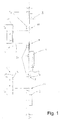
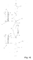
- FIG. 1 an overview of a multi-part closure is shown, which consists of a main lock 1 and a first and a second secondary lock 2, 3.
- Main lock and secondary locks 2, 3 can be coupled via spacers 4, 5.
- the main lock 1 has at least one latch and a lockable latch (not shown here), while the slave locks have traps and / or latches (eg: pivoting latches which drive in and out by means of a drive rod.)
- the coupling takes place in such a way that one below a cuff rail 6 of the main lock 1 guided drive rod 7 projects beyond this and forms an espagnolette 8, whose structure will be shown in more detail below.
- an espagnolette 11 is provided, which allows a coupling with the intermediate piece 4, 5 and which is configured according to the espagnolette 8.
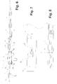
- FIGS. 2 and 3 is an espagnolette 8 or 11 shown on a larger scale.
- the espagnolette 8 has an over the Stulpschienenende 12 projecting drive rod portion 13, which consists predominantly of a tooth shoe 14 which is fixed to the drive rod 7.
- the inner longitudinal sides of the cross-sectionally U-shaped tooth shoe 14 are provided with a fine toothing 15.
- a spacer pin 16 is mounted, which is evidenced by FIGS. 4 and 5 for supporting the drive rod portion 13 relative to a groove bottom 17 and a fold 18 is used.
- the faceplate 6 is flush with a fold 19, which has a fitting groove 20.
- a smooth fold is provided and the faceplate 6 is profiled in a U-shape.
- a cover plate 21 which consists of a substantially flat sheet metal section, at the end 22 a hook-like angled portion 23 is attached.
- the bend 23 passes through a keyhole-shaped recess 24 in the faceplate 6 and is dimensioned so that the distance 25 of parallel to the flat sheet metal portion extending U-leg 26 and the flat sheet metal portion 27 is dimensioned slightly larger than the faceplate 6 and the displaceable drive rod 7th As a result, the U-leg 26 engages under the drive rod.
- the U-leg 26 is dimensioned slightly wider than a slot-recess of the drive rod, the U-leg 26, the drive rod 7 close below the faceplate. 6
- the cover plate 21 is provided with a bore 28, which in the mounted position to Fig. 6 coaxial with a bore 29 of the faceplate 6 extends.
- a fixing screw 30 can thereby pass through the cover plate 21 and the faceplate 6. So that the drive rod 7 remains longitudinally displaceable, a slot 31 in the area of the fastening screw 30 is provided on the drive rod 7.
- a bend 32 pointing in the direction of the face-plate rail 6 is attached to the cover plate 21. This engages in an opening 33 of the faceplate 6 and thereby defines the escape of the cover plate 21 and the faceplate 6 relative to each other. At a load of the drive rod 7, this can in the drawing Fig. 6 bend upwards and displace the cover plate 21.
- the bend 32 engages under the face plate 6 and counteracts a lifting of the cover plate 21.
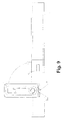
- Fig. 6 is the faceplate 10 and the drive rod 9 of the intermediate piece 5 indicated. It can be seen that the cover plate 21 covers the end of the cuff rails 6,10.
- the assembly of the cover plate 21 can be seen.
- the cover plate is pivoted by 90 ° relative to the faceplate 6 and with the U-leg 26 (FIG. Fig. 6 ) introduced into the opening 24.
- the cover plate 21 is parallel to the face-plate 6.
- a transport lock 35 is provided, which passes through the cover plate 21 in the bore 28 and locked in the bore 29.
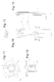
- the multi-part closure after Fig. 1 adapt to the size of the wing by the secondary locks 2, 3 are positioned after the main lock 1 and the intermediate pieces 4, 5 have a cut-away, over a partial length 4 1 and 5 1 of the drive rod 9 of the intermediate piece 4, 5 with an external toothing is provided.
- the intermediate piece 4, 5 adapted according to the requirements by separating the unneeded section and drive-connected to the main lock 1 and the secondary locks 4, 5.
- a cut-to-length can be provided at both ends.
- the transport lock 35 is shown in detail.
- the transport lock 35 is designed as a mushroom-shaped pin whose widened head 36 is provided on the underside 37 with recesses 38, which are intended to facilitate an intervention of a tool.
- the hollow shaft 39 is divided by axially extending openings 40 in four spring tongues 41, which are provided at the end with locking projections 42.
- Chamfers 43 facilitate the installation of the transport lock 35.
- the cover plate 21 or the faceplate 6 is provided with beads 44 which are formed out of the sheet metal section 27.
- the beads 44 equalize a small material thickness of the U-shaped profiled faceplate 6.
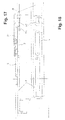
- FIG. 16 is a further embodiment of a multi-part closure can be seen in which fixed coupling points 45 are provided on the main lock 1 and the secondary lock 3, which are evidently the FIGS. 17, 18 provide a positive connection of the drive rods 7, 9, which are not ablnaturebar.
- the FIGS. 17, 18 take place the coupling of the drive rods 6, 9 via a spoon-shaped recess 45 in the drive rod 6, in which engages the complementarily shaped end of the drive rod 9.
- the end portion of the drive rod 7 is provided with a bottom 46.
- the spacers 4 , 5 interpret for certain requirements and accurate adjustment can be done by the partial lengths 4 1 , 5 1 yet.
Abstract
Description
Die Erfindung betrifft ein Treibstangenschloss mit Falle und Schubriegel nach dem Oberbegriff des Anspruchs 1. Ein gattungsgemäßes Treibstangeschloss ist bereits aus der
Bei diesem bekannten Treibstangenschloss ist ein Hauptschloss und ein Nebenschloss vorgesehen. Das Hauptschloss lässt sich über ein Treibstangenkopplungsstück mit der Treibstange des Nebenschlosses antriebsverbinden. Dazu ist an dem Hauptschloss eine fixe Treibstangenkupplung vorgesehen, in die ein Treibstangenanschlussstück einkoppelbar ist. Das Ende des Treibstangenanschlussstückes kann über eine Zapfenbohrungsverbindung mit der Treibstange des Nebenschlosses verbunden werden. Nachteilig dabei ist es, dass die Stulpschiene des Nebenschlosses bis annähernd an das Hauptschloss heranreichen muss und dass das Treibstangenanschlussstück eine fixe Länge aufweist. Dadurch kann der Abstand des Nebenschlosses zum Hauptschloss nicht oder nur unter großem Aufwand variiert werden.In this known espagnolette lock a main lock and a secondary lock is provided. The main lock can be drive-connected to the drive rod of the secondary lock via a drive rod coupling piece. For this purpose, a fixed drive rod coupling is provided on the main lock, in which a drive rod connection piece can be coupled. The end of the drive rod connecting piece can be connected via a pin bore connection with the drive rod of the secondary lock. The disadvantage here is that the faceplate of the secondary lock must come close to the main lock and that the drive rod connecting piece has a fixed length. As a result, the distance between the secondary lock and the main lock can not be varied or only at great expense.
Ausgehend davon besteht die Aufgabe, ein Treibstangenschloss bereitzustellen, welches einen flexiblen und leicht anpassbaren Abstand des Nebenschlosses zum Hauptschloss zulässt und auch die Baugröße des Nebenschlosses minimiert.Based on this, the object is to provide a drive rod lock, which allows a flexible and easily adjustable distance of the secondary lock to the main lock and also minimizes the size of the secondary lock.
Diese Aufgabe wird auf einfache Art und Weise durch den kennzeichnenden Teil des Anspruchs 1 gelöst. Durch die beanspruchte Anordnung eines Zwischenstücks wird ein mehrteiliger Verschluss möglich, der durch verschiedene Zwischenstücke eine maßliche Anpassung an die Flügelgröße zulässt, wobei das Hauptschloss und die Nebenschlösser jeweils Standardabmessungen erhalten können.This object is achieved in a simple manner by the characterizing part of claim 1. By the claimed arrangement of an intermediate piece a multi-part closure is possible, which allows a dimensional adjustment to the wing size by means of various intermediate pieces, wherein the main lock and the secondary locks can each receive standard dimensions.
Besonders vorteilhaft ist es, wenn das Zwischenstück eine Stulpschiene und eine Treibstange umfasst, so dass das Zwischenstück ein kompaktes Bauteil bildet.It is particularly advantageous if the intermediate piece comprises a face-plate rail and a drive rod, so that the intermediate piece forms a compact component.
Eine besonders vorteilhafte Ausgestaltung sieht vor, dass die Treibstangenkupplung aus einem Zahnschuh und einem in den Zahnschuh eingreifenden entlang der Längsseitenkanten verzahnten Treibstangenabschnitt besteht, wobei der Zahnschuh über das Stulpschienenende vorragt. Durch diese Anordnung lässt sich eine sehr variable und nahezu beliebige Ausrichtung der Nebenschlösser in Bezug auf das Hauptschloss erreichen. Dies ist insbesondere im Hinblick auf einen Reparaturfall eines vorhandenen Schlosses besonders vorteilhaft, da hier die Riegeleingriffe der Nebenschlösser festgelegt sind und die Nebenschlösser daher einen vorgegebenen Abstand zum Hauptschloss einhalten müssen.A particularly advantageous embodiment provides that the drive rod coupling consists of a toothed shoe and an engaging in the tooth shoe along the longitudinal side edges toothed drive rod section, wherein the tooth shoe protrudes beyond the end of the cuff rail. By this arrangement, a very variable and almost any orientation of the secondary locks with respect to the main lock can be achieved. This is particularly advantageous in particular with regard to a repair case of an existing lock, since here the bolt engagements of the auxiliary locks are fixed and the secondary locks therefore have to maintain a predetermined distance from the main lock.
Zur einfachen Anpassung ist es dabei zweckmäßig, dass der verzahnte Längenabschnitt der Treibstange zusammen mit der Stulpschiene ablenkbar ist.For easy adaptation, it is expedient that the toothed longitudinal section of the drive rod can be deflected together with the faceplate.
Um ein Auskoppeln der Treibstangenkupplung zu verhindern und die Verbindungsstelle des Zwischenstücks mit dem benachbarten Hauptschloss und dem Nebenschlosses zu verdecken, ist vorgesehen, dass die Treibstangenkupplung eine Abdeckplatte umfasst, welche den Kopplungsbereich überdeckt.In order to prevent a coupling of the drive rod coupling and to cover the connection point of the intermediate piece with the adjacent main lock and the secondary lock, it is provided that the drive rod coupling comprises a cover plate which covers the coupling region.
Um die Montage der Abdeckplatte zu erleichtern, ist dabei vorgesehen, dass in dieser aus einem im Wesentlichen ebenen Blechabschnitt besteht, der an einem Ende eine U-förmige hakenartige Abwinkelung aufweist.In order to facilitate the mounting of the cover plate, it is provided that in this consists of a substantially planar sheet metal section having a U-shaped hook-like angled at one end.
Wenn die Abwinkelung einer Ausnehmung in der Stulpschiene zuordnenbar ist und dabei der Abstand des parallel zum ebenen Blechabschnitt verlaufenden U-Schenkels und des ebenen Blechabschnitts geringfügig größer bemessen ist als die Stärke der Stulpschiene und der darunter verschiebbar geführten Treibstange, dann lässt sich die Abdeckplatte in einfacher Weise an der Verbindungsstelle fixieren.If the bend of a recess in the faceplate is zuordnenbar and the distance between the plane parallel to the flat plate portion extending U-leg and the flat sheet metal portion is dimensioned slightly larger than the thickness of the faceplate and the displaceably guided below drive rod, then the cover can be in a simple Fix the way at the connection point.
Hat die hakenartige Abwinkelung einen in Längsrichtung T-förmigen Querschnitt, dessen verbreiteter T-Steg größer bemessen ist als die Breite einer Langlochausnehmung in der Treibstange, dann kann die Abdeckplatte gleichzeitig zur Führung der Treibstange beitragen.If the hook-like bend has a T-shaped cross-section in the longitudinal direction, the widened T-bridge of which is dimensioned larger than the width of a slot recess in the drive rod, then the cover plate can simultaneously contribute to guiding the drive rod.
Zur Montage der Abdeckplatte ist dabei vorgesehen, dass nahe dem Ende der Abdeckplatte, an denen die Hakenartige Abwinkelung angebracht ist, eine Bohrung für ein Befestigungselement angebracht ist. Dadurch kann ein Befestigungselement in Form einer Schraube vorgesehen werden, um die Abdeckplatte zu fixieren.For mounting the cover plate is provided that near the end of the cover plate on which the hook-like bend is attached, a hole for a fastener is mounted. Thereby, a fastening element in the form of a screw can be provided to fix the cover plate.
Schließlich kann zur vorübergehenden Fixierung der Ausrichtung der Abdeckplatte nahe des der Abwinkelung entfernt liegenden Endes eine in Richtung der Stulpschiene weisende Abwinkelung angebracht sein. Diese kann mit einer Öffnung der Stulpschiene zusammenwirken und dadurch die Flucht der Abdeckplatte und der Stulpschiene festlegen.Finally, for temporarily fixing the orientation of the cover plate near the end remote from the bend, a bend pointing in the direction of the face-plate can be attached. This can interact with an opening of the faceplate and thereby determine the alignment of the cover plate and the faceplate.
Zweckmäßig ist es daher, dass an dem Stulpschienenende eine entfernt von diesem angebrachte langlochförmige Ausnehmung zur Aufnahme der hakenartigen Abwinkelung und eine nahe dem Ende angeordnete schlüssellochförmige Öffnung vorgesehen ist.It is expedient, therefore, that at the end of the cuff rail remote from this slot-shaped recess for receiving the hook-like bend and a near the end arranged keyhole-shaped opening is provided.
Weitere vorteilhafte Ausgestaltungen ergeben sich aus den Zeichnungen. Es zeigt
- Fig. 1
- eine schematische Übersicht eines Treibstangenschlosses,
- Fig. 2
- einen vergrößerten Ausschnitt einer Kopplungsstelle in noch nicht endgültig montiertem Zustand mit einer Transportsicherung in einem Längsschnitt,
- Fig. 3
- eine Darstellung der Kopplungsstelle nach
Fig. 2 in einer Draufsicht, - Fig. 4
- einen Querschnitt der Kopplungsstelle entlang der Linie IV-IV in
Fig. 3 in einem ersten Ausführungsbeispiel, - Fig. 5
- einen Querschnitt der Kopplungsstelle entlang der Linie IV-IV in
Fig. 3 mit einer U-förmigen Stulpschiene, - Fig. 6
- eine Ansicht nach
Fig. 2 mit einem angedeuteten Befestigungselement im endgültig montierten Zustand, - Fig. 7
- eine Stulpschiene im Bereich der Kopplungsstelle,
- Fig. 8
- eine Treibstange im Bereich der Kopplungsstelle,
- Fig. 9
- die Montage der Abdeckplatte an dem Treibstangenschloss,
- Fig. 10
- die Beweglichkeit der bereits montierten Abdeckplatte,
- Fig. 11
- eine Transportsicherung in einer Ansicht von unten,
- Fig. 12
- eine Transportsicherung in einer Seitenansicht,
- Fig. 13
- einen Querschnitt einer Kopplungsverbindung eines mit einem profilierten Stulp ausgestatteten Treibstangenschlosses entlang der Linie XIII-XIII in
Fig. 14 , - Fig. 14
- eine Draufsicht auf eine Kopplungsverbindung nach
Fig. 13 , - Fig. 15
- einen Längsschnitt der Kopplungsverbindung nach
Fig. 13 , - Fig. 16
- ein weiteres Ausführungsbeispiel, bei dem an dem Hauptschloss fixe Kopplungsstellen vorgesehen sind,
- Fig. 17
- eine fixe, nicht ablängbare Kopplungsstelle in einem Längsmittelschnitt und
- Fig. 18
- eine Kopplungsstelle nach
Fig. 17 in einer Draufsicht.
- Fig. 1
- a schematic overview of a drive rod lock,
- Fig. 2
- an enlarged section of a coupling point in not yet finally mounted state with a transport lock in a longitudinal section,
- Fig. 3
- a representation of the coupling point after
Fig. 2 in a plan view, - Fig. 4
- a cross section of the coupling point along the line IV-IV in
Fig. 3 in a first embodiment, - Fig. 5
- a cross section of the coupling point along the line IV-IV in
Fig. 3 with a U-shaped faceplate, - Fig. 6
- a view
Fig. 2 with an indicated fastener in the final assembled state, - Fig. 7
- a faceplate in the area of the coupling point,
- Fig. 8
- a drive rod in the region of the coupling point,
- Fig. 9
- the mounting of the cover plate to the espagnolette lock,
- Fig. 10
- the mobility of the already mounted cover plate,
- Fig. 11
- a transport lock in a view from below,
- Fig. 12
- a transport safety device in a side view,
- Fig. 13
- a cross-section of a coupling connection of a provided with a profiled forend espagnolette along the line XIII-XIII in
Fig. 14 . - Fig. 14
- a plan view of a coupling connection according to
Fig. 13 . - Fig. 15
- a longitudinal section of the coupling connection according to
Fig. 13 . - Fig. 16
- a further embodiment in which fixed coupling points are provided on the main lock,
- Fig. 17
- a fixed, not ablängbare coupling site in a longitudinal central section and
- Fig. 18
- a coupling point after
Fig. 17 in a top view.
In der
Das als Treibstangenanschlussbauteil ausgelegte Zwischenstück 4, 5 besteht ebenfalls aus einer Treibstange 9 und einer Stulpschiene 10. An dem Nebenschloss 2, 3 ist eine Treibstangenkupplung 11 vorgesehen, welche eine Kupplung mit dem Zwischenstück 4, 5 ermöglicht und die entsprechend der Treibstangenkupplung 8 ausgestaltet ist.At the
In den
Insbesondere aus den
Da gleichzeitig vorgesehen ist - wie anhand der
Die Abdeckplatte 21 ist mit einer Bohrung 28 versehen, welche in montierter Stellung nach
In der
In der
Bedingt durch diese Ausgestaltung lässt sich der mehrteilige Verschluss nach
Aus der
In den
Aus den
Aus
Bedingt durch diese Ausgestaltung lassen sich die Zwischenstücke 4, 5 für bestimmte Anforderungen auslegen und eine genaue Anpassung kann durch die Teillängen 41 , 51 dennoch erfolgen.Due to this configuration, the spacers 4 , 5 interpret for certain requirements and accurate adjustment can be done by the partial lengths 4 1 , 5 1 yet.
Abschließend sei darauf hingewiesen, dass neben der Anordnung nach den
- 11
- Hauptschlossmain lock
- 22
- NebenschlossBesides Castle
- 33
- NebenschlossBesides Castle
- 44
- Zwischenstückconnecting piece
- 41 4 1
- Teillängepartial length
- 55
- Zwischenstückconnecting piece
- 51 5 1
- Teillängepartial length
- 66
- Stulpschienefaceplate
- 77
- Treibstangedriving rod
- 88th
- TreibstangenkupplungDriving rod coupling
- 99
- Treibstangedriving rod
- 1010
- Stulpschienefaceplate
- 1111
- TreibstangenkupplungDriving rod coupling
- 1212
- StulpschienenendeStulpschienenende
- 1313
- TreibstangenabschnittRod part
- 1414
- Zahnschuhtooth Shoe
- 1515
- Feinverzahnungfine toothing
- 1616
- Distanzzapfenspacer pins
- 1717
- Nutgrundgroove base
- 1818
- Falzfold
- 1919
- Falzfold
- 2020
- Beschlagnutfitting groove
- 2121
- Abdeckplattecover
- 211 21 1
- Pfeilarrow
- 2222
- EndeThe End
- 2323
- Abwinkelungangulation
- 2424
- Ausnehmungrecess
- 2525
- Abstanddistance
- 2626
- U-SchenkelU-leg
- 2727
- Blechabschnittsheet metal section
- 2828
- Bohrungdrilling
- 2929
- Bohrungdrilling
- 3030
- Befestigungsschraubefixing screw
- 3131
- LangochLangoch
- 3232
- Abwinkelungangulation
- 3333
- Öffnungopening
- 3434
- Stegweb
- 3535
- Transportsicherungtransport safety
- 3636
- Kopfhead
- 3737
- Unterseitebottom
- 3838
- Ausnehmungenrecesses
- 3939
- Schaftshaft
- 4040
- Durchbruchbreakthrough
- 4141
- Federzungenspring tongues
- 4242
- Rastvorsprungcatch projection
- 4343
- Fasechamfer
- 4444
- SickeBeading
- 4545
- Ausnehmungrecess
- 4646
- Bodenground
Claims (11)
Applications Claiming Priority (1)
| Application Number | Priority Date | Filing Date | Title |
|---|---|---|---|
| DE200920005885 DE202009005885U1 (en) | 2009-04-22 | 2009-04-22 | Espagnolette lock with latch and deadbolt |
Publications (2)
| Publication Number | Publication Date |
|---|---|
| EP2246508A2 true EP2246508A2 (en) | 2010-11-03 |
| EP2246508A3 EP2246508A3 (en) | 2011-09-28 |
Family
ID=40953472
Family Applications (1)
| Application Number | Title | Priority Date | Filing Date |
|---|---|---|---|
| EP10156979A Withdrawn EP2246508A3 (en) | 2009-04-22 | 2010-03-19 | Espagnolette with latchbolt and sliding bolt |
Country Status (2)
| Country | Link |
|---|---|
| EP (1) | EP2246508A3 (en) |
| DE (1) | DE202009005885U1 (en) |
Cited By (4)
| Publication number | Priority date | Publication date | Assignee | Title |
|---|---|---|---|---|
| GB2496430A (en) * | 2011-11-11 | 2013-05-15 | Assa Abloy Ltd | Adjustable multipoint lock assembly |
| GB2511293A (en) * | 2013-02-04 | 2014-09-03 | Trojan Hardware & Design Ltd | Transmission mechanism |
| EP3070238B1 (en) | 2015-03-16 | 2018-08-22 | Gretsch-Unitas GmbH Baubeschläge | Locking device for a door or a window |
| GB2567576A (en) * | 2011-11-11 | 2019-04-17 | Assa Abloy Ltd | Lock assemblies |
Families Citing this family (2)
| Publication number | Priority date | Publication date | Assignee | Title |
|---|---|---|---|---|
| FR3008445A1 (en) * | 2013-07-11 | 2015-01-16 | Metalux | LOCKS TO MORTISIZE MULTIPOINTS |
| DE102014118652B4 (en) | 2014-12-15 | 2022-12-22 | Drinkuth Aktiengsellschaft | Transport protection for a window |
Citations (1)
| Publication number | Priority date | Publication date | Assignee | Title |
|---|---|---|---|---|
| DE3341004A1 (en) | 1983-11-12 | 1985-05-23 | Fa. Wilhelm Karrenberg, 5620 Velbert | Espagnolette lock |
Family Cites Families (4)
| Publication number | Priority date | Publication date | Assignee | Title |
|---|---|---|---|---|
| DE6804099U (en) * | 1968-10-26 | 1969-03-06 | Weidtmann Fa Wilhelm | COUPLING DEVICE FOR A LOCKING ROD OF WINDOWS OD. DGL. |
| DE3416675A1 (en) * | 1984-05-05 | 1985-11-21 | Carl Fuhr Gmbh & Co, 5628 Heiligenhaus | DEVICE FOR CONNECTING DRIVE ROD SECTIONS OF A DRIVE ROD FITTING, IN PARTICULAR TURNTABLE FITTING FOR WINDOWS, DOORS OR THE LIKE |
| IT1314886B1 (en) * | 2000-12-13 | 2003-01-16 | Euroinvest S R L | MECHANICAL CONNECTION OF USE INSIDE PERIMETER ANCHORING DEVICES FOR ANTI-THEFT FRAME DOORS IN METAL PROFILE |
| FR2900681B1 (en) * | 2006-05-05 | 2008-07-04 | Tirard Soc Par Actions Simplif | HINGED RING FITTING |
-
2009
- 2009-04-22 DE DE200920005885 patent/DE202009005885U1/en not_active Expired - Lifetime
-
2010
- 2010-03-19 EP EP10156979A patent/EP2246508A3/en not_active Withdrawn
Patent Citations (1)
| Publication number | Priority date | Publication date | Assignee | Title |
|---|---|---|---|---|
| DE3341004A1 (en) | 1983-11-12 | 1985-05-23 | Fa. Wilhelm Karrenberg, 5620 Velbert | Espagnolette lock |
Cited By (7)
| Publication number | Priority date | Publication date | Assignee | Title |
|---|---|---|---|---|
| GB2496430A (en) * | 2011-11-11 | 2013-05-15 | Assa Abloy Ltd | Adjustable multipoint lock assembly |
| GB2567576A (en) * | 2011-11-11 | 2019-04-17 | Assa Abloy Ltd | Lock assemblies |
| GB2496430B (en) * | 2011-11-11 | 2019-05-08 | Assa Abloy Ltd | Lock assemblies |
| GB2567576B (en) * | 2011-11-11 | 2019-07-17 | Assa Abloy Ltd | Multipoint lock with adjustable connecting rod linkage |
| GB2511293A (en) * | 2013-02-04 | 2014-09-03 | Trojan Hardware & Design Ltd | Transmission mechanism |
| GB2511293B (en) * | 2013-02-04 | 2020-03-18 | Assa Abloy Ltd | Transmission mechanism |
| EP3070238B1 (en) | 2015-03-16 | 2018-08-22 | Gretsch-Unitas GmbH Baubeschläge | Locking device for a door or a window |
Also Published As
| Publication number | Publication date |
|---|---|
| DE202009005885U1 (en) | 2009-08-13 |
| EP2246508A3 (en) | 2011-09-28 |
Similar Documents
| Publication | Publication Date | Title |
|---|---|---|
| DE2313690C2 (en) | Espagnolette for windows, doors or the like | |
| EP2246508A2 (en) | Espagnolette with latchbolt and sliding bolt | |
| EP3258044B1 (en) | Wing assembly and method for head-on mounting of a fitting element in such a wing assembly | |
| EP2252751B1 (en) | Espagnolette fitting for window or door | |
| EP2602412B1 (en) | Fitting device | |
| EP1439278A2 (en) | Seal, in particular contact seal or automatically lowerable floor seal for doors with adjustable mounting | |
| EP1159502B1 (en) | Window or door | |
| EP2206860A2 (en) | Fitting with extendable lock element | |
| EP0493689B1 (en) | Espagnolette for windows, doors or the like | |
| DE19740603C2 (en) | Forend rail fastening | |
| EP2099989B1 (en) | Driving rod gear | |
| EP1264954B1 (en) | Locking device | |
| EP2754803A2 (en) | Espagnolette fitting for a window or a door | |
| DE2450760C2 (en) | Bolt fitting for windows, doors or the like. | |
| EP2295684B1 (en) | Lining for a window, door or similar and window, door or similar with such a lining | |
| DE19737538C2 (en) | Fastening device | |
| EP2343425B1 (en) | Fitting rail assembly for a window, door, flap or similar | |
| DE69826866T2 (en) | Device of type screw guide for espagnolette fitting or closure | |
| EP3112577B1 (en) | Drop-down seal | |
| EP3783176B1 (en) | Drive rod fitting, door or window closure and door or window assembly | |
| EP3656955B1 (en) | Striker | |
| EP1977065B1 (en) | Corner deflection | |
| DE102009054644B4 (en) | Fitting assembly for a window, a door, a flap or the like | |
| DE202022105395U1 (en) | Locking device and door assembly with such a locking device | |
| EP1260662B1 (en) | Coupling device for drive rods of fittings with drive rods |
Legal Events
| Date | Code | Title | Description |
|---|---|---|---|
| PUAI | Public reference made under article 153(3) epc to a published international application that has entered the european phase |
Free format text: ORIGINAL CODE: 0009012 |
|
| AK | Designated contracting states |
Kind code of ref document: A2 Designated state(s): AT BE BG CH CY CZ DE DK EE ES FI FR GB GR HR HU IE IS IT LI LT LU LV MC MK MT NL NO PL PT RO SE SI SK SM TR |
|
| AX | Request for extension of the european patent |
Extension state: AL BA ME RS |
|
| PUAL | Search report despatched |
Free format text: ORIGINAL CODE: 0009013 |
|
| AK | Designated contracting states |
Kind code of ref document: A3 Designated state(s): AT BE BG CH CY CZ DE DK EE ES FI FR GB GR HR HU IE IS IT LI LT LU LV MC MK MT NL NO PL PT RO SE SI SK SM TR |
|
| AX | Request for extension of the european patent |
Extension state: AL BA ME RS |
|
| RIC1 | Information provided on ipc code assigned before grant |
Ipc: E05C 9/20 20060101ALI20110822BHEP Ipc: E05C 9/00 20060101AFI20110822BHEP |
|
| STAA | Information on the status of an ep patent application or granted ep patent |
Free format text: STATUS: THE APPLICATION IS DEEMED TO BE WITHDRAWN |
|
| 18D | Application deemed to be withdrawn |
Effective date: 20120329 |