EP3070238B1 - Dispositif de verrouillage pour une porte ou une fenêtre - Google Patents
Dispositif de verrouillage pour une porte ou une fenêtre Download PDFInfo
- Publication number
- EP3070238B1 EP3070238B1 EP15159130.2A EP15159130A EP3070238B1 EP 3070238 B1 EP3070238 B1 EP 3070238B1 EP 15159130 A EP15159130 A EP 15159130A EP 3070238 B1 EP3070238 B1 EP 3070238B1
- Authority
- EP
- European Patent Office
- Prior art keywords
- lock
- locking device
- drive rod
- main
- coupled
- Prior art date
- Legal status (The legal status is an assumption and is not a legal conclusion. Google has not performed a legal analysis and makes no representation as to the accuracy of the status listed.)
- Active
Links
- 230000008878 coupling Effects 0.000 claims description 6
- 238000010168 coupling process Methods 0.000 claims description 6
- 238000005859 coupling reaction Methods 0.000 claims description 6
- 230000000881 depressing effect Effects 0.000 description 3
- 238000006073 displacement reaction Methods 0.000 description 3
- 238000009434 installation Methods 0.000 description 2
- 238000000034 method Methods 0.000 description 2
- 230000005540 biological transmission Effects 0.000 description 1
- 230000000903 blocking effect Effects 0.000 description 1
- 238000010276 construction Methods 0.000 description 1
- 230000001960 triggered effect Effects 0.000 description 1
Images


Classifications
-
- E—FIXED CONSTRUCTIONS
- E05—LOCKS; KEYS; WINDOW OR DOOR FITTINGS; SAFES
- E05C—BOLTS OR FASTENING DEVICES FOR WINGS, SPECIALLY FOR DOORS OR WINDOWS
- E05C9/00—Arrangements of simultaneously actuated bolts or other securing devices at well-separated positions on the same wing
- E05C9/02—Arrangements of simultaneously actuated bolts or other securing devices at well-separated positions on the same wing with one sliding bar for fastening when moved in one direction and unfastening when moved in opposite direction; with two sliding bars moved in the same direction when fastening or unfastening
- E05C9/026—Arrangements of simultaneously actuated bolts or other securing devices at well-separated positions on the same wing with one sliding bar for fastening when moved in one direction and unfastening when moved in opposite direction; with two sliding bars moved in the same direction when fastening or unfastening comprising key-operated locks, e.g. a lock cylinder to drive auxiliary deadbolts or latch bolts
-
- E—FIXED CONSTRUCTIONS
- E05—LOCKS; KEYS; WINDOW OR DOOR FITTINGS; SAFES
- E05B—LOCKS; ACCESSORIES THEREFOR; HANDCUFFS
- E05B63/00—Locks or fastenings with special structural characteristics
- E05B63/14—Arrangement of several locks or locks with several bolts, e.g. arranged one behind the other
-
- E—FIXED CONSTRUCTIONS
- E05—LOCKS; KEYS; WINDOW OR DOOR FITTINGS; SAFES
- E05C—BOLTS OR FASTENING DEVICES FOR WINGS, SPECIALLY FOR DOORS OR WINDOWS
- E05C9/00—Arrangements of simultaneously actuated bolts or other securing devices at well-separated positions on the same wing
- E05C9/04—Arrangements of simultaneously actuated bolts or other securing devices at well-separated positions on the same wing with two sliding bars moved in opposite directions when fastening or unfastening
- E05C9/047—Arrangements of simultaneously actuated bolts or other securing devices at well-separated positions on the same wing with two sliding bars moved in opposite directions when fastening or unfastening comprising key-operated locks, e.g. a lock cylinder to drive auxiliary deadbolts or latch bolts
-
- E—FIXED CONSTRUCTIONS
- E05—LOCKS; KEYS; WINDOW OR DOOR FITTINGS; SAFES
- E05B—LOCKS; ACCESSORIES THEREFOR; HANDCUFFS
- E05B63/00—Locks or fastenings with special structural characteristics
- E05B63/18—Locks or fastenings with special structural characteristics with arrangements independent of the locking mechanism for retaining the bolt or latch in the retracted position
- E05B63/20—Locks or fastenings with special structural characteristics with arrangements independent of the locking mechanism for retaining the bolt or latch in the retracted position released automatically when the wing is closed
-
- E—FIXED CONSTRUCTIONS
- E05—LOCKS; KEYS; WINDOW OR DOOR FITTINGS; SAFES
- E05C—BOLTS OR FASTENING DEVICES FOR WINGS, SPECIALLY FOR DOORS OR WINDOWS
- E05C9/00—Arrangements of simultaneously actuated bolts or other securing devices at well-separated positions on the same wing
- E05C9/18—Details of fastening means or of fixed retaining means for the ends of bars
- E05C9/1825—Fastening means
- E05C9/1833—Fastening means performing sliding movements
- E05C9/1841—Fastening means performing sliding movements perpendicular to actuating bar
Definitions
- the present invention relates to a locking device for a door or a window with a main lock serving for actuation, at least a first secondary lock with a closure element of a first type and with a forend serving for attachment, wherein the first secondary lock coupled to the main lock and operable by the main lock is.
- Locking devices and multipoint locks are known in the art.
- a locking device which has a main lock and two identical secondary locks.
- Main lock and secondary locks are coupled by means of a drive rod, so that the main lock and secondary locks are operated together.
- the main lock is designed as a self-locking automatic lock that automatically closes a spring-biased latch bolt when the case of the main lock, by hitting the trap on a door frame. This also closes the secondary locks coupled to the main lock.
- the main lock and secondary locks can only be operated together. Blocked one of the locks during the closing process, eg. due to delay of the door and / or the door frame as a result of setting operations, temperature-induced strains or a break-in attempt, so the other locks can not or not completely close. As a result, there is a risk of compromising the safety and reliability of such a locking device during operation.
- a closing device with wing catching device in which a wing catcher and an additional lock can be actuated by a main lock means of drive rods.
- the DE 298 02 967 U1 relates to a mortise lock for an outer door with a main lock box, wherein a locking box and a Sperrschwenkbügelschreib are actuated by means of connecting rods and tie rods connected thereto.
- the present invention has for its object to enable with simple structural means reliable operation of a locking device.
- the above object is achieved by a locking device having the features of claim 1.
- the locking device is characterized in that the main lock and the first secondary lock are coupled by means of a first drive rod, that the first drive rod has two separate sections, which are coupled via a connector and that the connector has a passage for passing the closing element of the second secondary lock having.
- the auxiliary locks are separate and spatially separated from the main lock.
- the spacing of the secondary locks from the main lock can be chosen such that the main lock and secondary locks are evenly distributed along the height of the door or window.
- the fact that the first secondary lock and the second secondary lock are operated independently of each other or can be actuated, the door or window can still be closed securely even if one of the secondary locks is damaged. For example, a secondary lock may be damaged but functionally unaffected.
- Main lock and secondary locks are separate and spatially separated from each other, i. each spaced apart.
- the distance between the mutually facing housing edges of the lock housing adjacent locks can be greater than 20 centimeters, in particular between greater than 20 and 80 centimeters, preferably between 30 and 70 centimeters, more preferably between 40 and 60 centimeters.
- first secondary locks and two second secondary locks are present, which are each coupled to the main lock and actuated by the main lock.
- the first secondary locks can be coupled to the main lock in such a way that they can be actuated together.
- the second secondary locks are also coupled to the main lock so that they can be operated together.
- the first and second secondary locks can be operated separately and independently of each other.
- the second secondary lock can be arranged in the longitudinal direction between the main lock and the first secondary lock. It is conceivable that the main lock is arranged in the face length direction centered to the forend. Thus, in the closed state of the locks a secure connection of the door or the window on the associated frame or strike plate is realized, since two locks with different types of closure elements are arranged on at least one side of the main lock. In the case of two first secondary locks and two second secondary locks, a lock pair consisting of a first secondary lock and a second secondary lock is thus arranged in the face-plate direction on both sides of the main lock. Thus, a uniform fixation of the Mosanrahmen or strike plate and therefore a uniform closing pressure is realized over the entire length of stay or height of the door.
- the main lock and the first secondary lock are coupled by means of a first drive rod.
- a reliable coupling between the main lock and the first secondary lock is realized with simple structural means and with a small space requirement, so that the first secondary lock can be driven by the main lock.
- the closing element of the first type of the first secondary lock can be moved from an open position to a closed position and opened again if necessary.
- main lock and the second secondary lock are coupled by means of a second drive rod.
- the second drive rod is actuated independently of the first drive rod through the main lock.
- the first drive rod has two separate sections, which are coupled via a connecting piece.
- the connector may be slidably guided on the second secondary lock.
- the connecting piece between a lock housing of the second secondary lock and the forend is guided displaceably, for example in a corresponding recess.
- the connecting piece is translationally movable in the face-plate direction. Forces can be transmitted in the direction of actuation, from the main lock to the first secondary lock arranged at the end.
- the connecting piece is displaceable along the cuff longitudinal direction between a first, lower position and a second, upper position.
- the connecting piece has a passage for the passage of the closing element of the second Mauzzies on.
- the passage is formed such that it is formed larger in the displacement direction of the connecting piece than the height of the closing element of the second secondary lock.
- the passage corresponds in height to the sum of the height of the closing element of the second secondary lock and the length of the displacement path of the connecting piece between the first position and the second position.
- the connector may have end-side recesses for coupling with the portions of the first drive rod. It is conceivable that the recesses have a T-shaped, peg-shaped or rectangular cross-section. This cross section is particularly suitable for producing a positive connection.
- the ends of the first drive rods, which are coupled to the connector, may have a corresponding with the recesses of the connector cross-section.
- the main lock may have a pusher nut which is coupled to the second drive rod, so that the second secondary lock can be actuated by means of the pusher nut.
- the second secondary lock or locks can be moved into an open position.
- the pusher nut can also be coupled with the latch via the lock mechanism be, which can also be displaced, for example, by depressing a coupled with the handle nut door handle in an open position.
- the main lock has a lock cylinder which is coupled to the first drive rod, so that by means of the lock cylinder, the first secondary lock is actuated.
- the lock cylinder by means of the lock cylinder, the first drive rod and thus the first secondary lock are actuated, regardless of an actuation of the second drive rod.
- an independent actuation of the first secondary locks and the second secondary locks is realized.
- the above-described follower may be actuated in two directions of rotation and that the Schlosseiziee the main lock is designed such that when actuated in a second direction, for example by pushing up a door handle connected to the handle follower, via a coupling with the first drive rod, the first secondary lock is actuated.
- two driving rods can be actuated with an actuating element, namely the door handle coupled to the presser foot, and thus the first and the second secondary lock can be operated.
- the Schlossein obtainede the main lock is designed such that in vorstiller position of the lock cylinder, the first drive rod and the second drive rod are blocked.
- a secure closed position is reached, and even if an unauthorized person gain access to the closing elements and they could operate, due to the blocking of the drive rods no Lock opening takes place.
- This contributes to a higher security.
- it is therefore possible to realize a "master setting" in the sense of a closing hierarchy, which denies access by closing the lock cylinder via the door equipped with the locking device or the corresponding equipped window.
- lock hierarchies as is customary in company buildings, a closing process of higher hierarchy and thus a denied access can be achieved.
- a motor drive or automatic opener can be fastened to the forend, by means of which at least one of the drive rods can be driven.
- an automatic opener can be used, which can be controlled for example by a fingerprint sensor, a remote control or a transponder of a locking system. This is useful, for example, for accesses in company buildings.
- the drive rods can be blocked by the preconnected position of the lock cylinder. This is no longer possible opening of the equipped with the locking device access by the automatic opener.
- the automatic opener or the motor drive can start up, but shuts off immediately due to overload protection or corresponding sensor information in the drive due to the blocked drive rods.
- the first secondary lock may be formed as a manually or non-automatically locking lock. So this is specifically closed only when this is controlled accordingly, for example by vor gleich the lock cylinder.
- the closing element of the first type that is to say the closing element of the first secondary lock
- the closing element of the first secondary lock can be designed as a pivot hook, bolt or bolt bolt. This makes it possible to achieve a secure closed state of the door, for example by a rear grip of the closing element with a striking plate in the case of a pivoting hook.
- the second secondary lock is designed as an automatically locking lock.
- the second secondary lock automatically closes when the door comes in contact with the door frame or a strike plate. The closing element of the second secondary lock can then be released and moved to a closed position.
- the closing element of the second type can be designed as a self-locking latch bolt.
- this latch bolt projects out of the locking device or out of the forend of the locking device in accordance with a conventional door latch and a latch bevel formed thereon. If the spring-loaded latch bolt strikes the door frame, a trigger element is actuated, as a result of which the latch bolt is further displaced out of the locking device or the forend of the locking device and thus reaches its closed position.
- the case slope of the latch bolt is then closed when in the state of being mostly or completely in the strike plate or in the door frame. A pushing back of the latch bolt by exerting a force on the case slope is thus avoided.
- the main lock may have a latch and / or a lock bolt. These can serve as additional closing elements and thus further increase the security of locking.
- FIG. 1 shows a generally designated by the reference numeral 10 locking device. This is a multi-point lock 10 with four spatially separated closing points, realized by four spaced apart secondary locks.
- the locking device 10 has a main lock 12, two first secondary locks 14 and two second secondary locks 16.
- the locking device 10 also has an automatic opener 18.
- the main castle 12, the first auxiliary locks 14, the second auxiliary locks 16 and the automatic opener 18 are attached to a cuff 20.
- the locking device 10 can be attached to a door or to a window.
- a first secondary lock 14 and a second secondary lock 16 are arranged above the main lock 12.
- a further first secondary lock 14 and a further second secondary lock 16 are arranged below the main lock 12.
- a pair of different types of secondary locks is arranged above and one below the main lock 12.
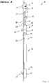
- FIG. 2 shows an enlarged detail view A, as in FIG. 1 located.
- a first secondary lock 14 and a second secondary lock 16 are shown.
- FIG. 1 can recognize the locking device 10 also above the main lock 12 via a first secondary lock 14 and a second secondary lock 16.
- the first secondary lock 14 and the second secondary lock 16 in FIG. 2 are described below the main lock 12, these statements also apply to the first secondary lock 14 and the second secondary lock 16 above the main lock 12, since these correspond in their construction and in their connection to the arranged below the main lock 12 slave locks.
- the locking device 10 has a first drive rod 22, wherein the first secondary lock 14 is coupled via the first drive rod 22 to the main lock 12.
- the locking device 10 has a second drive rod 24, wherein the second secondary lock 16 is coupled by means of the second drive rod 24 with the main lock 12.
- the main lock 12 has a pusher 26 and a lock cylinder 28.
- the main lock 12 has a latch 30 and a lock bolt 32.
- the first secondary lock 14 has a closing element 34 of a first type.
- the closing element 34 of a first type is formed in the present embodiment as a pivoting hook 34.
- An embodiment with the closing element of a first type as a bolt or locking bolt is also conceivable.
- the first secondary lock 14 is a manually operable lock which can be displaced by manual actuation, for example of the lock cylinder 28, between a closed position and an open position.
- the second secondary lock 16 has a closing element 36 of a second type.
- the closing element 36 of a second type is designed as a spring-biased latch bolt 36.
- the second secondary lock 16 is designed as an automatic lock that triggers the closing element 36 of the second type, ie the latch bolt, when closing the door or the window on which the locking device 10 is arranged, by contact with a door or window frame or a striking plate. wherein the latch bolt is displaced from a first extended position to a second, opposite the forend 20 further extended position. This is done with a normal closing of the door or window, so a "squeezing" the door or the window with the locking device 10 in the door or window frame.
- the first secondary lock 14 is coupled to the main lock 12 via the first drive rod 22.
- the second secondary lock 16 is also connected to the second drive rod 24 Main lock 12 coupled.
- the first secondary lock 14 and the second secondary lock 16 can be actuated by the main lock 12.
- the Schlossein termee the main lock 12 is formed such that the follower 26 is coupled to the second drive rod 24.
- the second drive rod can be actuated and thus the closing element 36 of a second type, ie the latch bolt 36, can be pulled into the lock housing 16 'of the second auxiliary lock 16.
- the latch 30 is coupled to the pusher nut 26, it can also be retracted into the lock housing 12 'of the main lock 12 when the door pusher 26, which is coupled to the pusher nut (not shown), is pressed down.
- the Schlossein may also be formed such that the lock cylinder 28 is coupled to the first drive rod 22.
- the closing element 34 of a first type By pressing the lock cylinder 28, thus, the closing element 34 of a first type, so the pivot hooks 34, the first secondary lock 14 are actuated.
- the closing element 34 of a first type can be pivoted into the lock housing 14 'of the first secondary lock 14.
- the closing element 34 of a first type In a precluding, ie a closing of the lock cylinder 28, the closing element 34 of a first type can be pivoted out of the lock housing 14 'of the first secondary lock 14, as in FIG. 2 shown. If the lock bolt 32 of the main lock 12 coupled to the lock cylinder 28, this can also be spent in a closed position at a Vor gleich the lock cylinder 28 in which the lock bolt 32 protrudes from the forend 20.
- the Schlossein combined with the main lock 12 can also be designed such that in the pre-closed state of the lock cylinder 28, the first drive rod and the second drive rod 24 is blocked. This not only the drive rods 22 and 24 are blocked, even pressing the pusher 26 is then no longer possible. Thus, a door opening can be prevented by the automatic opener 18, so that here is a "master control" is possible.
- the lock fitting of the main lock 12 may be configured such that the follower 26 actuates the second drive rod upon actuation in a first direction, such as depressing a door handle (not shown) coupled to the follower 26 Closing element 36 of a second type in the lock housing 16 'of the second secondary lock 16 moves and that upon actuation of the follower 26 in a second direction, such as pushing up a coupled with the pusher 26 door handle, the pusher 26, the closing element 34 of the first kind, ie the swing hook pressed.
- a first direction such as depressing a door handle (not shown) coupled to the follower 26
- Closing element 36 of a second type in the lock housing 16 'of the second secondary lock 16 moves and that upon actuation of the follower 26 in a second direction, such as pushing up a coupled with the pusher 26 door handle, the pusher 26, the closing element 34 of the first kind, ie the swing hook pressed.
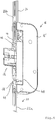
- the first drive rod 22 has a first portion 22 a and a second portion 22 b, which are coupled together by means of a connecting piece 28.
- the connecting piece 38 is guided between the second secondary lock 16 or the lock housing 16 'of the second secondary lock 16 and the forend 20.
- the connecting piece 38 and the second secondary lock 16 are enlarged in FIG FIG. 3 shown, in a disassembled state.
- the lock housing 16 'of the second secondary lock 16 has a recess 40 for receiving the Connector 38 on.
- the connecting piece 38 is in the recess 40 of the lock housing 16 'of the second secondary lock 16 in the actuating direction - in the installation situation that is the Stulplteilsplatz - slidably guided.
- the connector 38 has a passage 42 for the passage of the closing element 36 of the second secondary lock 16, namely the latch bolt 36.
- the passage 42 is dimensioned greater in height than the height of the closing element 36, so that the closing element 36, the connector 38 regardless of the Can pass through the displacement position.
- the connector 38 also has end recesses 44 for coupling to the sections 22a, 22b of the first drive rod.
- the recesses 44 have a T-shaped cross-section.
- FIG. 4 the installation situation of the connecting piece 38 and the second secondary lock 16 is shown.
- the sections 22a, 22b of the first drive rod are coupled to the connector 38, via ends 46 of T-shaped cross-section.
- the second drive rod 24 is coupled to the lock set of the second sub-lock 16.
- first secondary locks 14 with closing elements 34 of a first type and two second secondary locks 16 with closing elements 36 a second kind achieves a safe and reliable closing state of a door or a window.
- first and second secondary locks 14, 16 are operated independently.
- first and second secondary locks 14, 16 are operated independently.
- not only two different locking states can be achieved, namely a snapping the latch bolt 36 by merely "pulling" the door and a second, additionally secured locking state by the pivot hooks 34 are pivoted to a closed position and engage behind a arranged on the door frame strike plate, said an actuation by the lock cylinder 28 can take place.
- a secure closed state can also be achieved if the second secondary locks 16 are not triggered, for example as a result of manipulation in the context of a break-in attempt , Even then can be achieved by closing the pivot hook 34 of the first secondary lock 14, a secure closed state.
- the connecting piece 38 and its arrangement on the second secondary lock 16 an independent actuation of the first secondary locks 14 and the second secondary locks 16 is made possible by simple structural means.
Landscapes
- Engineering & Computer Science (AREA)
- Mechanical Engineering (AREA)
- Structural Engineering (AREA)
- Power-Operated Mechanisms For Wings (AREA)
Claims (12)
- Dispositif de verrouillage (10), en particulier dispositif de verrouillage multipoint (10), destiné à une porte ou une fenêtre, comprenant un verrou principal d'actionnement (12), au moins un premier (14) avec un élément de fermeture (34) d'un premier type et une têtière (20) de fixation, dans lequel le premier verrou secondaire (14) est couplé au verrou principal (12) et peut être actionné par l'intermédiaire du verrou principal (12), dans lequel au moins un second verrou secondaire (16) ayant un élément de fermeture (36) d'un second type est prévu, et dans lequel le second verrou secondaire (16) est couplé au verrou principal (12) et peut être actionné par le verrou secondaire (12) indépendamment du premier verrou secondaire (14), caractérisé en ce que le verrou principal (12) et le premier verrou secondaire (14) sont couplés au moyen d'une première tige de commande (22), en ce que la première tige de commande (22) comprend deux tronçons séparés (22a, 22b), qui sont couplés par l'intermédiaire d'un élément de connexion (38), et en ce que l'élément de connexion (38) présente un passage (42) pour la mise en oeuvre de l'élément de fermeture (36) du second verrou secondaire (16).
- Dispositif de verrouillage (10) selon la revendication 1, caractérisé en ce que le second verrou secondaire (16) est agencé dans la direction longitudinale de têtière entre le verrou principal (12) et le premier verrou secondaire (14).
- Dispositif de verrouillage (10) selon la revendication 1 ou 2, caractérisé en ce que le verrou principal (12) et le second verrou secondaire (16) sont couplés au moyen d'une seconde tige de commande (24).
- Dispositif de verrouillage (10) selon l'une quelconque des revendications précédentes, caractérisé en ce que l'élément de connexion (38) est guidé de manière coulissante au niveau du second verrou secondaire (16), notamment entre un boîtier de verrou (16') du second verrou secondaire (16) et la têtière (20).
- Dispositif de verrouillage (10) selon l'une quelconque des revendications précédentes, caractérisé en ce que l'élément de connexion (38) comporte des évidements d'extrémité (44) pour couplage avec les tronçons (22a, 22b) de la première tige de commande (22).
- Dispositif de verrouillage (10) selon l'une quelconque des revendications précédentes, caractérisé en ce que le verrou principal (12) comporte un fouillot (26) couplé à la seconde tige de commande (24), de sorte que le second verrou secondaire (16) peut être utilisé par l'intermédiaire du fouillot (26).
- Dispositif de verrouillage (10) selon l'une quelconque des revendications précédentes, caractérisé en ce que le verrou principal (12) comporte un cylindre de fermeture (28) qui est couplé à la première tige de commande (22), de sorte que le premier verrou secondaire (14) peut être actionnée au moyen du cylindre de fermeture (28).
- Dispositif de verrouillage (10) selon la revendication 7, caractérisé en ce que le mécanisme de verrouillage du verrou principal (12) est conçu de telle sorte qu'en position de pré-fermeture du cylindre de fermeture (28), la première tige de commande (22) et la seconde tige de commande (24) sont bloquées.
- Dispositif de verrouillage (10) selon l'une quelconque des revendications précédentes, caractérisé en ce qu'un entraînement motorisé (18) est prévu sur la têtière (20), au moyen duquel au moins une des tiges de commande (22, 24) peut être entraînée.
- Dispositif de verrouillage (10) selon l'une quelconque des revendications précédentes, caractérisé en ce que le premier verrou secondaire (14) est conçu sous la forme d'un verrou de verrouillage manuel ou non-automatique et/ou l'élément de fermeture (34) du premier type est conçu sous la forme d'un crochet pivotant (36), d'un pêne ou d'un pêne cylindrique.
- Dispositif de verrouillage (10) selon l'une quelconque des revendications précédentes, caractérisé en ce que le second verrou secondaire (16) est conçu sous la forme d'un verrou à verrouillage automatique et/ou l'élément de fermeture (36) du second type est conçu sous la forme d'un pêne demi-tour auto-verrouillant (36)
- Dispositif de verrouillage (10) selon l'une quelconque des revendications précédentes, caractérisé en ce que le verrou principal (12) comporte un bec-de-cane (30) et/ou un pêne dormant (32).
Priority Applications (1)
| Application Number | Priority Date | Filing Date | Title |
|---|---|---|---|
| EP15159130.2A EP3070238B1 (fr) | 2015-03-16 | 2015-03-16 | Dispositif de verrouillage pour une porte ou une fenêtre |
Applications Claiming Priority (1)
| Application Number | Priority Date | Filing Date | Title |
|---|---|---|---|
| EP15159130.2A EP3070238B1 (fr) | 2015-03-16 | 2015-03-16 | Dispositif de verrouillage pour une porte ou une fenêtre |
Publications (2)
| Publication Number | Publication Date |
|---|---|
| EP3070238A1 EP3070238A1 (fr) | 2016-09-21 |
| EP3070238B1 true EP3070238B1 (fr) | 2018-08-22 |
Family
ID=52672200
Family Applications (1)
| Application Number | Title | Priority Date | Filing Date |
|---|---|---|---|
| EP15159130.2A Active EP3070238B1 (fr) | 2015-03-16 | 2015-03-16 | Dispositif de verrouillage pour une porte ou une fenêtre |
Country Status (1)
| Country | Link |
|---|---|
| EP (1) | EP3070238B1 (fr) |
Families Citing this family (4)
| Publication number | Priority date | Publication date | Assignee | Title |
|---|---|---|---|---|
| EP3348756B1 (fr) * | 2017-01-12 | 2019-03-06 | Gretsch-Unitas GmbH Baubeschläge | Dispositif de fermeture de porte, fenêtre ou analogue |
| GB201707144D0 (en) | 2017-05-04 | 2017-06-21 | Era Home Security Ltd | Locking assembly |
| CN108678648A (zh) * | 2018-07-31 | 2018-10-19 | 吴端龙 | 一种分体式地钩锁 |
| PL4215702T3 (pl) | 2022-01-21 | 2024-05-06 | Gretsch-Unitas GmbH Baubeschläge | Urządzenie ryglujące |
Citations (12)
| Publication number | Priority date | Publication date | Assignee | Title |
|---|---|---|---|---|
| DE2515990A1 (de) * | 1975-04-12 | 1976-10-21 | Stucke Lothar | Laengenverstellbare kupplungsvorrichtung |
| DE8413327U1 (fr) | 1984-05-02 | 1987-03-26 | Carl Fuhr Gmbh & Co, 5628 Heiligenhaus, De | |
| GB2225052A (en) | 1988-10-25 | 1990-05-23 | Bayley Bryan | Locking mechanism |
| DE4015880A1 (de) | 1990-05-17 | 1991-11-28 | Karrenberg Fa Wilhelm | Treibstangenschloss |
| DE19522641A1 (de) | 1995-06-22 | 1997-01-02 | Winkhaus Fa August | Schließeinrichtung mit Flügelfangeinrichtung |
| EP0798436A2 (fr) | 1996-03-26 | 1997-10-01 | Gretsch-Unitas GmbH Baubeschläge | Dispositif de verrouillage |
| DE29802967U1 (de) | 1998-02-23 | 1999-07-22 | Gretsch Unitas Gmbh | Schloß, insbesondere Einsteckschloß |
| DE19815671A1 (de) | 1998-04-08 | 1999-10-14 | Wilka Schliestechnik Gmbh | Treibstangenverschluß |
| DE20008856U1 (de) * | 2000-05-18 | 2000-07-27 | Winkhaus Fa August | Treibstangenbeschlag-System mit Hochkant-Treibstange und Verzahnungsverbindungseinheit |
| EP1219768A2 (fr) | 2000-12-13 | 2002-07-03 | Euroinvest S.r.L. | Dispositif de jonction mécanique pour un dispositif de verrouillage périphérique en profilés métalliques pour porte et fenêtre à l'épreuve de l'effraction |
| EP2246508A2 (fr) | 2009-04-22 | 2010-11-03 | KFV Karl Fliether GmbH & Co. KG | Crémone avec pêne demi-tour et verrou à coulisse |
| EP2592205A2 (fr) | 2011-11-11 | 2013-05-15 | Assa Abloy Limited | Ensembles de verrouillage |
Family Cites Families (2)
| Publication number | Priority date | Publication date | Assignee | Title |
|---|---|---|---|---|
| DE3901223A1 (de) * | 1988-01-18 | 1989-08-03 | Winkhaus Fa August | Treibstangenschloss |
| DE202013009209U1 (de) | 2013-10-18 | 2013-11-06 | Kfv Karl Fliether Gmbh & Co. Kg | Verriegelungseinrichtung |
-
2015
- 2015-03-16 EP EP15159130.2A patent/EP3070238B1/fr active Active
Patent Citations (12)
| Publication number | Priority date | Publication date | Assignee | Title |
|---|---|---|---|---|
| DE2515990A1 (de) * | 1975-04-12 | 1976-10-21 | Stucke Lothar | Laengenverstellbare kupplungsvorrichtung |
| DE8413327U1 (fr) | 1984-05-02 | 1987-03-26 | Carl Fuhr Gmbh & Co, 5628 Heiligenhaus, De | |
| GB2225052A (en) | 1988-10-25 | 1990-05-23 | Bayley Bryan | Locking mechanism |
| DE4015880A1 (de) | 1990-05-17 | 1991-11-28 | Karrenberg Fa Wilhelm | Treibstangenschloss |
| DE19522641A1 (de) | 1995-06-22 | 1997-01-02 | Winkhaus Fa August | Schließeinrichtung mit Flügelfangeinrichtung |
| EP0798436A2 (fr) | 1996-03-26 | 1997-10-01 | Gretsch-Unitas GmbH Baubeschläge | Dispositif de verrouillage |
| DE29802967U1 (de) | 1998-02-23 | 1999-07-22 | Gretsch Unitas Gmbh | Schloß, insbesondere Einsteckschloß |
| DE19815671A1 (de) | 1998-04-08 | 1999-10-14 | Wilka Schliestechnik Gmbh | Treibstangenverschluß |
| DE20008856U1 (de) * | 2000-05-18 | 2000-07-27 | Winkhaus Fa August | Treibstangenbeschlag-System mit Hochkant-Treibstange und Verzahnungsverbindungseinheit |
| EP1219768A2 (fr) | 2000-12-13 | 2002-07-03 | Euroinvest S.r.L. | Dispositif de jonction mécanique pour un dispositif de verrouillage périphérique en profilés métalliques pour porte et fenêtre à l'épreuve de l'effraction |
| EP2246508A2 (fr) | 2009-04-22 | 2010-11-03 | KFV Karl Fliether GmbH & Co. KG | Crémone avec pêne demi-tour et verrou à coulisse |
| EP2592205A2 (fr) | 2011-11-11 | 2013-05-15 | Assa Abloy Limited | Ensembles de verrouillage |
Also Published As
| Publication number | Publication date |
|---|---|
| EP3070238A1 (fr) | 2016-09-21 |
Similar Documents
| Publication | Publication Date | Title |
|---|---|---|
| EP1932989B1 (fr) | Système de fermeture pour portes, fenêtres ou analogues, en particulier crémone-serrure à fonction d'urgence et de verrouillage à plusieurs points | |
| DE2611359C2 (de) | Treibstangenverschluß für Türflügel | |
| EP2951369B1 (fr) | Serrure anti-panique | |
| DE3844849C2 (de) | Treibstangenverschluß | |
| EP2673435B1 (fr) | Système de serrure pour bloc-porte à deux vantaux à fonction anti-panique | |
| EP0945572B1 (fr) | Ensemble de serrure de porte, de préférence crémone-serrure | |
| EP3070238B1 (fr) | Dispositif de verrouillage pour une porte ou une fenêtre | |
| DE19514742A1 (de) | Rohrrahmenschloß | |
| DE4114007C2 (de) | Treibstangenverschluß | |
| DE102015000606A1 (de) | Verriegelungsvorrichtung für einen schwenkbar gelagerten Flügel | |
| EP2339096B1 (fr) | Serrure à crémone dotée d'une fonction anti-panique et d'un verrouillage multiple | |
| EP3907357A1 (fr) | Dispositif de verrouillage | |
| EP2752539B2 (fr) | Crémone espagnolette | |
| DE3831529C2 (de) | Treibstangenverschluß | |
| EP3628801B1 (fr) | Dispositif de fermeture pour une porte et procédé pour ouvrir une porte | |
| DE3931101A1 (de) | Automatisch verriegelndes schloss | |
| EP0439478B1 (fr) | Serrure a verrouillage automatique | |
| EP2322744B1 (fr) | Serrure, serrure à crochet pivotant et système de verrouillage, notamment pour le verrouillage à plusieurs points d'une porte ou d'une fenêtre | |
| EP3216952B1 (fr) | Dispositif de verrouillage | |
| EP1030018B1 (fr) | Dispositif d'entrebâillement pour porte | |
| DE102020205673B3 (de) | Selbstverriegelndes Schloss | |
| DE19828365C1 (de) | Schloß für schall- und/oder wärmedämmende Türen | |
| EP3363970B1 (fr) | Serrure | |
| EP2998475B1 (fr) | Levier de jour pour une serrure a battant passif | |
| AT514537B1 (de) | Sicherheitstür-Zarge-Kombination |
Legal Events
| Date | Code | Title | Description |
|---|---|---|---|
| PUAI | Public reference made under article 153(3) epc to a published international application that has entered the european phase |
Free format text: ORIGINAL CODE: 0009012 |
|
| 17P | Request for examination filed |
Effective date: 20151208 |
|
| AK | Designated contracting states |
Kind code of ref document: A1 Designated state(s): AL AT BE BG CH CY CZ DE DK EE ES FI FR GB GR HR HU IE IS IT LI LT LU LV MC MK MT NL NO PL PT RO RS SE SI SK SM TR |
|
| AX | Request for extension of the european patent |
Extension state: BA ME |
|
| STAA | Information on the status of an ep patent application or granted ep patent |
Free format text: STATUS: EXAMINATION IS IN PROGRESS |
|
| 17Q | First examination report despatched |
Effective date: 20180208 |
|
| GRAP | Despatch of communication of intention to grant a patent |
Free format text: ORIGINAL CODE: EPIDOSNIGR1 |
|
| STAA | Information on the status of an ep patent application or granted ep patent |
Free format text: STATUS: GRANT OF PATENT IS INTENDED |
|
| INTG | Intention to grant announced |
Effective date: 20180404 |
|
| RIN1 | Information on inventor provided before grant (corrected) |
Inventor name: HERTLE, THOMAS |
|
| GRAS | Grant fee paid |
Free format text: ORIGINAL CODE: EPIDOSNIGR3 |
|
| GRAA | (expected) grant |
Free format text: ORIGINAL CODE: 0009210 |
|
| STAA | Information on the status of an ep patent application or granted ep patent |
Free format text: STATUS: THE PATENT HAS BEEN GRANTED |
|
| AK | Designated contracting states |
Kind code of ref document: B1 Designated state(s): AL AT BE BG CH CY CZ DE DK EE ES FI FR GB GR HR HU IE IS IT LI LT LU LV MC MK MT NL NO PL PT RO RS SE SI SK SM TR |
|
| REG | Reference to a national code |
Ref country code: GB Ref legal event code: FG4D Free format text: NOT ENGLISH |
|
| REG | Reference to a national code |
Ref country code: CH Ref legal event code: EP |
|
| REG | Reference to a national code |
Ref country code: AT Ref legal event code: REF Ref document number: 1032720 Country of ref document: AT Kind code of ref document: T Effective date: 20180915 |
|
| REG | Reference to a national code |
Ref country code: IE Ref legal event code: FG4D Free format text: LANGUAGE OF EP DOCUMENT: GERMAN |
|
| REG | Reference to a national code |
Ref country code: DE Ref legal event code: R096 Ref document number: 502015005527 Country of ref document: DE |
|
| REG | Reference to a national code |
Ref country code: NL Ref legal event code: FP |
|
| REG | Reference to a national code |
Ref country code: LT Ref legal event code: MG4D |
|
| PG25 | Lapsed in a contracting state [announced via postgrant information from national office to epo] |
Ref country code: GR Free format text: LAPSE BECAUSE OF FAILURE TO SUBMIT A TRANSLATION OF THE DESCRIPTION OR TO PAY THE FEE WITHIN THE PRESCRIBED TIME-LIMIT Effective date: 20181123 Ref country code: NO Free format text: LAPSE BECAUSE OF FAILURE TO SUBMIT A TRANSLATION OF THE DESCRIPTION OR TO PAY THE FEE WITHIN THE PRESCRIBED TIME-LIMIT Effective date: 20181122 Ref country code: BG Free format text: LAPSE BECAUSE OF FAILURE TO SUBMIT A TRANSLATION OF THE DESCRIPTION OR TO PAY THE FEE WITHIN THE PRESCRIBED TIME-LIMIT Effective date: 20181122 Ref country code: SE Free format text: LAPSE BECAUSE OF FAILURE TO SUBMIT A TRANSLATION OF THE DESCRIPTION OR TO PAY THE FEE WITHIN THE PRESCRIBED TIME-LIMIT Effective date: 20180822 Ref country code: LT Free format text: LAPSE BECAUSE OF FAILURE TO SUBMIT A TRANSLATION OF THE DESCRIPTION OR TO PAY THE FEE WITHIN THE PRESCRIBED TIME-LIMIT Effective date: 20180822 Ref country code: FI Free format text: LAPSE BECAUSE OF FAILURE TO SUBMIT A TRANSLATION OF THE DESCRIPTION OR TO PAY THE FEE WITHIN THE PRESCRIBED TIME-LIMIT Effective date: 20180822 Ref country code: IS Free format text: LAPSE BECAUSE OF FAILURE TO SUBMIT A TRANSLATION OF THE DESCRIPTION OR TO PAY THE FEE WITHIN THE PRESCRIBED TIME-LIMIT Effective date: 20181222 Ref country code: RS Free format text: LAPSE BECAUSE OF FAILURE TO SUBMIT A TRANSLATION OF THE DESCRIPTION OR TO PAY THE FEE WITHIN THE PRESCRIBED TIME-LIMIT Effective date: 20180822 |
|
| PG25 | Lapsed in a contracting state [announced via postgrant information from national office to epo] |
Ref country code: HR Free format text: LAPSE BECAUSE OF FAILURE TO SUBMIT A TRANSLATION OF THE DESCRIPTION OR TO PAY THE FEE WITHIN THE PRESCRIBED TIME-LIMIT Effective date: 20180822 Ref country code: LV Free format text: LAPSE BECAUSE OF FAILURE TO SUBMIT A TRANSLATION OF THE DESCRIPTION OR TO PAY THE FEE WITHIN THE PRESCRIBED TIME-LIMIT Effective date: 20180822 Ref country code: AL Free format text: LAPSE BECAUSE OF FAILURE TO SUBMIT A TRANSLATION OF THE DESCRIPTION OR TO PAY THE FEE WITHIN THE PRESCRIBED TIME-LIMIT Effective date: 20180822 |
|
| PG25 | Lapsed in a contracting state [announced via postgrant information from national office to epo] |
Ref country code: EE Free format text: LAPSE BECAUSE OF FAILURE TO SUBMIT A TRANSLATION OF THE DESCRIPTION OR TO PAY THE FEE WITHIN THE PRESCRIBED TIME-LIMIT Effective date: 20180822 Ref country code: IT Free format text: LAPSE BECAUSE OF FAILURE TO SUBMIT A TRANSLATION OF THE DESCRIPTION OR TO PAY THE FEE WITHIN THE PRESCRIBED TIME-LIMIT Effective date: 20180822 Ref country code: RO Free format text: LAPSE BECAUSE OF FAILURE TO SUBMIT A TRANSLATION OF THE DESCRIPTION OR TO PAY THE FEE WITHIN THE PRESCRIBED TIME-LIMIT Effective date: 20180822 Ref country code: CZ Free format text: LAPSE BECAUSE OF FAILURE TO SUBMIT A TRANSLATION OF THE DESCRIPTION OR TO PAY THE FEE WITHIN THE PRESCRIBED TIME-LIMIT Effective date: 20180822 Ref country code: ES Free format text: LAPSE BECAUSE OF FAILURE TO SUBMIT A TRANSLATION OF THE DESCRIPTION OR TO PAY THE FEE WITHIN THE PRESCRIBED TIME-LIMIT Effective date: 20180822 Ref country code: PL Free format text: LAPSE BECAUSE OF FAILURE TO SUBMIT A TRANSLATION OF THE DESCRIPTION OR TO PAY THE FEE WITHIN THE PRESCRIBED TIME-LIMIT Effective date: 20180822 |
|
| REG | Reference to a national code |
Ref country code: DE Ref legal event code: R026 Ref document number: 502015005527 Country of ref document: DE |
|
| PLBI | Opposition filed |
Free format text: ORIGINAL CODE: 0009260 |
|
| PG25 | Lapsed in a contracting state [announced via postgrant information from national office to epo] |
Ref country code: SK Free format text: LAPSE BECAUSE OF FAILURE TO SUBMIT A TRANSLATION OF THE DESCRIPTION OR TO PAY THE FEE WITHIN THE PRESCRIBED TIME-LIMIT Effective date: 20180822 Ref country code: SM Free format text: LAPSE BECAUSE OF FAILURE TO SUBMIT A TRANSLATION OF THE DESCRIPTION OR TO PAY THE FEE WITHIN THE PRESCRIBED TIME-LIMIT Effective date: 20180822 Ref country code: DK Free format text: LAPSE BECAUSE OF FAILURE TO SUBMIT A TRANSLATION OF THE DESCRIPTION OR TO PAY THE FEE WITHIN THE PRESCRIBED TIME-LIMIT Effective date: 20180822 |
|
| PLAX | Notice of opposition and request to file observation + time limit sent |
Free format text: ORIGINAL CODE: EPIDOSNOBS2 |
|
| 26 | Opposition filed |
Opponent name: GEZE GMBH Effective date: 20190522 |
|
| PG25 | Lapsed in a contracting state [announced via postgrant information from national office to epo] |
Ref country code: SI Free format text: LAPSE BECAUSE OF FAILURE TO SUBMIT A TRANSLATION OF THE DESCRIPTION OR TO PAY THE FEE WITHIN THE PRESCRIBED TIME-LIMIT Effective date: 20180822 |
|
| PLBB | Reply of patent proprietor to notice(s) of opposition received |
Free format text: ORIGINAL CODE: EPIDOSNOBS3 |
|
| PG25 | Lapsed in a contracting state [announced via postgrant information from national office to epo] |
Ref country code: MC Free format text: LAPSE BECAUSE OF FAILURE TO SUBMIT A TRANSLATION OF THE DESCRIPTION OR TO PAY THE FEE WITHIN THE PRESCRIBED TIME-LIMIT Effective date: 20180822 |
|
| REG | Reference to a national code |
Ref country code: CH Ref legal event code: PL |
|
| GBPC | Gb: european patent ceased through non-payment of renewal fee |
Effective date: 20190316 |
|
| PG25 | Lapsed in a contracting state [announced via postgrant information from national office to epo] |
Ref country code: LU Free format text: LAPSE BECAUSE OF NON-PAYMENT OF DUE FEES Effective date: 20190316 |
|
| REG | Reference to a national code |
Ref country code: BE Ref legal event code: MM Effective date: 20190331 |
|
| PG25 | Lapsed in a contracting state [announced via postgrant information from national office to epo] |
Ref country code: GB Free format text: LAPSE BECAUSE OF NON-PAYMENT OF DUE FEES Effective date: 20190316 Ref country code: IE Free format text: LAPSE BECAUSE OF NON-PAYMENT OF DUE FEES Effective date: 20190316 Ref country code: CH Free format text: LAPSE BECAUSE OF NON-PAYMENT OF DUE FEES Effective date: 20190331 Ref country code: LI Free format text: LAPSE BECAUSE OF NON-PAYMENT OF DUE FEES Effective date: 20190331 |
|
| PG25 | Lapsed in a contracting state [announced via postgrant information from national office to epo] |
Ref country code: BE Free format text: LAPSE BECAUSE OF NON-PAYMENT OF DUE FEES Effective date: 20190331 |
|
| PG25 | Lapsed in a contracting state [announced via postgrant information from national office to epo] |
Ref country code: TR Free format text: LAPSE BECAUSE OF FAILURE TO SUBMIT A TRANSLATION OF THE DESCRIPTION OR TO PAY THE FEE WITHIN THE PRESCRIBED TIME-LIMIT Effective date: 20180822 |
|
| PG25 | Lapsed in a contracting state [announced via postgrant information from national office to epo] |
Ref country code: MT Free format text: LAPSE BECAUSE OF FAILURE TO SUBMIT A TRANSLATION OF THE DESCRIPTION OR TO PAY THE FEE WITHIN THE PRESCRIBED TIME-LIMIT Effective date: 20180822 Ref country code: PT Free format text: LAPSE BECAUSE OF FAILURE TO SUBMIT A TRANSLATION OF THE DESCRIPTION OR TO PAY THE FEE WITHIN THE PRESCRIBED TIME-LIMIT Effective date: 20181222 |
|
| REG | Reference to a national code |
Ref country code: AT Ref legal event code: MM01 Ref document number: 1032720 Country of ref document: AT Kind code of ref document: T Effective date: 20200316 |
|
| PG25 | Lapsed in a contracting state [announced via postgrant information from national office to epo] |
Ref country code: CY Free format text: LAPSE BECAUSE OF FAILURE TO SUBMIT A TRANSLATION OF THE DESCRIPTION OR TO PAY THE FEE WITHIN THE PRESCRIBED TIME-LIMIT Effective date: 20180822 |
|
| PG25 | Lapsed in a contracting state [announced via postgrant information from national office to epo] |
Ref country code: HU Free format text: LAPSE BECAUSE OF FAILURE TO SUBMIT A TRANSLATION OF THE DESCRIPTION OR TO PAY THE FEE WITHIN THE PRESCRIBED TIME-LIMIT; INVALID AB INITIO Effective date: 20150316 |
|
| PG25 | Lapsed in a contracting state [announced via postgrant information from national office to epo] |
Ref country code: AT Free format text: LAPSE BECAUSE OF NON-PAYMENT OF DUE FEES Effective date: 20200316 |
|
| REG | Reference to a national code |
Ref country code: DE Ref legal event code: R100 Ref document number: 502015005527 Country of ref document: DE |
|
| PLCK | Communication despatched that opposition was rejected |
Free format text: ORIGINAL CODE: EPIDOSNREJ1 |
|
| PLBN | Opposition rejected |
Free format text: ORIGINAL CODE: 0009273 |
|
| STAA | Information on the status of an ep patent application or granted ep patent |
Free format text: STATUS: OPPOSITION REJECTED |
|
| 27O | Opposition rejected |
Effective date: 20211005 |
|
| REG | Reference to a national code |
Ref country code: DE Ref legal event code: R082 Ref document number: 502015005527 Country of ref document: DE |
|
| PG25 | Lapsed in a contracting state [announced via postgrant information from national office to epo] |
Ref country code: MK Free format text: LAPSE BECAUSE OF FAILURE TO SUBMIT A TRANSLATION OF THE DESCRIPTION OR TO PAY THE FEE WITHIN THE PRESCRIBED TIME-LIMIT Effective date: 20180822 |
|
| PGFP | Annual fee paid to national office [announced via postgrant information from national office to epo] |
Ref country code: FR Payment date: 20230324 Year of fee payment: 9 |
|
| P01 | Opt-out of the competence of the unified patent court (upc) registered |
Effective date: 20230509 |
|
| PGFP | Annual fee paid to national office [announced via postgrant information from national office to epo] |
Ref country code: NL Payment date: 20240320 Year of fee payment: 10 |
|
| PGFP | Annual fee paid to national office [announced via postgrant information from national office to epo] |
Ref country code: DE Payment date: 20240320 Year of fee payment: 10 |