EP2244013A1 - Einen brenner bildender und einsetzender mischzyklon und den brenner verwendendes verbrennungsverfahren - Google Patents
Einen brenner bildender und einsetzender mischzyklon und den brenner verwendendes verbrennungsverfahren Download PDFInfo
- Publication number
- EP2244013A1 EP2244013A1 EP08734204A EP08734204A EP2244013A1 EP 2244013 A1 EP2244013 A1 EP 2244013A1 EP 08734204 A EP08734204 A EP 08734204A EP 08734204 A EP08734204 A EP 08734204A EP 2244013 A1 EP2244013 A1 EP 2244013A1
- Authority
- EP
- European Patent Office
- Prior art keywords
- gas
- flow
- air
- characteristic
- box
- Prior art date
- Legal status (The legal status is an assumption and is not a legal conclusion. Google has not performed a legal analysis and makes no representation as to the accuracy of the status listed.)
- Granted
Links
Images

Classifications
-
- F—MECHANICAL ENGINEERING; LIGHTING; HEATING; WEAPONS; BLASTING
- F23—COMBUSTION APPARATUS; COMBUSTION PROCESSES
- F23D—BURNERS
- F23D14/00—Burners for combustion of a gas, e.g. of a gas stored under pressure as a liquid
- F23D14/02—Premix gas burners, i.e. in which gaseous fuel is mixed with combustion air upstream of the combustion zone
-
- F—MECHANICAL ENGINEERING; LIGHTING; HEATING; WEAPONS; BLASTING
- F23—COMBUSTION APPARATUS; COMBUSTION PROCESSES
- F23D—BURNERS
- F23D14/00—Burners for combustion of a gas, e.g. of a gas stored under pressure as a liquid
- F23D14/46—Details
- F23D14/62—Mixing devices; Mixing tubes
-
- F—MECHANICAL ENGINEERING; LIGHTING; HEATING; WEAPONS; BLASTING
- F23—COMBUSTION APPARATUS; COMBUSTION PROCESSES
- F23D—BURNERS
- F23D3/00—Burners using capillary action
- F23D3/02—Wick burners
- F23D3/08—Wick burners characterised by shape, construction, or material, of wick
-
- F—MECHANICAL ENGINEERING; LIGHTING; HEATING; WEAPONS; BLASTING
- F24—HEATING; RANGES; VENTILATING
- F24C—DOMESTIC STOVES OR RANGES ; DETAILS OF DOMESTIC STOVES OR RANGES, OF GENERAL APPLICATION
- F24C3/00—Stoves or ranges for gaseous fuels
- F24C3/08—Arrangement or mounting of burners
-
- F—MECHANICAL ENGINEERING; LIGHTING; HEATING; WEAPONS; BLASTING
- F24—HEATING; RANGES; VENTILATING
- F24C—DOMESTIC STOVES OR RANGES ; DETAILS OF DOMESTIC STOVES OR RANGES, OF GENERAL APPLICATION
- F24C7/00—Stoves or ranges heated by electric energy
- F24C7/002—Stoves
-
- F—MECHANICAL ENGINEERING; LIGHTING; HEATING; WEAPONS; BLASTING
- F23—COMBUSTION APPARATUS; COMBUSTION PROCESSES
- F23D—BURNERS
- F23D2900/00—Special features of, or arrangements for burners using fluid fuels or solid fuels suspended in a carrier gas
- F23D2900/14—Special features of gas burners
- F23D2900/14021—Premixing burners with swirling or vortices creating means for fuel or air
Definitions
- the present invention relates to combustion technology, and more specifically, relates to a method of generating mixed whirling flow, a burner applying such a method, and a combustion method of the energy-efficient burner, which may be used in canteens or kitchens of some guesthouses, hotels, institutions and schools etc.
- the present invention provides a method of generating mixed whirling flow which is capable of mixing fuel gas and air more sufficiently.
- the present invention provides a burner which is capable of mixing fuel gas and air more sufficiently, and a combustion method thereof.
- a method of generating mixed whirling flow comprising the following steps:
- step S1 further comprises the following steps:
- a burner comprising:
- said mixing device comprises a top lid and a mixing box to compose a first mixing device and a second mixing device, wherein said top lid is in a shape of sleeve.
- air from the gas-separating box is formed into a rotating airflow inclined upwardly by said first mixing device, and said second mixing device mixes the rotating airflow from the first mixing device and fuel gas from the gas-separating box into a mixed whirling flow.
- said mixing box is a box having a countersunk hole communicated with said centric hole, on the side wall of the box several grooves are disposed at a distance from each other, whose amount and position are corresponding to that of the fuel gas outlets, and a plurality of first outlets are evenly distributed on the top surface of the gas-separating box.
- air and fuel gas from the gas-separating box are firstly mixed into a rotating mixed flow inclined upwardly by the first mixing device, and the rotating mixed flow from the first mixing device is formed into a mixed whirling flow by the second mixing device.
- said gas-separating box has a centric hole through which air enters and at least one inlet through which fuel gas enters, and on the top surface of the gas-separating box, several fuel gas outlets are provided.
- said mixing box is a box having a countersunk hole communicated with said centric hole, on the side wall of the box several grooves are disposed at a distance from each other, whose amount and position are corresponding to that of the fuel gas outlets, and communicating holes are disposed on the surface of the grooves, communicating with air in said countersunk hole, and the grooves mix air and fuel gas primarily to form a rotating mixed flow inclined upwardly.
- said grooves are inclined upwards.
- an angle between said grooves and the bottom surface of the mixing box is 10 to 80 degree.
- said grooves are at least 50mm long.
- cross section of said grooves is in a shape of square or inverted trapezoidal.
- the flame hole on the top lid for the mixed flow to rush out has a frustoconic surface, which makes the whirly mixed flow be reflected onto a reflecting plate on the mixing box and then rush out of the flame hole to form a mixed whirling flow with a tiny bottom but a big top end.
- size of the flame hole is one fifth to one third the size of the top lid.
- the fuel gas outlets are evenly distributed, while the communicating holes are evenly distributed too.
- diameter of the fuel gas outlets and the communicating holes are 0.5 to 3mm.
- a mounting throughhole is arranged on the top surface of said mixing box, said mounting throughhole is provided with a insulating sleeve which comprises a round plate mounted within the countersunk hole and a ring matched with the mounting throughhole, on the insulating sleeve a reflecting plate is arranged, which is connected with a zero wire of a ion flame controller, and said mixing box has two pulse ignition rods.
- a combustion method of the burner in accordance with embodiments of the present invention comprising the following steps:
- the burner in accordance with the present invention comprises a sleeve-type top lid, a gas-separating box is connected to the bottom of the top lid, and a space is formed between the top lid and the gas-separating box, in which a device for air dispersion and fuel gas mixing is disposed;
- the gas-separating box has a centric hole through which air enters and at least one inlet through fuel gas enters, on the top surface of the gas-separating box several fuel gas outlets are provided;
- said device for air dispersion and fuel gas mixing is a box having a countersunk hole communicated with the centric hole, on the side wall of the box several grooves are disposed at a distance from each other, whose amount and position are corresponding to that of the fuel gas outlets, and communicating holes are disposed on the surface of the grooves, communicating with air in said countersunk hole, and the grooves mix air and fuel gas primarily;
- said top lid has a frustoconic flame hole used to burn the fuel gas and reflect the mixed gas, the
- Such a structure promotes the dispersed fuel gas and air to be sufficiently mixed up in the grooves of the gas mixing device and then flow inclined upwards to the second mixing chamber and the frustoconic flame hole, the inclined frustoconic surface of the flame hole reflects the mixed gas onto the reflecting plate and then to flame hole, and finally a flame like a hurricane with a small bottom but a large top end is produced.
- a flame can be better concentrated and condensed to burn sufficiently outside the top lid with no or less heat conduction with the top lid, and the flame is not extinguished easily and generates less carbon monoxide.
- the combustion can be done in a reduced space due to the concentration and condensation of the flame, thus the volume of the whole chamber, and in turn the volume of the burner correspondingly is reduced.
- the ion flame detector does not use a ion detecting pin to detect the flame, but the zero wire of the ion flame detector is connected to the insulated reflecting plate.
- the detection can be achieved by wire connection of the ion detecting pin to a metal piece of the burner.
- the burning of the flame produces ions, the flame terminal is zero while the combust flame is positive (i.e., when the zero wire of the ion flame detector is connected to the insulated reflecting plate, then the ion detecting pin is wired to the metal piece of the burner, then the metal induces the positive ions produced by the combust flame burning the metal, thereby the ion flame detector detects that the burner is on fire.).
- the present invention provides a method of generating mixed whirling flow through mixing of air and fuel gas, comprising the following steps:
- the embodiment 1 comprises a overall process of generating the whirling mixed flow, while the embodiment 2 comprises step S1 and S2, but step S1 does not comprise step S11 and S12. More details will be described referring to the drawings.
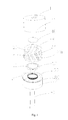
- the burner of the present invention comprises a gas-separating box 30 used to import fuel gas and air respectively, a mixing device used to mix air and fuel gas from the gas-separating box to form mixed whirling flow, and a third mixing device used to reflect the mixed whirling flow so that it rushes out of a flame hole 11 and then forms a mixed upward whirling flow with a tiny bottom but a big top end, wherein the mixing device comprises a sleeve-type top lid 10 and a mixing box 20 to compose a first mixing device and a second mixing device.
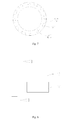
- the gas-separating box 30 is a round ring, comprises a centric hole 31 and a box body, wherein the box body is a cylinder, has several fuel gas outlets 37 positioned along a circumference on the top surface to disperse fuel gas, and a fuel gas inlet 32 through which fuel gas enters is provided on the bottom surface of the box body.
- the centric hole 31 is round with its outer portion as a ring, while the top 39 of said ring is higher than the top surface of the box body, and has external threads on it.
- the outer portion of the centric hole 31 together with the box body compose a gas-dispersing chamber 38 in a shape of cylinder. In order to disperse fuel gas completely, the fuel gas outlets 37 can be evenly distributed.
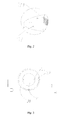
- the mixing box 20 is a cylinder, and has a countersunk hole 25 communicated with the centric hole 31. On the top of countersunk hole 25 there is a round mounting hole 29.
- a insulating sleeve 50 arranged on the mounting hole 29 comprises a round plate mounted in the countersunk hole 25 and a round ring 51 matched with the mounting hole 29.
- a reflecting plate 40 is provided on the insulating sleeve 50, which is connected to the zero wire of the ion flame controller.
- On the outer surface of the cylinder are positioned several inclined upward projections 22 and grooves 21 spaced with each other. The inclined angle of the projections 22 and the grooves 21 can be 10 to 80 degree.
- each grooves 21 are several communicating holes 210 communicated with the countersunk hole 25, and the communicating holes 210 can be 0.5 to 3mm in diameter.
- Cross section of the grooves 21 can be square or inverted trapezoidal.
- the length of the grooves 21 is no less than 50mm, and the communicating holes 210 can be evenly distributed on the grooves 21.
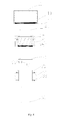
- the top lid 10 and the top surface of the mixing box 20 compose the second mixing chamber 100 for rotating the mixed gas to form a mixed whirling flow.
- the top lid 10 comprises a frustoconic flame hole 11 through which the mixed flow rushes out.
- the inclined frustoconic surface of the flame hole 11 reflects the mixed whirling flow onto the reflecting plate 40 of the mixing box 20, then the mixed whirling flow rushes out of the flame hole 11 and form a rotating mixed gas flow with a tiny bottom but a bid top end.
- an ion flame detector is applied.
- Accessories of the ion flame detector comprise an insulating sleeve 50 and a reflecting plate 40, wherein the insulating sleeve 50 is made of glass fiber, comprises a round ring 51 mounted onto a round plate, and the reflecting plate 40 is a round plate made of metal.
- the top lid 10 comprises a circular wall and a top cap on the circular wall, while a frustoconic flame hole 11 is provided on the top cap.
- size of the top surface of the flame hole 11 is selected as one fifth to one third of the size of the top cap.
- two pulse ignition devices 60 are arranged in the burner of the present invention.
- the top lid 10 In order to connect the top lid 10 and the gas-separating box 30 together, the top lid is provided with internal thread 12, while the gas-separating box 30 is provided with corresponding external thread 380 on its outer surface.
- engaged threads 250 and 35 are arranged on the inner wall of countersunk hole 25 of the mixing box 20 and on the outer ring of the centric hole 31 of the gas-separating box 30, respectively.
- the work process of the burner in the present invention is as follows:
- the swirly mixed flow and the rotating mixed flow collide with each other and flow around.
- the mixed flow is reflected onto the reflecting plate due to the frustoconic surface of the flame hole 11 and then rush out of the flame hole 11 to form a whirling mixed flow with a tiny bottom and a large top end, which produces a flame looked like hurricane with a small bottom but large head when ignited.
- a flame can be better concentrated and condensed to burn sufficiently outside the top lid with no or less heat conduction with the top lid, and the flame is not extinguished easily and generates less carbon monoxide.
- the concentration and condensation of the flame reduce the length of the flame, which will help the heat to stay rather than loss, and help the flame to be combust in a small space.
- Short flame also decrease contact of the flame with the outer air, which can reduce the heat loss, reduce the volume of the burner chamber and in turn reduce the volume of the top lid.
- the grooves 21 can be made to be at an angle of 80 or even 90 degree with the bottom surface of the mixing box 30, which will contribute sufficient mixing of the mixed gas reflected by the frustoconic surface of the flame hole 11, while fuel gas with high density such as that in present invention can be reflected by the frustoconic surface after two mixing processes.
- a fan can be used to control the input of air in the centric hole 31 to ensure that there is enough air to mix with fuel gas, thereby production of carbon monoxide as burning is reduced to achieve an effect of energy saving and environment protection.
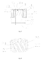
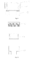
- Figs.8 to 11 show the second embodiment of the present invention, wherein the difference between the first and the second embodiments is: on the top surface of the mixing box 20 are several first outlets 300 evenly distributed along its circumference, while there is no communicating holes 210 between the countersunk hole 25 and the grooves 21. Air enters into the fuel gas outlet 37 from the gas-separating box 30 and into the grooves 21 and then flows upwardly, then forms a rotating air flow. The fuel gas enters into the second mixing chamber 100 through the first outlets 300 evenly distributed on the top surface of the mixing box 20, and then mix with the rotating air flow to form a swirly mixed flow. The swirly mixed flow and the rotating mixed flow collide with each other and flow around.
- the mixed flow can be reflected onto the reflecting plate and then rushes up to the flame hole to form a whirling mixed gas flow with a tiny bottom but big top end, which when ignited produces a flame like a hurricane which also has a tiny bottom but a big top end.
- the other aspects are the same as that of the first embodiment, so details are omitted.
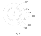
- Fig.12 shows the third embodiment of this invention which comprises a ignition 220, fuel gas inlets 210, flow dividers 230, and an air inlet 200, wherein the air inlet 200 is a circle pipe of which the center line is non-intersected with that of the burner, the flow dividers 230 are arc plates evenly distributed.
- the work process is as follows:
Landscapes
- Engineering & Computer Science (AREA)
- Chemical & Material Sciences (AREA)
- Combustion & Propulsion (AREA)
- Mechanical Engineering (AREA)
- General Engineering & Computer Science (AREA)
- Gas Burners (AREA)
Applications Claiming Priority (2)
| Application Number | Priority Date | Filing Date | Title |
|---|---|---|---|
| CN2008100653356A CN101504140B (zh) | 2008-02-04 | 2008-02-04 | 低排放高效节能燃烧器 |
| PCT/CN2008/070846 WO2009100624A1 (zh) | 2008-02-04 | 2008-04-29 | 产生并应用旋转混合气流的燃烧器及燃烧器的燃烧方法 |
Publications (3)
| Publication Number | Publication Date |
|---|---|
| EP2244013A1 true EP2244013A1 (de) | 2010-10-27 |
| EP2244013A4 EP2244013A4 (de) | 2014-05-21 |
| EP2244013B1 EP2244013B1 (de) | 2016-06-29 |
Family
ID=40956638
Family Applications (1)
| Application Number | Title | Priority Date | Filing Date |
|---|---|---|---|
| EP08734204.4A Not-in-force EP2244013B1 (de) | 2008-02-04 | 2008-04-29 | Einen brenner bildender und einsetzender mischzyklon und den brenner verwendendes verbrennungsverfahren |
Country Status (11)
| Country | Link |
|---|---|
| US (1) | US9447967B2 (de) |
| EP (1) | EP2244013B1 (de) |
| JP (1) | JP5406855B2 (de) |
| CN (1) | CN101504140B (de) |
| AU (1) | AU2008350718B8 (de) |
| CA (1) | CA2715102C (de) |
| ES (1) | ES2592406T3 (de) |
| MY (1) | MY153269A (de) |
| PL (1) | PL2244013T3 (de) |
| SG (1) | SG188091A1 (de) |
| WO (1) | WO2009100624A1 (de) |
Cited By (1)
| Publication number | Priority date | Publication date | Assignee | Title |
|---|---|---|---|---|
| CN104534469A (zh) * | 2014-12-22 | 2015-04-22 | 昆山富凌能源利用有限公司 | 一种节能型燃气灶炉芯 |
Families Citing this family (21)
| Publication number | Priority date | Publication date | Assignee | Title |
|---|---|---|---|---|
| CN201259252Y (zh) * | 2008-08-18 | 2009-06-17 | 何梅顺 | 一种喷气式燃气灶 |
| TW201339505A (zh) * | 2012-03-22 | 2013-10-01 | Pro Iroda Ind Inc | 火焰燃燒裝置 |
| CN103355734B (zh) * | 2012-04-01 | 2015-01-21 | 林光湧 | 一种食物加工装置及加工方法 |
| CN103363532B (zh) * | 2012-04-01 | 2016-05-11 | 林光湧 | 废气净化燃烧器 |
| US9388983B2 (en) * | 2013-10-03 | 2016-07-12 | Plum Combustion, Inc. | Low NOx burner with low pressure drop |
| US9371992B2 (en) * | 2013-10-03 | 2016-06-21 | Plum Combustion, Inc. | Low NOx burner with low pressure drop |
| US9638413B2 (en) | 2014-03-05 | 2017-05-02 | Progreen Labs, Llc | Treatment device of a heating system |
| US9488373B2 (en) | 2014-03-06 | 2016-11-08 | Progreen Labs, Llc | Treatment device of a heating system |
| US9593857B2 (en) * | 2014-03-07 | 2017-03-14 | ProGreen Labs, LLC. | Heating system |
| JP6293565B2 (ja) * | 2014-04-22 | 2018-03-14 | 日野自動車株式会社 | バーナー |
| CN104566370A (zh) * | 2014-12-15 | 2015-04-29 | 昆山富凌能源利用有限公司 | 螺旋气体节能灶芯 |
| CN106568083B (zh) * | 2016-11-07 | 2018-11-30 | 北京航天石化技术装备工程有限公司 | 一种裂解炉用侧壁低氮氧化物燃气燃烧器 |
| CN108257346B (zh) * | 2018-01-10 | 2019-07-09 | 宁波海蔓汽车科技有限公司 | 电抗器爆炸报警装置 |
| CN109611841A (zh) * | 2018-12-06 | 2019-04-12 | 上海正宏厨房设备有限公司 | 一种多点喷射燃气炉头 |
| CN109973994B (zh) * | 2019-04-03 | 2023-12-29 | 西安航天源动力工程有限公司 | 一种低氮燃烧器 |
| CN110094729B (zh) * | 2019-05-07 | 2020-04-21 | 欧华权 | 双旋风燃烧器 |
| CN111795404A (zh) * | 2020-06-19 | 2020-10-20 | 嵊州雅德迈厨具有限公司 | 一种大气式上进防干烧燃烧器 |
| CN112066373B (zh) * | 2020-09-30 | 2025-01-03 | 杨辛浙 | 离子高能燃烧器及供暖系统 |
| CN112228872B (zh) * | 2020-11-09 | 2024-12-20 | 成都轩鼎能源科技有限公司 | 一种气冷式高温合金炭黑反应炉及炭黑制备方法 |
| IT202100027188A1 (it) * | 2021-10-22 | 2023-04-22 | Coven Soc A Responsabilita Limitata | Forno di cottura a gas premiscelato |
| CN117847584B (zh) * | 2024-02-08 | 2025-05-06 | 深圳市众飞扬科技有限公司 | 一种用于电弧灶的电弧发生器组件和电弧灶 |
Family Cites Families (21)
| Publication number | Priority date | Publication date | Assignee | Title |
|---|---|---|---|---|
| US2409129A (en) * | 1943-09-16 | 1946-10-08 | Quincy Stove Mfg Company | Gas burner |
| JPS57207711A (en) * | 1981-06-15 | 1982-12-20 | Hitachi Ltd | Premixture and revolving burner |
| CH680467A5 (de) * | 1989-12-22 | 1992-08-31 | Asea Brown Boveri | |
| CN2081947U (zh) * | 1990-09-08 | 1991-07-31 | 天津市刃具厂 | 鼓风式燃气食堂灶 |
| US5236350A (en) * | 1991-11-15 | 1993-08-17 | Maxon Corporation | Cyclonic combuster nozzle assembly |
| CN2200127Y (zh) * | 1994-05-19 | 1995-06-07 | 阎业忠 | 燃气节能罩 |
| CN2233046Y (zh) * | 1995-09-14 | 1996-08-14 | 孙志均 | 引射型旋流蜗壳式燃气燃烧器 |
| JP2937896B2 (ja) * | 1996-09-18 | 1999-08-23 | 有限会社ナカイ | ガス直火型かまど |
| JP3447526B2 (ja) * | 1997-09-03 | 2003-09-16 | 株式会社タクマ | 予混合ガス供給装置 |
| JP3310922B2 (ja) * | 1998-02-26 | 2002-08-05 | 三菱重工業株式会社 | 燃料ノズル |
| JP3642037B2 (ja) * | 2001-04-26 | 2005-04-27 | 株式会社ノーリツ | 旋回燃焼器 |
| JP3669311B2 (ja) * | 2001-08-29 | 2005-07-06 | 中央技研工業株式会社 | 燃焼バーナー |
| CN2557837Y (zh) * | 2002-07-12 | 2003-06-25 | 姜堰市金航机械制造有限公司 | 燃气灶燃烧装置 |
| CN2716668Y (zh) * | 2004-07-13 | 2005-08-10 | 王文革 | 节能燃气燃烧器 |
| JP4547560B2 (ja) * | 2004-11-15 | 2010-09-22 | パロマ工業株式会社 | コンロバーナ |
| CN2786446Y (zh) * | 2005-04-14 | 2006-06-07 | 长春凯利莱高科技厨具有限公司 | 涡流旋转燃烧器 |
| TWM307726U (en) * | 2006-06-27 | 2007-03-11 | Tzung-Ming Shiu | Gas stove structure |
| CN200943880Y (zh) * | 2006-07-25 | 2007-09-05 | 谈永柏 | 一种改进型的燃气炉头 |
| US20080173298A1 (en) * | 2007-01-18 | 2008-07-24 | Tsung-Ming Hsu | Gas stove apparatus having a gas-guiding structure |
| JP2008214163A (ja) * | 2007-03-07 | 2008-09-18 | Ihi Corp | 可燃ガス混合方法及び混合器 |
| CN201180995Y (zh) * | 2008-02-04 | 2009-01-14 | 林光湧 | 低排放高效节能燃烧器 |
-
2008
- 2008-02-04 CN CN2008100653356A patent/CN101504140B/zh not_active Expired - Fee Related
- 2008-04-29 ES ES08734204.4T patent/ES2592406T3/es active Active
- 2008-04-29 MY MYPI2010003689A patent/MY153269A/en unknown
- 2008-04-29 JP JP2010544558A patent/JP5406855B2/ja not_active Expired - Fee Related
- 2008-04-29 EP EP08734204.4A patent/EP2244013B1/de not_active Not-in-force
- 2008-04-29 PL PL08734204.4T patent/PL2244013T3/pl unknown
- 2008-04-29 CA CA2715102A patent/CA2715102C/en not_active Expired - Fee Related
- 2008-04-29 AU AU2008350718A patent/AU2008350718B8/en not_active Ceased
- 2008-04-29 WO PCT/CN2008/070846 patent/WO2009100624A1/zh not_active Ceased
- 2008-04-29 SG SG2013007216A patent/SG188091A1/en unknown
- 2008-04-29 US US12/865,861 patent/US9447967B2/en not_active Expired - Fee Related
Cited By (1)
| Publication number | Priority date | Publication date | Assignee | Title |
|---|---|---|---|---|
| CN104534469A (zh) * | 2014-12-22 | 2015-04-22 | 昆山富凌能源利用有限公司 | 一种节能型燃气灶炉芯 |
Also Published As
| Publication number | Publication date |
|---|---|
| EP2244013B1 (de) | 2016-06-29 |
| AU2008350718B2 (en) | 2014-04-24 |
| CA2715102C (en) | 2014-07-22 |
| AU2008350718A8 (en) | 2014-08-21 |
| AU2008350718A1 (en) | 2009-08-20 |
| CN101504140B (zh) | 2011-05-11 |
| JP5406855B2 (ja) | 2014-02-05 |
| SG188091A1 (en) | 2013-03-28 |
| EP2244013A4 (de) | 2014-05-21 |
| CN101504140A (zh) | 2009-08-12 |
| US9447967B2 (en) | 2016-09-20 |
| US20100330514A1 (en) | 2010-12-30 |
| JP2011511245A (ja) | 2011-04-07 |
| MY153269A (en) | 2015-01-29 |
| AU2008350718B8 (en) | 2014-08-21 |
| ES2592406T3 (es) | 2016-11-30 |
| PL2244013T3 (pl) | 2016-12-30 |
| WO2009100624A1 (zh) | 2009-08-20 |
| HK1130310A1 (en) | 2009-12-24 |
| CA2715102A1 (en) | 2009-08-20 |
Similar Documents
| Publication | Publication Date | Title |
|---|---|---|
| EP2244013A1 (de) | Einen brenner bildender und einsetzender mischzyklon und den brenner verwendendes verbrennungsverfahren | |
| CN105090957B (zh) | 一种燃烧器及其稳焰垫 | |
| KR101425387B1 (ko) | 버너장치 | |
| CN201180995Y (zh) | 低排放高效节能燃烧器 | |
| CN106545855A (zh) | 点火烧嘴及其点火系统 | |
| CN101725980B (zh) | 产生旋涡混合气流及应用的燃烧器及燃烧器的燃烧方法 | |
| CN201281337Y (zh) | 一种高效节能燃烧器 | |
| US20160201921A1 (en) | High Power Dual Gas Burner | |
| TWI377321B (en) | A method and a burner for creating vortex mixed airflow and the burning method of the burner | |
| CN202884929U (zh) | 锯齿形燃气燃烧器 | |
| CN1110647C (zh) | 有燃气均分环的缝隙孔旋流燃烧器 | |
| JPH07293837A (ja) | パイロットバーナ付先混合ガスバーナ | |
| HK1130310B (en) | Low emission energy-efficient burner | |
| CN221666111U (zh) | 灶具 | |
| JP2000104905A (ja) | バーナ | |
| CN110107900A (zh) | 一种燃气混合燃烧器 | |
| CN2198531Y (zh) | 有燃气均分环的缝隙孔旋流燃烧器 | |
| CN201087788Y (zh) | 一种气体火焰火炬稳燃器 | |
| CN208735630U (zh) | 一种炉头 | |
| CN210772159U (zh) | 灶具燃烧芯 | |
| RU2033573C1 (ru) | Горелка | |
| TWM376721U (en) | Stove head for gas stove | |
| JPH0133929Y2 (de) | ||
| JPH04353308A (ja) | コンロバーナ | |
| JPH0719427A (ja) | 旋回炎型バーナ |
Legal Events
| Date | Code | Title | Description |
|---|---|---|---|
| PUAI | Public reference made under article 153(3) epc to a published international application that has entered the european phase |
Free format text: ORIGINAL CODE: 0009012 |
|
| 17P | Request for examination filed |
Effective date: 20100803 |
|
| AK | Designated contracting states |
Kind code of ref document: A1 Designated state(s): AT BE BG CH CY CZ DE DK EE ES FI FR GB GR HR HU IE IS IT LI LT LU LV MC MT NL NO PL PT RO SE SI SK TR |
|
| AX | Request for extension of the european patent |
Extension state: AL BA MK RS |
|
| DAX | Request for extension of the european patent (deleted) | ||
| A4 | Supplementary search report drawn up and despatched |
Effective date: 20140423 |
|
| RIC1 | Information provided on ipc code assigned before grant |
Ipc: F24C 3/02 20060101ALI20140415BHEP Ipc: F23D 14/02 20060101AFI20140415BHEP Ipc: F24C 3/08 20060101ALI20140415BHEP |
|
| 17Q | First examination report despatched |
Effective date: 20150309 |
|
| GRAP | Despatch of communication of intention to grant a patent |
Free format text: ORIGINAL CODE: EPIDOSNIGR1 |
|
| INTG | Intention to grant announced |
Effective date: 20160318 |
|
| GRAS | Grant fee paid |
Free format text: ORIGINAL CODE: EPIDOSNIGR3 |
|
| GRAA | (expected) grant |
Free format text: ORIGINAL CODE: 0009210 |
|
| AK | Designated contracting states |
Kind code of ref document: B1 Designated state(s): AT BE BG CH CY CZ DE DK EE ES FI FR GB GR HR HU IE IS IT LI LT LU LV MC MT NL NO PL PT RO SE SI SK TR |
|
| REG | Reference to a national code |
Ref country code: GB Ref legal event code: FG4D |
|
| REG | Reference to a national code |
Ref country code: CH Ref legal event code: EP |
|
| REG | Reference to a national code |
Ref country code: AT Ref legal event code: REF Ref document number: 809411 Country of ref document: AT Kind code of ref document: T Effective date: 20160715 |
|
| REG | Reference to a national code |
Ref country code: IE Ref legal event code: FG4D |
|
| REG | Reference to a national code |
Ref country code: DE Ref legal event code: R096 Ref document number: 602008044893 Country of ref document: DE |
|
| REG | Reference to a national code |
Ref country code: RO Ref legal event code: EPE |
|
| REG | Reference to a national code |
Ref country code: NL Ref legal event code: FP |
|
| REG | Reference to a national code |
Ref country code: LT Ref legal event code: MG4D |
|
| PG25 | Lapsed in a contracting state [announced via postgrant information from national office to epo] |
Ref country code: LT Free format text: LAPSE BECAUSE OF FAILURE TO SUBMIT A TRANSLATION OF THE DESCRIPTION OR TO PAY THE FEE WITHIN THE PRESCRIBED TIME-LIMIT Effective date: 20160629 Ref country code: FI Free format text: LAPSE BECAUSE OF FAILURE TO SUBMIT A TRANSLATION OF THE DESCRIPTION OR TO PAY THE FEE WITHIN THE PRESCRIBED TIME-LIMIT Effective date: 20160629 Ref country code: NO Free format text: LAPSE BECAUSE OF FAILURE TO SUBMIT A TRANSLATION OF THE DESCRIPTION OR TO PAY THE FEE WITHIN THE PRESCRIBED TIME-LIMIT Effective date: 20160929 |
|
| PG25 | Lapsed in a contracting state [announced via postgrant information from national office to epo] |
Ref country code: LV Free format text: LAPSE BECAUSE OF FAILURE TO SUBMIT A TRANSLATION OF THE DESCRIPTION OR TO PAY THE FEE WITHIN THE PRESCRIBED TIME-LIMIT Effective date: 20160629 Ref country code: HR Free format text: LAPSE BECAUSE OF FAILURE TO SUBMIT A TRANSLATION OF THE DESCRIPTION OR TO PAY THE FEE WITHIN THE PRESCRIBED TIME-LIMIT Effective date: 20160629 Ref country code: GR Free format text: LAPSE BECAUSE OF FAILURE TO SUBMIT A TRANSLATION OF THE DESCRIPTION OR TO PAY THE FEE WITHIN THE PRESCRIBED TIME-LIMIT Effective date: 20160930 Ref country code: SE Free format text: LAPSE BECAUSE OF FAILURE TO SUBMIT A TRANSLATION OF THE DESCRIPTION OR TO PAY THE FEE WITHIN THE PRESCRIBED TIME-LIMIT Effective date: 20160629 |
|
| REG | Reference to a national code |
Ref country code: ES Ref legal event code: FG2A Ref document number: 2592406 Country of ref document: ES Kind code of ref document: T3 Effective date: 20161130 |
|
| REG | Reference to a national code |
Ref country code: AT Ref legal event code: MK05 Ref document number: 809411 Country of ref document: AT Kind code of ref document: T Effective date: 20160629 |
|
| PG25 | Lapsed in a contracting state [announced via postgrant information from national office to epo] |
Ref country code: IS Free format text: LAPSE BECAUSE OF FAILURE TO SUBMIT A TRANSLATION OF THE DESCRIPTION OR TO PAY THE FEE WITHIN THE PRESCRIBED TIME-LIMIT Effective date: 20161029 Ref country code: CZ Free format text: LAPSE BECAUSE OF FAILURE TO SUBMIT A TRANSLATION OF THE DESCRIPTION OR TO PAY THE FEE WITHIN THE PRESCRIBED TIME-LIMIT Effective date: 20160629 Ref country code: EE Free format text: LAPSE BECAUSE OF FAILURE TO SUBMIT A TRANSLATION OF THE DESCRIPTION OR TO PAY THE FEE WITHIN THE PRESCRIBED TIME-LIMIT Effective date: 20160629 Ref country code: SK Free format text: LAPSE BECAUSE OF FAILURE TO SUBMIT A TRANSLATION OF THE DESCRIPTION OR TO PAY THE FEE WITHIN THE PRESCRIBED TIME-LIMIT Effective date: 20160629 |
|
| PG25 | Lapsed in a contracting state [announced via postgrant information from national office to epo] |
Ref country code: AT Free format text: LAPSE BECAUSE OF FAILURE TO SUBMIT A TRANSLATION OF THE DESCRIPTION OR TO PAY THE FEE WITHIN THE PRESCRIBED TIME-LIMIT Effective date: 20160629 Ref country code: BE Free format text: LAPSE BECAUSE OF FAILURE TO SUBMIT A TRANSLATION OF THE DESCRIPTION OR TO PAY THE FEE WITHIN THE PRESCRIBED TIME-LIMIT Effective date: 20160629 Ref country code: PT Free format text: LAPSE BECAUSE OF FAILURE TO SUBMIT A TRANSLATION OF THE DESCRIPTION OR TO PAY THE FEE WITHIN THE PRESCRIBED TIME-LIMIT Effective date: 20161031 |
|
| REG | Reference to a national code |
Ref country code: DE Ref legal event code: R097 Ref document number: 602008044893 Country of ref document: DE |
|
| PLBE | No opposition filed within time limit |
Free format text: ORIGINAL CODE: 0009261 |
|
| STAA | Information on the status of an ep patent application or granted ep patent |
Free format text: STATUS: NO OPPOSITION FILED WITHIN TIME LIMIT |
|
| REG | Reference to a national code |
Ref country code: FR Ref legal event code: PLFP Year of fee payment: 10 |
|
| PG25 | Lapsed in a contracting state [announced via postgrant information from national office to epo] |
Ref country code: DK Free format text: LAPSE BECAUSE OF FAILURE TO SUBMIT A TRANSLATION OF THE DESCRIPTION OR TO PAY THE FEE WITHIN THE PRESCRIBED TIME-LIMIT Effective date: 20160629 |
|
| 26N | No opposition filed |
Effective date: 20170330 |
|
| PG25 | Lapsed in a contracting state [announced via postgrant information from national office to epo] |
Ref country code: BG Free format text: LAPSE BECAUSE OF FAILURE TO SUBMIT A TRANSLATION OF THE DESCRIPTION OR TO PAY THE FEE WITHIN THE PRESCRIBED TIME-LIMIT Effective date: 20160929 Ref country code: SI Free format text: LAPSE BECAUSE OF FAILURE TO SUBMIT A TRANSLATION OF THE DESCRIPTION OR TO PAY THE FEE WITHIN THE PRESCRIBED TIME-LIMIT Effective date: 20160629 |
|
| REG | Reference to a national code |
Ref country code: CH Ref legal event code: PL |
|
| REG | Reference to a national code |
Ref country code: IE Ref legal event code: MM4A |
|
| PG25 | Lapsed in a contracting state [announced via postgrant information from national office to epo] |
Ref country code: MC Free format text: LAPSE BECAUSE OF FAILURE TO SUBMIT A TRANSLATION OF THE DESCRIPTION OR TO PAY THE FEE WITHIN THE PRESCRIBED TIME-LIMIT Effective date: 20160629 |
|
| PG25 | Lapsed in a contracting state [announced via postgrant information from national office to epo] |
Ref country code: CH Free format text: LAPSE BECAUSE OF NON-PAYMENT OF DUE FEES Effective date: 20170430 Ref country code: LI Free format text: LAPSE BECAUSE OF NON-PAYMENT OF DUE FEES Effective date: 20170430 Ref country code: LU Free format text: LAPSE BECAUSE OF NON-PAYMENT OF DUE FEES Effective date: 20170429 |
|
| PG25 | Lapsed in a contracting state [announced via postgrant information from national office to epo] |
Ref country code: IE Free format text: LAPSE BECAUSE OF NON-PAYMENT OF DUE FEES Effective date: 20170429 |
|
| REG | Reference to a national code |
Ref country code: FR Ref legal event code: PLFP Year of fee payment: 11 |
|
| PG25 | Lapsed in a contracting state [announced via postgrant information from national office to epo] |
Ref country code: MT Free format text: LAPSE BECAUSE OF NON-PAYMENT OF DUE FEES Effective date: 20170429 |
|
| PG25 | Lapsed in a contracting state [announced via postgrant information from national office to epo] |
Ref country code: HU Free format text: LAPSE BECAUSE OF FAILURE TO SUBMIT A TRANSLATION OF THE DESCRIPTION OR TO PAY THE FEE WITHIN THE PRESCRIBED TIME-LIMIT; INVALID AB INITIO Effective date: 20080429 |
|
| PG25 | Lapsed in a contracting state [announced via postgrant information from national office to epo] |
Ref country code: CY Free format text: LAPSE BECAUSE OF NON-PAYMENT OF DUE FEES Effective date: 20160629 |
|
| PGFP | Annual fee paid to national office [announced via postgrant information from national office to epo] |
Ref country code: FR Payment date: 20190927 Year of fee payment: 12 Ref country code: NL Payment date: 20190927 Year of fee payment: 12 Ref country code: ES Payment date: 20190926 Year of fee payment: 12 |
|
| PGFP | Annual fee paid to national office [announced via postgrant information from national office to epo] |
Ref country code: GB Payment date: 20190930 Year of fee payment: 12 |
|
| PGFP | Annual fee paid to national office [announced via postgrant information from national office to epo] |
Ref country code: RO Payment date: 20191014 Year of fee payment: 12 Ref country code: DE Payment date: 20190927 Year of fee payment: 12 |
|
| PGFP | Annual fee paid to national office [announced via postgrant information from national office to epo] |
Ref country code: IT Payment date: 20190930 Year of fee payment: 12 Ref country code: PL Payment date: 20191010 Year of fee payment: 12 |
|
| PG25 | Lapsed in a contracting state [announced via postgrant information from national office to epo] |
Ref country code: TR Free format text: LAPSE BECAUSE OF FAILURE TO SUBMIT A TRANSLATION OF THE DESCRIPTION OR TO PAY THE FEE WITHIN THE PRESCRIBED TIME-LIMIT Effective date: 20160629 |
|
| REG | Reference to a national code |
Ref country code: DE Ref legal event code: R119 Ref document number: 602008044893 Country of ref document: DE |
|
| REG | Reference to a national code |
Ref country code: NL Ref legal event code: MM Effective date: 20200501 |
|
| PG25 | Lapsed in a contracting state [announced via postgrant information from national office to epo] |
Ref country code: DE Free format text: LAPSE BECAUSE OF NON-PAYMENT OF DUE FEES Effective date: 20201103 Ref country code: RO Free format text: LAPSE BECAUSE OF NON-PAYMENT OF DUE FEES Effective date: 20200429 Ref country code: FR Free format text: LAPSE BECAUSE OF NON-PAYMENT OF DUE FEES Effective date: 20200430 |
|
| GBPC | Gb: european patent ceased through non-payment of renewal fee |
Effective date: 20200429 |
|
| PG25 | Lapsed in a contracting state [announced via postgrant information from national office to epo] |
Ref country code: NL Free format text: LAPSE BECAUSE OF NON-PAYMENT OF DUE FEES Effective date: 20200501 |
|
| PG25 | Lapsed in a contracting state [announced via postgrant information from national office to epo] |
Ref country code: GB Free format text: LAPSE BECAUSE OF NON-PAYMENT OF DUE FEES Effective date: 20200429 |
|
| REG | Reference to a national code |
Ref country code: ES Ref legal event code: FD2A Effective date: 20210906 |
|
| PG25 | Lapsed in a contracting state [announced via postgrant information from national office to epo] |
Ref country code: IT Free format text: LAPSE BECAUSE OF NON-PAYMENT OF DUE FEES Effective date: 20200429 |
|
| PG25 | Lapsed in a contracting state [announced via postgrant information from national office to epo] |
Ref country code: ES Free format text: LAPSE BECAUSE OF NON-PAYMENT OF DUE FEES Effective date: 20200430 |
|
| PG25 | Lapsed in a contracting state [announced via postgrant information from national office to epo] |
Ref country code: PL Free format text: LAPSE BECAUSE OF NON-PAYMENT OF DUE FEES Effective date: 20200429 |