EP2241416A1 - Roboter mit Delta-Kinematik - Google Patents
Roboter mit Delta-Kinematik Download PDFInfo
- Publication number
- EP2241416A1 EP2241416A1 EP10002710A EP10002710A EP2241416A1 EP 2241416 A1 EP2241416 A1 EP 2241416A1 EP 10002710 A EP10002710 A EP 10002710A EP 10002710 A EP10002710 A EP 10002710A EP 2241416 A1 EP2241416 A1 EP 2241416A1
- Authority
- EP
- European Patent Office
- Prior art keywords
- drive
- robot
- tool
- hinge plate
- robot according
- Prior art date
- Legal status (The legal status is an assumption and is not a legal conclusion. Google has not performed a legal analysis and makes no representation as to the accuracy of the status listed.)
- Granted
Links
Images




Classifications
-
- B—PERFORMING OPERATIONS; TRANSPORTING
- B25—HAND TOOLS; PORTABLE POWER-DRIVEN TOOLS; MANIPULATORS
- B25J—MANIPULATORS; CHAMBERS PROVIDED WITH MANIPULATION DEVICES
- B25J17/00—Joints
- B25J17/02—Wrist joints
- B25J17/0258—Two-dimensional joints
- B25J17/0266—Two-dimensional joints comprising more than two actuating or connecting rods
-
- B—PERFORMING OPERATIONS; TRANSPORTING
- B25—HAND TOOLS; PORTABLE POWER-DRIVEN TOOLS; MANIPULATORS
- B25J—MANIPULATORS; CHAMBERS PROVIDED WITH MANIPULATION DEVICES
- B25J9/00—Program-controlled manipulators
- B25J9/003—Program-controlled manipulators having parallel kinematics
- B25J9/0045—Program-controlled manipulators having parallel kinematics with kinematics chains having a rotary joint at the base
- B25J9/0051—Program-controlled manipulators having parallel kinematics with kinematics chains having a rotary joint at the base with kinematics chains of the type rotary-universal-universal or rotary-spherical-spherical, e.g. Delta type manipulators
-
- Y—GENERAL TAGGING OF NEW TECHNOLOGICAL DEVELOPMENTS; GENERAL TAGGING OF CROSS-SECTIONAL TECHNOLOGIES SPANNING OVER SEVERAL SECTIONS OF THE IPC; TECHNICAL SUBJECTS COVERED BY FORMER USPC CROSS-REFERENCE ART COLLECTIONS [XRACs] AND DIGESTS
- Y10—TECHNICAL SUBJECTS COVERED BY FORMER USPC
- Y10T—TECHNICAL SUBJECTS COVERED BY FORMER US CLASSIFICATION
- Y10T74/00—Machine element or mechanism
- Y10T74/20—Control lever and linkage systems
- Y10T74/20207—Multiple controlling elements for single controlled element
- Y10T74/20305—Robotic arm
- Y10T74/20329—Joint between elements
- Y10T74/20335—Wrist
Definitions
- the invention relates to a robot with delta kinematics.
- a delta principle robot also referred to as a delta robot or a parallel robot, is basically known and, for example in the food industry, is used for the quick and precise positioning of light objects such as e.g. Food portions, used by means of vacuum cups or grippers.
- a particular advantage of delta kinematics lies in the high dynamics and the particular accuracy with which positions can be approached.
- a rotary drive For rotating a tool attached to the tool holder about its axis, which is also referred to as the fourth axis, typically a rotary drive is arranged in the area of the robot base in a stationary manner, whose torque must be transmitted to the movable tool holder.
- Known delta robots have a telescopic axis for this purpose.
- the torque transmission takes place by means of a splined shaft or by a laterally offset arrangement of profile elements.
- Both solutions are characterized in that the torque introduction takes place in the telescopic axis via a fixedly connected to the robot base, hinged end of a first part of a sliding seat, while the torque is carried out via a relative to the first part displaceable second part of the sliding seat, which the tool holder is attached.
- the robot according to the invention does not require any means for transmitting torque between the robot base and the tool holder and thus has a simpler mechanical construction.
- the problems that arise, for example, from the susceptibility to wear of known torque transmission devices or from the stiffness of the overall system due to such torque transmission devices are overcome.
- the drive is formed by a motor, in particular an electric motor.
- the motor is a geared motor, a particular compactness of the drive is achieved since a gearbox is already integrated in the motor in this case and consequently no additional gearbox must be provided between the motor and the tool. Rather, the tool can be coupled directly to an output shaft of the engine.
- the drive is housed in a housing. The robot is therefore easy to clean and is thus particularly well suited for hygiene-sensitive applications, such as the handling of food products.
- the drive is fastened to a side of the hinge plate facing away from the tool.
- the drive sits on top of the hinge plate while the tool is received by the tool holder at the bottom of the hinge plate.
- a hole in the hinge plate is preferably provided.
- the bore is advantageously centrally aligned, i. the center of the hole coincides with the center of the hinge plate.
- an output shaft of the drive can extend.
- an output shaft of the drive preferably protrudes beyond the hinge plate.
- a coupling of the male tool to the drive is even easier if an adapter for the male tool is attached to an output shaft of the drive.
- the adapter may be designed such that the tool only needs to be plugged onto the adapter and is locked by means of a suitable lock on this.
- a suitable lock may include, for example, a latching mechanism and / or a locking screw or a locking pin.
- the adapter does not rotate relative to the tool during a transmission of torque from the drive to the tool, the adapter may have a non-circular profile, such as a polygonal profile, which is advantageously adapted to the cross section of a receptacle of the tool for receiving the adapter.
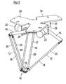
- Fig. 1 an inventive delta robot is shown.
- the robot comprises a tool holder 10 which is connected to a robot base 14 via three control arms 12.
- Each control arm 12 includes an upper arm portion 16 and a lower arm portion 18 that includes a pair of thin-walled tubes 20.
- the tubes 20 may be made of stainless steel or carbon fiber and are each pivotally connected to the associated upper arm portion 16 and the tool holder 10.
- the upper arm portions 16 are mounted offset by 120 ° to each other pivotally mounted on the robot base 14.
- a main drive 22 is associated with each upper arm portion 16, which includes an electric motor including transmission and storage.
- the main drives 22 are designed so that they can be installed without an additional housing.
- the three main drives 22 are arranged along a circle and each spaced at 120 ° to each other.
- the axes of rotation of the main drives 22 are parallel to respective tangents of the circle at an angular displacement of 120 °.
- the robot base 14 has a base plate 24, on the underside of which three plate-shaped bearing seats 26 for the main drives 22 are attached, eg welded, ( Fig. 1 and 2 ).
- the main drives 22 may be bolted to the bearing seats 26.
- the robot can be mounted on a suitable support structure, also called cell construction, e.g. be screwed.
- Each upper arm portion 16 is directly connected to an output shaft 28 of the associated main drive 22, for example screwed.
- the corresponding screws are covered by a cover 30 ( Fig. 3 ).
- a seal (not shown) which is implemented in a cover disk 32.
- the bearing shells 42 serve to receive the rod ends 34 and are accordingly adapted to the shape of the rod ends 34.
- the tubes 20 of a control arm 12 are held together by means of a tension spring 48.
- the tension spring 48 is at each of its ends with a holder 50 in the form of a substantially U-shaped bracket connected, which is mounted by means of a dowel screw 60 pivotally mounted on one of the joint receptacles 36.
- the dowel screw 60 extends through a bearing sleeve 62, which is inserted into a bore 64 extending transversely through the joint receptacle 36 ( Fig. 5 and 6 ).
- tension spring 48 is particularly well suited for holding the tubes 20 together, it should be noted that, instead of the tension spring 48, another component with elastic properties, e.g. an elastomer, or a non-resilient connecting element for holding the tubes 20 can be used.
- another component with elastic properties e.g. an elastomer, or a non-resilient connecting element for holding the tubes 20 can be used.
- the pairs of tubes 20 forming the lower arm portions 18 are hinged not only to their respective upper arm portion 16 but also to the tool holder 10 by means of ball joints of the type described above in connection with FIG 4 to 6 has been described.
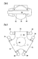
- the tool holder 10 has a hinge plate 66, which comprises three arranged around a central bore 68 around plate portions 70, which are each spaced by 120 ° to each other. Each plate portion 70 is associated with a control arm 12. Rod ends 34 are mounted on opposite sides of each plate portion 70 and are provided for receiving the hinge seats 36 which are connected to the tubes 20 of the corresponding control arm 12. With regard to the construction of these joint receptacles 36 is on 4 to 6 and the related description. Also in the area of the hinge plate 66, the tubes 20 of a control arm 12 are held together by a (not shown) tension spring, which by means of holders 50 of the already described Art is connected to the joint receptacles 36. According to the above statements, an inelastic connecting element can also be used here instead of a tension spring.
- an electric geared motor 74 is arranged to rotate a tool received by the tool holder 10, eg a gripper, about an axis perpendicular to the hinge plate 66.
- the gear motor 74 in other words forms a drive for the so-called fourth axis.
- the geared motor 74 is housed in a seated on the hinge plate 66 housing 76 ( FIGS. 7 and 8 ).
- the gear motor 74 and the housing 76 may be bolted to the hinge plate 66.
- the gear motor 74 On its underside, the gear motor 74 has a base portion 78 which engages at least approximately positively in the bore 68 of the hinge plate 66 in order to ensure a correct positioning of the geared motor 74 on the hinge plate 66 ( Figs. 10A and 10B ).
- an adapter for the male tool is mounted at an over the bottom 80 of the hinge plate 66 outstanding portion of an output shaft (not shown) of the geared motor 74.
- the adapter 82 has a in a plane perpendicular to the output shaft of the geared motor 74 level non-round, in particular polygonal profile, which is adapted to the cross section of a receptacle of the male tool for the adapter 82 to a rotation of the adapter 82 relative to the recorded tool to prevent.
- the male tool can be flanged directly to the gear motor 74 and in particular directly without the interposition of an additional gear. By directly flanging the tool to the geared motor 74 can be dispensed with storage of the fourth axis in the hinge plate 66.
Landscapes
- Engineering & Computer Science (AREA)
- Robotics (AREA)
- Mechanical Engineering (AREA)
- Manipulator (AREA)
Abstract
Description
- Die Erfindung betrifft einen Roboter mit Delta-Kinematik.
- Ein nach dem Delta-Prinzip arbeitender Roboter, welcher auch als Delta-Roboter oder als Parallelroboter bezeichnet wird, ist grundsätzlich bekannt und wird, beispielsweise im Bereich der Lebensmittelindustrie, zur schnellen und präzisen Positionierung von leichten Gegenständen, wie z.B. Lebensmittelportionen, mittels Vakuumsaugern oder Greifern eingesetzt. Ein besonderer Vorteil der Delta-Kinematik liegt in der hohen Dynamik und in der besonderen Genauigkeit, mit welcher Positionen angefahren werden können.
- Ein Delta-Roboter umfasst typischerweise eine meist ortsfest angeordnete Roboterbasis und eine relativ zu der Roboterbasis bewegbare Werkzeugaufnahme, an welcher ein an den jeweiligen Anwendungsbereich angepasstes Werkzeug, z.B. ein Greifer, angebracht ist. Die Werkzeugaufnahme ist mittels mindestens dreier motorisch angetriebener, bewegbarer Steuerarme mit der Roboterbasis verbunden. Jeder Steuerarm umfasst einen an der Roboterbasis befestigten oberen Armabschnitt und einen an den oberen Armabschnitt angelenkten und zu der Werkzeugaufnahme führenden unteren Armabschnitt.
- Zum Verdrehen eines an der Werkzeugaufnahme angebrachten Werkzeugs um seine Achse, die auch als vierte Achse bezeichnet wird, ist typischerweise ein Drehantrieb im Bereich der Roboterbasis ortsfest angeordnet, dessen Drehmoment zu der bewegbaren Werkzeugaufnahme übertragen werden muss.
- Bekannte Delta-Roboter weisen hierfür eine Teleskopachse auf. Die Drehmomentübertragung erfolgt dabei mittels einer Vielkeilwelle oder durch eine seitlich versetzte Anordnung von Profilelementen. Beide Lösungen zeichnen sich dadurch aus, dass die Drehmomenteinleitung in die Teleskopachse über ein mit der Roboterbasis fest verbundenes, gelenkig gelagertes Ende eines ersten Teils eines Schiebesitzes stattfindet, während die Drehmomentausleitung über ein relativ zu dem ersten Teil verschiebbares zweites Teil des Schiebesitzes erfolgt, welches an der Werkzeugaufnahme angebracht ist.
- Diese Einrichtungen zur Übertragung von Drehmoment sind verschleißanfällig und lediglich zur Übertragung kleinerer Drehmomente geeignet. Ferner führt eine Reduzierung des notwendigerweise vorhandenen Spiels in der Drehmomentübertragungseinrichtung zwangsläufig zu Schwergängigkeiten des Gesamtsystems. Ein weiterer Nachteil ist die Hubbegrenzung.
- Der Erfindung liegt die Aufgabe zugrunde, einen Delta-Roboter zu schaffen, bei welchem die vierte Achse mit einem geringeren mechanischen Aufwand antreibbar ist.
- Zur Lösung der Aufgabe ist ein Roboter mit den Merkmalen des Anspruchs 1 vorgesehen.
- Der erfindungsgemäße Roboter umfasst eine Werkzeugaufnahme, die eine über Steuerarme mit einer Roboterbasis verbundene Gelenkplatte und einen Antrieb zum Verdrehen eines von der Werkzeugaufnahme aufgenommenen Werkzeugs aufweist, welcher an der Gelenkplatte befestigt ist.
- Der Erfindung liegt der allgemeine Gedanke zugrunde, den Antrieb zum Verdrehen des Werkzeugs, d.h. den Antrieb für die vierte Achse, nicht an der Roboterbasis, sondern stattdessen an der Gelenkplatte anzubringen. Der Antrieb zum Verdrehen des Werkzeugs ist mit anderen Worten also in die Werkzeugaufnahme integriert.
- Erfindungsgemäß braucht also kein Drehmoment von der Roboterbasis an die Werkzeugaufnahme übertragen zu werden. Der erfindungsgemäße Roboter kommt folglich ohne eine Einrichtung zur Übertragung von Drehmoment zwischen der Roboterbasis und der Werkzeugaufnahme aus und weist dadurch einen einfacheren mechanischen Aufbau auf. Insbesondere werden die Probleme überwunden, die sich beispielsweise aus der Verschleißanfälligkeit bekannter Drehmomentübertragungseinrichtungen bzw. aus der Schwergängigkeit des Gesamtsystems aufgrund solcher Drehmomentübertragungseinrichtungen ergeben.
- Vorteilhafte Ausbildungen der Erfindung sind den Unteransprüchen, der Beschreibung und der Zeichnung zu entnehmen.
- Gemäß einer Ausführungsform ist der Antrieb durch einen Motor, insbesondere einen Elektromotor, gebildet. Handelt es sich bei dem Motor überdies um einen Getriebemotor, wird eine besondere Kompaktheit des Antriebs erreicht, da ein Getriebe in diesem Fall bereits in den Motor integriert ist und folglich kein zusätzliches Getriebe zwischen Motor und Werkzeug vorgesehen werden muss. Vielmehr kann das Werkzeug direkt an eine Ausgangswelle des Motors angekoppelt werden. Vorteilhafterweise ist der Antrieb in einem Gehäuse untergebracht. Der Roboter lässt sich hierdurch leicht reinigen und eignet sich somit besonders gut für hygienesensitive Anwendungen, wie beispielsweise der Handhabung von Lebensmittelprodukten.
- Gemäß einer weiteren Ausführungsform ist der Antrieb an einer dem Werkzeug abgewandten Seite der Gelenkplatte befestigt. Der Antrieb sitzt mit anderen Worten auf der Oberseite der Gelenkplatte, während das Werkzeug an der Unterseite der Gelenkplatte von der Werkzeugaufnahme aufgenommen wird.
- Um die Übertragung von Drehmoment von dem auf der Oberseite der Gelenkplatte sitzenden Antrieb an das an der Unterseite der Gelenkplatte aufgenommene Werkzeug zu ermöglichen, ist bevorzugt eine Bohrung in der Gelenkplatte vorgesehen. Die Bohrung ist vorteilhafterweise zentral ausgerichtet, d.h. der Mittelpunkt der Bohrung fällt mit dem Mittelpunkt der Gelenkplatte zusammen.
- Durch die Bohrung hindurch kann sich eine Ausgangswelle des Antriebs erstrecken.
- Besonders vorteilhaft ist es ferner, wenn ein Abschnitt des Antriebs, insbesondere formschlüssig, in die Bohrung eingreift, da hierdurch auf besonders einfache Weise eine korrekte Ausrichtung des Antriebs relativ zu der Gelenkplatte sichergestellt ist.
- Damit das Werkzeug direkt an den Antrieb angekoppelt werden kann, ragt eine Ausgangswelle des Antriebs vorzugsweise über die Gelenkplatte hinaus.
- Eine Ankopplung des aufzunehmenden Werkzeugs an den Antrieb gestaltet sich noch einfacher, wenn ein Adapter für das aufzunehmende Werkzeug an einer Ausgangswelle des Antriebs angebracht ist. Dabei kann der Adapter derart ausgebildet sein, dass das Werkzeug lediglich auf den Adapter aufgesteckt zu werden braucht und mittels einer geeigneten Verriegelung an diesem arretiert wird. Eine derartige Verriegelung kann beispielsweise einen Rastmechanismus und/oder eine Sicherungsschraube bzw. einen Sicherungsstift umfassen. Damit sich der Adapter bei einer Übertragung von Drehmoment von dem Antrieb an das Werkzeug nicht relativ zu dem Werkzeug verdreht, kann der Adapter ein unrundes Profil, beispielsweise ein Mehrkantprofil aufweisen, welches vorteilhafterweise an den Querschnitt einer Aufnahme des Werkzeugs zur Aufnahme des Adapters angepasst ist.
- Nachfolgend wird die Erfindung rein beispielhaft anhand einer vorteilhaften Ausführungsform unter Bezugnahme auf die beigefügte Zeichnung beschrieben. Es zeigen:
- Fig. 1
- eine perspektivische Ansicht eines erfindungsgemäßen Roboters;
- Fig. 2
- eine perspektivische Ansicht einer Roboterbasis des Roboters von
Fig. 1 ; - Fig. 3
- eine perspektivische Teilansicht, welche die Befesti- gung eines Antriebs für einen Steuerarm des Roboters von
Fig. 1 an der Roboterbasis zeigt; - Fig. 4
- eine perspektivische Teilansicht, welche die Lagerung eines unteren Armabschnitts an einem oberen Armab- schnitt eines Steuerarms des Roboters von
Fig. 1 zeigt; - Fig. 5
- eine perspektivische Schnittansicht einer Gelenkauf- nahme;
- Fig. 6
- eine Querschnittsansicht einer Gelenkaufnahme mit Lagerhülse und Passschraube;
- Fig. 7
- eine perspektivische Ansicht einer Werkzeugaufnahme des Roboters von
Fig. 1 von oben; - Fig. 8
- eine perspektivische Ansicht der Werkzeugaufnahme von
Fig. 7 von unten; - Fig. 9
- eine Draufsicht auf eine Gelenkplatte mit kugelförmi- gen Gelenkköpfen; und
- Fig. 10A und B
- perspektivische Ansichten der Werkzeugaufnahme mit aufgeschnittener Gelenkplatte und nicht eingehaustem Motor.
- In
Fig. 1 ist ein erfindungsgemäßer Delta-Roboter dargestellt. Der Roboter umfasst eine Werkzeugaufnahme 10, die über drei Steuerarme 12 mit einer Roboterbasis 14 verbunden ist. - Jeder Steuerarm 12 umfasst einen oberen Armabschnitt 16 und einen unteren Armabschnitt 18, welcher ein Paar von dünnwandigen Rohren 20 umfasst. Die Rohre 20 können aus Edelstahl oder Kohlenstofffaser bestehen und sind jeweils mit dem zugeordneten oberen Armabschnitt 16 und der Werkzeugaufnahme 10 gelenkig verbunden.
- Die oberen Armabschnitte 16 sind um 120° zueinander versetzt verschwenkbar an der Roboterbasis 14 gelagert. Zur Verschwenkung der oberen Armabschnitte 16 ist jedem oberen Armabschnitt 16 ein Hauptantrieb 22 zugeordnet, welcher einen Elektromotor einschließlich Getriebe und Lagerung umfasst. Dabei sind die Hauptantriebe 22 so ausgeführt, dass sie ohne eine zusätzliche Einhausung verbaut werden können. Die drei Hauptantriebe 22 sind entlang eines Kreises angeordnet und jeweils um 120° zueinander beabstandet. Dabei liegen die Drehachsen der Hauptantriebe 22 parallel zu jeweiligen Tangenten des Kreises bei einem Winkelversatz von 120°.
- Die Roboterbasis 14 weist eine Grundplatte 24 auf, an deren Unterseite drei plattenförmige Lagersitze 26 für die Hauptantriebe 22 angebracht, z.B. angeschweißt, sind (
Fig. 1 und2 ). Die Hauptantriebe 22 können an die Lagersitze 26 angeschraubt sein. - Mit Hilfe der Roboterbasis 14 und insbesondere mittels der Grundplatte 24 kann der Roboter an einer geeigneten Trägerstruktur, auch Zellenkonstruktion genannt, montiert, z.B. verschraubt, werden.
- Jeder obere Armabschnitt 16 ist direkt mit einer Ausgangswelle 28 des zugeordneten Hauptantriebs 22 verbunden, z.B. verschraubt. Die entsprechenden Schrauben sind durch eine Abdeckung 30 verdeckt (
Fig. 3 ). Zwischen jedem oberen Armabschnitt 16 und seinem zugeordneten Lagersitz 26 ist eine Dichtung (nicht gezeigt) vorgesehen, welche in einer Deckscheibe 32 implementiert ist. - Die gelenkige Verbindung der Rohre 20 eines unteren Armabschnitts 18 mit seinem oberen Armabschnitt 16 erfolgt mit Hilfe zweier Kugelgelenke, die auf gegenüberliegenden Seiten des oberen Armabschnitts 16 angeordnet sind (
Fig. 4 ). - Jedes Kugelgelenk umfasst einen in ein Trägerteil 33 des oberen Armabschnitts 16 eingeschraubten Gelenkkopf 34 und eine dem Gelenkkopf 34 zugeordnete Gelenkaufnahme 36, die an einem Rohr 20 des unteren Armabschnitts 16 angebracht ist. Beispielsweise können die Gelenkaufnahmen 36 in die Rohre 20 eingeklebt und/oder formschlüssig in diese eingesetzt sein.
- Jede Gelenkaufnahme 36 weist in einem dem Rohr 20 abgewandten vorderen Abschnitt 38 eine im Wesentlichen halbsphärisch ausgebildete Lagerschalenaufnahme 40 auf, in die eine Lagerschale 42 eingesetzt ist. Die Lagerschale 42 ist durch eine Übermaßpassung reibschlüssig in der Lagerschalenaufnahme 40 fixiert und/oder lösbar mit dieser verklebt. In dem vorderen Abschnitt 38 der Gelenkaufnahme 36 ist ferner eine Bohrung 44 vorgesehen, die es ermöglicht, die Lagerschale 42 aus der Lagerschalenaufnahme 40 herauszudrücken. Zur Gewährleistung einer exakten Positionierung der Lagerschale 42 in der Lagerschalenaufnahme 40 besitzt die Lagerschale 42 einen Sockel 46, der formschlüssig in die Bohrung 44 eingreift.
- Die Lagerschalen 42 dienen zur Aufnahme der Gelenkköpfe 34 und sind dementsprechend an die Form der Gelenkköpfe 34 angepasst. Um ein Abspringen der Gelenkaufnahmen 36 von ihrem jeweiligen Gelenkkopf 34 zu verhindern, werden die Rohre 20 eines Steuerarms 12 mittels einer Zugfeder 48 zusammengehalten. Die Zugfeder 48 ist an jedem ihrer Enden mit einem Halter 50 in Gestalt eines im Wesentlichen U-förmigen Bügels verbunden, welcher mittels einer Passschraube 60 verschwenkbar an einer der Gelenkaufnahmen 36 gelagert ist. Die Passschraube 60 erstreckt sich durch eine Lagerhülse 62, welche in eine sich quer durch die Gelenkaufnahme 36 hindurch erstreckende Bohrung 64 eingesetzt ist (
Fig. 5 und6 ). - Obwohl sich eine Zugfeder 48 besonders gut zum Zusammenhalten der Rohre 20 eignet, sei darauf hingewiesen, dass anstelle der Zugfeder 48 grundsätzlich auch ein anderes Bauteil mit elastischen Eigenschaften, z.B. ein Elastomer, oder ein nicht federndes Verbindungselement zum Zusammenhalten der Rohre 20 verwendet werden kann.
- Wie
Fig. 1 und insbesondere auchFig. 7 und 8 zu entnehmen ist, sind die die unteren Armabschnitte 18 bildenden Paare von Rohren 20 nicht nur mit ihrem jeweiligen oberen Armabschnitt 16, sondern auch mit der Werkzeugaufnahme 10 gelenkig verbunden, und zwar mit Hilfe von Kugelgelenken der Art, wie sie voranstehend in Verbindung mitFig. 4 bis 6 beschrieben wurde. - Die Werkzeugaufnahme 10 weist eine Gelenkplatte 66 auf, welche drei um eine zentrale Bohrung 68 herum angeordnete Plattenabschnitte 70 umfasst, die jeweils um 120° zueinander beabstandet sind. Jeder Plattenabschnitt 70 ist einem Steuerarm 12 zugeordnet. Gelenkköpfe 34 sind auf gegenüberliegenden Seiten jedes Plattenabschnitts 70 angebracht und zur Aufnahme der Gelenkaufnahmen 36 vorgesehen, die mit den Rohren 20 des entsprechenden Steuerarms 12 verbunden sind. Bezüglich des Aufbaus dieser Gelenkaufnahmen 36 wird auf
Fig. 4 bis 6 und die dazugehörige Beschreibung verwiesen. Auch im Bereich der Gelenkplatte 66 werden die Rohre 20 eines Steuerarms 12 durch eine (nicht dargestellte) Zugfeder zusammengehalten, die mit Hilfe von Haltern 50 der bereits beschriebenen Art mit den Gelenkaufnahmen 36 verbunden ist. Entsprechend den voranstehenden Ausführungen kann auch hier anstelle einer Zugfeder ein unelastisches Verbindungselement verwendet werden. - Auf einer zur Roboterbasis 14 weisenden Oberseite 72 der Gelenkplatte 66 ist ein elektrischer Getriebemotor 74 angeordnet, um ein von der Werkzeugaufnahme 10 aufgenommenes Werkzeug, z.B. einen Greifer, um eine zur Gelenkplatte 66 senkrechte Achse zu verdrehen. Der Getriebemotor 74 bildet mit anderen Worten einen Antrieb für die so genannte vierte Achse. Der Getriebemotor 74 ist in einem auf der Gelenkplatte 66 aufsitzenden Gehäuse 76 untergebracht (
Fig. 7 und 8 ). Der Getriebemotor 74 und das Gehäuse 76 können mit der Gelenkplatte 66 verschraubt sein. - An seiner Unterseite weist der Getriebemotor 74 einen Sockelabschnitt 78 auf, welcher zumindest annähernd formschlüssig in die Bohrung 68 der Gelenkplatte 66 eingreift, um eine korrekte Positionierung des Getriebemotors 74 auf der Gelenkplatte 66 zu gewährleisten (
Fig. 10A und 10B ). - An einem über die Unterseite 80 der Gelenkplatte 66 hervorragenden Abschnitt einer (nicht dargestellten) Ausgangswelle des Getriebemotors 74 ist ein Adapter für das aufzunehmende Werkzeug angebracht. Der Adapter 82 weist ein in einer zur Ausgangswelle des Getriebemotors 74 senkrechten Ebene unrundes, insbesondere mehrkantiges, Profil auf, welches an den Querschnitt einer Aufnahme des aufzunehmenden Werkzeugs für den Adapter 82 angepasst ist, um eine Verdrehung des Adapters 82 relativ zu dem aufgenommenen Werkzeug zu verhindern. Über den Adapter 82 lässt sich das aufzunehmende Werkzeug direkt und insbesondere ohne die Zwischenschaltung eins zusätzlichen Getriebes an den Getriebemotor 74 anflanschen. Durch das direkte Anflanschen des Werkzeugs an den Getriebemotor 74 kann auf eine Lagerung der vierten Achse in der Gelenkplatte 66 verzichtet werden.
-
- 10
- Werkzeugaufnahme
- 12
- Steuerarm
- 14
- Roboterbasis
- 16
- oberer Armabschnitt
- 18
- unterer Armabschnitt
- 20
- Rohr
- 22
- Hauptantrieb
- 24
- Grundplatte
- 26
- Lagersitz
- 28
- Hauptantriebsausgang
- 30
- Abdeckung
- 32
- Deckscheibe
- 33
- Trägerteil
- 34
- Gelenkkopf
- 36
- Gelenkaufnahme
- 38
- vorderer Abschnitt
- 40
- Lagerschalenaufnahme
- 42
- Lagerschale
- 44
- Bohrung
- 46
- Sockel
- 48
- Zugfeder
- 50
- Halter
- 60
- Passschraube
- 62
- Lagerhülse
- 64
- Bohrung
- 66
- Gelenkplatte
- 68
- Bohrung
- 70
- Plattenabschnitt
- 72
- Oberseite
- 74
- Getriebemotor
- 76
- Gehäuse
- 78
- Sockelabschnitt
- 80
- Unterseite
- 82
- Adapter
Claims (9)
- Roboter mit Delta-Kinematik, umfassend eine Werkzeugaufnahme (10), die eine über Steuerarme (12) mit einer Roboterbasis (14) verbundene Gelenkplatte (66) und einen Antrieb (74) zum Verdrehen eines von der Werkzeugaufnahme (10) aufgenommenen Werkzeugs aufweist, welcher an der Gelenkplatte (66) befestigt ist.
- Roboter nach Anspruch 1,
dadurch gekennzeichnet,dass
der Antrieb einen Motor, insbesondere einen Getriebemotor (74), umfasst. - Roboter nach Anspruch 1 oder 2,
dadurch gekennzeichnet, dass
der Antrieb (74) in einem Gehäuse (76) untergebracht ist. - Roboter nach einem der vorstehenden Ansprüche,
dadurch gekennzeichnet,dass
der Antrieb (74) an einer dem Werkzeug abgewandten Seite (72) der Gelenkplatte (66) befestigt ist. - Roboter nach einem der vorstehenden Ansprüche,
dadurch gekennzeichnet, dass
eine, insbesondere zentrale, Bohrung (68) in der Gelenkplatte (66) vorgesehen ist. - Roboter nach Anspruch 5,
dadurch gekennzeichnet, dass
sich eine Ausgangswelle des Antriebs (74) durch die Bohrung (68) hindurch erstreckt. - Roboter nach Anspruch 5 oder 6,
dadurch gekennzeichnet, dass
ein Abschnitt (78) des Antriebs (74), insbesondere formschlüssig, in die Bohrung (68) eingreift. - Roboter nach einem der vorstehenden Ansprüche,
dadurch gekennzeichnet, dass
ein freier Endabschnitt einer Ausgangswelle des Antriebs (74) über die Gelenkplatte (66) hinausragt. - Roboter nach einem der vorstehenden Ansprüche,
dadurch gekennzeichnet, dass
ein Adapter (82) für das aufzunehmende Werkzeug an einer Ausgangswelle des Antriebs (74) angebracht ist.
Applications Claiming Priority (1)
| Application Number | Priority Date | Filing Date | Title |
|---|---|---|---|
| DE102009017907A DE102009017907A1 (de) | 2009-04-17 | 2009-04-17 | Roboter mit Delta-Kinematik |
Publications (2)
| Publication Number | Publication Date |
|---|---|
| EP2241416A1 true EP2241416A1 (de) | 2010-10-20 |
| EP2241416B1 EP2241416B1 (de) | 2012-10-10 |
Family
ID=42174300
Family Applications (1)
| Application Number | Title | Priority Date | Filing Date |
|---|---|---|---|
| EP10002710A Not-in-force EP2241416B1 (de) | 2009-04-17 | 2010-03-15 | Roboter mit Delta-Kinematik |
Country Status (4)
| Country | Link |
|---|---|
| US (1) | US20100263471A1 (de) |
| EP (1) | EP2241416B1 (de) |
| JP (1) | JP2010247324A (de) |
| DE (1) | DE102009017907A1 (de) |
Cited By (11)
| Publication number | Priority date | Publication date | Assignee | Title |
|---|---|---|---|---|
| DE102010029784B3 (de) * | 2010-06-08 | 2011-07-28 | Beckhoff Automation GmbH, 33415 | Roboter |
| DE102011115980A1 (de) | 2011-10-13 | 2013-04-18 | Weber Maschinenbau Gmbh Breidenbach | Roboter mit einem ummantelten Roboterarm |
| CN103707281A (zh) * | 2012-09-29 | 2014-04-09 | 南昌大学 | 三维平动一维转动空间四自由度并联机构 |
| CN103802094A (zh) * | 2014-02-14 | 2014-05-21 | 青岛汇智机器人有限公司 | 一种并联机器人 |
| US9308652B2 (en) | 2010-06-08 | 2016-04-12 | Beckhoff Automation Gmbh | Robot module and robot with spacer rods arranged at gravity centers |
| CN106584442A (zh) * | 2015-10-19 | 2017-04-26 | 沈阳新松机器人自动化股份有限公司 | 五自由度的混联机构 |
| CN106625607A (zh) * | 2017-01-20 | 2017-05-10 | 常州大学 | 一种具有温度识别功能的少自由度并联抓取机器人 |
| CN107972017A (zh) * | 2017-12-29 | 2018-05-01 | 勃肯特(天津)机器人技术有限公司 | 六轴串并混联机器人 |
| WO2019206403A1 (en) | 2018-04-24 | 2019-10-31 | Abb Schweiz Ag | A parallel kinematic robot |
| EP3661817A1 (de) * | 2017-07-31 | 2020-06-10 | Aleksei Mozhar | Waschvorrichtung für fahrzeuge |
| WO2020181329A1 (en) * | 2019-03-12 | 2020-09-17 | Lamb Ian Conway | Active docking station for high-reliability landing and storage of uavs |
Families Citing this family (34)
| Publication number | Priority date | Publication date | Assignee | Title |
|---|---|---|---|---|
| DE102009006833A1 (de) * | 2009-01-30 | 2010-08-05 | Elau Gmbh | Deltaroboter für erhöhte Anforderungen an Dynamik, Hygiene und Kollisionsfolgenschutz |
| CN101708611B (zh) * | 2009-11-09 | 2011-07-27 | 天津大学 | 一种具有三维平动一维转动的并联机构 |
| JP2012161886A (ja) * | 2011-02-07 | 2012-08-30 | Jx Nippon Oil & Energy Corp | パイプ成形体 |
| EP2674265A4 (de) * | 2011-02-07 | 2014-08-06 | Jx Nippon Oil & Energy Corp | Geformter rohrkörper |
| JP2012161885A (ja) * | 2011-02-07 | 2012-08-30 | Jx Nippon Oil & Energy Corp | パイプ成形体 |
| JP5681564B2 (ja) * | 2011-05-23 | 2015-03-11 | 川崎重工業株式会社 | ロボット |
| RU2014122527A (ru) * | 2011-11-04 | 2015-12-10 | Те Джонс Хопкинс Юниверсити | Стационарный робот для ручных микроманипуляций |
| JP5516615B2 (ja) * | 2012-02-03 | 2014-06-11 | 株式会社安川電機 | パラレルリンクロボット |
| JP6043561B2 (ja) * | 2012-09-26 | 2016-12-14 | キヤノン電子株式会社 | パラレルリンクロボット |
| WO2014053670A1 (es) * | 2012-10-02 | 2014-04-10 | Avs Added Value Industrial Engineering Solutions, S.L. | Manipulador para una cámara de ultra-alto vacío |
| JP5977136B2 (ja) * | 2012-10-03 | 2016-08-24 | ヤマハ発動機株式会社 | アーム部材およびこのアーム部材を備える産業用ロボット |
| CN103101048B (zh) * | 2012-11-08 | 2015-04-22 | 上海理工大学 | 三自由度可调臂长并联机器人 |
| CN104029218A (zh) * | 2013-03-05 | 2014-09-10 | 深圳富泰宏精密工业有限公司 | 机械手臂 |
| CN103770106A (zh) * | 2014-02-12 | 2014-05-07 | 青岛汇智机器人有限公司 | 一种并联机器人底板 |
| CN103817689B (zh) * | 2014-02-12 | 2017-08-25 | 青岛汇智智能系统工程有限公司 | 一种并联机器人下底板 |
| CN103802093A (zh) * | 2014-02-14 | 2014-05-21 | 青岛汇智机器人有限公司 | 一种并联机器人固定板 |
| JP6563658B2 (ja) * | 2014-11-28 | 2019-08-21 | Ntn株式会社 | パラレルリンク機構を用いた作業装置 |
| WO2017015235A1 (en) * | 2015-07-17 | 2017-01-26 | The Johns Hopkins University | Delta mechanism with enhanced torsional stiffness |
| DE102015220357A1 (de) | 2015-10-20 | 2017-04-20 | Krones Aktiengesellschaft | Parallelkinematik-Roboter und Verfahren zum Betreiben eines solchen |
| CN105269558A (zh) * | 2015-10-22 | 2016-01-27 | 广州达意隆包装机械股份有限公司 | 一种并联机器人 |
| CN105773576A (zh) * | 2016-01-27 | 2016-07-20 | 大族激光科技产业集团股份有限公司 | 一种并联机器人 |
| MX2016016187A (es) * | 2016-12-07 | 2018-06-06 | Automatische Technik Mexico S A De C V | Robot industrial modular tipo delta reconfigurable, sistema y herramienta del mismo. |
| DE102017211642A1 (de) * | 2017-07-07 | 2019-01-10 | Kuka Deutschland Gmbh | Delta-Roboter |
| JP6698719B2 (ja) | 2018-02-14 | 2020-05-27 | ファナック株式会社 | パラレルリンクロボット |
| DE102018118257A1 (de) * | 2018-07-27 | 2020-01-30 | Gerhard Schubert Gmbh | Industrieroboter mit Parallelkinematik sowie Roboterstraße mit derartigen Industrierobotern |
| DE102018124754B4 (de) * | 2018-10-08 | 2022-03-24 | Koenig & Bauer Ag | Siebdruckvorrichtung mit einer Siebdruckschablone und mit mindestens zwei am Druckprozess beteiligten Rakelsystemen |
| US11059166B2 (en) | 2018-11-14 | 2021-07-13 | Battelle Energy Alliance, Llc | Linear delta systems with additional degrees of freedom and related methods |
| US10906172B2 (en) | 2018-11-14 | 2021-02-02 | Battelle Energy Alliance, Llc | Linear delta systems, hexapod systems, and related methods |
| US10821599B2 (en) * | 2018-11-14 | 2020-11-03 | Battelle Energy Alliance, Llc | Dual linear delta assemblies, linear delta systems, and related methods |
| GB2581848B (en) * | 2019-03-01 | 2021-09-22 | Millitec Food Systems Ltd | End effector carriage for delta robot |
| DE102019124358B4 (de) * | 2019-09-11 | 2021-11-11 | Deutsches Zentrum für Luft- und Raumfahrt e.V. | Manipulator |
| US11752645B2 (en) * | 2020-02-13 | 2023-09-12 | Boston Dynamics, Inc. | Non-planar linear actuator |
| CN113386168A (zh) * | 2021-05-13 | 2021-09-14 | 上海工程技术大学 | 一种用于检疫采样的仿生柔性机械手腕装置 |
| CN115781751B (zh) * | 2022-11-18 | 2026-02-10 | 富联裕展科技(深圳)有限公司 | 关节连接组件、摆动装置及移载系统 |
Citations (3)
| Publication number | Priority date | Publication date | Assignee | Title |
|---|---|---|---|---|
| US4976582A (en) | 1985-12-16 | 1990-12-11 | Sogeva S.A. | Device for the movement and positioning of an element in space |
| EP0997238A2 (de) * | 1998-10-27 | 2000-05-03 | Fanuc Ltd | Parallelstangenmechanismus |
| US6330837B1 (en) * | 1997-08-28 | 2001-12-18 | Microdexterity Systems, Inc. | Parallel mechanism |
Family Cites Families (7)
| Publication number | Priority date | Publication date | Assignee | Title |
|---|---|---|---|---|
| US5388935A (en) * | 1993-08-03 | 1995-02-14 | Giddings & Lewis, Inc. | Six axis machine tool |
| JP4632560B2 (ja) * | 2000-03-01 | 2011-02-16 | シーグ パック システムズ アクチェンゲゼルシャフト | 三次元空間内で製品を操作するロボット |
| US6896473B2 (en) * | 2001-09-17 | 2005-05-24 | Robert Bosch Gmbh | Device for transmitting torque |
| CA2546777C (en) * | 2003-12-02 | 2012-07-10 | Robert Bosch Gmbh | Rotary leadthrough of a robot arm |
| ES2258917B1 (es) * | 2005-02-17 | 2007-12-01 | Fundacion Fatronik | Robot paralelo con cuatro grados de libertad de alta velocidad. |
| JP4598864B2 (ja) * | 2009-01-29 | 2010-12-15 | ファナック株式会社 | パラレルロボット |
| JP4659098B2 (ja) * | 2009-02-13 | 2011-03-30 | ファナック株式会社 | 3自由度を有する姿勢変更機構を備えたパラレルリンクロボット |
-
2009
- 2009-04-17 DE DE102009017907A patent/DE102009017907A1/de not_active Withdrawn
-
2010
- 2010-03-15 EP EP10002710A patent/EP2241416B1/de not_active Not-in-force
- 2010-03-18 JP JP2010061880A patent/JP2010247324A/ja active Pending
- 2010-04-07 US US12/798,568 patent/US20100263471A1/en not_active Abandoned
Patent Citations (3)
| Publication number | Priority date | Publication date | Assignee | Title |
|---|---|---|---|---|
| US4976582A (en) | 1985-12-16 | 1990-12-11 | Sogeva S.A. | Device for the movement and positioning of an element in space |
| US6330837B1 (en) * | 1997-08-28 | 2001-12-18 | Microdexterity Systems, Inc. | Parallel mechanism |
| EP0997238A2 (de) * | 1998-10-27 | 2000-05-03 | Fanuc Ltd | Parallelstangenmechanismus |
Cited By (12)
| Publication number | Priority date | Publication date | Assignee | Title |
|---|---|---|---|---|
| DE102010029784B3 (de) * | 2010-06-08 | 2011-07-28 | Beckhoff Automation GmbH, 33415 | Roboter |
| US9308652B2 (en) | 2010-06-08 | 2016-04-12 | Beckhoff Automation Gmbh | Robot module and robot with spacer rods arranged at gravity centers |
| DE102011115980A1 (de) | 2011-10-13 | 2013-04-18 | Weber Maschinenbau Gmbh Breidenbach | Roboter mit einem ummantelten Roboterarm |
| CN103707281A (zh) * | 2012-09-29 | 2014-04-09 | 南昌大学 | 三维平动一维转动空间四自由度并联机构 |
| CN103802094A (zh) * | 2014-02-14 | 2014-05-21 | 青岛汇智机器人有限公司 | 一种并联机器人 |
| CN106584442A (zh) * | 2015-10-19 | 2017-04-26 | 沈阳新松机器人自动化股份有限公司 | 五自由度的混联机构 |
| CN106625607A (zh) * | 2017-01-20 | 2017-05-10 | 常州大学 | 一种具有温度识别功能的少自由度并联抓取机器人 |
| EP3661817A1 (de) * | 2017-07-31 | 2020-06-10 | Aleksei Mozhar | Waschvorrichtung für fahrzeuge |
| CN107972017A (zh) * | 2017-12-29 | 2018-05-01 | 勃肯特(天津)机器人技术有限公司 | 六轴串并混联机器人 |
| WO2019206403A1 (en) | 2018-04-24 | 2019-10-31 | Abb Schweiz Ag | A parallel kinematic robot |
| US11938624B2 (en) | 2018-04-24 | 2024-03-26 | Abb Schweiz Ag | Parallel kinematic robot |
| WO2020181329A1 (en) * | 2019-03-12 | 2020-09-17 | Lamb Ian Conway | Active docking station for high-reliability landing and storage of uavs |
Also Published As
| Publication number | Publication date |
|---|---|
| EP2241416B1 (de) | 2012-10-10 |
| US20100263471A1 (en) | 2010-10-21 |
| JP2010247324A (ja) | 2010-11-04 |
| DE102009017907A1 (de) | 2010-10-21 |
Similar Documents
| Publication | Publication Date | Title |
|---|---|---|
| EP2241416B1 (de) | Roboter mit Delta-Kinematik | |
| EP1998930B1 (de) | Positioniereinrichtung | |
| DE8310067U1 (de) | Robotergelenk | |
| DE102013011681A1 (de) | Nabelgliedanordnung eines Industrieroboters mit hohlem Glied | |
| DE10258105B4 (de) | Luftfahrzeug-Türanordnung | |
| DE3221955C2 (de) | Halte- und Bewegungsvorrichtung für einen Detektorkopf eines Emissions-Computer-Tomographen | |
| DE112004002263T5 (de) | Armmechanismus für Industrieroboter | |
| EP1415758A1 (de) | Bearbeitungseinheit für eine programmgesteuerte Fräs- und Bohrmaschine | |
| DE69017667T2 (de) | Elektrischer schweissroboter und ein verfahren zum schweissen mittels dieses roboters. | |
| EP3856465A1 (de) | Roboter-handführgerät | |
| EP4104977B1 (de) | Roboter mit komplementären befestigungselementen zur baugruppenverbindung | |
| DE102009003832A1 (de) | Lenkbare Verbundlenker-Hinterachse | |
| EP0627975B1 (de) | Vorrichtung zum manipulieren von gegenständen | |
| DE102007050905B4 (de) | Handhabungsvorrichtung mit Dreiringlager zwischen zwei äußeren Schwenkarmen und einer Plattform | |
| DE102006052402A1 (de) | Motorantreibbare Gelenk-Glied-Einheit für Roboterfinger oder Roboterarme und System hierfür | |
| DE102016205008B4 (de) | Fräskopf | |
| DE102010033429A1 (de) | Industrieroboter | |
| EP3523160B1 (de) | Getriebeanordnung für einen spindelantrieb, spindelantrieb und fahrzeugsitz | |
| DE102017118571B4 (de) | Winkelgetriebe | |
| EP3488972B1 (de) | Schwenkvorrichtung | |
| EP4487024B1 (de) | Montageanordnung, positioniervorrichtung mit einer solchen montageanordnung und vorrichtung zur herstellung einer solchen montageanordnung | |
| DE2654877C3 (de) | Gleichlaufdrehgelenk | |
| EP4244025B1 (de) | Roboteram und verfahren zum montieren eines roboterarms | |
| DE1775039B2 (de) | Antriebseinrichtung mit einem ritzel und einem zahnkranz | |
| DE202005006571U1 (de) | Elektromotorischer Möbelantrieb |
Legal Events
| Date | Code | Title | Description |
|---|---|---|---|
| PUAI | Public reference made under article 153(3) epc to a published international application that has entered the european phase |
Free format text: ORIGINAL CODE: 0009012 |
|
| AK | Designated contracting states |
Kind code of ref document: A1 Designated state(s): AT BE BG CH CY CZ DE DK EE ES FI FR GB GR HR HU IE IS IT LI LT LU LV MC MK MT NL NO PL PT RO SE SI SK SM TR |
|
| AX | Request for extension of the european patent |
Extension state: AL BA ME RS |
|
| 17P | Request for examination filed |
Effective date: 20110217 |
|
| 17Q | First examination report despatched |
Effective date: 20111108 |
|
| GRAP | Despatch of communication of intention to grant a patent |
Free format text: ORIGINAL CODE: EPIDOSNIGR1 |
|
| GRAS | Grant fee paid |
Free format text: ORIGINAL CODE: EPIDOSNIGR3 |
|
| GRAA | (expected) grant |
Free format text: ORIGINAL CODE: 0009210 |
|
| AK | Designated contracting states |
Kind code of ref document: B1 Designated state(s): AT BE BG CH CY CZ DE DK EE ES FI FR GB GR HR HU IE IS IT LI LT LU LV MC MK MT NL NO PL PT RO SE SI SK SM TR |
|
| REG | Reference to a national code |
Ref country code: GB Ref legal event code: FG4D Free format text: NOT ENGLISH |
|
| REG | Reference to a national code |
Ref country code: AT Ref legal event code: REF Ref document number: 578727 Country of ref document: AT Kind code of ref document: T Effective date: 20121015 Ref country code: CH Ref legal event code: EP |
|
| REG | Reference to a national code |
Ref country code: IE Ref legal event code: FG4D Free format text: LANGUAGE OF EP DOCUMENT: GERMAN |
|
| REG | Reference to a national code |
Ref country code: DE Ref legal event code: R096 Ref document number: 502010001399 Country of ref document: DE Effective date: 20121206 |
|
| PG25 | Lapsed in a contracting state [announced via postgrant information from national office to epo] |
Ref country code: SI Free format text: LAPSE BECAUSE OF FAILURE TO SUBMIT A TRANSLATION OF THE DESCRIPTION OR TO PAY THE FEE WITHIN THE PRESCRIBED TIME-LIMIT Effective date: 20121010 |
|
| REG | Reference to a national code |
Ref country code: NL Ref legal event code: VDEP Effective date: 20121010 |
|
| REG | Reference to a national code |
Ref country code: LT Ref legal event code: MG4D |
|
| PG25 | Lapsed in a contracting state [announced via postgrant information from national office to epo] |
Ref country code: IS Free format text: LAPSE BECAUSE OF FAILURE TO SUBMIT A TRANSLATION OF THE DESCRIPTION OR TO PAY THE FEE WITHIN THE PRESCRIBED TIME-LIMIT Effective date: 20130210 Ref country code: HR Free format text: LAPSE BECAUSE OF FAILURE TO SUBMIT A TRANSLATION OF THE DESCRIPTION OR TO PAY THE FEE WITHIN THE PRESCRIBED TIME-LIMIT Effective date: 20121010 Ref country code: FI Free format text: LAPSE BECAUSE OF FAILURE TO SUBMIT A TRANSLATION OF THE DESCRIPTION OR TO PAY THE FEE WITHIN THE PRESCRIBED TIME-LIMIT Effective date: 20121010 Ref country code: ES Free format text: LAPSE BECAUSE OF FAILURE TO SUBMIT A TRANSLATION OF THE DESCRIPTION OR TO PAY THE FEE WITHIN THE PRESCRIBED TIME-LIMIT Effective date: 20130121 Ref country code: NO Free format text: LAPSE BECAUSE OF FAILURE TO SUBMIT A TRANSLATION OF THE DESCRIPTION OR TO PAY THE FEE WITHIN THE PRESCRIBED TIME-LIMIT Effective date: 20130110 Ref country code: NL Free format text: LAPSE BECAUSE OF FAILURE TO SUBMIT A TRANSLATION OF THE DESCRIPTION OR TO PAY THE FEE WITHIN THE PRESCRIBED TIME-LIMIT Effective date: 20121010 Ref country code: LT Free format text: LAPSE BECAUSE OF FAILURE TO SUBMIT A TRANSLATION OF THE DESCRIPTION OR TO PAY THE FEE WITHIN THE PRESCRIBED TIME-LIMIT Effective date: 20121010 Ref country code: SE Free format text: LAPSE BECAUSE OF FAILURE TO SUBMIT A TRANSLATION OF THE DESCRIPTION OR TO PAY THE FEE WITHIN THE PRESCRIBED TIME-LIMIT Effective date: 20121010 |
|
| PG25 | Lapsed in a contracting state [announced via postgrant information from national office to epo] |
Ref country code: LV Free format text: LAPSE BECAUSE OF FAILURE TO SUBMIT A TRANSLATION OF THE DESCRIPTION OR TO PAY THE FEE WITHIN THE PRESCRIBED TIME-LIMIT Effective date: 20121010 Ref country code: PT Free format text: LAPSE BECAUSE OF FAILURE TO SUBMIT A TRANSLATION OF THE DESCRIPTION OR TO PAY THE FEE WITHIN THE PRESCRIBED TIME-LIMIT Effective date: 20130211 Ref country code: PL Free format text: LAPSE BECAUSE OF FAILURE TO SUBMIT A TRANSLATION OF THE DESCRIPTION OR TO PAY THE FEE WITHIN THE PRESCRIBED TIME-LIMIT Effective date: 20121010 |
|
| PG25 | Lapsed in a contracting state [announced via postgrant information from national office to epo] |
Ref country code: CZ Free format text: LAPSE BECAUSE OF FAILURE TO SUBMIT A TRANSLATION OF THE DESCRIPTION OR TO PAY THE FEE WITHIN THE PRESCRIBED TIME-LIMIT Effective date: 20121010 Ref country code: BG Free format text: LAPSE BECAUSE OF FAILURE TO SUBMIT A TRANSLATION OF THE DESCRIPTION OR TO PAY THE FEE WITHIN THE PRESCRIBED TIME-LIMIT Effective date: 20130110 Ref country code: SK Free format text: LAPSE BECAUSE OF FAILURE TO SUBMIT A TRANSLATION OF THE DESCRIPTION OR TO PAY THE FEE WITHIN THE PRESCRIBED TIME-LIMIT Effective date: 20121010 Ref country code: EE Free format text: LAPSE BECAUSE OF FAILURE TO SUBMIT A TRANSLATION OF THE DESCRIPTION OR TO PAY THE FEE WITHIN THE PRESCRIBED TIME-LIMIT Effective date: 20121010 Ref country code: DK Free format text: LAPSE BECAUSE OF FAILURE TO SUBMIT A TRANSLATION OF THE DESCRIPTION OR TO PAY THE FEE WITHIN THE PRESCRIBED TIME-LIMIT Effective date: 20121010 |
|
| PLBE | No opposition filed within time limit |
Free format text: ORIGINAL CODE: 0009261 |
|
| STAA | Information on the status of an ep patent application or granted ep patent |
Free format text: STATUS: NO OPPOSITION FILED WITHIN TIME LIMIT |
|
| PG25 | Lapsed in a contracting state [announced via postgrant information from national office to epo] |
Ref country code: RO Free format text: LAPSE BECAUSE OF FAILURE TO SUBMIT A TRANSLATION OF THE DESCRIPTION OR TO PAY THE FEE WITHIN THE PRESCRIBED TIME-LIMIT Effective date: 20121010 Ref country code: IT Free format text: LAPSE BECAUSE OF FAILURE TO SUBMIT A TRANSLATION OF THE DESCRIPTION OR TO PAY THE FEE WITHIN THE PRESCRIBED TIME-LIMIT Effective date: 20121010 |
|
| 26N | No opposition filed |
Effective date: 20130711 |
|
| BERE | Be: lapsed |
Owner name: WEBER MASCHINENBAU G.M.B.H. BREIDENBACH Effective date: 20130331 |
|
| PG25 | Lapsed in a contracting state [announced via postgrant information from national office to epo] |
Ref country code: MC Free format text: LAPSE BECAUSE OF NON-PAYMENT OF DUE FEES Effective date: 20130331 |
|
| REG | Reference to a national code |
Ref country code: DE Ref legal event code: R097 Ref document number: 502010001399 Country of ref document: DE Effective date: 20130711 |
|
| PG25 | Lapsed in a contracting state [announced via postgrant information from national office to epo] |
Ref country code: CY Free format text: LAPSE BECAUSE OF FAILURE TO SUBMIT A TRANSLATION OF THE DESCRIPTION OR TO PAY THE FEE WITHIN THE PRESCRIBED TIME-LIMIT Effective date: 20121010 |
|
| REG | Reference to a national code |
Ref country code: FR Ref legal event code: ST Effective date: 20131129 |
|
| REG | Reference to a national code |
Ref country code: IE Ref legal event code: MM4A |
|
| PG25 | Lapsed in a contracting state [announced via postgrant information from national office to epo] |
Ref country code: BE Free format text: LAPSE BECAUSE OF NON-PAYMENT OF DUE FEES Effective date: 20130331 Ref country code: FR Free format text: LAPSE BECAUSE OF NON-PAYMENT OF DUE FEES Effective date: 20130402 Ref country code: IE Free format text: LAPSE BECAUSE OF NON-PAYMENT OF DUE FEES Effective date: 20130315 |
|
| PG25 | Lapsed in a contracting state [announced via postgrant information from national office to epo] |
Ref country code: MT Free format text: LAPSE BECAUSE OF FAILURE TO SUBMIT A TRANSLATION OF THE DESCRIPTION OR TO PAY THE FEE WITHIN THE PRESCRIBED TIME-LIMIT Effective date: 20121010 |
|
| REG | Reference to a national code |
Ref country code: CH Ref legal event code: PL |
|
| GBPC | Gb: european patent ceased through non-payment of renewal fee |
Effective date: 20140315 |
|
| PG25 | Lapsed in a contracting state [announced via postgrant information from national office to epo] |
Ref country code: GB Free format text: LAPSE BECAUSE OF NON-PAYMENT OF DUE FEES Effective date: 20140315 Ref country code: CH Free format text: LAPSE BECAUSE OF NON-PAYMENT OF DUE FEES Effective date: 20140331 Ref country code: LI Free format text: LAPSE BECAUSE OF NON-PAYMENT OF DUE FEES Effective date: 20140331 |
|
| PG25 | Lapsed in a contracting state [announced via postgrant information from national office to epo] |
Ref country code: SM Free format text: LAPSE BECAUSE OF FAILURE TO SUBMIT A TRANSLATION OF THE DESCRIPTION OR TO PAY THE FEE WITHIN THE PRESCRIBED TIME-LIMIT Effective date: 20121010 |
|
| PG25 | Lapsed in a contracting state [announced via postgrant information from national office to epo] |
Ref country code: TR Free format text: LAPSE BECAUSE OF FAILURE TO SUBMIT A TRANSLATION OF THE DESCRIPTION OR TO PAY THE FEE WITHIN THE PRESCRIBED TIME-LIMIT Effective date: 20121010 |
|
| PG25 | Lapsed in a contracting state [announced via postgrant information from national office to epo] |
Ref country code: MK Free format text: LAPSE BECAUSE OF FAILURE TO SUBMIT A TRANSLATION OF THE DESCRIPTION OR TO PAY THE FEE WITHIN THE PRESCRIBED TIME-LIMIT Effective date: 20121010 Ref country code: HU Free format text: LAPSE BECAUSE OF FAILURE TO SUBMIT A TRANSLATION OF THE DESCRIPTION OR TO PAY THE FEE WITHIN THE PRESCRIBED TIME-LIMIT; INVALID AB INITIO Effective date: 20100315 Ref country code: LU Free format text: LAPSE BECAUSE OF NON-PAYMENT OF DUE FEES Effective date: 20130315 |
|
| PG25 | Lapsed in a contracting state [announced via postgrant information from national office to epo] |
Ref country code: GR Free format text: LAPSE BECAUSE OF NON-PAYMENT OF DUE FEES Effective date: 20121010 |
|
| REG | Reference to a national code |
Ref country code: AT Ref legal event code: MM01 Ref document number: 578727 Country of ref document: AT Kind code of ref document: T Effective date: 20150315 |
|
| PGFP | Annual fee paid to national office [announced via postgrant information from national office to epo] |
Ref country code: DE Payment date: 20160330 Year of fee payment: 7 |
|
| PG25 | Lapsed in a contracting state [announced via postgrant information from national office to epo] |
Ref country code: AT Free format text: LAPSE BECAUSE OF NON-PAYMENT OF DUE FEES Effective date: 20150315 |
|
| REG | Reference to a national code |
Ref country code: DE Ref legal event code: R119 Ref document number: 502010001399 Country of ref document: DE |
|
| PG25 | Lapsed in a contracting state [announced via postgrant information from national office to epo] |
Ref country code: DE Free format text: LAPSE BECAUSE OF NON-PAYMENT OF DUE FEES Effective date: 20171003 |