EP2241416A1 - Robot doté d'une cinématique delta - Google Patents
Robot doté d'une cinématique delta Download PDFInfo
- Publication number
- EP2241416A1 EP2241416A1 EP10002710A EP10002710A EP2241416A1 EP 2241416 A1 EP2241416 A1 EP 2241416A1 EP 10002710 A EP10002710 A EP 10002710A EP 10002710 A EP10002710 A EP 10002710A EP 2241416 A1 EP2241416 A1 EP 2241416A1
- Authority
- EP
- European Patent Office
- Prior art keywords
- drive
- tool
- robot
- hinge plate
- robot according
- Prior art date
- Legal status (The legal status is an assumption and is not a legal conclusion. Google has not performed a legal analysis and makes no representation as to the accuracy of the status listed.)
- Granted
Links
Images


Classifications
-
- B—PERFORMING OPERATIONS; TRANSPORTING
- B25—HAND TOOLS; PORTABLE POWER-DRIVEN TOOLS; MANIPULATORS
- B25J—MANIPULATORS; CHAMBERS PROVIDED WITH MANIPULATION DEVICES
- B25J17/00—Joints
- B25J17/02—Wrist joints
- B25J17/0258—Two-dimensional joints
- B25J17/0266—Two-dimensional joints comprising more than two actuating or connecting rods
-
- B—PERFORMING OPERATIONS; TRANSPORTING
- B25—HAND TOOLS; PORTABLE POWER-DRIVEN TOOLS; MANIPULATORS
- B25J—MANIPULATORS; CHAMBERS PROVIDED WITH MANIPULATION DEVICES
- B25J9/00—Programme-controlled manipulators
- B25J9/003—Programme-controlled manipulators having parallel kinematics
- B25J9/0045—Programme-controlled manipulators having parallel kinematics with kinematics chains having a rotary joint at the base
- B25J9/0051—Programme-controlled manipulators having parallel kinematics with kinematics chains having a rotary joint at the base with kinematics chains of the type rotary-universal-universal or rotary-spherical-spherical, e.g. Delta type manipulators
-
- Y—GENERAL TAGGING OF NEW TECHNOLOGICAL DEVELOPMENTS; GENERAL TAGGING OF CROSS-SECTIONAL TECHNOLOGIES SPANNING OVER SEVERAL SECTIONS OF THE IPC; TECHNICAL SUBJECTS COVERED BY FORMER USPC CROSS-REFERENCE ART COLLECTIONS [XRACs] AND DIGESTS
- Y10—TECHNICAL SUBJECTS COVERED BY FORMER USPC
- Y10T—TECHNICAL SUBJECTS COVERED BY FORMER US CLASSIFICATION
- Y10T74/00—Machine element or mechanism
- Y10T74/20—Control lever and linkage systems
- Y10T74/20207—Multiple controlling elements for single controlled element
- Y10T74/20305—Robotic arm
- Y10T74/20329—Joint between elements
- Y10T74/20335—Wrist
Definitions
- the invention relates to a robot with delta kinematics.
- a delta principle robot also referred to as a delta robot or a parallel robot, is basically known and, for example in the food industry, is used for the quick and precise positioning of light objects such as e.g. Food portions, used by means of vacuum cups or grippers.
- a particular advantage of delta kinematics lies in the high dynamics and the particular accuracy with which positions can be approached.
- a rotary drive For rotating a tool attached to the tool holder about its axis, which is also referred to as the fourth axis, typically a rotary drive is arranged in the area of the robot base in a stationary manner, whose torque must be transmitted to the movable tool holder.
- Known delta robots have a telescopic axis for this purpose.
- the torque transmission takes place by means of a splined shaft or by a laterally offset arrangement of profile elements.
- Both solutions are characterized in that the torque introduction takes place in the telescopic axis via a fixedly connected to the robot base, hinged end of a first part of a sliding seat, while the torque is carried out via a relative to the first part displaceable second part of the sliding seat, which the tool holder is attached.
- the robot according to the invention does not require any means for transmitting torque between the robot base and the tool holder and thus has a simpler mechanical construction.
- the problems that arise, for example, from the susceptibility to wear of known torque transmission devices or from the stiffness of the overall system due to such torque transmission devices are overcome.
- the drive is formed by a motor, in particular an electric motor.
- the motor is a geared motor, a particular compactness of the drive is achieved since a gearbox is already integrated in the motor in this case and consequently no additional gearbox must be provided between the motor and the tool. Rather, the tool can be coupled directly to an output shaft of the engine.
- the drive is housed in a housing. The robot is therefore easy to clean and is thus particularly well suited for hygiene-sensitive applications, such as the handling of food products.
- the drive is fastened to a side of the hinge plate facing away from the tool.
- the drive sits on top of the hinge plate while the tool is received by the tool holder at the bottom of the hinge plate.
- a hole in the hinge plate is preferably provided.
- the bore is advantageously centrally aligned, i. the center of the hole coincides with the center of the hinge plate.
- an output shaft of the drive can extend.
- an output shaft of the drive preferably protrudes beyond the hinge plate.
- a coupling of the male tool to the drive is even easier if an adapter for the male tool is attached to an output shaft of the drive.
- the adapter may be designed such that the tool only needs to be plugged onto the adapter and is locked by means of a suitable lock on this.
- a suitable lock may include, for example, a latching mechanism and / or a locking screw or a locking pin.
- the adapter does not rotate relative to the tool during a transmission of torque from the drive to the tool, the adapter may have a non-circular profile, such as a polygonal profile, which is advantageously adapted to the cross section of a receptacle of the tool for receiving the adapter.
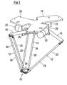
- Fig. 1 an inventive delta robot is shown.
- the robot comprises a tool holder 10 which is connected to a robot base 14 via three control arms 12.
- Each control arm 12 includes an upper arm portion 16 and a lower arm portion 18 that includes a pair of thin-walled tubes 20.
- the tubes 20 may be made of stainless steel or carbon fiber and are each pivotally connected to the associated upper arm portion 16 and the tool holder 10.
- the upper arm portions 16 are mounted offset by 120 ° to each other pivotally mounted on the robot base 14.
- a main drive 22 is associated with each upper arm portion 16, which includes an electric motor including transmission and storage.
- the main drives 22 are designed so that they can be installed without an additional housing.
- the three main drives 22 are arranged along a circle and each spaced at 120 ° to each other.
- the axes of rotation of the main drives 22 are parallel to respective tangents of the circle at an angular displacement of 120 °.
- the robot base 14 has a base plate 24, on the underside of which three plate-shaped bearing seats 26 for the main drives 22 are attached, eg welded, ( Fig. 1 and 2 ).
- the main drives 22 may be bolted to the bearing seats 26.
- the robot can be mounted on a suitable support structure, also called cell construction, e.g. be screwed.
- Each upper arm portion 16 is directly connected to an output shaft 28 of the associated main drive 22, for example screwed.
- the corresponding screws are covered by a cover 30 ( Fig. 3 ).
- a seal (not shown) which is implemented in a cover disk 32.
- the bearing shells 42 serve to receive the rod ends 34 and are accordingly adapted to the shape of the rod ends 34.
- the tubes 20 of a control arm 12 are held together by means of a tension spring 48.
- the tension spring 48 is at each of its ends with a holder 50 in the form of a substantially U-shaped bracket connected, which is mounted by means of a dowel screw 60 pivotally mounted on one of the joint receptacles 36.
- the dowel screw 60 extends through a bearing sleeve 62, which is inserted into a bore 64 extending transversely through the joint receptacle 36 ( Fig. 5 and 6 ).
- tension spring 48 is particularly well suited for holding the tubes 20 together, it should be noted that, instead of the tension spring 48, another component with elastic properties, e.g. an elastomer, or a non-resilient connecting element for holding the tubes 20 can be used.
- another component with elastic properties e.g. an elastomer, or a non-resilient connecting element for holding the tubes 20 can be used.
- the pairs of tubes 20 forming the lower arm portions 18 are hinged not only to their respective upper arm portion 16 but also to the tool holder 10 by means of ball joints of the type described above in connection with FIG 4 to 6 has been described.
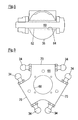
- the tool holder 10 has a hinge plate 66, which comprises three arranged around a central bore 68 around plate portions 70, which are each spaced by 120 ° to each other. Each plate portion 70 is associated with a control arm 12. Rod ends 34 are mounted on opposite sides of each plate portion 70 and are provided for receiving the hinge seats 36 which are connected to the tubes 20 of the corresponding control arm 12. With regard to the construction of these joint receptacles 36 is on 4 to 6 and the related description. Also in the area of the hinge plate 66, the tubes 20 of a control arm 12 are held together by a (not shown) tension spring, which by means of holders 50 of the already described Art is connected to the joint receptacles 36. According to the above statements, an inelastic connecting element can also be used here instead of a tension spring.
- an electric geared motor 74 is arranged to rotate a tool received by the tool holder 10, eg a gripper, about an axis perpendicular to the hinge plate 66.
- the gear motor 74 in other words forms a drive for the so-called fourth axis.
- the geared motor 74 is housed in a seated on the hinge plate 66 housing 76 ( FIGS. 7 and 8 ).
- the gear motor 74 and the housing 76 may be bolted to the hinge plate 66.
- the gear motor 74 On its underside, the gear motor 74 has a base portion 78 which engages at least approximately positively in the bore 68 of the hinge plate 66 in order to ensure a correct positioning of the geared motor 74 on the hinge plate 66 ( Figs. 10A and 10B ).
- an adapter for the male tool is mounted at an over the bottom 80 of the hinge plate 66 outstanding portion of an output shaft (not shown) of the geared motor 74.
- the adapter 82 has a in a plane perpendicular to the output shaft of the geared motor 74 level non-round, in particular polygonal profile, which is adapted to the cross section of a receptacle of the male tool for the adapter 82 to a rotation of the adapter 82 relative to the recorded tool to prevent.
- the male tool can be flanged directly to the gear motor 74 and in particular directly without the interposition of an additional gear. By directly flanging the tool to the geared motor 74 can be dispensed with storage of the fourth axis in the hinge plate 66.
Applications Claiming Priority (1)
| Application Number | Priority Date | Filing Date | Title |
|---|---|---|---|
| DE102009017907A DE102009017907A1 (de) | 2009-04-17 | 2009-04-17 | Roboter mit Delta-Kinematik |
Publications (2)
| Publication Number | Publication Date |
|---|---|
| EP2241416A1 true EP2241416A1 (fr) | 2010-10-20 |
| EP2241416B1 EP2241416B1 (fr) | 2012-10-10 |
Family
ID=42174300
Family Applications (1)
| Application Number | Title | Priority Date | Filing Date |
|---|---|---|---|
| EP10002710A Not-in-force EP2241416B1 (fr) | 2009-04-17 | 2010-03-15 | Robot doté d'une cinématique delta |
Country Status (4)
| Country | Link |
|---|---|
| US (1) | US20100263471A1 (fr) |
| EP (1) | EP2241416B1 (fr) |
| JP (1) | JP2010247324A (fr) |
| DE (1) | DE102009017907A1 (fr) |
Cited By (10)
| Publication number | Priority date | Publication date | Assignee | Title |
|---|---|---|---|---|
| DE102010029784B3 (de) * | 2010-06-08 | 2011-07-28 | Beckhoff Automation GmbH, 33415 | Roboter |
| DE102011115980A1 (de) | 2011-10-13 | 2013-04-18 | Weber Maschinenbau Gmbh Breidenbach | Roboter mit einem ummantelten Roboterarm |
| CN103707281A (zh) * | 2012-09-29 | 2014-04-09 | 南昌大学 | 三维平动一维转动空间四自由度并联机构 |
| CN103802094A (zh) * | 2014-02-14 | 2014-05-21 | 青岛汇智机器人有限公司 | 一种并联机器人 |
| US9308652B2 (en) | 2010-06-08 | 2016-04-12 | Beckhoff Automation Gmbh | Robot module and robot with spacer rods arranged at gravity centers |
| CN106584442A (zh) * | 2015-10-19 | 2017-04-26 | 沈阳新松机器人自动化股份有限公司 | 五自由度的混联机构 |
| CN106625607A (zh) * | 2017-01-20 | 2017-05-10 | 常州大学 | 一种具有温度识别功能的少自由度并联抓取机器人 |
| CN107972017A (zh) * | 2017-12-29 | 2018-05-01 | 勃肯特(天津)机器人技术有限公司 | 六轴串并混联机器人 |
| WO2019206403A1 (fr) | 2018-04-24 | 2019-10-31 | Abb Schweiz Ag | Robot cinématique parallèle |
| WO2020181329A1 (fr) * | 2019-03-12 | 2020-09-17 | Lamb Ian Conway | Station d'accueil active destinée à l'atterrissage et au stockage à haute fiabilité d'uav |
Families Citing this family (33)
| Publication number | Priority date | Publication date | Assignee | Title |
|---|---|---|---|---|
| DE102009006833A1 (de) * | 2009-01-30 | 2010-08-05 | Elau Gmbh | Deltaroboter für erhöhte Anforderungen an Dynamik, Hygiene und Kollisionsfolgenschutz |
| CN101708611B (zh) * | 2009-11-09 | 2011-07-27 | 天津大学 | 一种具有三维平动一维转动的并联机构 |
| JP2012161885A (ja) * | 2011-02-07 | 2012-08-30 | Jx Nippon Oil & Energy Corp | パイプ成形体 |
| US20140014219A1 (en) * | 2011-02-07 | 2014-01-16 | Jx Nippon Oil & Energy Corporation | Shaped pipe body |
| JP2012161886A (ja) * | 2011-02-07 | 2012-08-30 | Jx Nippon Oil & Energy Corp | パイプ成形体 |
| JP5681564B2 (ja) * | 2011-05-23 | 2015-03-11 | 川崎重工業株式会社 | ロボット |
| CA2854505C (fr) * | 2011-11-04 | 2020-03-24 | The Johns Hopkins University | Robot pour micromanipulation d'une main ferme |
| JP5516615B2 (ja) * | 2012-02-03 | 2014-06-11 | 株式会社安川電機 | パラレルリンクロボット |
| JP6043561B2 (ja) * | 2012-09-26 | 2016-12-14 | キヤノン電子株式会社 | パラレルリンクロボット |
| US20150321360A1 (en) * | 2012-10-02 | 2015-11-12 | Avs Added Value Industrial Engineering Solutions, S.L. | Manipulator for an ultra-high-vacuum chamber |
| JP5977136B2 (ja) | 2012-10-03 | 2016-08-24 | ヤマハ発動機株式会社 | アーム部材およびこのアーム部材を備える産業用ロボット |
| CN103101048B (zh) * | 2012-11-08 | 2015-04-22 | 上海理工大学 | 三自由度可调臂长并联机器人 |
| CN104029218A (zh) * | 2013-03-05 | 2014-09-10 | 深圳富泰宏精密工业有限公司 | 机械手臂 |
| CN103770106A (zh) * | 2014-02-12 | 2014-05-07 | 青岛汇智机器人有限公司 | 一种并联机器人底板 |
| CN103817689B (zh) * | 2014-02-12 | 2017-08-25 | 青岛汇智智能系统工程有限公司 | 一种并联机器人下底板 |
| CN103802093A (zh) * | 2014-02-14 | 2014-05-21 | 青岛汇智机器人有限公司 | 一种并联机器人固定板 |
| WO2017015235A1 (fr) * | 2015-07-17 | 2017-01-26 | The Johns Hopkins University | Mécanisme delta à rigidité supérieure en torsion |
| DE102015220357A1 (de) | 2015-10-20 | 2017-04-20 | Krones Aktiengesellschaft | Parallelkinematik-Roboter und Verfahren zum Betreiben eines solchen |
| CN105269558A (zh) * | 2015-10-22 | 2016-01-27 | 广州达意隆包装机械股份有限公司 | 一种并联机器人 |
| CN105773576A (zh) * | 2016-01-27 | 2016-07-20 | 大族激光科技产业集团股份有限公司 | 一种并联机器人 |
| MX2016016187A (es) * | 2016-12-07 | 2018-06-06 | Automatische Technik Mexico S A De C V | Robot industrial modular tipo delta reconfigurable, sistema y herramienta del mismo. |
| DE102017211642A1 (de) * | 2017-07-07 | 2019-01-10 | Kuka Deutschland Gmbh | Delta-Roboter |
| DE202017004032U1 (de) * | 2017-07-31 | 2018-11-05 | Aleksei Mozhar | Waschvorrichtung für Fahrzeuge |
| JP6698719B2 (ja) | 2018-02-14 | 2020-05-27 | ファナック株式会社 | パラレルリンクロボット |
| DE102018118257A1 (de) * | 2018-07-27 | 2020-01-30 | Gerhard Schubert Gmbh | Industrieroboter mit Parallelkinematik sowie Roboterstraße mit derartigen Industrierobotern |
| DE102018124754B4 (de) * | 2018-10-08 | 2022-03-24 | Koenig & Bauer Ag | Siebdruckvorrichtung mit einer Siebdruckschablone und mit mindestens zwei am Druckprozess beteiligten Rakelsystemen |
| US10906172B2 (en) | 2018-11-14 | 2021-02-02 | Battelle Energy Alliance, Llc | Linear delta systems, hexapod systems, and related methods |
| US11059166B2 (en) | 2018-11-14 | 2021-07-13 | Battelle Energy Alliance, Llc | Linear delta systems with additional degrees of freedom and related methods |
| US10821599B2 (en) * | 2018-11-14 | 2020-11-03 | Battelle Energy Alliance, Llc | Dual linear delta assemblies, linear delta systems, and related methods |
| GB2581848B (en) * | 2019-03-01 | 2021-09-22 | Millitec Food Systems Ltd | End effector carriage for delta robot |
| DE102019124358B4 (de) * | 2019-09-11 | 2021-11-11 | Deutsches Zentrum für Luft- und Raumfahrt e.V. | Manipulator |
| US11752645B2 (en) * | 2020-02-13 | 2023-09-12 | Boston Dynamics, Inc. | Non-planar linear actuator |
| CN113386168A (zh) * | 2021-05-13 | 2021-09-14 | 上海工程技术大学 | 一种用于检疫采样的仿生柔性机械手腕装置 |
Citations (3)
| Publication number | Priority date | Publication date | Assignee | Title |
|---|---|---|---|---|
| US4976582A (en) | 1985-12-16 | 1990-12-11 | Sogeva S.A. | Device for the movement and positioning of an element in space |
| EP0997238A2 (fr) * | 1998-10-27 | 2000-05-03 | Fanuc Ltd | Mécanisme d'actionnement à barres parallèles |
| US6330837B1 (en) * | 1997-08-28 | 2001-12-18 | Microdexterity Systems, Inc. | Parallel mechanism |
Family Cites Families (7)
| Publication number | Priority date | Publication date | Assignee | Title |
|---|---|---|---|---|
| US5388935A (en) * | 1993-08-03 | 1995-02-14 | Giddings & Lewis, Inc. | Six axis machine tool |
| JP4632560B2 (ja) * | 2000-03-01 | 2011-02-16 | シーグ パック システムズ アクチェンゲゼルシャフト | 三次元空間内で製品を操作するロボット |
| US6896473B2 (en) * | 2001-09-17 | 2005-05-24 | Robert Bosch Gmbh | Device for transmitting torque |
| DE112004002721B4 (de) * | 2003-12-02 | 2013-07-25 | Robert Bosch Gmbh | Drehdurchführung eines Roboterarms |
| ES2258917B1 (es) * | 2005-02-17 | 2007-12-01 | Fundacion Fatronik | Robot paralelo con cuatro grados de libertad de alta velocidad. |
| JP4598864B2 (ja) * | 2009-01-29 | 2010-12-15 | ファナック株式会社 | パラレルロボット |
| JP4659098B2 (ja) * | 2009-02-13 | 2011-03-30 | ファナック株式会社 | 3自由度を有する姿勢変更機構を備えたパラレルリンクロボット |
-
2009
- 2009-04-17 DE DE102009017907A patent/DE102009017907A1/de not_active Withdrawn
-
2010
- 2010-03-15 EP EP10002710A patent/EP2241416B1/fr not_active Not-in-force
- 2010-03-18 JP JP2010061880A patent/JP2010247324A/ja active Pending
- 2010-04-07 US US12/798,568 patent/US20100263471A1/en not_active Abandoned
Patent Citations (3)
| Publication number | Priority date | Publication date | Assignee | Title |
|---|---|---|---|---|
| US4976582A (en) | 1985-12-16 | 1990-12-11 | Sogeva S.A. | Device for the movement and positioning of an element in space |
| US6330837B1 (en) * | 1997-08-28 | 2001-12-18 | Microdexterity Systems, Inc. | Parallel mechanism |
| EP0997238A2 (fr) * | 1998-10-27 | 2000-05-03 | Fanuc Ltd | Mécanisme d'actionnement à barres parallèles |
Cited By (11)
| Publication number | Priority date | Publication date | Assignee | Title |
|---|---|---|---|---|
| DE102010029784B3 (de) * | 2010-06-08 | 2011-07-28 | Beckhoff Automation GmbH, 33415 | Roboter |
| US9308652B2 (en) | 2010-06-08 | 2016-04-12 | Beckhoff Automation Gmbh | Robot module and robot with spacer rods arranged at gravity centers |
| DE102011115980A1 (de) | 2011-10-13 | 2013-04-18 | Weber Maschinenbau Gmbh Breidenbach | Roboter mit einem ummantelten Roboterarm |
| CN103707281A (zh) * | 2012-09-29 | 2014-04-09 | 南昌大学 | 三维平动一维转动空间四自由度并联机构 |
| CN103802094A (zh) * | 2014-02-14 | 2014-05-21 | 青岛汇智机器人有限公司 | 一种并联机器人 |
| CN106584442A (zh) * | 2015-10-19 | 2017-04-26 | 沈阳新松机器人自动化股份有限公司 | 五自由度的混联机构 |
| CN106625607A (zh) * | 2017-01-20 | 2017-05-10 | 常州大学 | 一种具有温度识别功能的少自由度并联抓取机器人 |
| CN107972017A (zh) * | 2017-12-29 | 2018-05-01 | 勃肯特(天津)机器人技术有限公司 | 六轴串并混联机器人 |
| WO2019206403A1 (fr) | 2018-04-24 | 2019-10-31 | Abb Schweiz Ag | Robot cinématique parallèle |
| US11938624B2 (en) | 2018-04-24 | 2024-03-26 | Abb Schweiz Ag | Parallel kinematic robot |
| WO2020181329A1 (fr) * | 2019-03-12 | 2020-09-17 | Lamb Ian Conway | Station d'accueil active destinée à l'atterrissage et au stockage à haute fiabilité d'uav |
Also Published As
| Publication number | Publication date |
|---|---|
| EP2241416B1 (fr) | 2012-10-10 |
| DE102009017907A1 (de) | 2010-10-21 |
| US20100263471A1 (en) | 2010-10-21 |
| JP2010247324A (ja) | 2010-11-04 |
Similar Documents
| Publication | Publication Date | Title |
|---|---|---|
| EP2241416B1 (fr) | Robot doté d'une cinématique delta | |
| DE102013011681A1 (de) | Nabelgliedanordnung eines Industrieroboters mit hohlem Glied | |
| DE8310067U1 (de) | Robotergelenk | |
| WO2015144613A1 (fr) | Bras de robot et kit de montage | |
| DE10258105B4 (de) | Luftfahrzeug-Türanordnung | |
| DE102006052402A1 (de) | Motorantreibbare Gelenk-Glied-Einheit für Roboterfinger oder Roboterarme und System hierfür | |
| WO2007122181A1 (fr) | Dispositif de manipulation | |
| DE112004002263T5 (de) | Armmechanismus für Industrieroboter | |
| DE102009003832A1 (de) | Lenkbare Verbundlenker-Hinterachse | |
| EP3856464B1 (fr) | Robot pourvu d'éléments de fixation complémentaires permettant de raccorder les modules | |
| EP3523160B1 (fr) | Agencement de transmission pour mécanisme d'entraînement de broche, entraînement de broche et siège de véhicule | |
| EP3488972B1 (fr) | Dispositif de pivotement | |
| DE102010033429A1 (de) | Industrieroboter | |
| DE102016205008B4 (de) | Fräskopf | |
| DE202005006571U1 (de) | Elektromotorischer Möbelantrieb | |
| EP0342260B1 (fr) | Accouplement flexible pour opération intermittente par exemple entraînement de commutateurs | |
| DE102017118571B4 (de) | Winkelgetriebe | |
| DE4217128C2 (de) | Deckenversorgungseinheit | |
| DE102007050905B4 (de) | Handhabungsvorrichtung mit Dreiringlager zwischen zwei äußeren Schwenkarmen und einer Plattform | |
| EP2900417B1 (fr) | Module rotatif | |
| DE2654877C3 (de) | Gleichlaufdrehgelenk | |
| EP0627975B1 (fr) | Dispositif pour manipuler des objets | |
| DE102017121091A1 (de) | "Schweißzange, insbesondere zum Widerstandspunktschweißen" | |
| DE10107307A1 (de) | Flanschmitnehmer | |
| WO2018069234A1 (fr) | Ensemble adaptateur, procédé pour sa fabrication, système modulaire pour ensemble adaptateur, ensemble d'entraînement et procédé pour leur fabrication ainsi que siège de véhicule |
Legal Events
| Date | Code | Title | Description |
|---|---|---|---|
| PUAI | Public reference made under article 153(3) epc to a published international application that has entered the european phase |
Free format text: ORIGINAL CODE: 0009012 |
|
| AK | Designated contracting states |
Kind code of ref document: A1 Designated state(s): AT BE BG CH CY CZ DE DK EE ES FI FR GB GR HR HU IE IS IT LI LT LU LV MC MK MT NL NO PL PT RO SE SI SK SM TR |
|
| AX | Request for extension of the european patent |
Extension state: AL BA ME RS |
|
| 17P | Request for examination filed |
Effective date: 20110217 |
|
| 17Q | First examination report despatched |
Effective date: 20111108 |
|
| GRAP | Despatch of communication of intention to grant a patent |
Free format text: ORIGINAL CODE: EPIDOSNIGR1 |
|
| GRAS | Grant fee paid |
Free format text: ORIGINAL CODE: EPIDOSNIGR3 |
|
| GRAA | (expected) grant |
Free format text: ORIGINAL CODE: 0009210 |
|
| AK | Designated contracting states |
Kind code of ref document: B1 Designated state(s): AT BE BG CH CY CZ DE DK EE ES FI FR GB GR HR HU IE IS IT LI LT LU LV MC MK MT NL NO PL PT RO SE SI SK SM TR |
|
| REG | Reference to a national code |
Ref country code: GB Ref legal event code: FG4D Free format text: NOT ENGLISH |
|
| REG | Reference to a national code |
Ref country code: AT Ref legal event code: REF Ref document number: 578727 Country of ref document: AT Kind code of ref document: T Effective date: 20121015 Ref country code: CH Ref legal event code: EP |
|
| REG | Reference to a national code |
Ref country code: IE Ref legal event code: FG4D Free format text: LANGUAGE OF EP DOCUMENT: GERMAN |
|
| REG | Reference to a national code |
Ref country code: DE Ref legal event code: R096 Ref document number: 502010001399 Country of ref document: DE Effective date: 20121206 |
|
| PG25 | Lapsed in a contracting state [announced via postgrant information from national office to epo] |
Ref country code: SI Free format text: LAPSE BECAUSE OF FAILURE TO SUBMIT A TRANSLATION OF THE DESCRIPTION OR TO PAY THE FEE WITHIN THE PRESCRIBED TIME-LIMIT Effective date: 20121010 |
|
| REG | Reference to a national code |
Ref country code: NL Ref legal event code: VDEP Effective date: 20121010 |
|
| REG | Reference to a national code |
Ref country code: LT Ref legal event code: MG4D |
|
| PG25 | Lapsed in a contracting state [announced via postgrant information from national office to epo] |
Ref country code: IS Free format text: LAPSE BECAUSE OF FAILURE TO SUBMIT A TRANSLATION OF THE DESCRIPTION OR TO PAY THE FEE WITHIN THE PRESCRIBED TIME-LIMIT Effective date: 20130210 Ref country code: HR Free format text: LAPSE BECAUSE OF FAILURE TO SUBMIT A TRANSLATION OF THE DESCRIPTION OR TO PAY THE FEE WITHIN THE PRESCRIBED TIME-LIMIT Effective date: 20121010 Ref country code: FI Free format text: LAPSE BECAUSE OF FAILURE TO SUBMIT A TRANSLATION OF THE DESCRIPTION OR TO PAY THE FEE WITHIN THE PRESCRIBED TIME-LIMIT Effective date: 20121010 Ref country code: ES Free format text: LAPSE BECAUSE OF FAILURE TO SUBMIT A TRANSLATION OF THE DESCRIPTION OR TO PAY THE FEE WITHIN THE PRESCRIBED TIME-LIMIT Effective date: 20130121 Ref country code: NO Free format text: LAPSE BECAUSE OF FAILURE TO SUBMIT A TRANSLATION OF THE DESCRIPTION OR TO PAY THE FEE WITHIN THE PRESCRIBED TIME-LIMIT Effective date: 20130110 Ref country code: NL Free format text: LAPSE BECAUSE OF FAILURE TO SUBMIT A TRANSLATION OF THE DESCRIPTION OR TO PAY THE FEE WITHIN THE PRESCRIBED TIME-LIMIT Effective date: 20121010 Ref country code: LT Free format text: LAPSE BECAUSE OF FAILURE TO SUBMIT A TRANSLATION OF THE DESCRIPTION OR TO PAY THE FEE WITHIN THE PRESCRIBED TIME-LIMIT Effective date: 20121010 Ref country code: SE Free format text: LAPSE BECAUSE OF FAILURE TO SUBMIT A TRANSLATION OF THE DESCRIPTION OR TO PAY THE FEE WITHIN THE PRESCRIBED TIME-LIMIT Effective date: 20121010 |
|
| PG25 | Lapsed in a contracting state [announced via postgrant information from national office to epo] |
Ref country code: LV Free format text: LAPSE BECAUSE OF FAILURE TO SUBMIT A TRANSLATION OF THE DESCRIPTION OR TO PAY THE FEE WITHIN THE PRESCRIBED TIME-LIMIT Effective date: 20121010 Ref country code: PT Free format text: LAPSE BECAUSE OF FAILURE TO SUBMIT A TRANSLATION OF THE DESCRIPTION OR TO PAY THE FEE WITHIN THE PRESCRIBED TIME-LIMIT Effective date: 20130211 Ref country code: PL Free format text: LAPSE BECAUSE OF FAILURE TO SUBMIT A TRANSLATION OF THE DESCRIPTION OR TO PAY THE FEE WITHIN THE PRESCRIBED TIME-LIMIT Effective date: 20121010 |
|
| PG25 | Lapsed in a contracting state [announced via postgrant information from national office to epo] |
Ref country code: CZ Free format text: LAPSE BECAUSE OF FAILURE TO SUBMIT A TRANSLATION OF THE DESCRIPTION OR TO PAY THE FEE WITHIN THE PRESCRIBED TIME-LIMIT Effective date: 20121010 Ref country code: BG Free format text: LAPSE BECAUSE OF FAILURE TO SUBMIT A TRANSLATION OF THE DESCRIPTION OR TO PAY THE FEE WITHIN THE PRESCRIBED TIME-LIMIT Effective date: 20130110 Ref country code: SK Free format text: LAPSE BECAUSE OF FAILURE TO SUBMIT A TRANSLATION OF THE DESCRIPTION OR TO PAY THE FEE WITHIN THE PRESCRIBED TIME-LIMIT Effective date: 20121010 Ref country code: EE Free format text: LAPSE BECAUSE OF FAILURE TO SUBMIT A TRANSLATION OF THE DESCRIPTION OR TO PAY THE FEE WITHIN THE PRESCRIBED TIME-LIMIT Effective date: 20121010 Ref country code: DK Free format text: LAPSE BECAUSE OF FAILURE TO SUBMIT A TRANSLATION OF THE DESCRIPTION OR TO PAY THE FEE WITHIN THE PRESCRIBED TIME-LIMIT Effective date: 20121010 |
|
| PLBE | No opposition filed within time limit |
Free format text: ORIGINAL CODE: 0009261 |
|
| STAA | Information on the status of an ep patent application or granted ep patent |
Free format text: STATUS: NO OPPOSITION FILED WITHIN TIME LIMIT |
|
| PG25 | Lapsed in a contracting state [announced via postgrant information from national office to epo] |
Ref country code: RO Free format text: LAPSE BECAUSE OF FAILURE TO SUBMIT A TRANSLATION OF THE DESCRIPTION OR TO PAY THE FEE WITHIN THE PRESCRIBED TIME-LIMIT Effective date: 20121010 Ref country code: IT Free format text: LAPSE BECAUSE OF FAILURE TO SUBMIT A TRANSLATION OF THE DESCRIPTION OR TO PAY THE FEE WITHIN THE PRESCRIBED TIME-LIMIT Effective date: 20121010 |
|
| 26N | No opposition filed |
Effective date: 20130711 |
|
| BERE | Be: lapsed |
Owner name: WEBER MASCHINENBAU G.M.B.H. BREIDENBACH Effective date: 20130331 |
|
| PG25 | Lapsed in a contracting state [announced via postgrant information from national office to epo] |
Ref country code: MC Free format text: LAPSE BECAUSE OF NON-PAYMENT OF DUE FEES Effective date: 20130331 |
|
| REG | Reference to a national code |
Ref country code: DE Ref legal event code: R097 Ref document number: 502010001399 Country of ref document: DE Effective date: 20130711 |
|
| PG25 | Lapsed in a contracting state [announced via postgrant information from national office to epo] |
Ref country code: CY Free format text: LAPSE BECAUSE OF FAILURE TO SUBMIT A TRANSLATION OF THE DESCRIPTION OR TO PAY THE FEE WITHIN THE PRESCRIBED TIME-LIMIT Effective date: 20121010 |
|
| REG | Reference to a national code |
Ref country code: FR Ref legal event code: ST Effective date: 20131129 |
|
| REG | Reference to a national code |
Ref country code: IE Ref legal event code: MM4A |
|
| PG25 | Lapsed in a contracting state [announced via postgrant information from national office to epo] |
Ref country code: BE Free format text: LAPSE BECAUSE OF NON-PAYMENT OF DUE FEES Effective date: 20130331 Ref country code: FR Free format text: LAPSE BECAUSE OF NON-PAYMENT OF DUE FEES Effective date: 20130402 Ref country code: IE Free format text: LAPSE BECAUSE OF NON-PAYMENT OF DUE FEES Effective date: 20130315 |
|
| PG25 | Lapsed in a contracting state [announced via postgrant information from national office to epo] |
Ref country code: MT Free format text: LAPSE BECAUSE OF FAILURE TO SUBMIT A TRANSLATION OF THE DESCRIPTION OR TO PAY THE FEE WITHIN THE PRESCRIBED TIME-LIMIT Effective date: 20121010 |
|
| REG | Reference to a national code |
Ref country code: CH Ref legal event code: PL |
|
| GBPC | Gb: european patent ceased through non-payment of renewal fee |
Effective date: 20140315 |
|
| PG25 | Lapsed in a contracting state [announced via postgrant information from national office to epo] |
Ref country code: GB Free format text: LAPSE BECAUSE OF NON-PAYMENT OF DUE FEES Effective date: 20140315 Ref country code: CH Free format text: LAPSE BECAUSE OF NON-PAYMENT OF DUE FEES Effective date: 20140331 Ref country code: LI Free format text: LAPSE BECAUSE OF NON-PAYMENT OF DUE FEES Effective date: 20140331 |
|
| PG25 | Lapsed in a contracting state [announced via postgrant information from national office to epo] |
Ref country code: SM Free format text: LAPSE BECAUSE OF FAILURE TO SUBMIT A TRANSLATION OF THE DESCRIPTION OR TO PAY THE FEE WITHIN THE PRESCRIBED TIME-LIMIT Effective date: 20121010 |
|
| PG25 | Lapsed in a contracting state [announced via postgrant information from national office to epo] |
Ref country code: TR Free format text: LAPSE BECAUSE OF FAILURE TO SUBMIT A TRANSLATION OF THE DESCRIPTION OR TO PAY THE FEE WITHIN THE PRESCRIBED TIME-LIMIT Effective date: 20121010 |
|
| PG25 | Lapsed in a contracting state [announced via postgrant information from national office to epo] |
Ref country code: MK Free format text: LAPSE BECAUSE OF FAILURE TO SUBMIT A TRANSLATION OF THE DESCRIPTION OR TO PAY THE FEE WITHIN THE PRESCRIBED TIME-LIMIT Effective date: 20121010 Ref country code: HU Free format text: LAPSE BECAUSE OF FAILURE TO SUBMIT A TRANSLATION OF THE DESCRIPTION OR TO PAY THE FEE WITHIN THE PRESCRIBED TIME-LIMIT; INVALID AB INITIO Effective date: 20100315 Ref country code: LU Free format text: LAPSE BECAUSE OF NON-PAYMENT OF DUE FEES Effective date: 20130315 |
|
| PG25 | Lapsed in a contracting state [announced via postgrant information from national office to epo] |
Ref country code: GR Free format text: LAPSE BECAUSE OF NON-PAYMENT OF DUE FEES Effective date: 20121010 |
|
| REG | Reference to a national code |
Ref country code: AT Ref legal event code: MM01 Ref document number: 578727 Country of ref document: AT Kind code of ref document: T Effective date: 20150315 |
|
| PGFP | Annual fee paid to national office [announced via postgrant information from national office to epo] |
Ref country code: DE Payment date: 20160330 Year of fee payment: 7 |
|
| PG25 | Lapsed in a contracting state [announced via postgrant information from national office to epo] |
Ref country code: AT Free format text: LAPSE BECAUSE OF NON-PAYMENT OF DUE FEES Effective date: 20150315 |
|
| REG | Reference to a national code |
Ref country code: DE Ref legal event code: R119 Ref document number: 502010001399 Country of ref document: DE |
|
| PG25 | Lapsed in a contracting state [announced via postgrant information from national office to epo] |
Ref country code: DE Free format text: LAPSE BECAUSE OF NON-PAYMENT OF DUE FEES Effective date: 20171003 |