EP2240732B1 - Kältegerätetür mit ablagevorrichtung - Google Patents
Kältegerätetür mit ablagevorrichtung Download PDFInfo
- Publication number
- EP2240732B1 EP2240732B1 EP09709024.5A EP09709024A EP2240732B1 EP 2240732 B1 EP2240732 B1 EP 2240732B1 EP 09709024 A EP09709024 A EP 09709024A EP 2240732 B1 EP2240732 B1 EP 2240732B1
- Authority
- EP
- European Patent Office
- Prior art keywords
- door
- wall
- sleeve
- refrigeration device
- storage unit
- Prior art date
- Legal status (The legal status is an assumption and is not a legal conclusion. Google has not performed a legal analysis and makes no representation as to the accuracy of the status listed.)
- Active
Links
Images
Classifications
-
- F—MECHANICAL ENGINEERING; LIGHTING; HEATING; WEAPONS; BLASTING
- F25—REFRIGERATION OR COOLING; COMBINED HEATING AND REFRIGERATION SYSTEMS; HEAT PUMP SYSTEMS; MANUFACTURE OR STORAGE OF ICE; LIQUEFACTION SOLIDIFICATION OF GASES
- F25D—REFRIGERATORS; COLD ROOMS; ICE-BOXES; COOLING OR FREEZING APPARATUS NOT OTHERWISE PROVIDED FOR
- F25D23/00—General constructional features
- F25D23/02—Doors; Covers
- F25D23/04—Doors; Covers with special compartments, e.g. butter conditioners
-
- F—MECHANICAL ENGINEERING; LIGHTING; HEATING; WEAPONS; BLASTING
- F25—REFRIGERATION OR COOLING; COMBINED HEATING AND REFRIGERATION SYSTEMS; HEAT PUMP SYSTEMS; MANUFACTURE OR STORAGE OF ICE; LIQUEFACTION SOLIDIFICATION OF GASES
- F25D—REFRIGERATORS; COLD ROOMS; ICE-BOXES; COOLING OR FREEZING APPARATUS NOT OTHERWISE PROVIDED FOR
- F25D23/00—General constructional features
- F25D23/06—Walls
- F25D23/065—Details
- F25D23/067—Supporting elements
Definitions
- the present invention relates to a refrigeration appliance door having a storage device arranged on an inner wall of the door.
- Such storage devices often referred to as door racks are usually attached to an inner wall of the door by, for example, the storage device is mounted on fixed to the inner wall support rails.
- the storage device is mounted on fixed to the inner wall support rails.
- Such an arrangement requires effort during the construction and assembly of the refrigeration device to suitably attach the carrier rails to the inner wall and to design it so that the storage devices receive sufficient load capacity.
- the storage device can be locked between two wall projections bounding the inner wall of the door on both sides.
- the storage device can be locked between two wall projections bounding the inner wall of the door on both sides.
- FIG. 1 Another attachment of a storage device to a refrigerator door is known from the patent US 2 074 438 known.
- the storage device in the form of a mesh basket has on one of the door facing the rear side two latching hooks, which each engage in an opening in the inner wall of the door. Since the insulating filling of the door is sensitive to moisture, the opening is insulator material deposited with an insert, which protects the insulating filling against moisture penetration.
- JP H05-180557 discloses a refrigeration device having a dented area in a surface of the refrigeration container.
- a bolt with a Ablsgeteil for a flat bottom, a flange and an insertion part is inserted into a projecting part. This projecting part is inserted in an opening in the recessed area.
- DE 1601891 discloses a refrigerator door according to the preamble of claim 1.
- a refrigeration device characterized in that in a refrigerator door with a moisture-resistant inner wall, which covers a moisture-sensitive insulation filling the door, and with a releasably suspended on an opening of the inner wall storage device inserted into the opening sleeve closes the opening and a headband of the storage device against an inner surface of the sleeve supported, the sleeve can seal the opening in the inner wall and protect the insulating filling from moisture while distributing the weight of the storage device to a larger contact surface with the inner wall, as when the storage device is suspended directly on the inner wall.
- the insulating material is an expanded inside the door foam, it can firmly enclose the sleeve, whereby on the one hand a permanent fixation of the sleeve is achieved and on the other hand, a part of the load on the sleeve weight of the storage device introduced into the foam and the inner wall are relieved can.
- this arrangement has the advantage that the manufacture of a door according to the invention differs from the production of a door without a holder for a storage device only in a few simple steps, so that in particular for molding the inner wall for both tools can be used.
- the manufacture of the door according to the invention only the required openings in the inner wall need to be additionally created and a corresponding sleeve inserted into each of them.
- the sleeve can be locked by a bayonet anchorage on the inner wall of the door, then the sleeve can be mounted in a very simple manner and without additional fasteners in the opening and fixed there so that the position of the sleeve can be securely maintained even during the foaming of the door can.
- An assembly of the sleeve can be carried out very easily by the sleeve is inserted in an orientation predetermined by the shape of the opening through the opening and transferred by a subsequent rotation of the sleeve in a final position.
- a portion of the sleeve has the shape of a curved tube. Since in a mounted storage device inserted into the interior of the sleeve and the curved shape of the sleeve adapted support bracket is supported against the inner surface of the sleeve and the end of the retaining bracket extends beyond the curvature, can also during movement of the door by a user of the device reliably prevents the headband from accidentally coming off the sleeve.
- the depositing device can be hung on the door safely, without requiring a further support point on the inner wall below the sleeves. This makes this type of anchoring particularly suitable for a storage device with non-cuboid container shape.
- the collar during the foaming of the door can protect the edge of the opening against inadvertent escape of insulating foam.
- the collar can seal the opening to an inside of the door so that the underlying insulating material layer is reliably protected against moisture penetration.
- the collar can cover the opening, so that the appearance of the door on its inside is not disturbed and an attractive design can be effected.
- a particularly firm anchoring of the sleeve within the insulating material layer can be achieved if the sleeve carries at one of the depositing device remote from the second end projecting into the insulating material in the wing.
- the wing can additionally absorb and distribute the forces acting on the sleeve of the supporting against the inner surface of the sleeve retaining bracket. This can be favored in particular by the orientation of the wing in the plane of the axis of rotation of the bayonet anchorage.
- the storage device in particular has the shape of a channel with a round bottom, then the sleeve according to the invention, the storage device stable to the door anchor without the storage device further stabilizing elements are required, which would have to be supported for example against the inner wall of the door.
- a gutter can store refrigerated goods of a round shape, for example beverage cans, safely lying down.
- At least one side of the storage device facing the inner wall can follow the curvature.
- the shape of the storage device can be optimally adapted to the spatial conditions in order to make good use of the space on the inside of the door can.
- the described design flexibility can be particularly well exploited, so that an attractive design without disturbing fasteners can be made possible.
- the headband extends a lattice strut of the wire basket in one piece.
- the production of the wire basket can be simplified because no additional fastening components must be attached to the wire basket.
- the bottom of the storage device slopes down in a direction parallel to the inner wall of the door, it can be prevented from slipping on the storage device under the influence of a centrifugal force occurring when opening or closing the door and falling from the storage device.
- the storage device should be downhill to the pivot axis of the door.
- the inner wall of the door has at least two openings for holders for attaching a storage device, wherein the openings have different distances from an upper edge of the inner wall, the sloping arrangement of the bottom of the storage device can be achieved very easily, without the storage device itself be adjusted got to.
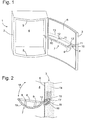
- a refrigeration device 1 is shown in a perspective view, which has a limited by a body 2 and a door 3 thermally insulated interior 4.
- the door 3 is pivotally mounted in a known manner by hinges (not shown here) on a lateral front edge of the body 2 about a vertical axis.
- An interior wall 4 facing the inner wall 6 of the door 3 has a circumferential planar frame 5, which carries a not shown here, in the closed position of the door tightly against the body 2 magnetic seal.
- the frame surrounds a large depression whose contour follows a cylindrically convex curvature on the outer surface of the door 3.
- a wire basket 7 is attached to the inner wall 6 as a storage device, which is in the form of a flat channel has.
- the wire basket 7 comprises a circumferential closed wire frame 8, which forms an upper and outer edge of the wire basket 7.
- the wire frame 8 has substantially the shape of a rectangle, wherein the longitudinal sides of the rectangle or at least the inner wall 6 facing longitudinal side is curved according to the contour of the recess of the inner wall 6.
- the wire basket 7 comprises two further in a flat, upwardly open arc extending wire bracket 10, which extend perpendicular to the wire brackets 9 , are attached at one end to the side facing away from the inner wall 6 longitudinal side of the wire frame 8 blunt and are attached to the wire brackets 9 and the inner wall near the longitudinal side of the wire frame 8 crossing.
- the wire hanger 10 divide the wire basket 7 in length into three sections, wherein the two adjoining the short sides of the wire hanger 8 sections are shorter than the middle section between the arch wires 10.
- the illustrated wire basket 7 is due to its shape, in particular for the storage of Beverage cans in a lying position.
- each wire bracket 10 At its door 3 end facing each wire bracket 10 is extended by a projecting beyond the wire frame 8 one-piece headband 11. Since the representation in Fig. 1 shows already mounted on the door 3 wire basket 7 and thus the door 3 facing ends of the bracket 11 are inserted into two arranged on the inner wall 6 openings 12, 12 ', is visible from the brackets 11 only a short section here, the rest of the part is hidden in the inner wall 6 of the door. Details on the shape of the retaining clip 11 are later in Fig. 2 shown.
- the openings 12, 12 'of the inner wall 6 are not arranged at the same height, but the pivot axis of the door facing opening 12 has a greater distance from the upper edge of the door than the opening 12', so that the wire basket 7 in the direction of the pivot axis the door 3 is slightly sloping.
- the openings 12 and 12 'from the upper edge of the door is a parallel to the latter in Fig. 1 drawn as a dotted line 13.
- FIG. 2 shows a vertical section through the wire basket 7 and the door 3 in the plane of the pivot axis of the door-facing opening 12 and the engaging wire bracket 10.
- the moisture-resistant material existing inner wall 6 of the door 3 covers an insulating material layer 14 formed of insulating foam an interior 4 of the refrigerator and protects the insulating material layer 14 from the ingress of moisture from the interior. 4
- a curved sleeve 15 is inserted into an opening 12 of the inner wall 6 and extends into the insulating material layer 14.
- a base body 16 of the sleeve 15 has the shape of a quadrant-curved tube. One end of the tube is open and carries an annular circumferential collar 19, which abuts against the interior 4 facing side of the inner wall 6. The other end of the sleeve 15 is closed.
- the tie 11 extends, as already in Fig. 1 described, the arch wire 10 over the edge of the wire basket 7 horizontally outward and is bent just after a branch from the arch wire 10 in approximately a quarter circle upwards.
- the shape and length of the retaining bow 11 follows approximately the shape of the cavity 17, so that the tie sheet 11 can be substantially completely inserted into the sleeve 15. Due to the force of gravity, which pulls the wire basket 7 down, the tether 11 is supported at an inner radius of its bend and at its end stable from the inside against an inner surface of the sleeve 15.
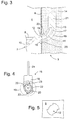
- FIG. 3 An enlarged section of Fig. 2 is in Fig. 3 shown.
- a collar 19 in the form of a flat disc, from the middle of the opening of the sleeve 15 is cut out.
- the collar 19 conforms to the interior of the 4-facing side of the inner wall 6 flat and this covers the edge of the opening 12 in its entirety. Since the base body 16 and the collar 19 completely cover the inner wall 6 of the door 3 in the region of the opening 12, the wire basket 7 does not touch the inner wall 6 of the door 3 directly, but is supported exclusively against the sleeve 15.
- two latching wings 20 are formed, which protrude from an outer surface of the sleeve 15 in the bent portion of the sleeve 15 and project as a tongue in the direction of the opening 12 on the outer surface.
- the latching wings 20 are based on isoliermaterial paragraph against the inner wall 6 from.
- the sail 21 supports the firm anchoring of the sleeve 15 in the insulating material 14, with which the door is filled with foam in a conventional manner.
- a cross section of the sleeve 15 along the plane formed by the inner wall 6 is in Fig. 4 shown.
- a hollow cylindrical wall 22 of the sleeve 15 carries on opposite outer surfaces in each case a connecting web 23, which connects the wall 22 with one of the latching wings 20.
- a front edge of the latching wing 20 is behind the cutting plane to between the front edge and the front of the cutting plane of the Fig. 4 lying and therefore only shown as a dashed outline collar 19 to leave space for the inner wall 6.
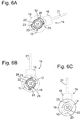
- Fig. 5 now shows a section of the inner wall 6 with the opening 12 in a frontal view.
- the opening 12 has a circular outer cross-section in which are cut on opposite sides narrow strips of a quarter-circle segment, so that the opening 12 in each case two projecting and two Has receding segment edges.
- the opening 12 forms a bayonet anchorage, the operation of which will be described below.
- An axis of rotation of the bayonet anchor extends centrally through the opening 12 and is perpendicular to the inner wall. 6
- the sleeve 15 is mounted on the inner wall 6 of the door by being inserted with the sail 21 in front from the side of the interior 4 in the opening 12 until the collar 19 abuts flat against the inner wall 6.
- the sleeve 15 is held so that the plate 21 assumes an approximately horizontal, seen from the interior 4 of the refrigerator from the right tilted position.
- FIGs. 6A, 6B and 6C Individual views during assembly of the sleeve 15 are now in Figs. 6A, 6B and 6C shown, seen from the side of the interior 4 of.
- Fig. 6A the sleeve 15 is already completely inserted into the opening 12 and held in the position described above.
- the collar 19, which bears against the inner wall 6, is here indicated for the sake of better illustration only as a dashed outline. Since the contours of the base body 16 and the sail 21 are hidden in this position behind the inner wall 6, these are also indicated only by dashed lines.
- the wall 22 of the sleeve 15 including the connecting webs 23 and the molded latching wings 20 almost fill the opening 12 and the latching wings 20 back behind the edge of the opening 12 and behind the wall 22 and the connecting webs 23 back.
- Fig. 6C shows finally the collar 19 with the concentrically arranged open front end of the cavity 17, wherein the collar covers the edges of the opening 12.
- the opening 12 may assume different shapes with regard to the segment cutouts. Of particular importance here is the fixing of the sleeve 15 in the opening 12 by a rotation of the sleeve 15 in the manner of a bayonet anchorage
- the latching wings 20 can also be spread in the form of dandruff from the on the outer wall of the base body 16, so that when they push into the opening 12 again so far to the base 16 create that the Sleeve 15 can be inserted through the opening 12, and then spread apart again to support the sleeve 15 behind the inner wall 6 against the latter.
- the opening 12 may simply be round.
Landscapes
- Engineering & Computer Science (AREA)
- Chemical & Material Sciences (AREA)
- Combustion & Propulsion (AREA)
- Physics & Mathematics (AREA)
- Mechanical Engineering (AREA)
- Thermal Sciences (AREA)
- General Engineering & Computer Science (AREA)
- Refrigerator Housings (AREA)
Applications Claiming Priority (2)
| Application Number | Priority Date | Filing Date | Title |
|---|---|---|---|
| DE200810007660 DE102008007660A1 (de) | 2008-02-06 | 2008-02-06 | Kältegerätetür mit Ablagevorrichtung |
| PCT/EP2009/050960 WO2009098156A2 (de) | 2008-02-06 | 2009-01-28 | Kältegerätetür mit ablagevorrichtung |
Publications (2)
| Publication Number | Publication Date |
|---|---|
| EP2240732A2 EP2240732A2 (de) | 2010-10-20 |
| EP2240732B1 true EP2240732B1 (de) | 2016-08-24 |
Family
ID=40847182
Family Applications (1)
| Application Number | Title | Priority Date | Filing Date |
|---|---|---|---|
| EP09709024.5A Active EP2240732B1 (de) | 2008-02-06 | 2009-01-28 | Kältegerätetür mit ablagevorrichtung |
Country Status (6)
| Country | Link |
|---|---|
| EP (1) | EP2240732B1 (pl) |
| CN (1) | CN101939606A (pl) |
| DE (1) | DE102008007660A1 (pl) |
| PL (1) | PL2240732T3 (pl) |
| RU (1) | RU2494321C2 (pl) |
| WO (1) | WO2009098156A2 (pl) |
Families Citing this family (1)
| Publication number | Priority date | Publication date | Assignee | Title |
|---|---|---|---|---|
| DE102009047245A1 (de) * | 2009-11-27 | 2011-06-01 | BSH Bosch und Siemens Hausgeräte GmbH | Kältegerät |
Family Cites Families (5)
| Publication number | Priority date | Publication date | Assignee | Title |
|---|---|---|---|---|
| US2074438A (en) | 1934-04-14 | 1937-03-23 | Seeger Refrigerator Co | Refrigerator door basket |
| DE1861044U (de) * | 1962-05-11 | 1962-10-31 | Licentia Gmbh | Halterung fuer in der tuerinnenplatte von kuehlschraenken abzustellende kuehlgueter, insbesondere flaschen. |
| US3378219A (en) | 1967-01-13 | 1968-04-16 | Illinois Tool Works | Plastic fastener |
| KR0136407B1 (ko) * | 1995-08-04 | 1998-07-01 | 배순훈 | 냉장고 포켓구조 |
| US6220684B1 (en) * | 2000-07-13 | 2001-04-24 | Maytag Corporation | Adjustable retainer assembly for a refrigerator door shelf |
-
2008
- 2008-02-06 DE DE200810007660 patent/DE102008007660A1/de not_active Withdrawn
-
2009
- 2009-01-28 WO PCT/EP2009/050960 patent/WO2009098156A2/de not_active Ceased
- 2009-01-28 RU RU2010135410/13A patent/RU2494321C2/ru active
- 2009-01-28 PL PL09709024T patent/PL2240732T3/pl unknown
- 2009-01-28 CN CN2009801042070A patent/CN101939606A/zh active Pending
- 2009-01-28 EP EP09709024.5A patent/EP2240732B1/de active Active
Also Published As
| Publication number | Publication date |
|---|---|
| CN101939606A (zh) | 2011-01-05 |
| RU2010135410A (ru) | 2012-03-20 |
| EP2240732A2 (de) | 2010-10-20 |
| WO2009098156A2 (de) | 2009-08-13 |
| DE102008007660A1 (de) | 2009-08-13 |
| PL2240732T3 (pl) | 2017-01-31 |
| RU2494321C2 (ru) | 2013-09-27 |
| WO2009098156A3 (de) | 2009-12-03 |
Similar Documents
| Publication | Publication Date | Title |
|---|---|---|
| EP2122278B1 (de) | Kältegerät mit an einer schiene aufgehängten fachböden | |
| DE60003891T2 (de) | Befestigungsvorrichtung mit einem an einer wand abgehängten stab | |
| DE2446079C2 (de) | Basiskonstruktion für eine Trennwand | |
| EP2606300B1 (de) | Kältegerät mit ablagefläche zur ablage von kühlgut | |
| DE4023284A1 (de) | Einstueckiger zuggriff mit einrastwirkung | |
| EP2240732B1 (de) | Kältegerätetür mit ablagevorrichtung | |
| EP1526039B1 (de) | Laderaumabdeckung mit Verzurrmitteln | |
| WO2003016802A1 (de) | Kältegerät mit herausziehbarem lagergutträger | |
| DE102009035657A1 (de) | Träger für ein Zubehörteil einer Spüle, Spülenzubehöranordnung und Spülenanordnung | |
| AT515381A2 (de) | Unterdecke, welche ein Trageprofil und daran eingehängte Paneele aufweist | |
| DE102006014374A1 (de) | Aufhängungssystem für Fachböden | |
| DE202007007024U1 (de) | Anordnung an Behältern landwirtschaftlicher Verteilmaschinen | |
| DE2641606A1 (de) | Wandkonstruktion | |
| EP3537077B1 (de) | Kühlgutabstellfach mit l-förmigen rahmen, tür sowie haushaltskältegerät | |
| EP2156117A1 (de) | Schiene für ein aufhängungssystem | |
| DE102010023924A1 (de) | Schalungselement | |
| DE8620871U1 (de) | Haltevorrichtung, insbesondere für Küchengeräte | |
| DE19807724C2 (de) | Zweiteiliges Wandskihalterungssystem | |
| DE8619327U1 (de) | Handgepäckablage, insbesondere für Fahrzeuge des öffentlichen Massenverkehrs | |
| DE1025441B (de) | Gepaeckablage, insbesondere in Fahrzeugen fuer den Personenverkehr | |
| DE102018104809A1 (de) | Fachboden und Fachbodenanordnung | |
| EP3530165A1 (de) | Korb für reinigungs- und pflegeprodukte | |
| DE202004000123U1 (de) | Kabeltragvorrichtung | |
| DE202016102190U1 (de) | Ampelhaken für Gabionen | |
| DE29915752U1 (de) | Kleiderbügel |
Legal Events
| Date | Code | Title | Description |
|---|---|---|---|
| PUAI | Public reference made under article 153(3) epc to a published international application that has entered the european phase |
Free format text: ORIGINAL CODE: 0009012 |
|
| 17P | Request for examination filed |
Effective date: 20100906 |
|
| AK | Designated contracting states |
Kind code of ref document: A2 Designated state(s): AT BE BG CH CY CZ DE DK EE ES FI FR GB GR HR HU IE IS IT LI LT LU LV MC MK MT NL NO PL PT RO SE SI SK TR |
|
| DAX | Request for extension of the european patent (deleted) | ||
| RAP1 | Party data changed (applicant data changed or rights of an application transferred) |
Owner name: BSH HAUSGERAETE GMBH |
|
| 17Q | First examination report despatched |
Effective date: 20151210 |
|
| GRAP | Despatch of communication of intention to grant a patent |
Free format text: ORIGINAL CODE: EPIDOSNIGR1 |
|
| INTG | Intention to grant announced |
Effective date: 20160506 |
|
| GRAS | Grant fee paid |
Free format text: ORIGINAL CODE: EPIDOSNIGR3 |
|
| GRAA | (expected) grant |
Free format text: ORIGINAL CODE: 0009210 |
|
| AK | Designated contracting states |
Kind code of ref document: B1 Designated state(s): AT BE BG CH CY CZ DE DK EE ES FI FR GB GR HR HU IE IS IT LI LT LU LV MC MK MT NL NO PL PT RO SE SI SK TR |
|
| REG | Reference to a national code |
Ref country code: GB Ref legal event code: FG4D Free format text: NOT ENGLISH |
|
| REG | Reference to a national code |
Ref country code: CH Ref legal event code: EP |
|
| REG | Reference to a national code |
Ref country code: AT Ref legal event code: REF Ref document number: 823479 Country of ref document: AT Kind code of ref document: T Effective date: 20160915 |
|
| REG | Reference to a national code |
Ref country code: IE Ref legal event code: FG4D Free format text: LANGUAGE OF EP DOCUMENT: GERMAN |
|
| REG | Reference to a national code |
Ref country code: DE Ref legal event code: R096 Ref document number: 502009012993 Country of ref document: DE |
|
| REG | Reference to a national code |
Ref country code: LT Ref legal event code: MG4D |
|
| REG | Reference to a national code |
Ref country code: NL Ref legal event code: MP Effective date: 20160824 |
|
| PG25 | Lapsed in a contracting state [announced via postgrant information from national office to epo] |
Ref country code: FI Free format text: LAPSE BECAUSE OF FAILURE TO SUBMIT A TRANSLATION OF THE DESCRIPTION OR TO PAY THE FEE WITHIN THE PRESCRIBED TIME-LIMIT Effective date: 20160824 Ref country code: NL Free format text: LAPSE BECAUSE OF FAILURE TO SUBMIT A TRANSLATION OF THE DESCRIPTION OR TO PAY THE FEE WITHIN THE PRESCRIBED TIME-LIMIT Effective date: 20160824 Ref country code: HR Free format text: LAPSE BECAUSE OF FAILURE TO SUBMIT A TRANSLATION OF THE DESCRIPTION OR TO PAY THE FEE WITHIN THE PRESCRIBED TIME-LIMIT Effective date: 20160824 Ref country code: LT Free format text: LAPSE BECAUSE OF FAILURE TO SUBMIT A TRANSLATION OF THE DESCRIPTION OR TO PAY THE FEE WITHIN THE PRESCRIBED TIME-LIMIT Effective date: 20160824 Ref country code: NO Free format text: LAPSE BECAUSE OF FAILURE TO SUBMIT A TRANSLATION OF THE DESCRIPTION OR TO PAY THE FEE WITHIN THE PRESCRIBED TIME-LIMIT Effective date: 20161124 |
|
| PG25 | Lapsed in a contracting state [announced via postgrant information from national office to epo] |
Ref country code: LV Free format text: LAPSE BECAUSE OF FAILURE TO SUBMIT A TRANSLATION OF THE DESCRIPTION OR TO PAY THE FEE WITHIN THE PRESCRIBED TIME-LIMIT Effective date: 20160824 Ref country code: ES Free format text: LAPSE BECAUSE OF FAILURE TO SUBMIT A TRANSLATION OF THE DESCRIPTION OR TO PAY THE FEE WITHIN THE PRESCRIBED TIME-LIMIT Effective date: 20160824 Ref country code: GR Free format text: LAPSE BECAUSE OF FAILURE TO SUBMIT A TRANSLATION OF THE DESCRIPTION OR TO PAY THE FEE WITHIN THE PRESCRIBED TIME-LIMIT Effective date: 20161125 Ref country code: PT Free format text: LAPSE BECAUSE OF FAILURE TO SUBMIT A TRANSLATION OF THE DESCRIPTION OR TO PAY THE FEE WITHIN THE PRESCRIBED TIME-LIMIT Effective date: 20161226 Ref country code: SE Free format text: LAPSE BECAUSE OF FAILURE TO SUBMIT A TRANSLATION OF THE DESCRIPTION OR TO PAY THE FEE WITHIN THE PRESCRIBED TIME-LIMIT Effective date: 20160824 |
|
| PG25 | Lapsed in a contracting state [announced via postgrant information from national office to epo] |
Ref country code: RO Free format text: LAPSE BECAUSE OF FAILURE TO SUBMIT A TRANSLATION OF THE DESCRIPTION OR TO PAY THE FEE WITHIN THE PRESCRIBED TIME-LIMIT Effective date: 20160824 Ref country code: EE Free format text: LAPSE BECAUSE OF FAILURE TO SUBMIT A TRANSLATION OF THE DESCRIPTION OR TO PAY THE FEE WITHIN THE PRESCRIBED TIME-LIMIT Effective date: 20160824 |
|
| REG | Reference to a national code |
Ref country code: DE Ref legal event code: R097 Ref document number: 502009012993 Country of ref document: DE |
|
| PG25 | Lapsed in a contracting state [announced via postgrant information from national office to epo] |
Ref country code: CZ Free format text: LAPSE BECAUSE OF FAILURE TO SUBMIT A TRANSLATION OF THE DESCRIPTION OR TO PAY THE FEE WITHIN THE PRESCRIBED TIME-LIMIT Effective date: 20160824 Ref country code: BE Free format text: LAPSE BECAUSE OF NON-PAYMENT OF DUE FEES Effective date: 20170131 Ref country code: DK Free format text: LAPSE BECAUSE OF FAILURE TO SUBMIT A TRANSLATION OF THE DESCRIPTION OR TO PAY THE FEE WITHIN THE PRESCRIBED TIME-LIMIT Effective date: 20160824 Ref country code: SK Free format text: LAPSE BECAUSE OF FAILURE TO SUBMIT A TRANSLATION OF THE DESCRIPTION OR TO PAY THE FEE WITHIN THE PRESCRIBED TIME-LIMIT Effective date: 20160824 Ref country code: BG Free format text: LAPSE BECAUSE OF FAILURE TO SUBMIT A TRANSLATION OF THE DESCRIPTION OR TO PAY THE FEE WITHIN THE PRESCRIBED TIME-LIMIT Effective date: 20161124 |
|
| PLBE | No opposition filed within time limit |
Free format text: ORIGINAL CODE: 0009261 |
|
| STAA | Information on the status of an ep patent application or granted ep patent |
Free format text: STATUS: NO OPPOSITION FILED WITHIN TIME LIMIT |
|
| 26N | No opposition filed |
Effective date: 20170526 |
|
| PG25 | Lapsed in a contracting state [announced via postgrant information from national office to epo] |
Ref country code: SI Free format text: LAPSE BECAUSE OF FAILURE TO SUBMIT A TRANSLATION OF THE DESCRIPTION OR TO PAY THE FEE WITHIN THE PRESCRIBED TIME-LIMIT Effective date: 20160824 |
|
| REG | Reference to a national code |
Ref country code: CH Ref legal event code: PL |
|
| GBPC | Gb: european patent ceased through non-payment of renewal fee |
Effective date: 20170128 |
|
| PG25 | Lapsed in a contracting state [announced via postgrant information from national office to epo] |
Ref country code: MC Free format text: LAPSE BECAUSE OF FAILURE TO SUBMIT A TRANSLATION OF THE DESCRIPTION OR TO PAY THE FEE WITHIN THE PRESCRIBED TIME-LIMIT Effective date: 20160824 |
|
| REG | Reference to a national code |
Ref country code: FR Ref legal event code: ST Effective date: 20170929 |
|
| PG25 | Lapsed in a contracting state [announced via postgrant information from national office to epo] |
Ref country code: LI Free format text: LAPSE BECAUSE OF NON-PAYMENT OF DUE FEES Effective date: 20170131 Ref country code: FR Free format text: LAPSE BECAUSE OF NON-PAYMENT OF DUE FEES Effective date: 20170131 Ref country code: CH Free format text: LAPSE BECAUSE OF NON-PAYMENT OF DUE FEES Effective date: 20170131 |
|
| REG | Reference to a national code |
Ref country code: IE Ref legal event code: MM4A |
|
| PG25 | Lapsed in a contracting state [announced via postgrant information from national office to epo] |
Ref country code: LU Free format text: LAPSE BECAUSE OF NON-PAYMENT OF DUE FEES Effective date: 20170128 Ref country code: GB Free format text: LAPSE BECAUSE OF NON-PAYMENT OF DUE FEES Effective date: 20170128 |
|
| REG | Reference to a national code |
Ref country code: BE Ref legal event code: MM Effective date: 20170131 |
|
| PG25 | Lapsed in a contracting state [announced via postgrant information from national office to epo] |
Ref country code: IE Free format text: LAPSE BECAUSE OF NON-PAYMENT OF DUE FEES Effective date: 20170128 |
|
| REG | Reference to a national code |
Ref country code: AT Ref legal event code: MM01 Ref document number: 823479 Country of ref document: AT Kind code of ref document: T Effective date: 20170128 |
|
| PG25 | Lapsed in a contracting state [announced via postgrant information from national office to epo] |
Ref country code: AT Free format text: LAPSE BECAUSE OF NON-PAYMENT OF DUE FEES Effective date: 20170128 |
|
| PG25 | Lapsed in a contracting state [announced via postgrant information from national office to epo] |
Ref country code: MT Free format text: LAPSE BECAUSE OF FAILURE TO SUBMIT A TRANSLATION OF THE DESCRIPTION OR TO PAY THE FEE WITHIN THE PRESCRIBED TIME-LIMIT Effective date: 20160824 |
|
| PG25 | Lapsed in a contracting state [announced via postgrant information from national office to epo] |
Ref country code: HU Free format text: LAPSE BECAUSE OF FAILURE TO SUBMIT A TRANSLATION OF THE DESCRIPTION OR TO PAY THE FEE WITHIN THE PRESCRIBED TIME-LIMIT; INVALID AB INITIO Effective date: 20090128 |
|
| PG25 | Lapsed in a contracting state [announced via postgrant information from national office to epo] |
Ref country code: CY Free format text: LAPSE BECAUSE OF NON-PAYMENT OF DUE FEES Effective date: 20160824 |
|
| PG25 | Lapsed in a contracting state [announced via postgrant information from national office to epo] |
Ref country code: MK Free format text: LAPSE BECAUSE OF FAILURE TO SUBMIT A TRANSLATION OF THE DESCRIPTION OR TO PAY THE FEE WITHIN THE PRESCRIBED TIME-LIMIT Effective date: 20160824 |
|
| PG25 | Lapsed in a contracting state [announced via postgrant information from national office to epo] |
Ref country code: IS Free format text: LAPSE BECAUSE OF FAILURE TO SUBMIT A TRANSLATION OF THE DESCRIPTION OR TO PAY THE FEE WITHIN THE PRESCRIBED TIME-LIMIT Effective date: 20161224 |
|
| PGFP | Annual fee paid to national office [announced via postgrant information from national office to epo] |
Ref country code: TR Payment date: 20210121 Year of fee payment: 13 |
|
| PGFP | Annual fee paid to national office [announced via postgrant information from national office to epo] |
Ref country code: DE Payment date: 20220131 Year of fee payment: 14 |
|
| PGFP | Annual fee paid to national office [announced via postgrant information from national office to epo] |
Ref country code: PL Payment date: 20220117 Year of fee payment: 14 Ref country code: IT Payment date: 20220124 Year of fee payment: 14 |
|
| REG | Reference to a national code |
Ref country code: DE Ref legal event code: R119 Ref document number: 502009012993 Country of ref document: DE |
|
| PG25 | Lapsed in a contracting state [announced via postgrant information from national office to epo] |
Ref country code: DE Free format text: LAPSE BECAUSE OF NON-PAYMENT OF DUE FEES Effective date: 20230801 |
|
| PG25 | Lapsed in a contracting state [announced via postgrant information from national office to epo] |
Ref country code: IT Free format text: LAPSE BECAUSE OF NON-PAYMENT OF DUE FEES Effective date: 20230128 |
|
| PG25 | Lapsed in a contracting state [announced via postgrant information from national office to epo] |
Ref country code: PL Free format text: LAPSE BECAUSE OF NON-PAYMENT OF DUE FEES Effective date: 20230128 |