EP2240732B1 - Kältegerätetür mit ablagevorrichtung - Google Patents
Kältegerätetür mit ablagevorrichtung Download PDFInfo
- Publication number
- EP2240732B1 EP2240732B1 EP09709024.5A EP09709024A EP2240732B1 EP 2240732 B1 EP2240732 B1 EP 2240732B1 EP 09709024 A EP09709024 A EP 09709024A EP 2240732 B1 EP2240732 B1 EP 2240732B1
- Authority
- EP
- European Patent Office
- Prior art keywords
- door
- wall
- sleeve
- refrigeration device
- storage unit
- Prior art date
- Legal status (The legal status is an assumption and is not a legal conclusion. Google has not performed a legal analysis and makes no representation as to the accuracy of the status listed.)
- Active
Links
Images
Classifications
-
- F—MECHANICAL ENGINEERING; LIGHTING; HEATING; WEAPONS; BLASTING
- F25—REFRIGERATION OR COOLING; COMBINED HEATING AND REFRIGERATION SYSTEMS; HEAT PUMP SYSTEMS; MANUFACTURE OR STORAGE OF ICE; LIQUEFACTION SOLIDIFICATION OF GASES
- F25D—REFRIGERATORS; COLD ROOMS; ICE-BOXES; COOLING OR FREEZING APPARATUS NOT OTHERWISE PROVIDED FOR
- F25D23/00—General constructional features
- F25D23/02—Doors; Covers
- F25D23/04—Doors; Covers with special compartments, e.g. butter conditioners
-
- F—MECHANICAL ENGINEERING; LIGHTING; HEATING; WEAPONS; BLASTING
- F25—REFRIGERATION OR COOLING; COMBINED HEATING AND REFRIGERATION SYSTEMS; HEAT PUMP SYSTEMS; MANUFACTURE OR STORAGE OF ICE; LIQUEFACTION SOLIDIFICATION OF GASES
- F25D—REFRIGERATORS; COLD ROOMS; ICE-BOXES; COOLING OR FREEZING APPARATUS NOT OTHERWISE PROVIDED FOR
- F25D23/00—General constructional features
- F25D23/06—Walls
- F25D23/065—Details
- F25D23/067—Supporting elements
Definitions
- the present invention relates to a refrigeration appliance door having a storage device arranged on an inner wall of the door.
- Such storage devices often referred to as door racks are usually attached to an inner wall of the door by, for example, the storage device is mounted on fixed to the inner wall support rails.
- the storage device is mounted on fixed to the inner wall support rails.
- Such an arrangement requires effort during the construction and assembly of the refrigeration device to suitably attach the carrier rails to the inner wall and to design it so that the storage devices receive sufficient load capacity.
- the storage device can be locked between two wall projections bounding the inner wall of the door on both sides.
- the storage device can be locked between two wall projections bounding the inner wall of the door on both sides.
- FIG. 1 Another attachment of a storage device to a refrigerator door is known from the patent US 2 074 438 known.
- the storage device in the form of a mesh basket has on one of the door facing the rear side two latching hooks, which each engage in an opening in the inner wall of the door. Since the insulating filling of the door is sensitive to moisture, the opening is insulator material deposited with an insert, which protects the insulating filling against moisture penetration.
- JP H05-180557 discloses a refrigeration device having a dented area in a surface of the refrigeration container.
- a bolt with a Ablsgeteil for a flat bottom, a flange and an insertion part is inserted into a projecting part. This projecting part is inserted in an opening in the recessed area.
- DE 1601891 discloses a refrigerator door according to the preamble of claim 1.
- a refrigeration device characterized in that in a refrigerator door with a moisture-resistant inner wall, which covers a moisture-sensitive insulation filling the door, and with a releasably suspended on an opening of the inner wall storage device inserted into the opening sleeve closes the opening and a headband of the storage device against an inner surface of the sleeve supported, the sleeve can seal the opening in the inner wall and protect the insulating filling from moisture while distributing the weight of the storage device to a larger contact surface with the inner wall, as when the storage device is suspended directly on the inner wall.
- the insulating material is an expanded inside the door foam, it can firmly enclose the sleeve, whereby on the one hand a permanent fixation of the sleeve is achieved and on the other hand, a part of the load on the sleeve weight of the storage device introduced into the foam and the inner wall are relieved can.
- this arrangement has the advantage that the manufacture of a door according to the invention differs from the production of a door without a holder for a storage device only in a few simple steps, so that in particular for molding the inner wall for both tools can be used.
- the manufacture of the door according to the invention only the required openings in the inner wall need to be additionally created and a corresponding sleeve inserted into each of them.
- the sleeve can be locked by a bayonet anchorage on the inner wall of the door, then the sleeve can be mounted in a very simple manner and without additional fasteners in the opening and fixed there so that the position of the sleeve can be securely maintained even during the foaming of the door can.
- An assembly of the sleeve can be carried out very easily by the sleeve is inserted in an orientation predetermined by the shape of the opening through the opening and transferred by a subsequent rotation of the sleeve in a final position.
- a portion of the sleeve has the shape of a curved tube. Since in a mounted storage device inserted into the interior of the sleeve and the curved shape of the sleeve adapted support bracket is supported against the inner surface of the sleeve and the end of the retaining bracket extends beyond the curvature, can also during movement of the door by a user of the device reliably prevents the headband from accidentally coming off the sleeve.
- the depositing device can be hung on the door safely, without requiring a further support point on the inner wall below the sleeves. This makes this type of anchoring particularly suitable for a storage device with non-cuboid container shape.
- the collar during the foaming of the door can protect the edge of the opening against inadvertent escape of insulating foam.
- the collar can seal the opening to an inside of the door so that the underlying insulating material layer is reliably protected against moisture penetration.
- the collar can cover the opening, so that the appearance of the door on its inside is not disturbed and an attractive design can be effected.
- a particularly firm anchoring of the sleeve within the insulating material layer can be achieved if the sleeve carries at one of the depositing device remote from the second end projecting into the insulating material in the wing.
- the wing can additionally absorb and distribute the forces acting on the sleeve of the supporting against the inner surface of the sleeve retaining bracket. This can be favored in particular by the orientation of the wing in the plane of the axis of rotation of the bayonet anchorage.
- the storage device in particular has the shape of a channel with a round bottom, then the sleeve according to the invention, the storage device stable to the door anchor without the storage device further stabilizing elements are required, which would have to be supported for example against the inner wall of the door.
- a gutter can store refrigerated goods of a round shape, for example beverage cans, safely lying down.
- At least one side of the storage device facing the inner wall can follow the curvature.
- the shape of the storage device can be optimally adapted to the spatial conditions in order to make good use of the space on the inside of the door can.
- the described design flexibility can be particularly well exploited, so that an attractive design without disturbing fasteners can be made possible.
- the headband extends a lattice strut of the wire basket in one piece.
- the production of the wire basket can be simplified because no additional fastening components must be attached to the wire basket.
- the bottom of the storage device slopes down in a direction parallel to the inner wall of the door, it can be prevented from slipping on the storage device under the influence of a centrifugal force occurring when opening or closing the door and falling from the storage device.
- the storage device should be downhill to the pivot axis of the door.
- the inner wall of the door has at least two openings for holders for attaching a storage device, wherein the openings have different distances from an upper edge of the inner wall, the sloping arrangement of the bottom of the storage device can be achieved very easily, without the storage device itself be adjusted got to.
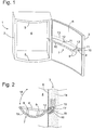
- a refrigeration device 1 is shown in a perspective view, which has a limited by a body 2 and a door 3 thermally insulated interior 4.
- the door 3 is pivotally mounted in a known manner by hinges (not shown here) on a lateral front edge of the body 2 about a vertical axis.
- An interior wall 4 facing the inner wall 6 of the door 3 has a circumferential planar frame 5, which carries a not shown here, in the closed position of the door tightly against the body 2 magnetic seal.
- the frame surrounds a large depression whose contour follows a cylindrically convex curvature on the outer surface of the door 3.
- a wire basket 7 is attached to the inner wall 6 as a storage device, which is in the form of a flat channel has.
- the wire basket 7 comprises a circumferential closed wire frame 8, which forms an upper and outer edge of the wire basket 7.
- the wire frame 8 has substantially the shape of a rectangle, wherein the longitudinal sides of the rectangle or at least the inner wall 6 facing longitudinal side is curved according to the contour of the recess of the inner wall 6.
- the wire basket 7 comprises two further in a flat, upwardly open arc extending wire bracket 10, which extend perpendicular to the wire brackets 9 , are attached at one end to the side facing away from the inner wall 6 longitudinal side of the wire frame 8 blunt and are attached to the wire brackets 9 and the inner wall near the longitudinal side of the wire frame 8 crossing.
- the wire hanger 10 divide the wire basket 7 in length into three sections, wherein the two adjoining the short sides of the wire hanger 8 sections are shorter than the middle section between the arch wires 10.
- the illustrated wire basket 7 is due to its shape, in particular for the storage of Beverage cans in a lying position.
- each wire bracket 10 At its door 3 end facing each wire bracket 10 is extended by a projecting beyond the wire frame 8 one-piece headband 11. Since the representation in Fig. 1 shows already mounted on the door 3 wire basket 7 and thus the door 3 facing ends of the bracket 11 are inserted into two arranged on the inner wall 6 openings 12, 12 ', is visible from the brackets 11 only a short section here, the rest of the part is hidden in the inner wall 6 of the door. Details on the shape of the retaining clip 11 are later in Fig. 2 shown.
- the openings 12, 12 'of the inner wall 6 are not arranged at the same height, but the pivot axis of the door facing opening 12 has a greater distance from the upper edge of the door than the opening 12', so that the wire basket 7 in the direction of the pivot axis the door 3 is slightly sloping.
- the openings 12 and 12 'from the upper edge of the door is a parallel to the latter in Fig. 1 drawn as a dotted line 13.
- FIG. 2 shows a vertical section through the wire basket 7 and the door 3 in the plane of the pivot axis of the door-facing opening 12 and the engaging wire bracket 10.
- the moisture-resistant material existing inner wall 6 of the door 3 covers an insulating material layer 14 formed of insulating foam an interior 4 of the refrigerator and protects the insulating material layer 14 from the ingress of moisture from the interior. 4
- a curved sleeve 15 is inserted into an opening 12 of the inner wall 6 and extends into the insulating material layer 14.
- a base body 16 of the sleeve 15 has the shape of a quadrant-curved tube. One end of the tube is open and carries an annular circumferential collar 19, which abuts against the interior 4 facing side of the inner wall 6. The other end of the sleeve 15 is closed.
- the tie 11 extends, as already in Fig. 1 described, the arch wire 10 over the edge of the wire basket 7 horizontally outward and is bent just after a branch from the arch wire 10 in approximately a quarter circle upwards.
- the shape and length of the retaining bow 11 follows approximately the shape of the cavity 17, so that the tie sheet 11 can be substantially completely inserted into the sleeve 15. Due to the force of gravity, which pulls the wire basket 7 down, the tether 11 is supported at an inner radius of its bend and at its end stable from the inside against an inner surface of the sleeve 15.
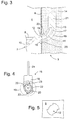
- FIG. 3 An enlarged section of Fig. 2 is in Fig. 3 shown.
- a collar 19 in the form of a flat disc, from the middle of the opening of the sleeve 15 is cut out.
- the collar 19 conforms to the interior of the 4-facing side of the inner wall 6 flat and this covers the edge of the opening 12 in its entirety. Since the base body 16 and the collar 19 completely cover the inner wall 6 of the door 3 in the region of the opening 12, the wire basket 7 does not touch the inner wall 6 of the door 3 directly, but is supported exclusively against the sleeve 15.
- two latching wings 20 are formed, which protrude from an outer surface of the sleeve 15 in the bent portion of the sleeve 15 and project as a tongue in the direction of the opening 12 on the outer surface.
- the latching wings 20 are based on isoliermaterial paragraph against the inner wall 6 from.
- the sail 21 supports the firm anchoring of the sleeve 15 in the insulating material 14, with which the door is filled with foam in a conventional manner.
- a cross section of the sleeve 15 along the plane formed by the inner wall 6 is in Fig. 4 shown.
- a hollow cylindrical wall 22 of the sleeve 15 carries on opposite outer surfaces in each case a connecting web 23, which connects the wall 22 with one of the latching wings 20.
- a front edge of the latching wing 20 is behind the cutting plane to between the front edge and the front of the cutting plane of the Fig. 4 lying and therefore only shown as a dashed outline collar 19 to leave space for the inner wall 6.
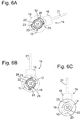
- Fig. 5 now shows a section of the inner wall 6 with the opening 12 in a frontal view.
- the opening 12 has a circular outer cross-section in which are cut on opposite sides narrow strips of a quarter-circle segment, so that the opening 12 in each case two projecting and two Has receding segment edges.
- the opening 12 forms a bayonet anchorage, the operation of which will be described below.
- An axis of rotation of the bayonet anchor extends centrally through the opening 12 and is perpendicular to the inner wall. 6
- the sleeve 15 is mounted on the inner wall 6 of the door by being inserted with the sail 21 in front from the side of the interior 4 in the opening 12 until the collar 19 abuts flat against the inner wall 6.
- the sleeve 15 is held so that the plate 21 assumes an approximately horizontal, seen from the interior 4 of the refrigerator from the right tilted position.
- FIGs. 6A, 6B and 6C Individual views during assembly of the sleeve 15 are now in Figs. 6A, 6B and 6C shown, seen from the side of the interior 4 of.
- Fig. 6A the sleeve 15 is already completely inserted into the opening 12 and held in the position described above.
- the collar 19, which bears against the inner wall 6, is here indicated for the sake of better illustration only as a dashed outline. Since the contours of the base body 16 and the sail 21 are hidden in this position behind the inner wall 6, these are also indicated only by dashed lines.
- the wall 22 of the sleeve 15 including the connecting webs 23 and the molded latching wings 20 almost fill the opening 12 and the latching wings 20 back behind the edge of the opening 12 and behind the wall 22 and the connecting webs 23 back.
- Fig. 6C shows finally the collar 19 with the concentrically arranged open front end of the cavity 17, wherein the collar covers the edges of the opening 12.
- the opening 12 may assume different shapes with regard to the segment cutouts. Of particular importance here is the fixing of the sleeve 15 in the opening 12 by a rotation of the sleeve 15 in the manner of a bayonet anchorage
- the latching wings 20 can also be spread in the form of dandruff from the on the outer wall of the base body 16, so that when they push into the opening 12 again so far to the base 16 create that the Sleeve 15 can be inserted through the opening 12, and then spread apart again to support the sleeve 15 behind the inner wall 6 against the latter.
- the opening 12 may simply be round.
Landscapes
- Engineering & Computer Science (AREA)
- Chemical & Material Sciences (AREA)
- Combustion & Propulsion (AREA)
- Physics & Mathematics (AREA)
- Mechanical Engineering (AREA)
- Thermal Sciences (AREA)
- General Engineering & Computer Science (AREA)
- Refrigerator Housings (AREA)
Description
- Die vorliegende Erfindung betrifft eine Kältegerätetür mit einer an einer Innenwand der Tür angeordneten Ablagevorrichtung.
- Derartige Ablagevorrichtungen, häufig auch als Türabsteller bezeichnet, werden normalerweise an einer Innenwand der Tür angebracht, indem beispielsweise die Ablagevorrichtung an auf der Innenwand befestigten Trägerschienen eingehängt wird. Eine solche Anordnung erfordert Aufwand während der Konstruktion und Montage des Kältegeräts, um die Trägerschienen in geeigneter Weise an der Innenwand anzubringen und so auszulegen, dass die Ablagevorrichtungen genügend Belastbarkeit erhalten.
- Alternativ hierzu kann die Ablagevorrichtung auch zwischen zwei die Innenwand der Tür an beiden Seiten begrenzenden Wandvorsprüngen verrastet werden. Nicht alle Kältegerätemodelle weisen jedoch derartige Wandvorsprünge auf, so dass die Anwendbarkeit dieser Anordnung begrenzt ist.
- Eine weitere Befestigung einer Ablagevorrichtung an einer Kältegerätetür ist aus der Patentschrift
US 2 074 438 bekannt. Die Ablagevorrichtung in Form eines Gitterkorbs weist an einer der Tür zugewandten Rückseite zwei Rasthaken auf, die jeweils in eine Öffnung in der Innenwand der Tür eingreifen. Da die Isolierfüllung der Tür feuchtigkeitsempfindlich ist, ist die Öffnung isoliermaterialseitig mit einem Einlegeteil hinterlegt, welches die Isolierfüllung gegen eindringende Feuchtigkeit schützt. - Die Fertigung dieser bekannten Tür ist aufwändig. Zum einen muss die Innenwand kräftig genug sein, um das Gewicht der Ablagevorrichtung zu tragen, das konzentriert auf die Kontaktfläche zwischen Haken und Rand der Öffnung der Innenwand in letztere eingeleitet wird. Zum anderen müssen Aussparungen im Isolationsmaterial so vorgefertigt sein, dass die an der Innenwand vormontierten Einlegeteile sich in die Aussparungen einfügen.
-
JP H05-180557 -
DE 1601891 offenbart eine Kältegerätatür gemäß dem Oberbegriff des Anspruchs 1. - Es ist daher die Aufgabe der vorliegenden Erfindung, eine Kältegerätetür zu schaffen, welche eine einfach zu fertigende und auch bei geringer Stärke der Innenwand tragfähige Anordnung zur Anbringung einer Ablagevorrichtung bereitstellt.
- Die Aufgabe wird durch eine Kältegerätetur gemäß Anspruch 1 gelöst. Dadurch, dass bei einer Kältegerätetür mit einer feuchtigkeitsbeständigen Innenwand, welche eine feuchtigkeitsempfindliche Isolierfüllung der Tür überdeckt, und mit einer an einer Öffnung der Innenwand lösbar aufgehängten Ablagevorrichtung eine in die Öffnung eingesteckte Hülse die Öffnung verschließt und sich ein Haltebügel der Ablagevorrichtung gegen eine Innenfläche der Hülse abstützt, kann die Hülse die Öffnung in der Innenwand abdichten und die Isolierfüllung vor Feuchtigkeit schützen und gleichzeitig das Gewicht der Ablagevorrichtung auf eine größere Kontaktfläche zur Innenwand verteilen, als wenn die Ablagevorrichtung direkt an der Innenwand aufgehängt ist.
- Wenn das Isoliermaterial ein im Innern der Tür expandierter Schaum ist, kann es die Hülse fest umschließen, wodurch einerseits eine dauerhafte Fixierung der Hülse erreicht wird und andererseits auch ein Teil des auf der Hülse lastenden Gewichts der Ablagevorrichtung in den Schaum eingeleitet und die Innenwand entlastet werden kann.
- Aus fertigungstechnischer Sicht bietet diese Anordnung den Vorteil, dass die Fertigung einer erfindungsgemäßen Tür sich von der Fertigung einer Tür ohne Halterung für eine Ablagevorrichtung nur in wenigen einfachen Schritten unterscheidet, so dass insbesondere zum Formen der Innenwand für beide dieselben Werkzeuge verwendet werden können. Zur Fertigung der erfindungsgemäßen Tür müssen lediglich zusätzlich die benötigten Öffnungen in der Innenwand geschaffen und in jede von ihnen eine entsprechende Hülse eingeführt werden.
- Wenn die Hülse durch eine Bajonettverankerung an der Innenwand der Tür verrastbar ist, so kann die Hülse in sehr einfacher Weise und ohne zusätzliche Befestigungsmittel in der Öffnung montiert und dort so fixiert werden, dass die Position der Hülse auch während des Ausschäumens der Tür sicher beibehalten werden kann. Eine Montage der Hülse kann sehr leicht durchgeführt werden, indem die Hülse in einer durch die Form der Öffnung vorgegebenen Orientierung durch die Öffnung hindurch eingeführt und durch eine anschließende Rotation der Hülse in eine endgültige Stellung überführt wird.
- Für einen sicheren Sitz des Haltebügels in der Hülse besitzt erfindungsgemäß ein Abschnitt der Hülse die Form eines gekrümmten Rohres. Da sich bei einer montierten Ablagevorrichtung der in das Innere der Hülse eingeführte und der gekrümmten Form der Hülse angepasste Haltebügel gegen die Innenfläche der Hülse abstützt und sich das Ende des Haltebügels bis hinter die Krümmung erstreckt, kann auch bei Bewegungen der Tür durch einen Benutzer des Geräts zuverlässig verhindert werden, dass sich der Haltebügel versehentlich aus der Hülse löst.
- Wenn die Krümmung des Rohres von der Ebene der Innenwand aus aufwärts gerichtet ist, so kann die Ablagevorrichtung an der Tür sicher aufgehängt werden, ohne eines weiteren Stützpunktes an der Innenwand unterhalb der Hülsen zu bedürfen. Dies macht diese Art der Verankerung besonders geeignet für eine Ablagevorrichtung mit nicht quaderförmiger Behälterform.
- Wenn die Hülse an einem der Ablagevorrichtung zugewandten ersten Ende einen umlaufenden Kragen aufweist, welcher einen Rand der Öffnung überdeckt, so kann der Kragen während des Ausschäumens der Tür den Rand der Öffnung gegen ein unbeabsichtigtes Austreten von Isolierschaum schützen. Gleichzeitig kann der Kragen die Öffnung zu einer Innenseite der Tür hin abdichten, so dass die darunterliegende Isoliermaterialschicht gegen eindringende Feuchtigkeit zuverlässig geschützt ist. Zudem kann der Kragen die Öffnung verdecken, so dass das Erscheinungsbild der Tür an ihrer Innenseite nicht gestört wird und eine ansprechende Gestaltung bewirkt werden kann.
- Eine besonders feste Verankerung der Hülse innerhalb der Isoliermaterialschicht kann erreicht werden, wenn die Hülse an einem von der Ablagevorrichtung abgewandten zweiten Ende einen in das Isoliermaterial hinein ragenden Flügel trägt. Der Flügel kann die auf die Hülse wirkenden Kräfte des sich gegen die Innenfläche der Hülse abstützenden Haltebügels zusätzlich aufnehmen und verteilen. Dies kann insbesondere durch die Ausrichtung des Flügels in der Ebene der Rotationsachse der Bajonettverankerung noch begünstigt werden.
- Wenn die Ablagevorrichtung insbesondere die Gestalt einer Rinne mit rundem Boden besitzt, so kann die erfindungsgemäße Hülse die Ablagevorrichtung stabil an der Tür verankern, ohne dass an der Ablagevorrichtung weitere stabilisierende Elemente benötigt werden, welche sich beispielsweise gegen die Innenwand der Tür abstützen müssten. Eine Rinne kann Kühlgut von runder Gestalt, beispielsweise Getränkedosen, sicher liegend lagern.
- Bei einem Kältegerät, bei welchem die Innenwand der Tür eine Wölbung aufweist, kann zumindest eine der Innenwand zugewandte Seite der Ablagevorrichtung der Wölbung folgen. Die Gestalt der Ablagevorrichtung kann so optimal den räumlichen Gegebenheiten angepasst werden, um den Raum an der Innenseite der Tür gut ausnutzen zu können.
- Insbesondere wenn die Ablagevorrichtung ein Drahtkorb ist, kann die beschriebene gestalterische Flexibilität besonders gut ausgenutzt werden, so dass ein ansprechendes Design ohne störende Befestigungselemente ermöglicht werden kann.
- Besondere Stabilität hinsichtlich der Anbringung des Drahtkorbs an der Tür kann dadurch erreicht werden, dass der Haltebügel eine Gitterstrebe des Drahtkorbs einstückig verlängert. Zudem kann so die Herstellung des Drahtkorbs vereinfacht werden, da keine zusätzlichen Befestigungsbauteile am Drahtkorb angebracht werden müssen.
- Wenn der Boden der Ablagevorrichtung in einer Richtung parallel zur Innenwand der Tür abschüssig ist, so kann dadurch verhindert werden, dass auf der Ablagevorrichtung unter dem Einfluss einer beim Öffnen oder Schließen der Tür auftretenden Fliehkraft verrutscht und von der Ablagevorrichtung herabfällt. Insbesondere sollte zu diesem Zweck die Ablagevorrichtung zur Schwenkachse der Tür hin abschüssig sein.
- Wenn die Innenwand der Tür mindestens zwei Öffnungen für Halterungen zur Befestigung einer Ablagevorrichtung aufweist, wobei die Öffnungen von einem oberen Rand der Innenwand unterschiedliche Abstände aufweisen, so kann die abschüssige Anordnung des Bodens der Ablagevorrichtung sehr einfach erreicht werden, ohne dass die Ablagevorrichtung selbst angepasst werden muss.
- Weitere Vorteile der Erfindung ergeben sich aus der nachfolgenden Beschreibung von Ausführungsbeispielen unter Bezugnahme auf die beigefügten Figuren. Es zeigen:
- Fig. 1
- eine schematische Darstellung eines Kältegeräts mit einer an einer Innenseite einer Tür angebrachten Ablageeinrichtung gemäß der Erfindung;
- Fig. 2
- einen schematischen Schnitt durch die Tür und die Ablageeinrichtung;
- Fig. 3
- einen vergrößerten Ausschnitt aus
Fig. 2 ; - Fig. 4
- einen Schnitt durch eine Hülse entlang einer in der Innenwand der Tür verlaufenden Ebene;
- Fig. 5
- eine schematische Ansicht einer Öffnung in der Tür zur Aufnahme der Hülse, gesehen von der Innenseite der Tür;
- Fig. 6A
- eine Ansicht der Öffnung mit der eingesteckten Hülse in einer ersten Position, gesehen von der Innenseite der Tür;
- Fig. 6B
- eine Ansicht der Öffnung mit der verrasteten Hülse, gesehen von der Innenseite der Tür; und
- Fig. 6C
- eine Ansicht der von einem Kragen der Hülse überdeckten Öffnung, gesehen von der Innenseite der Tür.
- In
Fig. 1 ist in perspektivischer Ansicht ein Kältegerät 1 gezeigt, welches einen durch einen Korpus 2 und eine Tür 3 begrenzten wärmeisolierten Innenraum 4 aufweist. Die Tür 3 ist in bekannter Weise durch Scharniere (hier nicht dargestellt) an einer seitlichen Vorderkante des Korpus 2 um eine senkrechte Achse schwenkbar angebracht. - Eine dem Innenraum 4 zugewandte Innenwand 6 der Tür 3 weist einen umlaufenden ebenen Rahmen 5 auf, der eine hier nicht dargestellte, in geschlossener Stellung der Tür dicht am Korpus 2 anliegende Magnetdichtung trägt. Der Rahmen umgibt eine großflächige Vertiefung, deren Kontur einer zylindrisch konvexen Krümmung an der Außenfläche der Tür 3 folgt. In dieser Vertiefung ist an der Innenwand 6 als Ablagevorrichtung ein Drahtkorb 7 angebracht, welcher die Form einer flachen Rinne besitzt. Der Drahtkorb 7 umfasst einen umlaufenden geschlossenen Drahtrahmen 8, der einen oberen und äußeren Rand des Drahtkorbs 7 bildet. Der Drahtrahmen 8 hat im Wesentlichen die Gestalt eines Rechtecks, wobei die Längsseiten des Rechtecks oder zumindest die der Innenwand 6 zugewandte Längsseite entsprechend der Kontur der Vertiefung der Innenwand 6 gekrümmt ist.
- Zwischen zwei Schmalseiten des Drahtrahmens 8 verlaufen in einer Ebene unterhalb des Drahtrahmens 8 zwei weitere Drahtbügel 9 parallel zu einer seiner Längsseiten. Sie sind jeweils über zwei nach oben abgewinkelte Endabschnitte an den Schmalseiten des Drahtrahmens 8 befestigt und bilden den Boden des Drahtkorbs 7. Der Drahtkorb 7 umfasst zwei weitere in einem flachen, nach oben offenen Kreisbogen verlaufende Drahtbügel 10, welche sich senkrecht zu den Drahtbügeln 9 erstrecken, an jeweils einem Ende an der von der Innenwand 6 abgewandten Längsseite des Drahtrahmens 8 stumpf befestigt sind und an den Drahtbügeln 9 und der innenwandnahen Längsseite des Drahtrahmens 8 kreuzend befestigt sind. Die Drahtbügel 10 teilen den Drahtkorb 7 der Länge nach in drei Abschnitte, wobei die beiden an die kurzen Seiten des Drahtbügels 8 anschließenden Abschnitte kürzer sind als der mittlere Abschnitt zwischen den Drahtbögen 10. Der dargestellte Drahtkorb 7 eignet sich aufgrund seiner Form insbesondere zur Lagerung von Getränkedosen in liegender Position.
- An ihrem der Tür 3 zugewandten Ende ist jeder Drahtbügel 10 durch einen über den Drahtrahmen 8 hinausragenden einstückigen Haltebügel 11 verlängert. Da die Darstellung in
Fig. 1 einen bereits an der Tür 3 montierten Drahtkorb 7 zeigt und somit der Tür 3 zugewandte Enden der Haltebügel 11 in zwei an der Innenwand 6 angeordnete Öffnungen 12, 12' eingeführt sind, ist von den Haltebügeln 11 hier nur ein kurzer Abschnitt sichtbar, der übrige Teil ist in der Innenwand 6 der Tür verborgen. Details zur Form des Haltebügels 11 sind später inFig. 2 gezeigt. - Die Öffnungen 12, 12' der Innenwand 6 sind nicht in gleicher Höhe angeordnet, sondern die der Schwenkachse der Tür zugewandte Öffnung 12 weist einen größeren Abstand zur oberen Kante der Tür auf als die Öffnung 12', so dass der Drahtkorb 7 in Richtung der Schwenkachse der Tür 3 leicht abschüssig ist. Zur Verdeutlichung der unterschiedlichen Abstände der Öffnungen 12 und 12' von der oberen Kante der Tür ist eine Parallele zu letzterer in
Fig. 1 als strichpunktierte Linie 13 eingezeichnet. - Die Darstellung in
Fig. 2 zeigt einen vertikalen Schnitt durch den Drahtkorb 7 und die Tür 3 in der Ebene der der Schwenkachse der Tür zugewandten Öffnung 12 und des in sie eingreifenden Drahtbügels 10. Die aus feuchtigkeitsbeständigem Material bestehende Innenwand 6 der Tür 3 überdeckt eine aus isolierendem Schaum gebildete Isoliermaterialschicht 14 zu einem Innenraum 4 des Kältegeräts hin und schützt die Isoliermaterialschicht 14 vor dem Eindringen von Feuchtigkeit aus dem Innenraum 4. - Eine gekrümmte Hülse 15 ist in eine Öffnung 12 der Innenwand 6 eingesetzt und erstreckt sich in die Isoliermaterialschicht 14. Ein Grundkörper 16 der Hülse 15 besitzt die Form eines zu einem Viertelkreis gekrümmten Rohres. Ein Ende des Rohres ist offen und trägt einen ringförmig umlaufenden Kragen 19, der an der dem Innenraum 4 zugewandten Seite der Innenwand 6 anliegt. Das andere Ende der Hülse 15 ist geschlossen.
- In einen inneren Hohlraum 17 der Hülse greift der Haltebogen 11 des Drahtkorbs 7 ein. Der Haltebogen 11 verlängert, wie bereits in
Fig. 1 beschrieben, den Drahtbogen 10 über den Rand des Drahtkorbs 7 waagerecht nach außen hin und ist kurz hinter einer Abzweigung vom Drahtbogen 10 in etwa viertelkreisförmig nach oben gebogen. Die Form und Länge des Haltebogens 11 folgt in etwa der Form des Hohlraums 17, so dass der Haltebogen 11 im Wesentlichen komplett in die Hülse 15 eingeführt werden kann. Aufgrund der Schwerkraft, welche den Drahtkorb 7 nach unten zieht, stützt sich der Haltebogen 11 an einem Innenradius seiner Biegung und an seinem Ende stabil von innen gegen eine Innenfläche der Hülse 15 ab. - Zur Demontage des Drahtkorbs 7 wird dieser um eine waagerechte Achse parallel zur Innenwand 6 nach oben verschwenkt, wie in
Fig. 2 durch den Pfeil 18 angedeutet. Dann löst sich die Verankerung des Haltebogens 11 in der Hülse 15 und der Drahtkorb 7 kann in verschwenkter Position leicht von der Tür 3 entfernt werden. Für ein erneutes Einsetzen des Drahtkorbes an der Tür 3 wird der Drahtkorb schräg nach oben verschwenkt gegen die Innenwand 6 gehalten, so dass die Enden der Haltebögen 11 in die durch die Öffnungen 12, 12' ragende Hülsen 15 eingreifen. Anschließend wird der Drahtkorb durch Verschwenken nach unten in Richtung des Pfeils 18 abgesenkt, bis die Haltebögen 11 zur Gänze in die jeweilige Hülse 15 eingeführt sind. - Ein vergrößerter Ausschnitt aus
Fig. 2 ist inFig. 3 dargestellt. Auf der dem Innenraum 4 zugewandten Seite der Innenwand 6 trägt der Grundkörper 16 einen Kragen 19 in Form einer flachen Scheibe, aus deren Mitte die Öffnung der Hülse 15 ausgeschnitten ist. Der Kragen 19 schmiegt sich an die dem Innenraum 4 zugewandte Seite der Innenwand 6 flach an und überdeckt hierbei den Rand der Öffnung 12 zur Gänze. Da der Grundkörper 16 und der Kragen 19 die Innenwand 6 der Tür 3 im Bereich der Öffnung 12 komplett überdecken, berührt der Drahtkorb 7 die Innenwand 6 der Tür 3 nicht unmittelbar, sondern stützt sich ausschließlich gegen die Hülse 15 ab. - An gegenüberliegenden Seiten einer Außenfläche des Grundkörpers 16 sind zwei Rastflügel 20 angeformt, welche im gebogenen Abschnitt der Hülse 15 aus einer Außenfläche der Hülse 15 hervortreten und wie eine Zunge in Richtung der Öffnung 12 über die Außenfläche hervorspringen. Im montierten Zustand der Hülse 15 stützen sich die Rastflügel 20 isoliermaterialseitig gegen die Innenwand 6 ab.
- An das geschlossene, von der Innenwand 6 abgewandte Ende des Grundkörpers 16 ist ein langgestrecktes, flaches Segel 21 angeformt, das in Verlängerung des Grundkörpers 16 nach oben ragt. Das Segel 21 erstreckt sich in der Schnittebene der
Fig. 2 und3 ; seine Gestalt ist in desFig. 4 und6 besser zu erkennen. Das Segel 21 unterstützt die feste Verankerung der Hülse 15 in dem Isoliermaterial 14, mit dem die Tür in an sich bekannter Weise ausgeschäumt ist. - Ein Querschnitt der Hülse 15 entlang der durch die Innenwand 6 gebildeten Ebene ist in
Fig. 4 dargestellt. Eine hohlzylindrische Wand 22 der Hülse 15 trägt an gegenüberliegenden Außenflächen jeweils einen Verbindungssteg 23, welcher die Wand 22 mit jeweils einem der Rastflügel 20 verbindet. Eine vordere Kante der Rastflügel 20 liegt hinter der Schnittebene, um zwischen der vorderen Kante und dem vor der Schnittebene derFig. 4 liegenden und daher nur als gestrichelter Umriss dargestellten Kragen 19 Platz für die Innenwand 6 zu lassen. -
Fig. 5 zeigt nun einen Ausschnitt aus der Innenwand 6 mit der Öffnung 12 in einer frontalen Ansicht. Die Öffnung 12 besitzt einen kreisrunden äußeren Querschnitt, in dem an gegenüberliegenden Seiten schmale Streifen eines Viertelkreissegments eingeschnitten sind, so dass die Öffnung 12 jeweils zwei vorspringende und zwei zurückweichende Segmentkanten aufweist. Im Zusammenwirken mit der Form des Grundkörpers 16 bildet die Öffnung 12 eine Bajonettverankerung, deren Funktionsweise nachfolgend beschrieben wird. Eine Rotationsachse der Bajonettverankerung verläuft hierbei zentral durch die Öffnung 12 und steht senkrecht zur Innenwand 6. - Die Hülse 15 wird an der Innenwand 6 der Tür montiert, indem sie mit dem Segel 21 voran von der Seite des Innenraums 4 aus in die Öffnung 12 eingeführt wird, bis der Kragen 19 flach an der Innenwand 6 anliegt. Hierbei wird zunächst die Hülse 15 so gehalten, dass die Platte 21 eine annähernd waagerechte, vom Innenraum 4 des Kältegeräts aus gesehen nach rechts gekippte Stellung einnimmt.
- Einzelne Ansichten während der Montage der Hülse 15 sind nun in
Fig. 6A, 6B und 6C dargestellt, gesehen von der Seite des Innenraums 4 aus. InFig. 6A ist die Hülse 15 bereits komplett in die Öffnung 12 eingeführt und in der oben beschriebenen Stellung gehalten. Der Kragen 19, der an der Innenwand 6 anliegt, ist hier der besseren Darstellung halber nur als gestrichelter Umriss angedeutet. Da die Umrisse des Grundkörpers 16 und des Segels 21 in dieser Position hinter der Innenwand 6 verborgen sind, sind diese ebenfalls nur gestrichelt angedeutet. - Die Wand 22 der Hülse 15 einschließlich der Verbindungsstege 23 und der angeformten Rastflügel 20 füllen die Öffnung 12 beinahe aus und die Rastflügel 20 weichen hinter dem Rand der Öffnung 12 und hinter der Wand 22 und den Verbindungsstegen 23 zurück.
- Wird nun die Hülse 15 aus dieser Position gegen den Uhrzeigersinn um etwa 90 Grad in der Öffnung 12 gedreht, so erhält man die Ansicht aus
Fig. 6B . Die Rastflügel 20 hintergreifen die in die Öffnung 12 vorspringenden Segmente 24, gleichzeitig formen deren gegen die Drehrichtung gewandte Segmentkanten einen Anschlag für die Verbindungsstege 23, so dass dadurch die Endposition der Hülse 15 definiert ist. Der Kragen 19 bildet zu den Rastflügeln 20 auf der gegenüberliegenden Seite der Innenwand 6 eine Gegenkraft, so dass die Hülse15 fest in der Öffnung 12 geklemmt wird. -
Fig. 6C zeigt schließlich den Kragen 19 mit dem konzentrisch angeordneten offenen vorderen Ende der Höhlung 17, wobei der Kragen die Ränder der Öffnung 12 überdeckt. - In weiteren Ausgestaltungen der Erfindung kann die Öffnung 12 unterschiedliche Formen hinsichtlich der Segmentausschnitte annehmen. Wesentlich ist hierbei vor allem die Fixierung der Hülse 15 in der Öffnung 12 durch eine Rotation der Hülse 15 in der Art einer Bajonettverankerung
- Möglich ist auch eine Variation hinsichtlich der Form der Rastflügel 20. Diese können auch in Form von Schuppen von der an der Außenwand des Grundkörpers 16 abgespreizt sein, so dass sie beim Einschieben in die Öffnung 12 wieder so weit an den Grundkörper 16 anlegen, dass die Hülse 15 durch die Öffnung 12 eingeführt werden kann, und anschließend wieder abspreizen, um die Hülse 15 hinter der Innenwand 6 gegen letztere abzustützen. In diesem Fall kann die Öffnung 12 einfach rund sein.
Claims (14)
- Kältegerätetür mit einer Ablagevorrichtung (7) und einer Wärmeisolierfüllung (14), die zwischen einer Außenwand und einer Innenwand (6), eingebracht ist, die mit wenigstens einem Halteelement (12, 12') zu lösbaren Halterung der Ablagevorrichtung (7) ausgestattet ist, wobei das Halteelement durch eine in eine Öffnung (12, 12') der Innenwand (6) eingesteckte Hülse (15) gebildet ist, und sich ein Haltebügel (11) der Ablagevorrichtung (7) wenigstens gegen eine Innenfläche der Hülse (15) abstützt, dadurch gekennzeichnet, dass ein Abschnitt der Hülse (15) die Form eines gekrümmten Rohres besitzt, und die Hülse (15) die Öffnung (12, 12') verschließt.
- Kältegerätetür nach Anspruch 1, dadurch gekennzeichnet, dass der Haltebügel (11) sich mit seinem freien Ende und mit seinem aus der Hülse (15) austretenden Abschnitt an gegenüberliegenden Seiten der Innenfläche der Hülse (15) abstützt.
- Kältegerätetür nach Anspruch 1 oder 2, dadurch gekennzeichnet, dass die Hülse (15) durch eine Bajonettverankerung an der Innenwand (6) der Tür (3) verrastbar ist.
- Kältegerätetür nach einem der vorhergehenden Ansprüche, dadurch gekennzeichnet, dass die Krümmung des Rohres von der Ebene der Innenwand (6) aus aufwärts gerichtet ist.
- Kältegerätetür nach einem der vorhergehenden Ansprüche, dadurch gekennzeichnet, dass die Krümmung des Rohres als Kreisradius ausgebildet ist.
- Kältegerätetür nach Anspruch 5, dadurch gekennzeichnet, dass der Kreisradius von der Ebene der Innenwand (6) ausgehend in einem Bereich zwischen 45° und 90° nach oben verläuft.
- Kältegerätetür nach einem der vorhergehenden Ansprüche, dadurch gekennzeichnet, dass die Hülse (15) an einem der Ablagevorrichtung (7) zugewandten ersten Ende einen umlaufenden Kragen (19) aufweist, welcher einen Rand der Öffnung (12, 12') überdeckt.
- Kältegerätetür nach einem der vorhergehenden Ansprüche, dadurch gekennzeichnet, dass die Hülse (15) an einem der Ablagevorrichtung (7) abgewandten zweiten Ende eine Platte (21) trägt, wobei die Platte (21) und eine Rotationsachse der Bajonettverankerung in einer Ebene verlaufen.
- Kältegerätetür nach einem der vorhergehenden Ansprüche, dadurch gekennzeichnet, dass die Ablagevorrichtung (7) die Gestalt einer Rinne mit rundem Boden besitzt.
- Kältegerätetür nach einem der vorhergehenden Ansprüche, dadurch gekennzeichnet, dass die Innenwand (6) der Tür (3) eine Wölbung aufweist und zumindest eine der Innenwand (6) zugewandte Seite der Ablagevorrichtung (7) der Wölbung folgt.
- Kältegerätetür nach einem der vorhergehenden Ansprüche, dadurch gekennzeichnet, dass die Ablagevorrichtung (7) ein Drahtkorb ist.
- Kältegerätetür nach Anspruch 10, dadurch gekennzeichnet, dass der Haltebügel (11) eine Gitterstrebe des Drahtkorbs einstückig verlängert.
- Kältegerätetür nach einem der vorhergehenden Ansprüche, dadurch gekennzeichnet, dass der Boden der Ablagevorrichtung (7) in einer Richtung parallel zur Innenwand (6) der Tür (3) abschüssig ist.
- Kältegerätetür nach einem der vorhergehenden Ansprüche, dadurch gekennzeichnet, dass die Innenwand (6) mindestens zwei Öffnungen (12, 12') aufweist, in welche jeweils eine Hülse (15) einsteckbar ist, wobei die Öffnungen (12, 12') von einem oberen Rand der Innenwand (6) unterschiedliche Abstände aufweisen.
Applications Claiming Priority (2)
| Application Number | Priority Date | Filing Date | Title |
|---|---|---|---|
| DE200810007660 DE102008007660A1 (de) | 2008-02-06 | 2008-02-06 | Kältegerätetür mit Ablagevorrichtung |
| PCT/EP2009/050960 WO2009098156A2 (de) | 2008-02-06 | 2009-01-28 | Kältegerätetür mit ablagevorrichtung |
Publications (2)
| Publication Number | Publication Date |
|---|---|
| EP2240732A2 EP2240732A2 (de) | 2010-10-20 |
| EP2240732B1 true EP2240732B1 (de) | 2016-08-24 |
Family
ID=40847182
Family Applications (1)
| Application Number | Title | Priority Date | Filing Date |
|---|---|---|---|
| EP09709024.5A Active EP2240732B1 (de) | 2008-02-06 | 2009-01-28 | Kältegerätetür mit ablagevorrichtung |
Country Status (6)
| Country | Link |
|---|---|
| EP (1) | EP2240732B1 (de) |
| CN (1) | CN101939606A (de) |
| DE (1) | DE102008007660A1 (de) |
| PL (1) | PL2240732T3 (de) |
| RU (1) | RU2494321C2 (de) |
| WO (1) | WO2009098156A2 (de) |
Families Citing this family (1)
| Publication number | Priority date | Publication date | Assignee | Title |
|---|---|---|---|---|
| DE102009047245A1 (de) * | 2009-11-27 | 2011-06-01 | BSH Bosch und Siemens Hausgeräte GmbH | Kältegerät |
Family Cites Families (5)
| Publication number | Priority date | Publication date | Assignee | Title |
|---|---|---|---|---|
| US2074438A (en) | 1934-04-14 | 1937-03-23 | Seeger Refrigerator Co | Refrigerator door basket |
| DE1861044U (de) * | 1962-05-11 | 1962-10-31 | Licentia Gmbh | Halterung fuer in der tuerinnenplatte von kuehlschraenken abzustellende kuehlgueter, insbesondere flaschen. |
| US3378219A (en) | 1967-01-13 | 1968-04-16 | Illinois Tool Works | Plastic fastener |
| KR0136407B1 (ko) * | 1995-08-04 | 1998-07-01 | 배순훈 | 냉장고 포켓구조 |
| US6220684B1 (en) * | 2000-07-13 | 2001-04-24 | Maytag Corporation | Adjustable retainer assembly for a refrigerator door shelf |
-
2008
- 2008-02-06 DE DE200810007660 patent/DE102008007660A1/de not_active Withdrawn
-
2009
- 2009-01-28 WO PCT/EP2009/050960 patent/WO2009098156A2/de not_active Ceased
- 2009-01-28 RU RU2010135410/13A patent/RU2494321C2/ru active
- 2009-01-28 PL PL09709024T patent/PL2240732T3/pl unknown
- 2009-01-28 CN CN2009801042070A patent/CN101939606A/zh active Pending
- 2009-01-28 EP EP09709024.5A patent/EP2240732B1/de active Active
Also Published As
| Publication number | Publication date |
|---|---|
| CN101939606A (zh) | 2011-01-05 |
| RU2010135410A (ru) | 2012-03-20 |
| EP2240732A2 (de) | 2010-10-20 |
| WO2009098156A2 (de) | 2009-08-13 |
| DE102008007660A1 (de) | 2009-08-13 |
| PL2240732T3 (pl) | 2017-01-31 |
| RU2494321C2 (ru) | 2013-09-27 |
| WO2009098156A3 (de) | 2009-12-03 |
Similar Documents
| Publication | Publication Date | Title |
|---|---|---|
| EP2122278B1 (de) | Kältegerät mit an einer schiene aufgehängten fachböden | |
| DE60003891T2 (de) | Befestigungsvorrichtung mit einem an einer wand abgehängten stab | |
| DE2446079C2 (de) | Basiskonstruktion für eine Trennwand | |
| EP2606300B1 (de) | Kältegerät mit ablagefläche zur ablage von kühlgut | |
| DE4023284A1 (de) | Einstueckiger zuggriff mit einrastwirkung | |
| EP2240732B1 (de) | Kältegerätetür mit ablagevorrichtung | |
| EP1526039B1 (de) | Laderaumabdeckung mit Verzurrmitteln | |
| WO2003016802A1 (de) | Kältegerät mit herausziehbarem lagergutträger | |
| DE102009035657A1 (de) | Träger für ein Zubehörteil einer Spüle, Spülenzubehöranordnung und Spülenanordnung | |
| AT515381A2 (de) | Unterdecke, welche ein Trageprofil und daran eingehängte Paneele aufweist | |
| DE102006014374A1 (de) | Aufhängungssystem für Fachböden | |
| DE202007007024U1 (de) | Anordnung an Behältern landwirtschaftlicher Verteilmaschinen | |
| DE2641606A1 (de) | Wandkonstruktion | |
| EP3537077B1 (de) | Kühlgutabstellfach mit l-förmigen rahmen, tür sowie haushaltskältegerät | |
| EP2156117A1 (de) | Schiene für ein aufhängungssystem | |
| DE102010023924A1 (de) | Schalungselement | |
| DE8620871U1 (de) | Haltevorrichtung, insbesondere für Küchengeräte | |
| DE19807724C2 (de) | Zweiteiliges Wandskihalterungssystem | |
| DE8619327U1 (de) | Handgepäckablage, insbesondere für Fahrzeuge des öffentlichen Massenverkehrs | |
| DE1025441B (de) | Gepaeckablage, insbesondere in Fahrzeugen fuer den Personenverkehr | |
| DE102018104809A1 (de) | Fachboden und Fachbodenanordnung | |
| EP3530165A1 (de) | Korb für reinigungs- und pflegeprodukte | |
| DE202004000123U1 (de) | Kabeltragvorrichtung | |
| DE202016102190U1 (de) | Ampelhaken für Gabionen | |
| DE29915752U1 (de) | Kleiderbügel |
Legal Events
| Date | Code | Title | Description |
|---|---|---|---|
| PUAI | Public reference made under article 153(3) epc to a published international application that has entered the european phase |
Free format text: ORIGINAL CODE: 0009012 |
|
| 17P | Request for examination filed |
Effective date: 20100906 |
|
| AK | Designated contracting states |
Kind code of ref document: A2 Designated state(s): AT BE BG CH CY CZ DE DK EE ES FI FR GB GR HR HU IE IS IT LI LT LU LV MC MK MT NL NO PL PT RO SE SI SK TR |
|
| DAX | Request for extension of the european patent (deleted) | ||
| RAP1 | Party data changed (applicant data changed or rights of an application transferred) |
Owner name: BSH HAUSGERAETE GMBH |
|
| 17Q | First examination report despatched |
Effective date: 20151210 |
|
| GRAP | Despatch of communication of intention to grant a patent |
Free format text: ORIGINAL CODE: EPIDOSNIGR1 |
|
| INTG | Intention to grant announced |
Effective date: 20160506 |
|
| GRAS | Grant fee paid |
Free format text: ORIGINAL CODE: EPIDOSNIGR3 |
|
| GRAA | (expected) grant |
Free format text: ORIGINAL CODE: 0009210 |
|
| AK | Designated contracting states |
Kind code of ref document: B1 Designated state(s): AT BE BG CH CY CZ DE DK EE ES FI FR GB GR HR HU IE IS IT LI LT LU LV MC MK MT NL NO PL PT RO SE SI SK TR |
|
| REG | Reference to a national code |
Ref country code: GB Ref legal event code: FG4D Free format text: NOT ENGLISH |
|
| REG | Reference to a national code |
Ref country code: CH Ref legal event code: EP |
|
| REG | Reference to a national code |
Ref country code: AT Ref legal event code: REF Ref document number: 823479 Country of ref document: AT Kind code of ref document: T Effective date: 20160915 |
|
| REG | Reference to a national code |
Ref country code: IE Ref legal event code: FG4D Free format text: LANGUAGE OF EP DOCUMENT: GERMAN |
|
| REG | Reference to a national code |
Ref country code: DE Ref legal event code: R096 Ref document number: 502009012993 Country of ref document: DE |
|
| REG | Reference to a national code |
Ref country code: LT Ref legal event code: MG4D |
|
| REG | Reference to a national code |
Ref country code: NL Ref legal event code: MP Effective date: 20160824 |
|
| PG25 | Lapsed in a contracting state [announced via postgrant information from national office to epo] |
Ref country code: FI Free format text: LAPSE BECAUSE OF FAILURE TO SUBMIT A TRANSLATION OF THE DESCRIPTION OR TO PAY THE FEE WITHIN THE PRESCRIBED TIME-LIMIT Effective date: 20160824 Ref country code: NL Free format text: LAPSE BECAUSE OF FAILURE TO SUBMIT A TRANSLATION OF THE DESCRIPTION OR TO PAY THE FEE WITHIN THE PRESCRIBED TIME-LIMIT Effective date: 20160824 Ref country code: HR Free format text: LAPSE BECAUSE OF FAILURE TO SUBMIT A TRANSLATION OF THE DESCRIPTION OR TO PAY THE FEE WITHIN THE PRESCRIBED TIME-LIMIT Effective date: 20160824 Ref country code: LT Free format text: LAPSE BECAUSE OF FAILURE TO SUBMIT A TRANSLATION OF THE DESCRIPTION OR TO PAY THE FEE WITHIN THE PRESCRIBED TIME-LIMIT Effective date: 20160824 Ref country code: NO Free format text: LAPSE BECAUSE OF FAILURE TO SUBMIT A TRANSLATION OF THE DESCRIPTION OR TO PAY THE FEE WITHIN THE PRESCRIBED TIME-LIMIT Effective date: 20161124 |
|
| PG25 | Lapsed in a contracting state [announced via postgrant information from national office to epo] |
Ref country code: LV Free format text: LAPSE BECAUSE OF FAILURE TO SUBMIT A TRANSLATION OF THE DESCRIPTION OR TO PAY THE FEE WITHIN THE PRESCRIBED TIME-LIMIT Effective date: 20160824 Ref country code: ES Free format text: LAPSE BECAUSE OF FAILURE TO SUBMIT A TRANSLATION OF THE DESCRIPTION OR TO PAY THE FEE WITHIN THE PRESCRIBED TIME-LIMIT Effective date: 20160824 Ref country code: GR Free format text: LAPSE BECAUSE OF FAILURE TO SUBMIT A TRANSLATION OF THE DESCRIPTION OR TO PAY THE FEE WITHIN THE PRESCRIBED TIME-LIMIT Effective date: 20161125 Ref country code: PT Free format text: LAPSE BECAUSE OF FAILURE TO SUBMIT A TRANSLATION OF THE DESCRIPTION OR TO PAY THE FEE WITHIN THE PRESCRIBED TIME-LIMIT Effective date: 20161226 Ref country code: SE Free format text: LAPSE BECAUSE OF FAILURE TO SUBMIT A TRANSLATION OF THE DESCRIPTION OR TO PAY THE FEE WITHIN THE PRESCRIBED TIME-LIMIT Effective date: 20160824 |
|
| PG25 | Lapsed in a contracting state [announced via postgrant information from national office to epo] |
Ref country code: RO Free format text: LAPSE BECAUSE OF FAILURE TO SUBMIT A TRANSLATION OF THE DESCRIPTION OR TO PAY THE FEE WITHIN THE PRESCRIBED TIME-LIMIT Effective date: 20160824 Ref country code: EE Free format text: LAPSE BECAUSE OF FAILURE TO SUBMIT A TRANSLATION OF THE DESCRIPTION OR TO PAY THE FEE WITHIN THE PRESCRIBED TIME-LIMIT Effective date: 20160824 |
|
| REG | Reference to a national code |
Ref country code: DE Ref legal event code: R097 Ref document number: 502009012993 Country of ref document: DE |
|
| PG25 | Lapsed in a contracting state [announced via postgrant information from national office to epo] |
Ref country code: CZ Free format text: LAPSE BECAUSE OF FAILURE TO SUBMIT A TRANSLATION OF THE DESCRIPTION OR TO PAY THE FEE WITHIN THE PRESCRIBED TIME-LIMIT Effective date: 20160824 Ref country code: BE Free format text: LAPSE BECAUSE OF NON-PAYMENT OF DUE FEES Effective date: 20170131 Ref country code: DK Free format text: LAPSE BECAUSE OF FAILURE TO SUBMIT A TRANSLATION OF THE DESCRIPTION OR TO PAY THE FEE WITHIN THE PRESCRIBED TIME-LIMIT Effective date: 20160824 Ref country code: SK Free format text: LAPSE BECAUSE OF FAILURE TO SUBMIT A TRANSLATION OF THE DESCRIPTION OR TO PAY THE FEE WITHIN THE PRESCRIBED TIME-LIMIT Effective date: 20160824 Ref country code: BG Free format text: LAPSE BECAUSE OF FAILURE TO SUBMIT A TRANSLATION OF THE DESCRIPTION OR TO PAY THE FEE WITHIN THE PRESCRIBED TIME-LIMIT Effective date: 20161124 |
|
| PLBE | No opposition filed within time limit |
Free format text: ORIGINAL CODE: 0009261 |
|
| STAA | Information on the status of an ep patent application or granted ep patent |
Free format text: STATUS: NO OPPOSITION FILED WITHIN TIME LIMIT |
|
| 26N | No opposition filed |
Effective date: 20170526 |
|
| PG25 | Lapsed in a contracting state [announced via postgrant information from national office to epo] |
Ref country code: SI Free format text: LAPSE BECAUSE OF FAILURE TO SUBMIT A TRANSLATION OF THE DESCRIPTION OR TO PAY THE FEE WITHIN THE PRESCRIBED TIME-LIMIT Effective date: 20160824 |
|
| REG | Reference to a national code |
Ref country code: CH Ref legal event code: PL |
|
| GBPC | Gb: european patent ceased through non-payment of renewal fee |
Effective date: 20170128 |
|
| PG25 | Lapsed in a contracting state [announced via postgrant information from national office to epo] |
Ref country code: MC Free format text: LAPSE BECAUSE OF FAILURE TO SUBMIT A TRANSLATION OF THE DESCRIPTION OR TO PAY THE FEE WITHIN THE PRESCRIBED TIME-LIMIT Effective date: 20160824 |
|
| REG | Reference to a national code |
Ref country code: FR Ref legal event code: ST Effective date: 20170929 |
|
| PG25 | Lapsed in a contracting state [announced via postgrant information from national office to epo] |
Ref country code: LI Free format text: LAPSE BECAUSE OF NON-PAYMENT OF DUE FEES Effective date: 20170131 Ref country code: FR Free format text: LAPSE BECAUSE OF NON-PAYMENT OF DUE FEES Effective date: 20170131 Ref country code: CH Free format text: LAPSE BECAUSE OF NON-PAYMENT OF DUE FEES Effective date: 20170131 |
|
| REG | Reference to a national code |
Ref country code: IE Ref legal event code: MM4A |
|
| PG25 | Lapsed in a contracting state [announced via postgrant information from national office to epo] |
Ref country code: LU Free format text: LAPSE BECAUSE OF NON-PAYMENT OF DUE FEES Effective date: 20170128 Ref country code: GB Free format text: LAPSE BECAUSE OF NON-PAYMENT OF DUE FEES Effective date: 20170128 |
|
| REG | Reference to a national code |
Ref country code: BE Ref legal event code: MM Effective date: 20170131 |
|
| PG25 | Lapsed in a contracting state [announced via postgrant information from national office to epo] |
Ref country code: IE Free format text: LAPSE BECAUSE OF NON-PAYMENT OF DUE FEES Effective date: 20170128 |
|
| REG | Reference to a national code |
Ref country code: AT Ref legal event code: MM01 Ref document number: 823479 Country of ref document: AT Kind code of ref document: T Effective date: 20170128 |
|
| PG25 | Lapsed in a contracting state [announced via postgrant information from national office to epo] |
Ref country code: AT Free format text: LAPSE BECAUSE OF NON-PAYMENT OF DUE FEES Effective date: 20170128 |
|
| PG25 | Lapsed in a contracting state [announced via postgrant information from national office to epo] |
Ref country code: MT Free format text: LAPSE BECAUSE OF FAILURE TO SUBMIT A TRANSLATION OF THE DESCRIPTION OR TO PAY THE FEE WITHIN THE PRESCRIBED TIME-LIMIT Effective date: 20160824 |
|
| PG25 | Lapsed in a contracting state [announced via postgrant information from national office to epo] |
Ref country code: HU Free format text: LAPSE BECAUSE OF FAILURE TO SUBMIT A TRANSLATION OF THE DESCRIPTION OR TO PAY THE FEE WITHIN THE PRESCRIBED TIME-LIMIT; INVALID AB INITIO Effective date: 20090128 |
|
| PG25 | Lapsed in a contracting state [announced via postgrant information from national office to epo] |
Ref country code: CY Free format text: LAPSE BECAUSE OF NON-PAYMENT OF DUE FEES Effective date: 20160824 |
|
| PG25 | Lapsed in a contracting state [announced via postgrant information from national office to epo] |
Ref country code: MK Free format text: LAPSE BECAUSE OF FAILURE TO SUBMIT A TRANSLATION OF THE DESCRIPTION OR TO PAY THE FEE WITHIN THE PRESCRIBED TIME-LIMIT Effective date: 20160824 |
|
| PG25 | Lapsed in a contracting state [announced via postgrant information from national office to epo] |
Ref country code: IS Free format text: LAPSE BECAUSE OF FAILURE TO SUBMIT A TRANSLATION OF THE DESCRIPTION OR TO PAY THE FEE WITHIN THE PRESCRIBED TIME-LIMIT Effective date: 20161224 |
|
| PGFP | Annual fee paid to national office [announced via postgrant information from national office to epo] |
Ref country code: TR Payment date: 20210121 Year of fee payment: 13 |
|
| PGFP | Annual fee paid to national office [announced via postgrant information from national office to epo] |
Ref country code: DE Payment date: 20220131 Year of fee payment: 14 |
|
| PGFP | Annual fee paid to national office [announced via postgrant information from national office to epo] |
Ref country code: PL Payment date: 20220117 Year of fee payment: 14 Ref country code: IT Payment date: 20220124 Year of fee payment: 14 |
|
| REG | Reference to a national code |
Ref country code: DE Ref legal event code: R119 Ref document number: 502009012993 Country of ref document: DE |
|
| PG25 | Lapsed in a contracting state [announced via postgrant information from national office to epo] |
Ref country code: DE Free format text: LAPSE BECAUSE OF NON-PAYMENT OF DUE FEES Effective date: 20230801 |
|
| PG25 | Lapsed in a contracting state [announced via postgrant information from national office to epo] |
Ref country code: IT Free format text: LAPSE BECAUSE OF NON-PAYMENT OF DUE FEES Effective date: 20230128 |
|
| PG25 | Lapsed in a contracting state [announced via postgrant information from national office to epo] |
Ref country code: PL Free format text: LAPSE BECAUSE OF NON-PAYMENT OF DUE FEES Effective date: 20230128 |