EP2239608B1 - System eines werkzeuges und einer verzweigungsfähige glasfaserband und verwandtes verzweigungsverfahren - Google Patents
System eines werkzeuges und einer verzweigungsfähige glasfaserband und verwandtes verzweigungsverfahren Download PDFInfo
- Publication number
- EP2239608B1 EP2239608B1 EP08869892.3A EP08869892A EP2239608B1 EP 2239608 B1 EP2239608 B1 EP 2239608B1 EP 08869892 A EP08869892 A EP 08869892A EP 2239608 B1 EP2239608 B1 EP 2239608B1
- Authority
- EP
- European Patent Office
- Prior art keywords
- tool
- optical fiber
- optical fibers
- slits
- fiber ribbon
- Prior art date
- Legal status (The legal status is an assumption and is not a legal conclusion. Google has not performed a legal analysis and makes no representation as to the accuracy of the status listed.)
- Active
Links
Images

Classifications
-
- G—PHYSICS
- G02—OPTICS
- G02B—OPTICAL ELEMENTS, SYSTEMS OR APPARATUS
- G02B6/00—Light guides; Structural details of arrangements comprising light guides and other optical elements, e.g. couplings
- G02B6/44—Mechanical structures for providing tensile strength and external protection for fibres, e.g. optical transmission cables
- G02B6/4401—Optical cables
- G02B6/4403—Optical cables with ribbon structure
- G02B6/4404—Multi-podded
-
- G—PHYSICS
- G02—OPTICS
- G02B—OPTICAL ELEMENTS, SYSTEMS OR APPARATUS
- G02B6/00—Light guides; Structural details of arrangements comprising light guides and other optical elements, e.g. couplings
- G02B6/44—Mechanical structures for providing tensile strength and external protection for fibres, e.g. optical transmission cables
- G02B6/4401—Optical cables
- G02B6/4429—Means specially adapted for strengthening or protecting the cables
- G02B6/443—Protective covering
- G02B6/4431—Protective covering with provision in the protective covering, e.g. weak line, for gaining access to one or more fibres, e.g. for branching or tapping
-
- G—PHYSICS
- G02—OPTICS
- G02B—OPTICAL ELEMENTS, SYSTEMS OR APPARATUS
- G02B6/00—Light guides; Structural details of arrangements comprising light guides and other optical elements, e.g. couplings
- G02B6/46—Processes or apparatus adapted for installing or repairing optical fibres or optical cables
- G02B6/56—Processes for repairing optical cables
- G02B6/566—Devices for opening or removing the mantle
- G02B6/567—Devices for opening or removing the mantle for ribbon cables
-
- Y—GENERAL TAGGING OF NEW TECHNOLOGICAL DEVELOPMENTS; GENERAL TAGGING OF CROSS-SECTIONAL TECHNOLOGIES SPANNING OVER SEVERAL SECTIONS OF THE IPC; TECHNICAL SUBJECTS COVERED BY FORMER USPC CROSS-REFERENCE ART COLLECTIONS [XRACs] AND DIGESTS
- Y10—TECHNICAL SUBJECTS COVERED BY FORMER USPC
- Y10T—TECHNICAL SUBJECTS COVERED BY FORMER US CLASSIFICATION
- Y10T83/00—Cutting
- Y10T83/04—Processes
Definitions
- the present invention relates to an optical fiber ribbon capable of branching and a method for making the ribbon branch.
- optical fiber ribbons each of which has a plurality of optical fibers bundled in a tape-like shape have been available for these years.
- a plurality of such optical fiber ribbons are further bundled and the whole of them is covered with a sheath, thereby a single optical fiber cable is structured and then laid down.
- Such an optical fiber cable after being laid may be in some cases subject to a work referred to as "intermediate post-branching" in which one or more cores are drawn out and linked with another optical fiber cable.
- intermediate post-branching In carrying out the intermediate post-branching, first it is required that the sheath of the ribbons is split for the purpose of drawing out one or more cores and then each optical fiber ribbon is made to branch. This work usually requires specialized tools.
- the sheath is split and thus a bend is given to the optical fiber, thereby transmission loss sometimes increases.
- the subject optical fiber ribbon includes an optical fiber just being used for communication, namely a "hot line” optical fiber, it is very important to prevent increase in transmission loss induced by bending.
- Japanese patent application JP 2005-62427 discloses a coated optical fiber ribbon with parting sections which does not require a special jig to be made to branch.
- the present invention has an object to provide a system according to claim 1 and a method for making the optical fiber ribbon branch according to claim 4.
- the allowable radius of curvature, R, of the optical fibers is 30 mm.
- the thickness (t1) satisfies 0 ⁇ t1 ⁇ 0.025mm.
- FIGs. 1 through 3 Exemplary embodiments of the present invention will be described hereinafter with reference to FIGs. 1 through 3 .
- an optical fiber ribbon 1 in accordance with an embodiment includes a plurality of optical fibers 3 running in parallel.
- Each of the optical fibers 3 may be either a bare fiber or a fiber cord, and the whole of them is covered with a blanket sheath 5 so as to form a tape.
- the optical fibers 3 form a single layer, the optical fiber ribbon 1 is relatively thin and therefore preferably applicable to space-saving uses.
- the optical fibers 3 may be made to form a plurality of layers. Further, for the purpose of distinction of the optical fibers 3, these surfaces or any faces may be colored.
- concavities 5A are formed on the blanket sheath 5, at any one or more intermediates among optical fibers 3, concavities 5A are formed.
- Each of the concavities 5A is formed over the entire length in its longitudinal direction of the blanket sheath 5.
- slits 7 are formed. The slits 7 are arranged in series at regular intervals B along the concavities and penetrate the blanket sheath 5 in its thickness direction so as to allow a tool 13 to be inserted therein.
- Each of the concavities 5A may have a neck portion substantially parallel to its bottom portion.
- an optical fiber ribbon 1 contains eight optical fibers 3.
- a concavity 5A is formed in an intermediate between the #4 optical fiber 3 and the #5 optical fiber 3.
- the blanket sheath 5 can split so that the optical fiber ribbon 1 can be divided into a partial ribbon 1A including the #1 through #4 optical fibers 3 and a partial ribbon 1B including the #5 through #8 optical fibers 3.
- FIG. 1 exemplarily shows that the #4 and #5 optical fibers 3 are to some extent apart from each other. Although such a structure is preferable in view of easiness of forming the slits 7 and suppression of curvature of the optical fibers 3, the #4 and #5 optical fibers 3 may be modified to mutually adjoin. Further, the number of the optical fibers 3, and the position and the number of the concavities 5A are also not limited to those described above.
- the work of separating the optical fiber ribbon 1 can be executed without any tool, however, any proper tool 13 may be used for the purpose of preventing the optical fiber 3 from bending.
- any versatile member such as a wire rod having a round, or somehow differently shaped, cross section.
- the tool 13 is inserted into any of the slits 7 and then moved along the concavity 5A, thereby splitting the blanket sheath 5 along a splitting line 11 and then separating the optical fiber ribbon 1.
- the radius of curvature of the related optical fiber 3 decreases (flexure thereof increases). If the radius of curvature falls below an allowable radius of curvature, the transmission loss increases to exceed an allowable limit.
- the slit 7 is so dimensioned that the radius of curvature of the optical fiber resulting from widening of the slit by the tool 13 is kept larger than the allowable radius of curvature as described hereinafter. More specifically, as exemplarily shown in FIG. 2 , the tool 13 inserted into one of the slit 7 widens the slit 7 so that flexure is induced on one of the optical fiber 3 adjacent to the slit 7 at issue.
- the length A of the slit 7 can be determined on the basis of the following inequality.
- a ⁇ Y 2 R 2 ⁇ R ⁇ X 2 2
- Y represents a lower limit of the length of the slit 7 so as not to fall below the allowable radius of curvature R.
- the length A equals its lower limit Y.
- the radius of curvature of the optical fiber 3 is assured to be larger than 30mm that is the allowable radius of curvature, therefore increase in transmission loss of the optical fiber led from separation of the optical fiber ribbon 1 can be sufficiently suppressed.
- the length A equals its lower limit Y.
- the concavity 5A preferably has at least one junction portion 9 (a portion not a slit 7 in the concavity 5A) .
- the length A of the slit 7 preferably satisfies the following inequalities.
- t2 is preferably within a range of 0 ⁇ t2 ⁇ D+2t1.
- the concavity 5A structured in this way effectively prevents application of an excessive force to the optical fiber 3. More specifically, as flexure of the optical fiber 3 is suppressed, increase in transmission loss is suppressed.
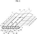
- the number of optical fibers is arbitrary in the present embodiment of the present invention and a concavity including slits may be formed at any intermediate between any pair of the optical fibers. Further the number of concavities is also arbitrary. Further the shape of the concavity may be formed in a shape having a roughly V-shaped cross section instead of the shape shown in FIG. 1 . As an example in such a structure, an embodiment shown in FIG. 3 is possible. In the embodiment shown in FIG. 3 , as each gap between adjacent optical fibers having a concavity is made as narrow as possible, the concavity is necessarily roughly V-shaped. Such an optical fiber ribbon 1 including a plurality of optical fibers 3 is made to branch into a plurality of ribbons 1A, 1B, 1C... each including a smaller number of optical fibers 3.
- the plurality of ribbons 1A, 1B, 1C... each including a smaller number of optical fibers 3 are readily respectively made to branch into ribbons each including a single optical fiber 3.
- a tool for shearing disclosed in Japanese Patent Application Laid-open No. 2006-030684 or a tool for realizing branching by means of a projection disclosed in 2006-030684 , may be used for instance.
- an optical fiber ribbon 1 containing eight optical fibers 3 shown in FIG. 1 has been produced, separated into optical fiber ribbons 1A, 1B each containing four of the optical fibers 3, and further respectively separated into optical fiber ribbons each including only one of the optical fibers 3, and then change of transmission loss is measured at each occasion of separation.
- a concavity 5A is formed at an intermediate between a #4 optical fiber and a #5 optical fiber, and slits 7 are formed to be arranged in series at regular intervals B along the concavity 5A.
- a single-mode optical fiber (SMF) regulated in JIS-C6835 or ITUT-G652 and an SR10 optical fiber in conformity to ITUT-G652B are applied to the optical fiber 3.
- An optical fiber of an SR10 equivalence is an optical fiber that has transmission of 0.50dB or less in regard to light of 1.550 ⁇ m in wavelength when the fiber is bent to make 10 turns with a bending diameter ⁇ of 20mm.
- the length A of the slit 7 is 72mm and the interval B is 8mm. More specifically, A+B is 80mm and A/(A+B) is 0.9. Given that a wire rod of 0.2mm in diameter is used as a tool, the following condition in which Y ⁇ A ⁇ 500 ⁇ mm , Y ⁇ A + B ⁇ 500 ⁇ mm , and 0.01 ⁇ A / A + B ⁇ 1 , is satisfied.
- Table 1 summarizes measurement results in which transmission loss change in a case where the optical fiber ribbon 1 is separated into two optical fiber ribbons 1A, 1B is measured. Table 1 shows two cases, one is related to a case where a wire rod of 0.2mm in diameter is used and another is related to a case where a tool by shearing is used.
- ⁇ Loss change at a time of separation is 1dB or larger (separation is possible).
- X separation is impossible.
- Table 2 summarizes measurement results in which transmission loss change in a case where the separated optical fiber ribbons 1A or 1B is further separated into optical fiber ribbons each including a single optical fiber is measured.
- Table 2 shows three cases, one is related to a case where a wire rod of 0.2mm in diameter is used, another is related to a case where a tool with a file is used, and the other is related to a case where a tool for realizing branching by means of a projection is used.
- the optical fiber ribbon 1 provides the following effects. More specifically, as it has a concavity including slits having a proper length A, bending of the optical fibers is suppressed when a tool for branching is inserted into any of the slits, thereby suppressing increase in transmission loss. By moving the tool along the concavity, the concavity splits and thus the optical fiber ribbon 1 easily becomes capable of branching.
- the blanket sheath 5 can be produced only from one layer of a resin. This leads to a possibility for production of a very thin optical fiber ribbon 1 can be produced.
- a very thin optical fiber ribbon 1 is not only space-saving but also does facilitate the work of branching.
- the optical fiber ribbon 1 has a structure or shape similar to that of a conventional multi-core optical fiber ribbon, it can be used compatibly with the conventional multi-core optical fiber ribbon, apart from differences in properties such as easiness of branching.
- optical fiber ribbon which is readily made to branch by means of versatile tools with suppressing transmission loss by bending and a method for making the optical fiber ribbon branch are provided.
Landscapes
- Physics & Mathematics (AREA)
- General Physics & Mathematics (AREA)
- Optics & Photonics (AREA)
- Light Guides In General And Applications Therefor (AREA)
- Mechanical Coupling Of Light Guides (AREA)
Claims (4)
- System, das umfasst:ein Werkzeug (13) mit einer Breite X, undein Lichtwellenleiterband (1), das durch das Werkzeug (13) verzweigt werden kann, wobei das Lichtwellenleiterband (1) umfasst:eine Vielzahl von Lichtwellenleitern (3), die parallel verlaufen, wobei jeder der Lichtwellenleiter (3) einen zulässigen Krümmungsradius R aufweist,eine Deckhülle (5), die die Vielzahl von Lichtwellenleitern (3) vollständig bedeckt,eine oder mehrere Konkavitäten (5A), die an der Deckhülle (5) an einem oder mehreren Zwischenräumen zwischen den Lichtwellenleitern (3) ausgebildet sind, undSchlitze (7), die in Reihe mit einem regelmäßigen Intervall B entlang der Konkavitäten (5A) angeordnet sind, wobei sich die Schlitze (7) durch die Deckhülle (5) erstrecken und ermöglichen, dass das Werkzeug eingesteckt wird und die Deckhülle (5) mittels einer Bewegung des Werkzeugs (13) entlang der Konkavitäten (5A) geteilt wird, wobei jeder der Schlitze (7) eine Länge A vor dem Einstecken des Werkzeugs (13) aufweist, die derart vorgesehen ist, dass durch das Werkzeug (13) beim Erweitern der Schlitze (7) verursachte Biegungen der Lichtwellenleiter (3) den zulässigen Krümmungsradius R nicht überschreiten,wobei jeder der Lichtwellenleiter (3) einen Außendurchmesser D aufweist, die Deckhülle (5) eine Dicke t1 von den entsprechenden Lichtwellenleitern (3) zu einer Oberfläche aufweist, jede der Konkavitäten (5A) eine Dicke t2 aufweist und die Länge A der Schlitze, der zulässige Krümmungsradius R und die Intervalle B erfüllen:


- System nach Anspruch 1, wobei der zulässige Krümmungsradius R der Lichtwellenleiter 30 mm beträgt.
- System nach Anspruch 1, wobei die Dicke t1 die Beziehung 0 < t1 <= 0,025 mm erfüllt.
- Verfahren zum Herstellen einer Lichtwellenleiterbandverzweigung,
wobei das Lichtwellenleiterband umfasst:eine Vielzahl von Lichtwellenleitern (3), die parallel verlaufen, wobei jeder der Lichtwellenleiter (3) einen zulässigen Krümmungsradius R aufweist,eine Deckhülle (5), die die Vielzahl von Lichtwellenleitern (3) vollständig bedeckt,eine oder mehrere Konkavitäten (5A), die an der Deckhülle (5) an einem oder mehreren Zwischenräumen zwischen den Lichtwellenleitern (3) ausgebildet sind, undSchlitze (7), die in Reihe mit einem regelmäßigen Intervall B entlang der Konkavitäten (5A) angeordnet sind, wobei sich die Schlitze (7) durch die Deckhülle (5) erstrecken,wobei das Verfahren die folgenden Schritte umfasst:Einstecken eines Werkzeugs mit einer Breite X in einen der Schlitze, undBewegen des Werkzeugs entlang der Konkavitäten (5A), um die Deckhülle zu teilen,wobei jeder der Schlitze (7) eine Länge A vor dem Einstecken eines Werkzeugs (13) aufweist, die derart vorgesehen ist, dass durch das Werkzeug (13) beim Erweitern der Schlitze (7) verursachte Biegungen der Lichtwellenleiter (3) den zulässigen Krümmungsradius R nicht überschreiten,
wobei jeder der Lichtwellenleiter (3) einen Außendurchmesser D aufweist, die Deckhülle (5) eine Dicke t1 von den entsprechenden Lichtwellenleitern (3) zu einer Oberfläche aufweist, jede der Konkavitäten (5A) eine Dicke t2 aufweist und die Länge A der Schlitze, der zulässige Krümmungsradius R und die Intervalle B erfüllen:


Applications Claiming Priority (2)
| Application Number | Priority Date | Filing Date | Title |
|---|---|---|---|
| JP2008001278A JP2009163045A (ja) | 2008-01-08 | 2008-01-08 | 光ファイバテープ心線およびその分割方法 |
| PCT/JP2008/073594 WO2009087911A1 (ja) | 2008-01-08 | 2008-12-25 | 分岐可能な光ファイバテープ心線およびその分岐の方法 |
Publications (3)
| Publication Number | Publication Date |
|---|---|
| EP2239608A1 EP2239608A1 (de) | 2010-10-13 |
| EP2239608A4 EP2239608A4 (de) | 2013-05-29 |
| EP2239608B1 true EP2239608B1 (de) | 2019-09-25 |
Family
ID=40853035
Family Applications (1)
| Application Number | Title | Priority Date | Filing Date |
|---|---|---|---|
| EP08869892.3A Active EP2239608B1 (de) | 2008-01-08 | 2008-12-25 | System eines werkzeuges und einer verzweigungsfähige glasfaserband und verwandtes verzweigungsverfahren |
Country Status (6)
| Country | Link |
|---|---|
| US (1) | US8412014B2 (de) |
| EP (1) | EP2239608B1 (de) |
| JP (1) | JP2009163045A (de) |
| CN (1) | CN101910901A (de) |
| BR (1) | BRPI0821971A2 (de) |
| WO (1) | WO2009087911A1 (de) |
Families Citing this family (32)
| Publication number | Priority date | Publication date | Assignee | Title |
|---|---|---|---|---|
| JP4748539B2 (ja) * | 2008-03-29 | 2011-08-17 | 古河電気工業株式会社 | パイプ間融着力の測定装置及びその測定方法 |
| JP5697011B2 (ja) * | 2010-02-16 | 2015-04-08 | 古河電気工業株式会社 | 光ファイバケーブル、及び光ファイバケーブルの形成方法 |
| JP5564026B2 (ja) * | 2011-10-18 | 2014-07-30 | 株式会社フジクラ | 光ファイバテープ心線及びその光ファイバテープ心線を収納した光ファイバケーブル |
| JP5615854B2 (ja) * | 2012-01-31 | 2014-10-29 | 日本電信電話株式会社 | 光ファイバテープ及び光ファイバケーブル |
| JP2013205501A (ja) * | 2012-03-27 | 2013-10-07 | Sumitomo Electric Ind Ltd | 光ファイバテープ心線、及び光ファイバテープ心線を備えた光ファイバケーブル |
| CN103376521B (zh) * | 2012-04-24 | 2015-06-03 | 上海裕荣光电科技股份有限公司 | 器件专用光纤带及其制作方法 |
| CA2871108C (en) | 2012-05-02 | 2019-09-17 | Afl Telecommunications Llc | Round and small diameter optical cables with a ribbon-like optical fiber structure |
| US20150185428A1 (en) * | 2012-08-09 | 2015-07-02 | Fujikura Ltd. | Binder fiber for optical fiber unit |
| JP2015108756A (ja) * | 2013-12-05 | 2015-06-11 | 住友電気工業株式会社 | 光ファイバユニット、光ファイバケーブルおよび光ファイバユニットの製造方法 |
| JP6132438B2 (ja) * | 2014-03-19 | 2017-05-24 | コマツNtc株式会社 | シングルワイヤ式のワイヤソーによる切断方法およびシングルワイヤ式のワイヤソー |
| US9389382B2 (en) | 2014-06-03 | 2016-07-12 | Corning Optical Communications LLC | Fiber optic ribbon cable and ribbon |
| JP6639773B2 (ja) * | 2014-09-17 | 2020-02-05 | 古河電気工業株式会社 | ルースチューブ型光ファイバユニット |
| JP2016075814A (ja) * | 2014-10-07 | 2016-05-12 | 住友電気工業株式会社 | 光ファイバケーブル |
| JP6592909B2 (ja) * | 2015-02-03 | 2019-10-23 | 住友電気工業株式会社 | 光ケーブル及びその製造方法 |
| CN104898220A (zh) * | 2015-05-06 | 2015-09-09 | 深圳市特发信息股份有限公司 | 一种多层光纤带 |
| CA2994387A1 (en) * | 2015-07-31 | 2017-02-09 | Corning Optical Communications LLC | Rollable optical fiber ribbon |
| WO2017095541A1 (en) * | 2015-11-30 | 2017-06-08 | Corning Optical Communications LLC | Flexible optical fiber ribbon with ribbon body flexibility recesses |
| JP6106253B1 (ja) * | 2015-12-04 | 2017-03-29 | 株式会社フジクラ | 光ファイバテープ、光ファイバテープの製造方法、及び間欠固定型光ファイバテープの連結部の形成に用いられる紫外線硬化樹脂組成物 |
| JP2017125931A (ja) * | 2016-01-13 | 2017-07-20 | 住友電気工業株式会社 | 間欠連結型光ファイバテープ心線、光ケーブルおよび間欠連結型光ファイバテープ心線の製造方法 |
| WO2017122518A1 (ja) * | 2016-01-13 | 2017-07-20 | 住友電気工業株式会社 | 間欠連結型光ファイバテープ心線、光ケーブルおよび間欠連結型光ファイバテープ心線の製造方法 |
| US10989888B2 (en) * | 2016-02-02 | 2021-04-27 | Ofs Fitel, Llc | Flexible ribbon structure and method for making |
| CN105666787B (zh) * | 2016-04-12 | 2018-03-09 | 深圳市特发信息股份有限公司 | 一种多层光纤带模具 |
| US20190369344A1 (en) * | 2016-12-01 | 2019-12-05 | Commscope Technologies Llc | Fiber ribbonizer |
| JP7020049B2 (ja) * | 2017-10-16 | 2022-02-16 | 住友電気工業株式会社 | ダイス、および、光ファイバテープ心線の製造方法 |
| US20190219783A1 (en) * | 2018-01-12 | 2019-07-18 | Ofs Fitel, Llc | Multi-fiber unit tube optical fiber microcable incorporating rollable optical fibers ribbons |
| CN113678044A (zh) * | 2019-04-12 | 2021-11-19 | 住友电气工业株式会社 | 光纤带芯线、模具及光纤带芯线的制造方法 |
| US11579387B2 (en) * | 2019-08-14 | 2023-02-14 | Sterlite Technologies Limited | Arrangement of optical fibre ribbon stack and an optical fibre ribbon thereof |
| JPWO2022054940A1 (de) * | 2020-09-14 | 2022-03-17 | ||
| WO2022075364A1 (ja) * | 2020-10-07 | 2022-04-14 | 住友電気工業株式会社 | 光ファイバテープ心線、ダイス、および光ファイバテープ心線の製造方法 |
| US11442238B2 (en) * | 2020-12-22 | 2022-09-13 | Prysmian S.P.A. | Optical-fiber ribbon with spaced optical-fiber units |
| US11780103B2 (en) | 2021-02-11 | 2023-10-10 | Prysmian S.P.A. | Fiber ribbon separation tool |
| JP2022183873A (ja) * | 2021-05-31 | 2022-12-13 | 住友電気工業株式会社 | 光ファイバリボン |
Citations (1)
| Publication number | Priority date | Publication date | Assignee | Title |
|---|---|---|---|---|
| JP2005165362A (ja) * | 2005-02-25 | 2005-06-23 | Furukawa Electric Co Ltd:The | 光ファイバテープ心線の分離方法及び分離工具セット |
Family Cites Families (17)
| Publication number | Priority date | Publication date | Assignee | Title |
|---|---|---|---|---|
| JPS5922404U (ja) | 1982-08-04 | 1984-02-10 | 日本電信電話株式会社 | 光フアイバユニツト |
| JP2573632B2 (ja) * | 1987-11-26 | 1997-01-22 | 住友電気工業株式会社 | テープ状光ファイバ心線の製造装置 |
| JPH0246411A (ja) | 1988-08-08 | 1990-02-15 | Sumitomo Electric Ind Ltd | テープ状光ファイバ心線の分岐方法 |
| JP2932509B2 (ja) * | 1989-07-13 | 1999-08-09 | 住友電気工業株式会社 | 光ファイバテープ心線の分割工具 |
| US4952020A (en) * | 1989-08-09 | 1990-08-28 | Amp Incorporated | Ribbon cable with optical fibers and electrical conductors |
| JPH07306320A (ja) * | 1994-05-11 | 1995-11-21 | Sumitomo Electric Ind Ltd | 光ファイバテープ心線の分離装置 |
| JP3645625B2 (ja) | 1995-09-13 | 2005-05-11 | オリンパス株式会社 | 顕微鏡自動焦点検出方法及び顕微鏡自動焦点検出装置及びそれを用いた顕微鏡 |
| JPH11183768A (ja) * | 1997-12-22 | 1999-07-09 | Yazaki Corp | 分割型光ファイバテープ心線及びその製造方法 |
| JP2003279756A (ja) * | 2002-03-26 | 2003-10-02 | Sumitomo Electric Ind Ltd | 光ファイバテープ心線の分岐方法 |
| KR100960185B1 (ko) * | 2002-05-28 | 2010-05-27 | 스미토모 덴키 고교 가부시키가이샤 | 광파이버 테이프 코어 |
| JP4055000B2 (ja) | 2003-08-11 | 2008-03-05 | 住友電気工業株式会社 | 光ファイバケーブル、光ファイバケーブルの製造方法及び光ファイバケーブルの製造装置 |
| JP2005249977A (ja) * | 2004-03-02 | 2005-09-15 | Sumitomo Electric Ind Ltd | 光ファイバケーブル |
| JP2005292518A (ja) * | 2004-03-31 | 2005-10-20 | Sumitomo Electric Ind Ltd | 光ファイバテープユニット及び光ファイバケーブル |
| US7039282B2 (en) * | 2004-06-30 | 2006-05-02 | Corning Cable Systems Llc | Optical fiber array with an intermittent profile and method for manufacturing the same |
| JP4115433B2 (ja) | 2004-07-16 | 2008-07-09 | 古河電気工業株式会社 | 光ファイバテープ心線分離方法及び分離工具 |
| JP2006267275A (ja) * | 2005-03-22 | 2006-10-05 | Fujikura Ltd | 光ファイバ心線分離工具 |
| JP2005352510A (ja) | 2005-07-29 | 2005-12-22 | Sumitomo Electric Ind Ltd | 光ファイバテープユニット及び光ファイバケーブル |
-
2008
- 2008-01-08 JP JP2008001278A patent/JP2009163045A/ja active Pending
- 2008-12-25 EP EP08869892.3A patent/EP2239608B1/de active Active
- 2008-12-25 WO PCT/JP2008/073594 patent/WO2009087911A1/ja not_active Ceased
- 2008-12-25 CN CN2008801243573A patent/CN101910901A/zh active Pending
- 2008-12-25 US US12/811,978 patent/US8412014B2/en active Active
- 2008-12-25 BR BRPI0821971-0A patent/BRPI0821971A2/pt not_active Application Discontinuation
Patent Citations (1)
| Publication number | Priority date | Publication date | Assignee | Title |
|---|---|---|---|---|
| JP2005165362A (ja) * | 2005-02-25 | 2005-06-23 | Furukawa Electric Co Ltd:The | 光ファイバテープ心線の分離方法及び分離工具セット |
Also Published As
| Publication number | Publication date |
|---|---|
| CN101910901A (zh) | 2010-12-08 |
| US20100296781A1 (en) | 2010-11-25 |
| EP2239608A1 (de) | 2010-10-13 |
| BRPI0821971A2 (pt) | 2015-06-23 |
| EP2239608A4 (de) | 2013-05-29 |
| JP2009163045A (ja) | 2009-07-23 |
| US8412014B2 (en) | 2013-04-02 |
| WO2009087911A1 (ja) | 2009-07-16 |
Similar Documents
| Publication | Publication Date | Title |
|---|---|---|
| EP2239608B1 (de) | System eines werkzeuges und einer verzweigungsfähige glasfaserband und verwandtes verzweigungsverfahren | |
| EP3330760B1 (de) | Glasfaserkabel | |
| CN108463758B (zh) | 间断性连结型光纤带芯线及光缆 | |
| US20040247265A1 (en) | Branching method for an optical fiber cable | |
| US12204141B2 (en) | Optical fiber bundle structure, optical connector, optical fiber connection structure, and method of manufacturing optical fiber bundle structure | |
| JP4974165B2 (ja) | 光ファイバの接続構造の製造方法 | |
| WO2010106858A1 (ja) | 光ファイバケーブル | |
| EP1391761A3 (de) | Polarisationserhaltender optischer Faserkoppler und sein Herstellungsverfahren | |
| KR102767788B1 (ko) | 광파이버 정렬 방법, 광파이버 융착 방법, 커넥터 딸린 광파이버 테이프의 제조 방법 및 간헐 연결형의 광파이버 테이프 | |
| EP4027180B1 (de) | Optisches faserband, optisches faserkabel und mit verbinder versehenes optisches faserkabel | |
| US12117662B2 (en) | Intermittent connection-type optical fiber tape core, optical fiber cable and connector-equipped optical fiber cord | |
| CA1104395A (en) | Splice for optical ribbon having elongated tensile strength elements in the ribbon and method of splicing the same | |
| EP4414762A1 (de) | Optisches faserband | |
| JP6365459B2 (ja) | 光ファイバテープ心線、光ファイバケーブルおよび光ファイバコード | |
| US20060002669A1 (en) | Optical fiber array with an intermittent profile and method for manufacturing the same | |
| US10859780B2 (en) | Optical fiber unit, optical fiber cable, and method for manufacturing optical fiber unit | |
| JP4665535B2 (ja) | 光ファイバケーブル | |
| HK1147806A (en) | Optical fiber tape core wire able to be branched and branching method thereof | |
| JP2009217194A (ja) | 光ファイバケーブル | |
| JP2003295013A (ja) | 単心分離型光ファイバテープ心線 | |
| CN106873102B (zh) | 一种光缆及光缆制作方法 | |
| KR200184180Y1 (ko) | 리본형 다심 광섬유를 가이드하는 단조장용 슬롯형 광케이블 | |
| JP2012053107A (ja) | 光ファイバケーブル | |
| JPH0229606A (ja) | テープ状光ファイバ心線の分岐用工具及びその使用方法 | |
| JP2005043719A (ja) | 光ファイバテープ心線 |
Legal Events
| Date | Code | Title | Description |
|---|---|---|---|
| PUAI | Public reference made under article 153(3) epc to a published international application that has entered the european phase |
Free format text: ORIGINAL CODE: 0009012 |
|
| 17P | Request for examination filed |
Effective date: 20100804 |
|
| AK | Designated contracting states |
Kind code of ref document: A1 Designated state(s): AT BE BG CH CY CZ DE DK EE ES FI FR GB GR HR HU IE IS IT LI LT LU LV MC MT NL NO PL PT RO SE SI SK TR |
|
| AX | Request for extension of the european patent |
Extension state: AL BA MK RS |
|
| DAX | Request for extension of the european patent (deleted) | ||
| A4 | Supplementary search report drawn up and despatched |
Effective date: 20130425 |
|
| RIC1 | Information provided on ipc code assigned before grant |
Ipc: G02B 6/44 20060101AFI20130419BHEP |
|
| STAA | Information on the status of an ep patent application or granted ep patent |
Free format text: STATUS: EXAMINATION IS IN PROGRESS |
|
| 17Q | First examination report despatched |
Effective date: 20180307 |
|
| GRAP | Despatch of communication of intention to grant a patent |
Free format text: ORIGINAL CODE: EPIDOSNIGR1 |
|
| STAA | Information on the status of an ep patent application or granted ep patent |
Free format text: STATUS: GRANT OF PATENT IS INTENDED |
|
| INTG | Intention to grant announced |
Effective date: 20190523 |
|
| RIN1 | Information on inventor provided before grant (corrected) |
Inventor name: SATO, YUKIKO Inventor name: OKADA, NAOKI Inventor name: SANO, KEIKO |
|
| GRAS | Grant fee paid |
Free format text: ORIGINAL CODE: EPIDOSNIGR3 |
|
| GRAA | (expected) grant |
Free format text: ORIGINAL CODE: 0009210 |
|
| STAA | Information on the status of an ep patent application or granted ep patent |
Free format text: STATUS: THE PATENT HAS BEEN GRANTED |
|
| AK | Designated contracting states |
Kind code of ref document: B1 Designated state(s): AT BE BG CH CY CZ DE DK EE ES FI FR GB GR HR HU IE IS IT LI LT LU LV MC MT NL NO PL PT RO SE SI SK TR |
|
| REG | Reference to a national code |
Ref country code: GB Ref legal event code: FG4D |
|
| REG | Reference to a national code |
Ref country code: CH Ref legal event code: EP |
|
| REG | Reference to a national code |
Ref country code: AT Ref legal event code: REF Ref document number: 1184370 Country of ref document: AT Kind code of ref document: T Effective date: 20191015 |
|
| REG | Reference to a national code |
Ref country code: IE Ref legal event code: FG4D |
|
| REG | Reference to a national code |
Ref country code: DE Ref legal event code: R096 Ref document number: 602008061295 Country of ref document: DE |
|
| REG | Reference to a national code |
Ref country code: SE Ref legal event code: TRGR |
|
| REG | Reference to a national code |
Ref country code: NL Ref legal event code: FP |
|
| PG25 | Lapsed in a contracting state [announced via postgrant information from national office to epo] |
Ref country code: BG Free format text: LAPSE BECAUSE OF FAILURE TO SUBMIT A TRANSLATION OF THE DESCRIPTION OR TO PAY THE FEE WITHIN THE PRESCRIBED TIME-LIMIT Effective date: 20191225 Ref country code: NO Free format text: LAPSE BECAUSE OF FAILURE TO SUBMIT A TRANSLATION OF THE DESCRIPTION OR TO PAY THE FEE WITHIN THE PRESCRIBED TIME-LIMIT Effective date: 20191225 Ref country code: LT Free format text: LAPSE BECAUSE OF FAILURE TO SUBMIT A TRANSLATION OF THE DESCRIPTION OR TO PAY THE FEE WITHIN THE PRESCRIBED TIME-LIMIT Effective date: 20190925 Ref country code: HR Free format text: LAPSE BECAUSE OF FAILURE TO SUBMIT A TRANSLATION OF THE DESCRIPTION OR TO PAY THE FEE WITHIN THE PRESCRIBED TIME-LIMIT Effective date: 20190925 |
|
| REG | Reference to a national code |
Ref country code: LT Ref legal event code: MG4D |
|
| PG25 | Lapsed in a contracting state [announced via postgrant information from national office to epo] |
Ref country code: LV Free format text: LAPSE BECAUSE OF FAILURE TO SUBMIT A TRANSLATION OF THE DESCRIPTION OR TO PAY THE FEE WITHIN THE PRESCRIBED TIME-LIMIT Effective date: 20190925 Ref country code: GR Free format text: LAPSE BECAUSE OF FAILURE TO SUBMIT A TRANSLATION OF THE DESCRIPTION OR TO PAY THE FEE WITHIN THE PRESCRIBED TIME-LIMIT Effective date: 20191226 |
|
| REG | Reference to a national code |
Ref country code: AT Ref legal event code: MK05 Ref document number: 1184370 Country of ref document: AT Kind code of ref document: T Effective date: 20190925 |
|
| PG25 | Lapsed in a contracting state [announced via postgrant information from national office to epo] |
Ref country code: ES Free format text: LAPSE BECAUSE OF FAILURE TO SUBMIT A TRANSLATION OF THE DESCRIPTION OR TO PAY THE FEE WITHIN THE PRESCRIBED TIME-LIMIT Effective date: 20190925 Ref country code: PT Free format text: LAPSE BECAUSE OF FAILURE TO SUBMIT A TRANSLATION OF THE DESCRIPTION OR TO PAY THE FEE WITHIN THE PRESCRIBED TIME-LIMIT Effective date: 20200127 Ref country code: AT Free format text: LAPSE BECAUSE OF FAILURE TO SUBMIT A TRANSLATION OF THE DESCRIPTION OR TO PAY THE FEE WITHIN THE PRESCRIBED TIME-LIMIT Effective date: 20190925 Ref country code: RO Free format text: LAPSE BECAUSE OF FAILURE TO SUBMIT A TRANSLATION OF THE DESCRIPTION OR TO PAY THE FEE WITHIN THE PRESCRIBED TIME-LIMIT Effective date: 20190925 Ref country code: EE Free format text: LAPSE BECAUSE OF FAILURE TO SUBMIT A TRANSLATION OF THE DESCRIPTION OR TO PAY THE FEE WITHIN THE PRESCRIBED TIME-LIMIT Effective date: 20190925 Ref country code: PL Free format text: LAPSE BECAUSE OF FAILURE TO SUBMIT A TRANSLATION OF THE DESCRIPTION OR TO PAY THE FEE WITHIN THE PRESCRIBED TIME-LIMIT Effective date: 20190925 |
|
| PG25 | Lapsed in a contracting state [announced via postgrant information from national office to epo] |
Ref country code: CZ Free format text: LAPSE BECAUSE OF FAILURE TO SUBMIT A TRANSLATION OF THE DESCRIPTION OR TO PAY THE FEE WITHIN THE PRESCRIBED TIME-LIMIT Effective date: 20190925 Ref country code: SK Free format text: LAPSE BECAUSE OF FAILURE TO SUBMIT A TRANSLATION OF THE DESCRIPTION OR TO PAY THE FEE WITHIN THE PRESCRIBED TIME-LIMIT Effective date: 20190925 Ref country code: IS Free format text: LAPSE BECAUSE OF FAILURE TO SUBMIT A TRANSLATION OF THE DESCRIPTION OR TO PAY THE FEE WITHIN THE PRESCRIBED TIME-LIMIT Effective date: 20200224 |
|
| REG | Reference to a national code |
Ref country code: DE Ref legal event code: R097 Ref document number: 602008061295 Country of ref document: DE |
|
| PG2D | Information on lapse in contracting state deleted |
Ref country code: IS |
|
| PG25 | Lapsed in a contracting state [announced via postgrant information from national office to epo] |
Ref country code: DK Free format text: LAPSE BECAUSE OF FAILURE TO SUBMIT A TRANSLATION OF THE DESCRIPTION OR TO PAY THE FEE WITHIN THE PRESCRIBED TIME-LIMIT Effective date: 20190925 Ref country code: IS Free format text: LAPSE BECAUSE OF FAILURE TO SUBMIT A TRANSLATION OF THE DESCRIPTION OR TO PAY THE FEE WITHIN THE PRESCRIBED TIME-LIMIT Effective date: 20200126 |
|
| PLBE | No opposition filed within time limit |
Free format text: ORIGINAL CODE: 0009261 |
|
| REG | Reference to a national code |
Ref country code: CH Ref legal event code: PL |
|
| STAA | Information on the status of an ep patent application or granted ep patent |
Free format text: STATUS: NO OPPOSITION FILED WITHIN TIME LIMIT |
|
| REG | Reference to a national code |
Ref country code: BE Ref legal event code: MM Effective date: 20191231 |
|
| PG25 | Lapsed in a contracting state [announced via postgrant information from national office to epo] |
Ref country code: MC Free format text: LAPSE BECAUSE OF FAILURE TO SUBMIT A TRANSLATION OF THE DESCRIPTION OR TO PAY THE FEE WITHIN THE PRESCRIBED TIME-LIMIT Effective date: 20190925 |
|
| 26N | No opposition filed |
Effective date: 20200626 |
|
| PG25 | Lapsed in a contracting state [announced via postgrant information from national office to epo] |
Ref country code: IE Free format text: LAPSE BECAUSE OF NON-PAYMENT OF DUE FEES Effective date: 20191225 Ref country code: LU Free format text: LAPSE BECAUSE OF NON-PAYMENT OF DUE FEES Effective date: 20191225 |
|
| PG25 | Lapsed in a contracting state [announced via postgrant information from national office to epo] |
Ref country code: SI Free format text: LAPSE BECAUSE OF FAILURE TO SUBMIT A TRANSLATION OF THE DESCRIPTION OR TO PAY THE FEE WITHIN THE PRESCRIBED TIME-LIMIT Effective date: 20190925 Ref country code: CH Free format text: LAPSE BECAUSE OF NON-PAYMENT OF DUE FEES Effective date: 20191231 Ref country code: LI Free format text: LAPSE BECAUSE OF NON-PAYMENT OF DUE FEES Effective date: 20191231 Ref country code: BE Free format text: LAPSE BECAUSE OF NON-PAYMENT OF DUE FEES Effective date: 20191231 |
|
| PG25 | Lapsed in a contracting state [announced via postgrant information from national office to epo] |
Ref country code: CY Free format text: LAPSE BECAUSE OF FAILURE TO SUBMIT A TRANSLATION OF THE DESCRIPTION OR TO PAY THE FEE WITHIN THE PRESCRIBED TIME-LIMIT Effective date: 20190925 |
|
| PG25 | Lapsed in a contracting state [announced via postgrant information from national office to epo] |
Ref country code: MT Free format text: LAPSE BECAUSE OF FAILURE TO SUBMIT A TRANSLATION OF THE DESCRIPTION OR TO PAY THE FEE WITHIN THE PRESCRIBED TIME-LIMIT Effective date: 20190925 Ref country code: HU Free format text: LAPSE BECAUSE OF FAILURE TO SUBMIT A TRANSLATION OF THE DESCRIPTION OR TO PAY THE FEE WITHIN THE PRESCRIBED TIME-LIMIT; INVALID AB INITIO Effective date: 20081225 |
|
| PG25 | Lapsed in a contracting state [announced via postgrant information from national office to epo] |
Ref country code: TR Free format text: LAPSE BECAUSE OF FAILURE TO SUBMIT A TRANSLATION OF THE DESCRIPTION OR TO PAY THE FEE WITHIN THE PRESCRIBED TIME-LIMIT Effective date: 20190925 |
|
| P01 | Opt-out of the competence of the unified patent court (upc) registered |
Effective date: 20230512 |
|
| PGFP | Annual fee paid to national office [announced via postgrant information from national office to epo] |
Ref country code: NL Payment date: 20251112 Year of fee payment: 18 |
|
| PGFP | Annual fee paid to national office [announced via postgrant information from national office to epo] |
Ref country code: DE Payment date: 20251028 Year of fee payment: 18 |
|
| PGFP | Annual fee paid to national office [announced via postgrant information from national office to epo] |
Ref country code: GB Payment date: 20251114 Year of fee payment: 18 |
|
| PGFP | Annual fee paid to national office [announced via postgrant information from national office to epo] |
Ref country code: IT Payment date: 20251121 Year of fee payment: 18 Ref country code: FI Payment date: 20251211 Year of fee payment: 18 |
|
| PGFP | Annual fee paid to national office [announced via postgrant information from national office to epo] |
Ref country code: FR Payment date: 20251110 Year of fee payment: 18 |
|
| PGFP | Annual fee paid to national office [announced via postgrant information from national office to epo] |
Ref country code: SE Payment date: 20251112 Year of fee payment: 18 |