EP3330760B1 - Glasfaserkabel - Google Patents
Glasfaserkabel Download PDFInfo
- Publication number
- EP3330760B1 EP3330760B1 EP16832810.2A EP16832810A EP3330760B1 EP 3330760 B1 EP3330760 B1 EP 3330760B1 EP 16832810 A EP16832810 A EP 16832810A EP 3330760 B1 EP3330760 B1 EP 3330760B1
- Authority
- EP
- European Patent Office
- Prior art keywords
- ribbon
- optical
- optical fiber
- fiber cable
- optical fibers
- Prior art date
- Legal status (The legal status is an assumption and is not a legal conclusion. Google has not performed a legal analysis and makes no representation as to the accuracy of the status listed.)
- Active
Links
Images


Classifications
-
- G—PHYSICS
- G02—OPTICS
- G02B—OPTICAL ELEMENTS, SYSTEMS OR APPARATUS
- G02B6/00—Light guides; Structural details of arrangements comprising light guides and other optical elements, e.g. couplings
- G02B6/44—Mechanical structures for providing tensile strength and external protection for fibres, e.g. optical transmission cables
- G02B6/4401—Optical cables
- G02B6/4403—Optical cables with ribbon structure
-
- G—PHYSICS
- G02—OPTICS
- G02B—OPTICAL ELEMENTS, SYSTEMS OR APPARATUS
- G02B6/00—Light guides; Structural details of arrangements comprising light guides and other optical elements, e.g. couplings
- G02B6/44—Mechanical structures for providing tensile strength and external protection for fibres, e.g. optical transmission cables
- G02B6/4401—Optical cables
- G02B6/4407—Optical cables with internal fluted support member
- G02B6/4408—Groove structures in support members to decrease or harmonise transmission losses in ribbon cables
-
- G—PHYSICS
- G02—OPTICS
- G02B—OPTICAL ELEMENTS, SYSTEMS OR APPARATUS
- G02B6/00—Light guides; Structural details of arrangements comprising light guides and other optical elements, e.g. couplings
- G02B6/44—Mechanical structures for providing tensile strength and external protection for fibres, e.g. optical transmission cables
- G02B6/4401—Optical cables
- G02B6/4407—Optical cables with internal fluted support member
- G02B6/4409—Optical cables with internal fluted support member for ribbons
-
- G—PHYSICS
- G02—OPTICS
- G02B—OPTICAL ELEMENTS, SYSTEMS OR APPARATUS
- G02B6/00—Light guides; Structural details of arrangements comprising light guides and other optical elements, e.g. couplings
- G02B6/44—Mechanical structures for providing tensile strength and external protection for fibres, e.g. optical transmission cables
- G02B6/4401—Optical cables
- G02B6/441—Optical cables built up from sub-bundles
-
- G—PHYSICS
- G02—OPTICS
- G02B—OPTICAL ELEMENTS, SYSTEMS OR APPARATUS
- G02B6/00—Light guides; Structural details of arrangements comprising light guides and other optical elements, e.g. couplings
- G02B6/44—Mechanical structures for providing tensile strength and external protection for fibres, e.g. optical transmission cables
- G02B6/4401—Optical cables
- G02B6/4429—Means specially adapted for strengthening or protecting the cables
- G02B6/443—Protective covering
- G02B6/4432—Protective covering with fibre reinforcements
-
- G—PHYSICS
- G02—OPTICS
- G02B—OPTICAL ELEMENTS, SYSTEMS OR APPARATUS
- G02B6/00—Light guides; Structural details of arrangements comprising light guides and other optical elements, e.g. couplings
- G02B6/44—Mechanical structures for providing tensile strength and external protection for fibres, e.g. optical transmission cables
- G02B6/4439—Auxiliary devices
- G02B6/4471—Terminating devices ; Cable clamps
- G02B6/4478—Bending relief means
-
- G—PHYSICS
- G02—OPTICS
- G02B—OPTICAL ELEMENTS, SYSTEMS OR APPARATUS
- G02B6/00—Light guides; Structural details of arrangements comprising light guides and other optical elements, e.g. couplings
- G02B6/44—Mechanical structures for providing tensile strength and external protection for fibres, e.g. optical transmission cables
- G02B6/4479—Manufacturing methods of optical cables
- G02B6/448—Ribbon cables
-
- G—PHYSICS
- G02—OPTICS
- G02B—OPTICAL ELEMENTS, SYSTEMS OR APPARATUS
- G02B6/00—Light guides; Structural details of arrangements comprising light guides and other optical elements, e.g. couplings
- G02B6/44—Mechanical structures for providing tensile strength and external protection for fibres, e.g. optical transmission cables
- G02B6/4479—Manufacturing methods of optical cables
- G02B6/449—Twisting
-
- H—ELECTRICITY
- H01—ELECTRIC ELEMENTS
- H01B—CABLES; CONDUCTORS; INSULATORS; SELECTION OF MATERIALS FOR THEIR CONDUCTIVE, INSULATING OR DIELECTRIC PROPERTIES
- H01B7/00—Insulated conductors or cables characterised by their form
- H01B7/08—Flat or ribbon cables
Definitions
- the present invention relates to an optical fiber cable, and more specifically, to an optical fiber cable having a slot rod with a plurality of grooves configured to accommodate therein a plurality of optical fiber ribbons.
- optical fiber cable having a slot rod also referred to as 'spacer'
- a slot rod also referred to as 'spacer'
- optical fiber ribbons (hereinafter, also referred to as 'ribbons') having a plurality of optical fibers arranged in parallel
- a tension member is embedded in a center of the slot rod
- an outer side of the slot rod is wrapped by a wrapping tape, which is then covered by a cable sheath (also referred to as 'sheath'), for example.
- JP 2014 211511 A discloses a technology of freely rotating the ribbons in the grooves.
- the two-part form of claim 1 relates to this document.
- US 6052502 A discloses a fiber optic cable having a slotted rod with grooves formed therein.
- the fiber optic cable has an ample tensile window, whereby macrobending and microbending of optical fibers in ribbon stacks is minimized.
- JP 3560687 B2 relates to an optical fiber cable used for an optical communication or the like.
- the optical fiber cable is a slot-type mold optical fiber cable and has a main tension member.
- JP 2014 074910 A relates to an optical fiber tape core wire.
- JP 5117519 B2 relates to an optical fiber cable accommodating an optical fiber tape core wire.
- EP 0 691 556 A1 relates to an optical fiber cable provided with a grooved spacer having on its outer circumference at least one SZ-spiral groove formed continuously along its longitudinal direction and at least one optical fiber tape accommodated in the groove of the grooved spacer.
- the tension member becomes a center of bending, tensile stress is generated at an outer side of the tension member, and compressive stress is generated at an inner side of the tension member, so that the compressive strain is applied to the ribbon positioned at the inner side.
- the ribbon can be moved in a longitudinal direction of the cable so as to cancel the compressive strain, the transmission loss is slight.
- the ribbons are mounted at high density in the grooves, the ribbons are difficult to move in the longitudinal direction of the cable and portions thereof that cannot withstand the compressive strain protrude outside the grooves, so that the macrobend loss may be caused at the portions. For this reason, it is needed to suppress the macrobend loss even when the ribbons are mounted at high density in the grooves of the slot rod.
- the present invention has been made in view of the above situations, and an object thereof is to provide an optical fiber cable capable of suppressing macrobend loss even when ribbons are mounted at high density in grooves.
- An optical fiber cable in accordance with an aspect of the present invention comprises the features recited in claim 1. Optional features are set forth in the dependent claims.
- the optical units stranded in advance are accommodated in the grooves of the slot rod, so that it is possible to suppress macrobend loss even when the ribbons are mounted at high density in the grooves.
- the compressive strain is dispersed without being concentrated on some optical fibers, so that it is possible to suppress the macrobend loss and to improve the bendability of the cable.
- the occupancy of the stranded optical units is 25% or higher, it is possible to increase the density of the ribbons. As a result, even when the ribbons are mounted at high density in the grooves, it is possible to suppress the transmission loss of the optical fibers.
- the ribbon is intermittently provided with coupling portions, at which the adjacent optical fibers are coupled therebetween, and non-coupling portions, at which the adjacent optical fibers are not coupled therebetween, in a longitudinal direction between some or all of the optical fibers in a state where the plurality of optical fibers is arranged in parallel.
- the non-coupling portions are provided intermittently in the longitudinal direction, so that it is possible to easily separate a single fiber.
- the transmission loss is favorable, and the intermittent ribbon is not separated upon primary stranding.
- the slit portions are provided intermittently along a longitudinal direction of the intermittent ribbons, it is possible to reduce a shock force that is to be applied to the optical fibers upon separation of a single fiber.
- the ribbon is continuously provided with the coupling portions in the longitudinal direction between the adjacent optical fibers of both ends thereof.
- the coupling portions formed continuously in the longitudinal direction between the adjacent optical fibers of both ends are provided, so that it is possible to improve the operability when setting the optical fibers to an optical fiber holder upon welding operation, without deteriorating the productivity and deformability easiness of the intermittent ribbon.
- a coupling length of the coupling portion positioned at a more inner side in an aligning direction of the ribbon is longer than a coupling length of the coupling portion positioned at an outermore side.
- the length of the coupling portion positioned at the inner side, to which the large deformation stress is to be applied, is made longer than the coupling portion positioned at the outer side, so that it is possible to prevent breakage.
- the ribbon is an optical fiber ribbon having 2N (N: an integer of 3 or greater) optical fibers, a sub-unit is integrated every M (M: an even number smaller than N) optical fibers, coupling portions and non-coupling portions are intermittently provided in a longitudinal direction between the adjacent sub-ribbons, the adjacent sub-ribbons are coupled and a ribbon part at which the 2M optical fibers are coupled is one part or less.
- the optical fiber ribbon can be easily bent in the width direction of the ribbon. As a result, it is possible to provide the optical fiber ribbon capable of preventing the deterioration of transmission characteristics and being easily handled, as compared to the related art. Also, when the optical fiber ribbon is configured by the sub-ribbons, a greater width than a single fiber is obtained. Therefore, when setting the ribbon to a welding holder, for example, the sub-ribbon has difficulty riding on the adjacent coupling portion, being inverted, and separating and protruding from a holder groove, so that it is possible to rapidly perform the welding operation.
- the ribbons to be accommodated in the same groove of the slot rod have at least two types of intermittent pitches.
- the coupling portions and the non-coupling portions are made not to repeat by constant lengths, even when the ribbon is mounted to the cable with a constant stranding pitch, the same structure portions of the intermittent ribbon are not mounted at the places of the cable at which the stranding pitch is same, and the stress to be applied to the intermittent ribbon is also alleviated in the longitudinal direction, so that it is possible to prevent the large transmission loss.
- Integrated ribbon parts in which the plurality of optical fibers is all coupled by the coupling portions and slitted ribbon parts in which the non-coupling portions adjacent to each other in an aligning direction of the ribbon are alternately arranged in a longitudinal direction of the ribbon are periodically provided in the longitudinal direction of the ribbon, and the slitted ribbon parts are configured to form single fiber ribbon parts, which are to be obtained by separating all the plurality of optical fibers with the non-coupling portions.
- the integrated ribbon part Upon the welding operation, the integrated ribbon part is used, and upon the separation operation, the single fiber ribbon part is used. Therefore, it is possible to achieve both the welding operability and the single fiber separability.
- a minimum thickness part of a rib configured to partition the respective grooves of the slot rod is positioned at an outermore side than a half circumferential portion of a diameter of a slot circumscribed circle of which a center is a tension member, and a rib thickness increases from the minimum thickness part toward a rib tip end.
- the rib of the slot rod is expanded at the tip end, so that a groove width at the periphery of the outer peripheral surface of the rib is narrowed.
- a height of the groove it is possible to resultantly increase the cross-sectional area of the groove. Therefore, it is possible to increase the cross-sectional area of the groove without changing the outer periphery position of the slot rod.
- a stranding pitch of the optical unit is shorter than a stranding pitch of the groove.
- the compressive strain is dispersed, so that it is possible to easily improve the bendability of the cable.
- the groove is configured by a combination of an SZ locus of a short period and an SZ locus of a period longer than the short period.
- the cable is wound to a body part of a winding drum (not shown) with relatively high tension so as to prevent wrapping breakage and the like, and the tension to be applied to the upper layer cable becomes a side pressure of the lower layer cable. Therefore, when the grooves are configured by a complex type of SZ on SZ, a period thereof becomes random (i.e., is not constant), so that it is possible to randomize the side pressure to be applied to the ribbon upon the winding to the drum, which also contributes to improvements on the side pressure characteristic.
- FIG. 1 depicts an example of an optical fiber cable in accordance with a first embodiment of the present invention.
- FIG. 2A is a sectional view depicting an example of the optical fiber cable.
- FIG. 2B is a sectional view depicting an example of the optical fiber cable using a modified example of a slot rib.
- FIGS. 3A to 3J depict an example and modified examples of a structure of an intermittent ribbon.
- An optical fiber cable 1 shown in FIGS. 1 and 2A is an SZ stranded ribbon slot-type cable, and includes optical units 17, a slot rod 20, a wrapping tape 30 longitudinally wrapped or helically wrapped around the slot rod 20, and a cable sheath 31 configured to cover an outer side of the wrapping tape 30.
- FIG. 1 is a pictorial view in which the optical fiber cable is branched on the way, the cable sheath 31 and the wrapping tape 30 shown in FIG. 2A are partially removed, and the slot rod 20 and the optical unit 17 hanging down from the slot rod 20 are shown.
- a stranding pitch P3 of slot grooves 22 is configured by a reversed part, an S-stranded part, a reversed part, a Z-stranded part and a reversed part.
- the slot rod 20 has a tension member 21 embedded in a central part thereof.
- a rod material having a bearing force against tensile and compression for example, a steel rod, FRP (Fiber Reinforced Plastics) or the like is used.
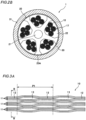
- an outer peripheral surface of the slot rod 20 is formed with a plurality of (for example, five) slot grooves 22 having an SZ shape along a longitudinal direction of the cable.
- the slot groove 22 corresponds to the groove of the present invention.
- the slot rod 20 has a slot rib 23 configured to partition the plurality of slot grooves 22 and radially extending from the tension member 21.
- the slot rib 23 corresponds to the rib of the present invention.
- FIG. 2B depicts a modified example of the slot rib of the slot rod 20.
- a slot rib 23A has a minimum thickness part, which is positioned at an outermore side than a half circumferential portion of a diameter of a slot circumscribed circle of which a center is the tension member 21, and a rib thickness increases from the minimum thickness part toward a rib tip end.
- a rib thickness increases from the minimum thickness part toward a rib tip end.
- the optical unit 17 is formed by stacking six intermittent ribbons 10 each of which having 12 fibers to configure 72 fibers, spirally stranding the same in one direction and bundling the same with a bundle material (not shown) for identification.
- the optical unit may be collected with being stranded into a periodically reversing SZ shape, for example, instead of the structure spirally stranded in one direction.
- the intermittent ribbon indicates a ribbon in which a plurality of optical fibers is aligned in line in parallel and the optical fibers adjacent to each other are intermittently coupled by coupling portions and non-coupling portions.
- FIG. 3A depicts a state where the intermittent ribbon is opened in the aligning direction
- FIG. 3B is a sectional view taken along a line B-B of FIG. 3A , as seen from an arrow direction.
- the shown intermittent ribbon 10 is a ribbon of 12 fibers of which fibers are intermittently connected every two fibers.
- a ribbon cover 14 of ultraviolet-curable resin or the like is provided around each optical fiber 11, and optical fibers each of which has two integrated fibers, for example, are intermittently coupled by coupling portions 12 and non-coupling portions 13.
- the adjacent ribbon covers 14 are coupled, and at the non-coupling portions 13, the adjacent ribbon covers 14 are separate from each other without being coupled.
- FIGS. 3C and 3D depict an intermittent ribbon 101 of a first modified example.
- FIG. 3C is a sectional view of the intermittent ribbon 101 in the aligning direction
- FIG. 3D is a perspective view of sub-units 11c, 11d.
- FIG. 3D when configuring one sub-unit 11a, 11b, 11c, 11d, 11e, 1 lf by two adjacent optical fibers 11, at least one of a recess portion and a step portion positioned between the adjacent sub-units is provided with a slit portion 14a.
- the slit portions 14a are intermittently provided along a longitudinal direction of the intermittent ribbon 101. Thereby, it is possible to reduce a shock force, which is to be applied to the optical fibers upon separation of a single fiber.
- the optical fiber to be accommodated in the intermittent ribbon is an optical fiber formed by further providing a colored cover on an outer side of an optical fiber in which a cover having about a cover outer diameter 250 ⁇ m is provided on a glass fiber having a standard outer diameter 125 ⁇ m, and the number of optical fibers to be accommodated is arbitrary.
- the intermittent ribbon may not be configured so that the coupling portions and the non-coupling portions are provided every two fibers.
- the intermittent ribbon may be intermittently coupled by the coupling portions and the non-coupling portions every one fiber.
- FIG. 3E depicts an intermittent ribbon 102 of a second modified example.
- the intermittent ribbon may be configured so that the coupling portions are continuously provided in the longitudinal direction between the adjacent optical fibers of both ends and the other optical fibers are intermittently coupled by the coupling portions and the non-coupling portions every one fiber.
- the coupling portions are continuously provided in the longitudinal direction between the adjacent optical fibers of both ends and the other optical fibers are intermittently coupled by the coupling portions and the non-coupling portions every one fiber.
- FIG. 3F depicts an intermittent ribbon 103 of a third modified example. Meanwhile, FIG. 3F depicts the intermittent ribbon closed in the aligning direction.
- the intermittent ribbon may be configured so that all coupling lengths of the coupling portions 12 are not necessarily required to be the same.
- coupling lengths d1, d1' of the coupling portions 12 positioned at a more inner side in the aligning direction of the optical fibers 11 may be longer than coupling lengths d2, d2' of the coupling portions 12 positioned at an outermore side. Thereby, the breakage of the coupling portions 12 positioned at the more inner side is suppressed, so that it is possible to maintain a shape of the ribbon and to easily handle the same.
- FIG 3G depicts an intermittent ribbon 104 of a fourth modified example. Meanwhile, FIG. 3G depicts the intermittent ribbon closed in the aligning direction.
- the coupling portions and the non-coupling portions are intermittently provided in the longitudinal direction between the adjacent sub-ribbons 15, and when a section of the intermittent ribbon 104 is seen from the aligning direction, the adjacent sub-ribbons are coupled and a ribbon part at which the 2M optical fibers 11 are coupled is one part or less.
- the intermittent ribbon when a section of the intermittent ribbon is seen from the aligning direction, the intermittent ribbon is configured by a combination of one 4-fiber ribbon part (consisting of two sets of the adjacent sub-ribbons 15) coupled with the coupling portions 12 and four 2-fiber ribbon parts (each of which consists of one set of the sub-ribbon 15) separated with the non-coupling portions 13 aligned in the ribbon aligning direction.
- the 4-fiber ribbon parts 16a to 16e are respectively provided at positions deviating in the longitudinal direction of the ribbon, it is possible to easily bend the intermittent ribbon in the ribbon aligning direction.
- the optical fiber ribbon that can prevent deterioration of transmission characteristics and can be easily handled.
- the optical fiber ribbon is configured by the sub-ribbons, a greater width than a single fiber is obtained. Therefore, when setting the intermittent ribbon to a welding holder, for example, the sub-ribbon has difficulty riding on the adjacent coupling portion, being inverted, and separating and protruding from a holder groove, so that it is possible to rapidly perform the welding operation.
- FIGS. 3H and 3I depict intermittent ribbons 105, 105' of a fifth modified example.
- FIGS. 3H and 3I depict the intermittent ribbon closed in the aligning direction.
- the intermittent ribbons to be accommodated in the same groove 22 of the slot rod 20 preferably have at least two types of intermittent pitches.
- an intermittent pitch (a length of the non-coupling portion 13+a length of the coupling portion 12) is different between adjacent pitches (A+B and C+D).
- respective intermittent pitches A+B, C+D, E+F, G+H are different and random.
- the non-coupling portions 13 and the coupling portions 12 of the intermittent ribbon are made not to repeat by constant lengths. Therefore, even when the intermittent ribbon is mounted to a cable with a constant stranding pitch, the same structure portions of the intermittent ribbon are not mounted at places of the cable at which the stranding pitch is same, and the stress to be applied to the intermittent ribbon is also alleviated in the longitudinal direction, so that it is possible to prevent the large transmission loss. Also, since the longitudinal random nature as the ribbon increases, the above configuration favorably acts, from a standpoint of PMD characteristics, too.
- FIG. 3J depicts an intermittent ribbon 106 of a sixth modified example. Meanwhile, FIG. 3J depicts the intermittent ribbon closed in the aligning direction.
- integrated ribbon parts 106a in which a plurality of (twelve) optical fibers is all coupled by the coupling portions 12 and slitted ribbon parts 106b in which the non-coupling portions 13 adjacent to each other in the aligning direction of the intermittent ribbon 106 are alternately arranged in the longitudinal direction of the intermittent ribbon 106 are periodically provided in the longitudinal direction of the intermittent ribbon 106.
- the slitted ribbon part 106b is not provided with the coupling portions 12, and is provided with single fiber ribbon parts 106c by the plurality of (twelve) optical fibers 11 separated by the non-coupling portions 13, as seen from the aligning direction of the intermittent ribbon 106. In this way, when the single fiber ribbon parts 106c are provided, it is possible to improve the single fiber separability.
- the slot rod 20 is wrapped and is collected into a round shape with the wrapping tape 30 so that the optical units 17 do not protrude, for example.
- a non-woven fabric formed to have a tape shape a tape formed by bonding a base material such as polyethylene terephthalate (PET) and a non-woven fabric each other, or the like is used.
- a water absorbing agent for example, absorbing powders
- the wrapping tape is made to function as a water absorbing layer, it is possible to provide the intermittent ribbon or the like with a waterproof property.
- An outer side of the wrapping tape 30 is covered with the cable sheath 31 made of PE (polyethylene), PVC (polyvinyl chloride) or the like, for example, and is formed to have a round shape.
- PE polyethylene
- PVC polyvinyl chloride
- FIG. 4 illustrates a state where the optical fiber cable is bent into a circular arc shape.
- the tension member becomes a center of bending, the tensile stress is generated at an outer side of the tension member, and the compressive stress shown with an arrow in FIG. 4 is generated at an inner side, so that the compressive strain is applied to the ribbon positioned at the inner side.
- the ribbon can be moved in the longitudinal direction of the cable so as to cancel the compressive strain, the transmission loss is slight.
- the ribbons are mounted at high density in the slot grooves, the ribbons are difficult to move in the longitudinal direction of the cable, and portions incapable of enduring the compressive strain protrude outside the slot grooves, so that the macrobend loss may be caused at the portions.
- the optical units 17 spirally stranded in advance in one direction are accommodated in the slot grooves 22. Thereby, even when the ribbons are mounted at high density in the slot grooves, the macrobend loss is suppressed.
- an occupancy i.e., a total cross-sectional area of ribbons/a cross-sectional area of slot groove
- an occupancy i.e., a total cross-sectional area of ribbons/a cross-sectional area of slot groove
- the total cross-sectional area of ribbons includes cross-sectional areas of the ribbon covers 14 and the ribbons 10 shown in FIGS. 3A and 3B .
- the cross-sectional area also increases.
- a stranding pitch P2 of the optical unit 17 was set to 500mm
- a stranding pitch P3 of the slot groove 22 was set to 700mm
- the occupancy was set to 50%
- the optical fiber cable 1 was bent into a circular arc shape of ⁇ 500mm, and the transmission loss was measured.
- the transmission loss (wavelength 1550nm) was 1dB/km or greater.
- the optical fiber cable 1 of the embodiment (the stranded optical units 17 were accommodated in the slot grooves 22) was bent into a circular arc shape, the transmission loss was 0.1dB/km or less.
- the optical units are stranded and collected, it is possible to implement the above occupancy even though the general ribbons are used.
- the intermittent ribbons are used, the flexibility is improved, so that it is possible to more easily increase the density of the ribbons.
- the compressive strain can be more easily dispersed, as compared to a configuration the stranding pitch P2 is made equal to or longer than the stranding pitch P3 of the slot grooves, so that it is possible to more easily improve the bendability of the cable.
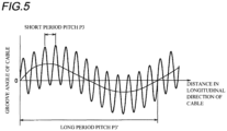
- FIG. 5 is a view for illustrating a slot rod in accordance with another embodiment.
- the slot grooves are configured with one type of stranding pitch.
- the slot grooves may also be configured by a combination of an SZ locus consisting of a sinusoidal curve of a short period and an SZ locus consisting of a sinusoidal curve of a period longer than the short period (a complex SZ type; also referred to as an SZ on SZ).
- a short period pitch P3 is set to 700mm, and a long period P3' is set to about 9100mm.
- the cable is wound to a body part of a winding drum (not shown) with relatively high tension so as to prevent wrapping breakage and the like, and the tension to be applied to the upper layer cable becomes a side pressure of the lower layer cable. Therefore, when the slot grooves are configured by a complex SZ type, a period thereof becomes random (is not constant), so that it is possible to randomize the side pressure to be applied to the intermittent ribbon upon the winding to the drum, which also contributes to improvements on the side pressure characteristic.
- the optical units 17 having the primarily stranded ribbons 10 were mounted to the optical fiber cable 1 of the embodiment.
- the intermittent ribbon pitch P1 of the ribbon 10 the primary stranding pitch P2 of the optical unit 17, the slot stranding pitch P3 of the slot groove 22 were respectively changed, and in each case, the transmission loss of the optical fiber cable 1 was evaluated and it was also evaluated whether the intermittent ribbon was separated upon the primary stranding.
- the results are shown in Table 1.
- the intermittent ribbon the ribbon shown in FIG. 3A was used as the intermittent ribbon. [Table 1] No.
- intermittent ribbon pitch P1 primary stranding pitch P2 slot stranding pitch P3 P2/P 1 composite stranding pitch (1/Pmix 1/(P2+P3) ) transmission loss (dB/km) whether intermittent ribbon was separated 1 50 250 600 5.0 176 ⁇ (0.19) ⁇ 2 100 250 600 2.5 176 ⁇ (0.19) ⁇ 3 150 250 600 1.7 176 ⁇ (0.19) ⁇ 4 200 250 600 1.3 176 ⁇ (0.19) ⁇ (separated) 5 50 500 600 10.0 273 ⁇ (0.35) ⁇ 6 100 500 600 5.0 273 ⁇ (0.19) ⁇ 7 150 500 600 3.3 273 ⁇ (0.19) ⁇ 8 200 500 600 2.5 273 ⁇ (0.19) ⁇ 9 50 750 600 15.0 333 ⁇ (0.40) ⁇ 10 100 750 600 7.5 333 ⁇ (0.24) ⁇ 11 150 750 600 5.0 333 ⁇ (0.23) ⁇ 12 200 750 600 3.8 333 ⁇ (0.21) ⁇ 13 50 1000 600 20.0 375 ⁇ (0
- a relation of the intermittent ribbon pitch P1, the primary stranding pitch P2 and the slot stranding pitch P3 was 2.5 ⁇ P2/P1 ⁇ 7 .5
Landscapes
- Physics & Mathematics (AREA)
- General Physics & Mathematics (AREA)
- Optics & Photonics (AREA)
- Engineering & Computer Science (AREA)
- Manufacturing & Machinery (AREA)
- Light Guides In General And Applications Therefor (AREA)
- Communication Cables (AREA)
Claims (10)
- Glasfaserkabel (1), umfassend:optische Einheiten (17), in denen jeweils Bänder (10), die jeweils eine Vielzahl von parallel angeordneten Glasfasern (11) aufweisen, gesammelt werden;eine Schlitzstange (20), die eine Vielzahl von Nuten (22) aufweist, die jeweils so ausgebildet sind, dass sie die optischen Einheiten (17) darin aufnehmen können;ein Spannelement (21), auf das Spannung ausgeübt werden soll; undeinen Kabelmantel (31), der so ausgebildet ist, dass er eine Außenseite der Schlitzstange (20) bedeckt,wobei in jeder der Nuten (22) eine Belegung der optischen Einheiten (17), berechnet aus einer Querschnittsfläche der optischen Einheiten (17) relativ zu einer Querschnittsfläche der Nut (22), 25 % bis 65 % beträgt,wobeiin jeder der Nuten (22) die optischen Einheiten (17) in einem Zustand untergebracht sind, in dem jede der optischen Einheiten (17) verseilt ist,das Band (10) in einer Längsrichtung zwischen einigen oder allen der Glasfasern (11) in einem Zustand, in dem die Vielzahl der Glasfasern (11) parallel angeordnet ist, intermittierend mit Kopplungsabschnitten (12), an denen die benachbarten Glasfasern (11) dazwischen gekoppelt sind, und Nicht-Kopplungsabschnitten (13), an denen die benachbarten Glasfasern (11) nicht dazwischen gekoppelt sind, bereitgestellt ist, dadurch gekennzeichnet ist, dasswenn eine intermittierende Teilung des Bandes (10) in der Längsrichtung als P1 bezeichnet ist, eine Verseilungsteilung der optischen Einheit (17) als P2 bezeichnet ist und eine Verseilungsteilung der Schlitzstange (20) als P3 bezeichnet ist, eine Beziehung von 2,5 ≤ P2/P1 ≤ 7,5 erfüllt ist und eine zusammengesetzte Verseilungsteilung Pmix, ausgedrückt durch 1/Pmix = 1/P2 + 1/P3, 398 mm oder kleiner ist.
- Glasfaserkabel (1) nach Anspruch 1, wobei, wenn die zwei benachbarten Glasfasern (11) des Bandes (10) als eine Untereinheit ausgebildet sind, mindestens einer von einem Ausnehmungsabschnitt und einem Stufenabschnitt, der zwischen den benachbarten Untereinheiten positioniert ist, intermittierend mit einem Schlitzabschnitt in einer Längsrichtung bereitgestellt ist.
- Glasfaserkabel (1) nach Anspruch 1 oder 2, wobei das Band (10) in der Längsrichtung zwischen den benachbarten Glasfasern (11) an seinen beiden Enden durchgehend mit den Kopplungsabschnitten (12) bereitgestellt ist.
- Glasfaserkabel (1) nach Anspruch 1, 2 oder 3, wobei eine Kopplungslänge eines Kopplungsabschnitts (12), der an einer weiter innen liegenden Seite in einer Ausrichtungsrichtung des Bandes (10) positioniert ist, länger ist als eine Kopplungslänge eines Kopplungsabschnitts (12), der an einer weiter außen liegenden Seite positioniert ist.
- Glasfaserkabel (1) nach Anspruch 1, wobei das Band (10) ein Glasfaserband ist, das 2N (N: eine ganze Zahl von 3 oder mehr) Glasfasern (11) aufweist, eine Untereinheit alle M (M: eine gerade Zahl kleiner als N) Glasfasern (11) integriert ist, Kupplungsabschnitte (12) und Nicht-Kupplungsabschnitte (13) intermittierend in einer Längsrichtung zwischen den benachbarten Teilbändern bereitgestellt sind, die benachbarten Teilbänder gekoppelt sind und ein Bandteil, an dem die 2M Glasfasern gekoppelt sind, ein Teil oder weniger ist.
- Glasfaserkabel (1) nach einem der Ansprüche 1 bis 5, wobei Bänder (10), die in der gleichen Nut (22) der Schlitzstange (20) untergebracht werden sollen, mindestens zwei Arten von intermittierenden Teilungen aufweisen.
- Glasfaserkabel (1) nach Anspruch 1 oder 2, wobei integrierte Bandteile, bei denen die Vielzahl von Glasfasern (11) sämtlich durch die Kopplungsabschnitte (12) gekoppelt ist, und geschlitzte Bandteile, bei denen die in einer Ausrichtungsrichtung des Bandes einander benachbarten Nicht-Kopplungsabschnitte (13) abwechselnd in einer Längsrichtung des Bandes (10) angeordnet sind, periodisch in der Längsrichtung des Bandes (10) bereitgestellt sind, und die geschlitzten Bandteile so ausgebildet sind, dass sie Einzelfaser-Bandteile bilden, die durch Trennen aller der Vielzahl von Glasfasern (11) mit den Nicht-Kopplungsabschnitten (13) zu erhalten sind.
- Glasfaserkabel (1) nach einem der Ansprüche 1 bis 7, wobei die Schlitzstange (20) das Spannelement (21) in einem zentralen Teil davon eingebettet aufweist; ein Teil mit minimaler Dicke einer Rippe (23 A), die so ausgebildet ist, dass sie zwei entsprechende Nuten (22) der Schlitzstange (20) unterteilt, radial außerhalb eines Kreises positioniert ist, der den halben Durchmesser der Schlitzstange (20) aufweist, wobei der Mittelpunkt des Kreises das Spannelement (21) ist; und eine Rippendicke vom Teil mit der geringsten Dicke in Richtung eines Rippenspitzenendes zunimmt.
- Glasfaserkabel nach einem der Ansprüche 1 bis 8, wobei eine Verseilungsteilung der optischen Einheit kürzer ist als eine Verseilungsteilung der Nut.
- Glasfaserkabel (1) nach einem der Ansprüche 1 bis 9, wobei die Nut (22) durch eine Kombination aus einer SZ-Stelle mit kurzer Periode und einer SZ-Stelle mit einer längeren Periode als der kurzen Periode ausgebildet ist.
Applications Claiming Priority (4)
| Application Number | Priority Date | Filing Date | Title |
|---|---|---|---|
| JP2015151941A JP6459833B2 (ja) | 2015-07-31 | 2015-07-31 | 光ファイバケーブル |
| JP2015156064A JP6365459B2 (ja) | 2015-08-06 | 2015-08-06 | 光ファイバテープ心線、光ファイバケーブルおよび光ファイバコード |
| JP2015202539A JP6679875B2 (ja) | 2015-10-14 | 2015-10-14 | 光ファイバケーブル用のスロットロッドおよび光ファイバケーブル |
| PCT/JP2016/071628 WO2017022531A1 (ja) | 2015-07-31 | 2016-07-22 | 光ファイバケーブル |
Publications (3)
| Publication Number | Publication Date |
|---|---|
| EP3330760A1 EP3330760A1 (de) | 2018-06-06 |
| EP3330760A4 EP3330760A4 (de) | 2019-03-27 |
| EP3330760B1 true EP3330760B1 (de) | 2024-10-30 |
Family
ID=57942955
Family Applications (1)
| Application Number | Title | Priority Date | Filing Date |
|---|---|---|---|
| EP16832810.2A Active EP3330760B1 (de) | 2015-07-31 | 2016-07-22 | Glasfaserkabel |
Country Status (4)
| Country | Link |
|---|---|
| US (1) | US10514517B2 (de) |
| EP (1) | EP3330760B1 (de) |
| TW (1) | TWI732776B (de) |
| WO (1) | WO2017022531A1 (de) |
Families Citing this family (20)
| Publication number | Priority date | Publication date | Assignee | Title |
|---|---|---|---|---|
| AU2017224629A1 (en) * | 2016-02-23 | 2018-07-12 | Sumitomo Electric Industries, Ltd. | Intermittent connection type optical fiber ribbon, manufacturing method for intermittent connection type optical fiber ribbon, optical fiber cable and optical fiber cord |
| CN110770621A (zh) * | 2017-06-14 | 2020-02-07 | 住友电气工业株式会社 | 槽型光缆 |
| JPWO2019059251A1 (ja) * | 2017-09-21 | 2020-10-15 | 住友電気工業株式会社 | 光ファイバケーブル |
| US10983294B2 (en) * | 2018-02-27 | 2021-04-20 | Optical Cable Corporation | Deployable fiber optic cable with partially bonded ribbon fibers |
| US11579387B2 (en) * | 2019-08-14 | 2023-02-14 | Sterlite Technologies Limited | Arrangement of optical fibre ribbon stack and an optical fibre ribbon thereof |
| WO2021045201A1 (ja) | 2019-09-05 | 2021-03-11 | 住友電気工業株式会社 | 光ファイバテープ心線、光ファイバケーブルおよびコネクタ付光ファイバコード |
| CN114730060B (zh) * | 2019-11-27 | 2023-10-31 | 株式会社藤仓 | 光纤电缆的芯部露出方法以及光纤电缆 |
| US11693201B2 (en) * | 2020-02-27 | 2023-07-04 | Sterlite Technologies Limited | Intermittently bonded optical fibre ribbon with unequal bond and gap lengths |
| CN115244443B (zh) * | 2020-03-09 | 2025-03-21 | 住友电气工业株式会社 | 光纤带和光纤缆线 |
| WO2021217079A1 (en) | 2020-04-24 | 2021-10-28 | Commscope Technologies Llc | Fiber routing systems and methods |
| JP7422230B2 (ja) * | 2020-07-01 | 2024-01-25 | 株式会社フジクラ | 光ファイバユニット及び光ファイバユニット製造方法 |
| JP7084449B2 (ja) * | 2020-07-10 | 2022-06-14 | 古河電気工業株式会社 | 光ファイバテープ心線、光ファイバケーブル |
| WO2022059654A1 (ja) * | 2020-09-16 | 2022-03-24 | 住友電気工業株式会社 | 光ファイバテープ心線およびサブテープ型光ファイバテープ心線 |
| EP4372441A4 (de) * | 2021-07-13 | 2025-06-18 | Fujikura Ltd. | Optisches faserband |
| CN113625405B (zh) * | 2021-08-30 | 2023-03-03 | 长飞光电线缆(苏州)有限公司 | 一种光纤带光缆 |
| EP4455751A4 (de) * | 2021-12-24 | 2025-05-07 | Sumitomo Electric Industries, Ltd. | Optisches kabel und verfahren zur herstellung eines optischen kabels |
| EP4459342A4 (de) * | 2021-12-27 | 2025-12-31 | Fujikura Ltd | Glasfaseranordnung und optisches kabel |
| CN114911016B (zh) * | 2022-05-09 | 2024-02-02 | 杭州富通通信技术股份有限公司 | 抗风力光缆 |
| CN114924374B (zh) * | 2022-06-29 | 2023-05-09 | 富通集团有限公司 | 带状光缆 |
| CN115113352B (zh) * | 2022-07-27 | 2023-04-28 | 富通集团有限公司 | 带状光缆 |
Citations (1)
| Publication number | Priority date | Publication date | Assignee | Title |
|---|---|---|---|---|
| EP0691556A1 (de) * | 1994-07-06 | 1996-01-10 | The Furukawa Electric Co., Ltd. | Optisches Kabel |
Family Cites Families (22)
| Publication number | Priority date | Publication date | Assignee | Title |
|---|---|---|---|---|
| JPS5320578A (en) | 1976-08-11 | 1978-02-24 | Hitachi Ltd | Multi-core cable |
| JPH01163710A (ja) * | 1987-02-25 | 1989-06-28 | Sumitomo Electric Ind Ltd | 光ケ−ブル |
| JP3560687B2 (ja) | 1995-06-08 | 2004-09-02 | 昭和電線電纜株式会社 | 光ファイバケーブル |
| JPH09197204A (ja) * | 1996-01-12 | 1997-07-31 | Mitsubishi Cable Ind Ltd | 光ファイバケーブル |
| US6052502A (en) * | 1997-09-22 | 2000-04-18 | Siecor Corporation | Ribbon optical cable having improved strength |
| JPH11202170A (ja) * | 1998-01-16 | 1999-07-30 | Sumitomo Electric Ind Ltd | 光ファイバケーブル |
| GB2343014A (en) | 1998-10-23 | 2000-04-26 | Bowthorpe Plc | Optic fibre cable |
| US6212321B1 (en) * | 1999-03-25 | 2001-04-03 | Sumitomo Electric Industries, Ltd. | Optical cable |
| JP4670523B2 (ja) * | 2005-07-19 | 2011-04-13 | 住友電気工業株式会社 | 光ケーブル |
| JP4143651B2 (ja) | 2006-04-04 | 2008-09-03 | 株式会社フジクラ | 光ファイバテープ心線及び前記光ファイバテープ心線を収納した光ファイバケーブル |
| WO2010001663A1 (ja) * | 2008-06-30 | 2010-01-07 | 日本電信電話株式会社 | 光ファイバケーブル及び光ファイバテープ |
| JP5117519B2 (ja) | 2010-02-16 | 2013-01-16 | 古河電気工業株式会社 | 光ファイバテープ心線及び光ファイバケーブル |
| JP5697011B2 (ja) | 2010-02-16 | 2015-04-08 | 古河電気工業株式会社 | 光ファイバケーブル、及び光ファイバケーブルの形成方法 |
| JP5866786B2 (ja) * | 2011-03-30 | 2016-02-17 | 住友電気工業株式会社 | 光ファイバテープ心線 |
| JP6064347B2 (ja) | 2012-03-22 | 2017-01-25 | カシオ計算機株式会社 | 情報処理装置及びプログラム |
| JP2014074910A (ja) * | 2012-10-03 | 2014-04-24 | Sumitomo Electric Ind Ltd | 光ファイバテープ心線 |
| TW201430432A (zh) | 2013-01-31 | 2014-08-01 | Ube Exsymo Co Ltd | 光纖隔片、其製造方法及光纖電纜 |
| JP2014211511A (ja) * | 2013-04-18 | 2014-11-13 | 住友電気工業株式会社 | 光ケーブル |
| JP6191343B2 (ja) | 2013-09-06 | 2017-09-06 | 住友電気工業株式会社 | 光ケーブル |
| JP2016020990A (ja) | 2014-07-15 | 2016-02-04 | 住友電気工業株式会社 | 光ケーブル用のスロットロッド及び光ケーブル |
| JP2016075814A (ja) * | 2014-10-07 | 2016-05-12 | 住友電気工業株式会社 | 光ファイバケーブル |
| JP6373196B2 (ja) * | 2015-01-19 | 2018-08-15 | 古河電気工業株式会社 | 光ファイバケーブル |
-
2016
- 2016-07-22 WO PCT/JP2016/071628 patent/WO2017022531A1/ja not_active Ceased
- 2016-07-22 US US15/748,810 patent/US10514517B2/en active Active
- 2016-07-22 EP EP16832810.2A patent/EP3330760B1/de active Active
- 2016-07-29 TW TW105124222A patent/TWI732776B/zh active
Patent Citations (1)
| Publication number | Priority date | Publication date | Assignee | Title |
|---|---|---|---|---|
| EP0691556A1 (de) * | 1994-07-06 | 1996-01-10 | The Furukawa Electric Co., Ltd. | Optisches Kabel |
Also Published As
| Publication number | Publication date |
|---|---|
| HK1254082A1 (en) | 2019-07-12 |
| TWI732776B (zh) | 2021-07-11 |
| US10514517B2 (en) | 2019-12-24 |
| WO2017022531A1 (ja) | 2017-02-09 |
| EP3330760A1 (de) | 2018-06-06 |
| TW201728930A (zh) | 2017-08-16 |
| EP3330760A4 (de) | 2019-03-27 |
| US20190011656A1 (en) | 2019-01-10 |
Similar Documents
| Publication | Publication Date | Title |
|---|---|---|
| EP3330760B1 (de) | Glasfaserkabel | |
| CN109642999B (zh) | 光纤缆线 | |
| EP3115816B1 (de) | Optisches kabel | |
| US9989723B2 (en) | Loose tube-type optical fiber unit | |
| US10101549B2 (en) | Optical fiber cable | |
| KR20080027328A (ko) | 광섬유 케이블 및 그 제조방법 | |
| EP3185059B1 (de) | Glasfaserkabel, herstellungsverfahren für glasfaserkabel und herstellungsvorrichtung | |
| US20130058614A1 (en) | Optical fiber cables having reversal point banding and methods of making thereof | |
| WO2010106858A1 (ja) | 光ファイバケーブル | |
| JP2020024257A (ja) | 光ファイバテープ心線、光ファイバケーブル、および光ファイバテープ心線の融着接続方法 | |
| EP3800492B1 (de) | Glasfaserkabel | |
| US11187862B2 (en) | Coupling system for fiber optic cable using raised tape | |
| US11886026B2 (en) | Optical fiber ribbon, optical fiber cable, and connector-equipped optical fiber cord | |
| EP3518013B1 (de) | Glasfasereinheit und glasfaserkabel | |
| JP2020038326A (ja) | 光ファイバケーブル | |
| JP6459833B2 (ja) | 光ファイバケーブル | |
| KR20130106818A (ko) | 플라스틱 광파이버 유닛 및 그것을 사용한 플라스틱 광파이버 케이블 | |
| EP3686639A1 (de) | Glasfaserkabel | |
| CN104704581A (zh) | 光电复合线缆 | |
| HK1254082B (en) | Optical fiber cable | |
| CN107250865A (zh) | 混合光纤带和电力电缆 | |
| JP4059825B2 (ja) | 光ドロップケーブル | |
| JP2024125926A (ja) | 光ファイバケーブル | |
| WO2023127421A1 (ja) | 光ファイバ集合体、光ファイバケーブル、および光ファイバ集合体の製造方法 | |
| WO2025182444A1 (ja) | 光ファイバケーブル |
Legal Events
| Date | Code | Title | Description |
|---|---|---|---|
| STAA | Information on the status of an ep patent application or granted ep patent |
Free format text: STATUS: THE INTERNATIONAL PUBLICATION HAS BEEN MADE |
|
| PUAI | Public reference made under article 153(3) epc to a published international application that has entered the european phase |
Free format text: ORIGINAL CODE: 0009012 |
|
| STAA | Information on the status of an ep patent application or granted ep patent |
Free format text: STATUS: REQUEST FOR EXAMINATION WAS MADE |
|
| 17P | Request for examination filed |
Effective date: 20180130 |
|
| AK | Designated contracting states |
Kind code of ref document: A1 Designated state(s): AL AT BE BG CH CY CZ DE DK EE ES FI FR GB GR HR HU IE IS IT LI LT LU LV MC MK MT NL NO PL PT RO RS SE SI SK SM TR |
|
| AX | Request for extension of the european patent |
Extension state: BA ME |
|
| DAV | Request for validation of the european patent (deleted) | ||
| DAX | Request for extension of the european patent (deleted) | ||
| A4 | Supplementary search report drawn up and despatched |
Effective date: 20190225 |
|
| RIC1 | Information provided on ipc code assigned before grant |
Ipc: H01B 7/08 20060101ALI20190219BHEP Ipc: G02B 6/44 20060101AFI20190219BHEP |
|
| REG | Reference to a national code |
Ref country code: HK Ref legal event code: DE Ref document number: 1254082 Country of ref document: HK |
|
| STAA | Information on the status of an ep patent application or granted ep patent |
Free format text: STATUS: EXAMINATION IS IN PROGRESS |
|
| 17Q | First examination report despatched |
Effective date: 20210423 |
|
| GRAP | Despatch of communication of intention to grant a patent |
Free format text: ORIGINAL CODE: EPIDOSNIGR1 |
|
| STAA | Information on the status of an ep patent application or granted ep patent |
Free format text: STATUS: GRANT OF PATENT IS INTENDED |
|
| INTG | Intention to grant announced |
Effective date: 20240528 |
|
| RIN1 | Information on inventor provided before grant (corrected) |
Inventor name: SUZUKI, NOBUYUKI Inventor name: TSUCHIYA, KENTA Inventor name: NAGAO, YOSHIAKI Inventor name: OKADA, KEISUKE Inventor name: SATO, FUMIAKI |
|
| GRAS | Grant fee paid |
Free format text: ORIGINAL CODE: EPIDOSNIGR3 |
|
| GRAA | (expected) grant |
Free format text: ORIGINAL CODE: 0009210 |
|
| STAA | Information on the status of an ep patent application or granted ep patent |
Free format text: STATUS: THE PATENT HAS BEEN GRANTED |
|
| P01 | Opt-out of the competence of the unified patent court (upc) registered |
Free format text: CASE NUMBER: APP_51212/2024 Effective date: 20240910 |
|
| AK | Designated contracting states |
Kind code of ref document: B1 Designated state(s): AL AT BE BG CH CY CZ DE DK EE ES FI FR GB GR HR HU IE IS IT LI LT LU LV MC MK MT NL NO PL PT RO RS SE SI SK SM TR |
|
| REG | Reference to a national code |
Ref country code: GB Ref legal event code: FG4D |
|
| REG | Reference to a national code |
Ref country code: CH Ref legal event code: EP |
|
| REG | Reference to a national code |
Ref country code: IE Ref legal event code: FG4D |
|
| REG | Reference to a national code |
Ref country code: DE Ref legal event code: R096 Ref document number: 602016090062 Country of ref document: DE |
|
| REG | Reference to a national code |
Ref country code: LT Ref legal event code: MG9D |
|
| REG | Reference to a national code |
Ref country code: NL Ref legal event code: MP Effective date: 20241030 |
|
| PG25 | Lapsed in a contracting state [announced via postgrant information from national office to epo] |
Ref country code: IS Free format text: LAPSE BECAUSE OF FAILURE TO SUBMIT A TRANSLATION OF THE DESCRIPTION OR TO PAY THE FEE WITHIN THE PRESCRIBED TIME-LIMIT Effective date: 20250228 Ref country code: PT Free format text: LAPSE BECAUSE OF FAILURE TO SUBMIT A TRANSLATION OF THE DESCRIPTION OR TO PAY THE FEE WITHIN THE PRESCRIBED TIME-LIMIT Effective date: 20250228 Ref country code: HR Free format text: LAPSE BECAUSE OF FAILURE TO SUBMIT A TRANSLATION OF THE DESCRIPTION OR TO PAY THE FEE WITHIN THE PRESCRIBED TIME-LIMIT Effective date: 20241030 |
|
| PG25 | Lapsed in a contracting state [announced via postgrant information from national office to epo] |
Ref country code: NL Free format text: LAPSE BECAUSE OF FAILURE TO SUBMIT A TRANSLATION OF THE DESCRIPTION OR TO PAY THE FEE WITHIN THE PRESCRIBED TIME-LIMIT Effective date: 20241030 Ref country code: FI Free format text: LAPSE BECAUSE OF FAILURE TO SUBMIT A TRANSLATION OF THE DESCRIPTION OR TO PAY THE FEE WITHIN THE PRESCRIBED TIME-LIMIT Effective date: 20241030 |
|
| REG | Reference to a national code |
Ref country code: AT Ref legal event code: MK05 Ref document number: 1737434 Country of ref document: AT Kind code of ref document: T Effective date: 20241030 |
|
| PG25 | Lapsed in a contracting state [announced via postgrant information from national office to epo] |
Ref country code: BG Free format text: LAPSE BECAUSE OF FAILURE TO SUBMIT A TRANSLATION OF THE DESCRIPTION OR TO PAY THE FEE WITHIN THE PRESCRIBED TIME-LIMIT Effective date: 20241030 |
|
| PG25 | Lapsed in a contracting state [announced via postgrant information from national office to epo] |
Ref country code: ES Free format text: LAPSE BECAUSE OF FAILURE TO SUBMIT A TRANSLATION OF THE DESCRIPTION OR TO PAY THE FEE WITHIN THE PRESCRIBED TIME-LIMIT Effective date: 20241030 |
|
| PG25 | Lapsed in a contracting state [announced via postgrant information from national office to epo] |
Ref country code: NO Free format text: LAPSE BECAUSE OF FAILURE TO SUBMIT A TRANSLATION OF THE DESCRIPTION OR TO PAY THE FEE WITHIN THE PRESCRIBED TIME-LIMIT Effective date: 20250130 |
|
| PG25 | Lapsed in a contracting state [announced via postgrant information from national office to epo] |
Ref country code: GR Free format text: LAPSE BECAUSE OF FAILURE TO SUBMIT A TRANSLATION OF THE DESCRIPTION OR TO PAY THE FEE WITHIN THE PRESCRIBED TIME-LIMIT Effective date: 20250131 Ref country code: AT Free format text: LAPSE BECAUSE OF FAILURE TO SUBMIT A TRANSLATION OF THE DESCRIPTION OR TO PAY THE FEE WITHIN THE PRESCRIBED TIME-LIMIT Effective date: 20241030 Ref country code: LV Free format text: LAPSE BECAUSE OF FAILURE TO SUBMIT A TRANSLATION OF THE DESCRIPTION OR TO PAY THE FEE WITHIN THE PRESCRIBED TIME-LIMIT Effective date: 20241030 |
|
| PG25 | Lapsed in a contracting state [announced via postgrant information from national office to epo] |
Ref country code: PL Free format text: LAPSE BECAUSE OF FAILURE TO SUBMIT A TRANSLATION OF THE DESCRIPTION OR TO PAY THE FEE WITHIN THE PRESCRIBED TIME-LIMIT Effective date: 20241030 |
|
| PG25 | Lapsed in a contracting state [announced via postgrant information from national office to epo] |
Ref country code: RS Free format text: LAPSE BECAUSE OF FAILURE TO SUBMIT A TRANSLATION OF THE DESCRIPTION OR TO PAY THE FEE WITHIN THE PRESCRIBED TIME-LIMIT Effective date: 20250130 |
|
| PG25 | Lapsed in a contracting state [announced via postgrant information from national office to epo] |
Ref country code: SM Free format text: LAPSE BECAUSE OF FAILURE TO SUBMIT A TRANSLATION OF THE DESCRIPTION OR TO PAY THE FEE WITHIN THE PRESCRIBED TIME-LIMIT Effective date: 20241030 |
|
| PG25 | Lapsed in a contracting state [announced via postgrant information from national office to epo] |
Ref country code: DK Free format text: LAPSE BECAUSE OF FAILURE TO SUBMIT A TRANSLATION OF THE DESCRIPTION OR TO PAY THE FEE WITHIN THE PRESCRIBED TIME-LIMIT Effective date: 20241030 |
|
| PGFP | Annual fee paid to national office [announced via postgrant information from national office to epo] |
Ref country code: GB Payment date: 20250529 Year of fee payment: 10 |
|
| PG25 | Lapsed in a contracting state [announced via postgrant information from national office to epo] |
Ref country code: EE Free format text: LAPSE BECAUSE OF FAILURE TO SUBMIT A TRANSLATION OF THE DESCRIPTION OR TO PAY THE FEE WITHIN THE PRESCRIBED TIME-LIMIT Effective date: 20241030 |
|
| PGFP | Annual fee paid to national office [announced via postgrant information from national office to epo] |
Ref country code: FR Payment date: 20250610 Year of fee payment: 10 |
|
| PG25 | Lapsed in a contracting state [announced via postgrant information from national office to epo] |
Ref country code: RO Free format text: LAPSE BECAUSE OF FAILURE TO SUBMIT A TRANSLATION OF THE DESCRIPTION OR TO PAY THE FEE WITHIN THE PRESCRIBED TIME-LIMIT Effective date: 20241030 |
|
| PG25 | Lapsed in a contracting state [announced via postgrant information from national office to epo] |
Ref country code: SK Free format text: LAPSE BECAUSE OF FAILURE TO SUBMIT A TRANSLATION OF THE DESCRIPTION OR TO PAY THE FEE WITHIN THE PRESCRIBED TIME-LIMIT Effective date: 20241030 |
|
| PG25 | Lapsed in a contracting state [announced via postgrant information from national office to epo] |
Ref country code: CZ Free format text: LAPSE BECAUSE OF FAILURE TO SUBMIT A TRANSLATION OF THE DESCRIPTION OR TO PAY THE FEE WITHIN THE PRESCRIBED TIME-LIMIT Effective date: 20241030 |
|
| PG25 | Lapsed in a contracting state [announced via postgrant information from national office to epo] |
Ref country code: IT Free format text: LAPSE BECAUSE OF FAILURE TO SUBMIT A TRANSLATION OF THE DESCRIPTION OR TO PAY THE FEE WITHIN THE PRESCRIBED TIME-LIMIT Effective date: 20241030 |
|
| REG | Reference to a national code |
Ref country code: DE Ref legal event code: R097 Ref document number: 602016090062 Country of ref document: DE |
|
| PLBE | No opposition filed within time limit |
Free format text: ORIGINAL CODE: 0009261 |
|
| STAA | Information on the status of an ep patent application or granted ep patent |
Free format text: STATUS: NO OPPOSITION FILED WITHIN TIME LIMIT |
|
| PG25 | Lapsed in a contracting state [announced via postgrant information from national office to epo] |
Ref country code: SE Free format text: LAPSE BECAUSE OF FAILURE TO SUBMIT A TRANSLATION OF THE DESCRIPTION OR TO PAY THE FEE WITHIN THE PRESCRIBED TIME-LIMIT Effective date: 20241030 |
|
| 26N | No opposition filed |
Effective date: 20250731 |
|
| REG | Reference to a national code |
Ref country code: DE Ref legal event code: R119 Ref document number: 602016090062 Country of ref document: DE |
|
| REG | Reference to a national code |
Ref country code: CH Ref legal event code: H13 Free format text: ST27 STATUS EVENT CODE: U-0-0-H10-H13 (AS PROVIDED BY THE NATIONAL OFFICE) Effective date: 20260224 |
|
| PG25 | Lapsed in a contracting state [announced via postgrant information from national office to epo] |
Ref country code: LU Free format text: LAPSE BECAUSE OF NON-PAYMENT OF DUE FEES Effective date: 20250722 |
|
| REG | Reference to a national code |
Ref country code: BE Ref legal event code: MM Effective date: 20250731 |
|
| PG25 | Lapsed in a contracting state [announced via postgrant information from national office to epo] |
Ref country code: DE Free format text: LAPSE BECAUSE OF NON-PAYMENT OF DUE FEES Effective date: 20260203 |
|
| PG25 | Lapsed in a contracting state [announced via postgrant information from national office to epo] |
Ref country code: BE Free format text: LAPSE BECAUSE OF NON-PAYMENT OF DUE FEES Effective date: 20250731 |