EP2228663B1 - Appareil de détection de champ magnétique et appareil de mesure - Google Patents
Appareil de détection de champ magnétique et appareil de mesure Download PDFInfo
- Publication number
- EP2228663B1 EP2228663B1 EP10153888A EP10153888A EP2228663B1 EP 2228663 B1 EP2228663 B1 EP 2228663B1 EP 10153888 A EP10153888 A EP 10153888A EP 10153888 A EP10153888 A EP 10153888A EP 2228663 B1 EP2228663 B1 EP 2228663B1
- Authority
- EP
- European Patent Office
- Prior art keywords
- signal
- voltage
- measurement apparatus
- polarity terminal
- magnetic field
- Prior art date
- Legal status (The legal status is an assumption and is not a legal conclusion. Google has not performed a legal analysis and makes no representation as to the accuracy of the status listed.)
- Active
Links
- 238000001514 detection method Methods 0.000 title claims description 119
- 238000005259 measurement Methods 0.000 title claims description 38
- 238000012545 processing Methods 0.000 claims description 38
- 230000005415 magnetization Effects 0.000 claims description 23
- 230000005279 excitation period Effects 0.000 claims description 5
- 238000000034 method Methods 0.000 description 27
- 230000008859 change Effects 0.000 description 14
- 230000005284 excitation Effects 0.000 description 14
- XUIMIQQOPSSXEZ-UHFFFAOYSA-N Silicon Chemical compound [Si] XUIMIQQOPSSXEZ-UHFFFAOYSA-N 0.000 description 13
- 229910052710 silicon Inorganic materials 0.000 description 13
- 239000010703 silicon Substances 0.000 description 13
- 230000000694 effects Effects 0.000 description 9
- 238000012544 monitoring process Methods 0.000 description 8
- 230000005405 multipole Effects 0.000 description 8
- 238000010586 diagram Methods 0.000 description 7
- 239000000758 substrate Substances 0.000 description 6
- 238000007796 conventional method Methods 0.000 description 5
- 230000008569 process Effects 0.000 description 5
- 239000013598 vector Substances 0.000 description 5
- 238000006243 chemical reaction Methods 0.000 description 4
- 230000003111 delayed effect Effects 0.000 description 4
- 238000006073 displacement reaction Methods 0.000 description 4
- 239000010408 film Substances 0.000 description 4
- 238000007689 inspection Methods 0.000 description 4
- 230000009467 reduction Effects 0.000 description 4
- 239000004065 semiconductor Substances 0.000 description 4
- 239000002019 doping agent Substances 0.000 description 3
- 230000004907 flux Effects 0.000 description 3
- 239000012535 impurity Substances 0.000 description 3
- 239000000696 magnetic material Substances 0.000 description 3
- 238000004519 manufacturing process Methods 0.000 description 3
- 230000008054 signal transmission Effects 0.000 description 3
- 125000006850 spacer group Chemical group 0.000 description 3
- 238000009987 spinning Methods 0.000 description 3
- 239000010409 thin film Substances 0.000 description 3
- 230000008901 benefit Effects 0.000 description 2
- 230000003750 conditioning effect Effects 0.000 description 2
- 230000007246 mechanism Effects 0.000 description 2
- 229910052751 metal Inorganic materials 0.000 description 2
- 239000002184 metal Substances 0.000 description 2
- 230000004044 response Effects 0.000 description 2
- 230000002123 temporal effect Effects 0.000 description 2
- ZOXJGFHDIHLPTG-UHFFFAOYSA-N Boron Chemical compound [B] ZOXJGFHDIHLPTG-UHFFFAOYSA-N 0.000 description 1
- WHXSMMKQMYFTQS-UHFFFAOYSA-N Lithium Chemical compound [Li] WHXSMMKQMYFTQS-UHFFFAOYSA-N 0.000 description 1
- 230000015572 biosynthetic process Effects 0.000 description 1
- 238000009529 body temperature measurement Methods 0.000 description 1
- 229910052796 boron Inorganic materials 0.000 description 1
- 239000000969 carrier Substances 0.000 description 1
- 230000003247 decreasing effect Effects 0.000 description 1
- 230000001419 dependent effect Effects 0.000 description 1
- 230000005611 electricity Effects 0.000 description 1
- 238000001803 electron scattering Methods 0.000 description 1
- 230000020169 heat generation Effects 0.000 description 1
- 238000010438 heat treatment Methods 0.000 description 1
- 238000009434 installation Methods 0.000 description 1
- 229910052744 lithium Inorganic materials 0.000 description 1
- 239000000463 material Substances 0.000 description 1
- 238000012986 modification Methods 0.000 description 1
- 230000004048 modification Effects 0.000 description 1
- 238000000059 patterning Methods 0.000 description 1
- 238000005070 sampling Methods 0.000 description 1
- 230000035945 sensitivity Effects 0.000 description 1
- 230000001360 synchronised effect Effects 0.000 description 1
- 230000009466 transformation Effects 0.000 description 1
- 229910000859 α-Fe Inorganic materials 0.000 description 1
Images


Classifications
-
- G—PHYSICS
- G01—MEASURING; TESTING
- G01R—MEASURING ELECTRIC VARIABLES; MEASURING MAGNETIC VARIABLES
- G01R33/00—Arrangements or instruments for measuring magnetic variables
- G01R33/02—Measuring direction or magnitude of magnetic fields or magnetic flux
- G01R33/06—Measuring direction or magnitude of magnetic fields or magnetic flux using galvano-magnetic devices
- G01R33/09—Magnetoresistive devices
- G01R33/091—Constructional adaptation of the sensor to specific applications
-
- G—PHYSICS
- G01—MEASURING; TESTING
- G01D—MEASURING NOT SPECIALLY ADAPTED FOR A SPECIFIC VARIABLE; ARRANGEMENTS FOR MEASURING TWO OR MORE VARIABLES NOT COVERED IN A SINGLE OTHER SUBCLASS; TARIFF METERING APPARATUS; MEASURING OR TESTING NOT OTHERWISE PROVIDED FOR
- G01D1/00—Measuring arrangements giving results other than momentary value of variable, of general application
-
- G—PHYSICS
- G01—MEASURING; TESTING
- G01D—MEASURING NOT SPECIALLY ADAPTED FOR A SPECIFIC VARIABLE; ARRANGEMENTS FOR MEASURING TWO OR MORE VARIABLES NOT COVERED IN A SINGLE OTHER SUBCLASS; TARIFF METERING APPARATUS; MEASURING OR TESTING NOT OTHERWISE PROVIDED FOR
- G01D15/00—Component parts of recorders for measuring arrangements not specially adapted for a specific variable
-
- G—PHYSICS
- G01—MEASURING; TESTING
- G01D—MEASURING NOT SPECIALLY ADAPTED FOR A SPECIFIC VARIABLE; ARRANGEMENTS FOR MEASURING TWO OR MORE VARIABLES NOT COVERED IN A SINGLE OTHER SUBCLASS; TARIFF METERING APPARATUS; MEASURING OR TESTING NOT OTHERWISE PROVIDED FOR
- G01D21/00—Measuring or testing not otherwise provided for
Landscapes
- Physics & Mathematics (AREA)
- General Physics & Mathematics (AREA)
- Condensed Matter Physics & Semiconductors (AREA)
- Transmission And Conversion Of Sensor Element Output (AREA)
- Measuring Magnetic Variables (AREA)
- Measuring Fluid Pressure (AREA)
- Measurement Of Length, Angles, Or The Like Using Electric Or Magnetic Means (AREA)
Claims (14)
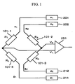
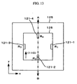
- Dispositif de mesure comportant :quatre résistances incluant des première à quatrième résistances (101-1 à 101-4 ; 121-1 à 121-4), au moins l'une des quatre résistances est un élément de transducteur dont la résistance change en fonction d'une quantité physique ambiante,une première borne à polarité positive (201),une première borne à polarité négative (211),une première borne de détection (V1),une seconde borne à polarité positive (202),une seconde borne à polarité négative (212),une seconde borne de détection (V2),deux connexions incluant des première et seconde connexions, la première connexion étant séquentiel-lement connectée à la première borne à polarité positive (201), à la première résistance (101-1 ; 121-1), à la première borne de détection (V1), à la quatrième résistance (101-4 ; 121-4), et à la première borne à polarité négative (211), et la seconde connexion étant séquentiellement connectée à la seconde borne à polarité positive (202), à la seconde résistance (101-2 ; 121-2), à la seconde borne de détection (V2), à la troisième résistance (101-3 ; 121-3), et à la seconde borne à polarité négative (212),un circuit configuré pour mesurer une tension de signal entre la première borne de détection (V1) et la seconde borne de détection (V2),un premier circuit d'attaque configuré pour appliquer une tension entre la première borne à polarité positive (201) et la première borne à polarité négative (211), etun second circuit d'attaque configuré pour appliquer une tension entre la seconde borne à polarité positive (202) et la seconde borne à polarité négative (212),caractérisé en ce que
les premier et second circuits d'attaque sont configurés de sorte qu'une tension délivrée par le premier circuit d'attaque diffère d'une tension délivrée par le second circuit d'attaque. - Dispositif de mesure selon la revendication 1, dans lequel l'élément de transducteur est un élément magnéto résistif dont la résistance change en fonction d'une direction ou d'une intensité d'un champ magnétique externe.
- Dispositif de mesure selon la revendication 1, dans lequel les au moins quatre résistances sont des éléments magnéto résistifs dont la résistance change en fonction d'une direction ou d'une intensité d'un champ magnétique externe.
- Dispositif de mesure selon la revendication 3, dans lequel
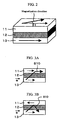
chacun des éléments magnéto résistifs est un élément magnéto résistif géant ayant une couche magnétique ancrée (13) avec une direction de magnétisation ancrée et une couche magnétique libre (11), et
les quatre éléments magnéto résistifs incluent deux éléments magnéto résistifs d'un premier type dont les couches magnétiques ancrées (13) sont magnétisées dans une première direction, et des éléments magnéto résistifs d'un second type dont les couches magnétiques ancrées (13) sont magnétisées dans une seconde direction. - Dispositif de mesure selon la revendication 3, dans lequel
chacun des éléments magnéto résistifs est un élément magnéto résistif anisotrope dont la résistance change en fonction d'un angle créé par une direction de flux de courant et une direction d'un champ magnétique à détecter. - Dispositif de mesure selon la revendication 1, dans lequel
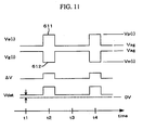
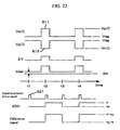
le premier circuit d'attaque inclut, pendant le fonctionnement du dispositif de mesure
, une période de tension nulle au cours de laquelle le circuit applique des potentiels égaux à la première borne à polarité positive (201) et à la première borne à polarité négative (211), et une période d'excitation au cours de laquelle le circuit applique différents potentiels à la première borne à polarité positive (201) et à la première borne à polarité négative (211), et
le second circuit d'attaque inclut, pendant le fonctionnement du dispositif de mesure
, une période de tension nulle au cours de laquelle le circuit applique des potentiels égaux à la seconde borne à polarité positive (202) et à la seconde borne à polarité négative (212), et une période d'excitation au cours de laquelle le circuit applique différents potentiels à la seconde borne à polarité positive (202) et à la seconde borne à polarité négative (212). - Dispositif de mesure selon la revendication 6, configuré de sorte qu'une tension de différence entre la tension de signal au cours de la période d'excitation et la tension de signal au cours de la période de tension nulle doit être mesurée.
- Dispositif de mesure selon la revendication 7, dans lequel une unité de traitement de signal de la tension de signal inclut une unité à retard (273) pour la tension de signal.
- Dispositif de mesure selon la revendication 8, dans lequel l'unité de traitement de signal inclut un générateur de synchronisation (278), le générateur de synchronisation (278) étant configuré pour générer un signal de synchronisation au cours de la période d'excitation et de la période de tension nulle et transmettre le signal de synchronisation à l'unité à retard (273).
- Dispositif de détection d'angle de rotation comportant le dispositif de mesure selon au moins l'une des revendications 2 à 9 et une unité de rotation sur laquelle un générateur de champ magnétique est monté.
- Dispositif de détection de position comportant le dispositif de mesure selon au moins l'une des revendications 2 à 9 et une unité de déplacement sur laquelle un générateur de champ magnétique est monté.
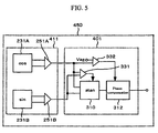
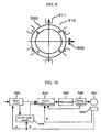
- Moteur comportant :un stator (510) ayant une bobine (511),un rotor (520) ayant un générateur de champ magnétique,un circuit d'attaque configuré pour délivrer un courant à la bobine (511), etun circuit de commande configuré pour commander le circuit d'attaque,dans lequel un signal de sortie du dispositif de mesure selon au moins l'une des revendications 2 à 9 est connecté au circuit de commande.
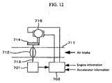
- Dispositif de commande de papillons des gaz comportant :un papillon des gaz (712),un arbre (713) sur lequel le papillon des gaz (712) est monté,un générateur de champ magnétique adapté pour tourner en association avec la rotation de l'arbre (713), etle dispositif de mesure selon au moins l'une des revendications 2 à 9.
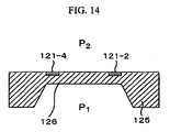
- Dispositif de mesure selon la revendication 1, dans lequel
l'élément de transducteur est un élément dont la résistance change par l'intermédiaire d'une tension mécanique, l'élément de transducteur étant disposé sur un diaphragme (126), et
le dispositif de mesure étant configuré pour mesurer une différence de pression entre des côtés opposés du diaphragme (126).
Applications Claiming Priority (1)
| Application Number | Priority Date | Filing Date | Title |
|---|---|---|---|
| JP2009045026A JP5156671B2 (ja) | 2009-02-27 | 2009-02-27 | 磁界検出装置および計測装置 |
Publications (3)
| Publication Number | Publication Date |
|---|---|
| EP2228663A2 EP2228663A2 (fr) | 2010-09-15 |
| EP2228663A3 EP2228663A3 (fr) | 2010-12-01 |
| EP2228663B1 true EP2228663B1 (fr) | 2012-06-27 |
Family
ID=42357793
Family Applications (1)
| Application Number | Title | Priority Date | Filing Date |
|---|---|---|---|
| EP10153888A Active EP2228663B1 (fr) | 2009-02-27 | 2010-02-17 | Appareil de détection de champ magnétique et appareil de mesure |
Country Status (3)
| Country | Link |
|---|---|
| US (1) | US8717017B2 (fr) |
| EP (1) | EP2228663B1 (fr) |
| JP (1) | JP5156671B2 (fr) |
Families Citing this family (26)
| Publication number | Priority date | Publication date | Assignee | Title |
|---|---|---|---|---|
| JP5096442B2 (ja) * | 2009-11-17 | 2012-12-12 | 株式会社日立製作所 | 回転角計測装置,モータシステム及び電動パワーステアリング・システム |
| US9506997B2 (en) | 2010-05-14 | 2016-11-29 | Hitachi, Ltd. | Magnetic-field-angle measurement apparatus and rotational-angle measurement apparatus using same |
| JP5380425B2 (ja) * | 2010-12-28 | 2014-01-08 | 日立オートモティブシステムズ株式会社 | 磁界角計測装置,回転角計測装置およびそれを用いた回転機,システム,車両および車両駆動装置 |
| US9157822B2 (en) * | 2011-02-01 | 2015-10-13 | Kulite Semiconductor Products, Inc. | Electronic interface for LVDT-type pressure transducers using piezoresistive sensors |
| CN202119390U (zh) * | 2011-03-03 | 2012-01-18 | 江苏多维科技有限公司 | 一种独立封装的桥式磁场角度传感器 |
| JP5427842B2 (ja) | 2011-06-30 | 2014-02-26 | 日立オートモティブシステムズ株式会社 | 回転角計測装置,制御装置およびそれらを用いた回転機システム |
| US8664941B2 (en) * | 2011-08-24 | 2014-03-04 | Nxp B.V. | Magnetic sensor with low electric offset |
| JP6222897B2 (ja) * | 2012-06-22 | 2017-11-01 | 旭化成エレクトロニクス株式会社 | 多軸磁気センサ、および、その製造方法 |
| JP6049570B2 (ja) * | 2013-08-27 | 2016-12-21 | アルプス電気株式会社 | 回転検出装置 |
| JP6190227B2 (ja) * | 2013-09-20 | 2017-08-30 | 株式会社東芝 | 圧力センサ、マイクロフォン、血圧センサ、携帯情報端末および補聴器 |
| US9176159B2 (en) * | 2013-10-03 | 2015-11-03 | Freescale Semiconductor Inc. | Variable reluctance sensor interfaces with signal pre-processing and methods of their operation |
| JP6255902B2 (ja) * | 2013-10-30 | 2018-01-10 | Tdk株式会社 | 磁界検出装置 |
| CN104656045B (zh) * | 2013-11-17 | 2018-01-09 | 爱盛科技股份有限公司 | 磁场感测模块、测量方法及磁场感测模块的制作方法 |
| JP2015179779A (ja) * | 2014-03-19 | 2015-10-08 | 株式会社東芝 | 歪検出素子、圧力センサ、マイクロフォン、血圧センサ及びタッチパネル |
| JP2017096627A (ja) * | 2014-03-28 | 2017-06-01 | コニカミノルタ株式会社 | 磁気センサー |
| EP2955492B1 (fr) * | 2014-06-13 | 2017-05-10 | Nxp B.V. | Système de capteur avec une configuration de pont complet de quatre éléments de détection résistifs |
| JP6608830B2 (ja) * | 2014-08-25 | 2019-11-20 | エヌエスディ株式会社 | 回転検出器 |
| DE102016103518A1 (de) * | 2016-02-29 | 2017-08-31 | Robert Bosch Automotive Steering Gmbh | Verfahren und Vorrichtung zur Rotorlagendiagnose in einem elektromotorischen Antrieb |
| JP2018146280A (ja) * | 2017-03-02 | 2018-09-20 | Tdk株式会社 | 磁気センサ |
| JP7396913B2 (ja) * | 2020-01-30 | 2023-12-12 | アズビル株式会社 | 圧力測定装置 |
| JP7341926B2 (ja) | 2020-03-11 | 2023-09-11 | 株式会社東芝 | 磁気センサ |
| CN112729622B (zh) * | 2020-12-17 | 2022-07-22 | 上海电气集团股份有限公司 | 一种应力无损检测方法、装置及设备 |
| CN112817143A (zh) * | 2020-12-31 | 2021-05-18 | 歌尔股份有限公司 | Mems扫描镜 |
| EP4108483A1 (fr) * | 2021-06-21 | 2022-12-28 | Volvo Truck Corporation | Dispositif de surveillance de charge utile pour véhicule à moteur |
| CN113607329B (zh) * | 2021-07-13 | 2022-10-18 | 复旦大学 | 压力传感器信号温度补偿方法及压力传感器 |
| WO2023220315A1 (fr) * | 2022-05-12 | 2023-11-16 | Hydra-Electric Company | Capteur de pression de configuration de demi-pont de sortie simulé lvdt |
Family Cites Families (31)
| Publication number | Priority date | Publication date | Assignee | Title |
|---|---|---|---|---|
| JPS6175214A (ja) * | 1984-09-20 | 1986-04-17 | Victor Co Of Japan Ltd | 磁気検出回路 |
| JPH03235002A (ja) * | 1990-02-09 | 1991-10-21 | Aisan Ind Co Ltd | スロットルポジションセンサ |
| JPH06261522A (ja) * | 1993-03-08 | 1994-09-16 | Sony Corp | 回転検出装置 |
| US5551301A (en) * | 1995-06-19 | 1996-09-03 | Cardiometrics, Inc. | Piezoresistive pressure transducer circuitry accommodating transducer variability |
| JP3004924B2 (ja) * | 1996-11-01 | 2000-01-31 | 株式会社ミツトヨ | 磁気エンコーダ |
| WO1998057188A1 (fr) * | 1997-06-13 | 1998-12-17 | Koninklijke Philips Electronics N.V. | Capteur muni d'un pont de wheatstone |
| JP3964037B2 (ja) * | 1998-03-20 | 2007-08-22 | 株式会社キーエンス | 圧力計の較正方法及び装置 |
| JP3605526B2 (ja) * | 1999-02-26 | 2004-12-22 | 株式会社東海理化電機製作所 | 回転検出センサの検出回路 |
| JP3609645B2 (ja) * | 1999-03-11 | 2005-01-12 | 株式会社東海理化電機製作所 | 回転検出センサ |
| DE60038332T2 (de) * | 1999-05-27 | 2009-04-30 | Radi Medical Systems Ab | Verfahren zur Temperaturkompensation in einem kombinierten Druck- und Temperatursensor |
| JP2002063682A (ja) * | 2000-08-21 | 2002-02-28 | Nec Corp | 走行位置検出装置 |
| JP4711248B2 (ja) * | 2000-09-20 | 2011-06-29 | センサータ テクノロジーズ インコーポレーテッド | センサの過剰な負のオフセットを検出するための方法および装置 |
| JP3839697B2 (ja) * | 2001-10-17 | 2006-11-01 | アルプス電気株式会社 | 回転角度センサ |
| JP2003302299A (ja) * | 2002-04-10 | 2003-10-24 | Denso Corp | 力学量検出装置の製造方法 |
| US6731032B1 (en) * | 2002-10-09 | 2004-05-04 | Dana Corporation | Electric motor with magnetic sensor wheel |
| US6765391B2 (en) * | 2002-10-22 | 2004-07-20 | Texas Instruments Incorporated | Low cost asic architecture for safety critical applications monitoring an applied stimulus |
| DE10308030B4 (de) * | 2003-02-24 | 2011-02-03 | Meas Deutschland Gmbh | Magnetoresistiver Sensor zur Bestimmung eines Winkels oder einer Position |
| JP4292571B2 (ja) * | 2003-03-31 | 2009-07-08 | 株式会社デンソー | 磁気センサの調整方法及び磁気センサの調整装置 |
| JP4259937B2 (ja) * | 2003-06-30 | 2009-04-30 | アルプス電気株式会社 | 角度検出センサ |
| EP1498744B1 (fr) * | 2003-07-18 | 2011-08-10 | Yamaha Corporation | Capteur magnétique et son procédé de fabrication |
| JP4224382B2 (ja) * | 2003-11-18 | 2009-02-12 | 株式会社日立製作所 | 回転位置センサ及び内燃機関の電子制御式スロットル装置 |
| JP4302558B2 (ja) * | 2004-03-17 | 2009-07-29 | 三菱電機株式会社 | 回転状態検出装置及び回転状態検出方法 |
| JP4419847B2 (ja) * | 2004-09-16 | 2010-02-24 | 株式会社デンソー | 圧力センサ |
| JP4232726B2 (ja) * | 2004-10-18 | 2009-03-04 | 株式会社デンソー | 回転検出装置 |
| JP4975972B2 (ja) | 2005-03-15 | 2012-07-11 | 日立オートモティブシステムズ株式会社 | 物理量センサ |
| JP2007078397A (ja) * | 2005-09-12 | 2007-03-29 | Mitsubishi Electric Corp | 半導体圧力センサ |
| JP4739164B2 (ja) * | 2006-10-20 | 2011-08-03 | 三菱電機株式会社 | 車両用エンジンの吸入空気圧力測定用の半導体感歪センサ |
| JP4991322B2 (ja) | 2006-10-30 | 2012-08-01 | 日立オートモティブシステムズ株式会社 | Gmr素子を用いた変位センサ,gmr素子を用いた角度検出センサ及びそれらに用いる半導体装置 |
| JP4900835B2 (ja) * | 2007-04-13 | 2012-03-21 | 日立金属株式会社 | 角度検出装置、バルブ装置および非接触式ボリューム |
| JP4992528B2 (ja) * | 2007-04-23 | 2012-08-08 | 株式会社デンソー | 回転センサ |
| JP4863953B2 (ja) * | 2007-08-30 | 2012-01-25 | 日立オートモティブシステムズ株式会社 | 物理量変換センサ及びそれを用いたモータ制御システム |
-
2009
- 2009-02-27 JP JP2009045026A patent/JP5156671B2/ja active Active
-
2010
- 2010-02-17 EP EP10153888A patent/EP2228663B1/fr active Active
- 2010-02-18 US US12/708,259 patent/US8717017B2/en active Active
Also Published As
| Publication number | Publication date |
|---|---|
| US20100219822A1 (en) | 2010-09-02 |
| JP5156671B2 (ja) | 2013-03-06 |
| JP2010197318A (ja) | 2010-09-09 |
| EP2228663A2 (fr) | 2010-09-15 |
| US8717017B2 (en) | 2014-05-06 |
| EP2228663A3 (fr) | 2010-12-01 |
Similar Documents
| Publication | Publication Date | Title |
|---|---|---|
| EP2228663B1 (fr) | Appareil de détection de champ magnétique et appareil de mesure | |
| US8471552B2 (en) | Rotational angle-measurement apparatus and rotational speed-measurement apparatus | |
| US8441252B2 (en) | Rotational angle measurement apparatus | |
| EP3828572B1 (fr) | Capteur de champ magnétique comprenant un module de correction d'angle | |
| KR101426877B1 (ko) | 회전 각도 검출 장치, 회전기 및 회전 각도 검출 방법 | |
| JP5427842B2 (ja) | 回転角計測装置,制御装置およびそれらを用いた回転機システム | |
| EP2871488B1 (fr) | Dispositif de compensation de force électromotrice de hall et méthode de compensation de force électromotrice de hall | |
| EP3457154B1 (fr) | Rejet de champ parasite dans des capteurs magnétiques | |
| US20110202295A1 (en) | Current measuring device | |
| US20130264915A1 (en) | Magnetic Field Angle Measurement Apparatus, Rotation Angle Measurement Apparatus, and Rotation Machine, System, Vehicle, and Vehicle Drive Apparatus Each Using Same Rotation Angle Measurement Apparatus | |
| CN109212439B (zh) | 磁场传感器 | |
| US10267870B2 (en) | Detecting sensor error | |
| US10759276B2 (en) | Magnetic sensor and detection device using same | |
| JP5705705B2 (ja) | 磁界角計測装置およびそれを用いた回転機 | |
| JP2016514833A (ja) | 外部磁界に対して鈍感なホールセンサ | |
| JP5439595B2 (ja) | 磁界角計測装置およびこれを用いた回転角計測装置 | |
| JPWO2014006914A1 (ja) | 電流センサの製造方法及び電流センサ | |
| US20220113164A1 (en) | Sensor system, system and method for determining a position or a rotational angle | |
| CN101010593A (zh) | 集成磁阻速度和方向传感器 | |
| KR20170026209A (ko) | 인코더 | |
| CN109870247B (zh) | 感测系统、测量方法以及包括感测系统的检测系统和交通工具 | |
| WO2015002155A1 (fr) | Dispositif d'estimation de température d'aimant et procédé d'estimation de température d'aimant | |
| US20230258515A1 (en) | Magnetic field differential torque sensor | |
| US11536748B2 (en) | Current sensor | |
| US20140125328A1 (en) | Magnetic detection device |
Legal Events
| Date | Code | Title | Description |
|---|---|---|---|
| PUAI | Public reference made under article 153(3) epc to a published international application that has entered the european phase |
Free format text: ORIGINAL CODE: 0009012 |
|
| 17P | Request for examination filed |
Effective date: 20100528 |
|
| AK | Designated contracting states |
Kind code of ref document: A2 Designated state(s): AT BE BG CH CY CZ DE DK EE ES FI FR GB GR HR HU IE IS IT LI LT LU LV MC MK MT NL NO PL PT RO SE SI SK SM TR |
|
| PUAL | Search report despatched |
Free format text: ORIGINAL CODE: 0009013 |
|
| AK | Designated contracting states |
Kind code of ref document: A3 Designated state(s): AT BE BG CH CY CZ DE DK EE ES FI FR GB GR HR HU IE IS IT LI LT LU LV MC MK MT NL NO PL PT RO SE SI SK SM TR |
|
| RIC1 | Information provided on ipc code assigned before grant |
Ipc: G01D 5/244 20060101ALI20101025BHEP Ipc: G01D 5/14 20060101ALI20101025BHEP Ipc: G01R 33/09 20060101AFI20100804BHEP |
|
| RIC1 | Information provided on ipc code assigned before grant |
Ipc: G01D 5/14 20060101ALI20110909BHEP Ipc: G01D 5/244 20060101ALI20110909BHEP Ipc: G01R 33/09 20060101AFI20110909BHEP |
|
| GRAP | Despatch of communication of intention to grant a patent |
Free format text: ORIGINAL CODE: EPIDOSNIGR1 |
|
| GRAJ | Information related to disapproval of communication of intention to grant by the applicant or resumption of examination proceedings by the epo deleted |
Free format text: ORIGINAL CODE: EPIDOSDIGR1 |
|
| GRAP | Despatch of communication of intention to grant a patent |
Free format text: ORIGINAL CODE: EPIDOSNIGR1 |
|
| GRAS | Grant fee paid |
Free format text: ORIGINAL CODE: EPIDOSNIGR3 |
|
| GRAA | (expected) grant |
Free format text: ORIGINAL CODE: 0009210 |
|
| RIN1 | Information on inventor provided before grant (corrected) |
Inventor name: KANEKAWA, NOBUYASU Inventor name: SUZUKI, MUTSUMI Inventor name: YAMADA, MASAMICHI |
|
| AK | Designated contracting states |
Kind code of ref document: B1 Designated state(s): AT BE BG CH CY CZ DE DK EE ES FI FR GB GR HR HU IE IS IT LI LT LU LV MC MK MT NL NO PL PT RO SE SI SK SM TR |
|
| REG | Reference to a national code |
Ref country code: GB Ref legal event code: FG4D |
|
| REG | Reference to a national code |
Ref country code: CH Ref legal event code: EP |
|
| REG | Reference to a national code |
Ref country code: AT Ref legal event code: REF Ref document number: 564502 Country of ref document: AT Kind code of ref document: T Effective date: 20120715 |
|
| REG | Reference to a national code |
Ref country code: IE Ref legal event code: FG4D |
|
| REG | Reference to a national code |
Ref country code: NL Ref legal event code: T3 |
|
| REG | Reference to a national code |
Ref country code: DE Ref legal event code: R096 Ref document number: 602010001999 Country of ref document: DE Effective date: 20120823 |
|
| PG25 | Lapsed in a contracting state [announced via postgrant information from national office to epo] |
Ref country code: FI Free format text: LAPSE BECAUSE OF FAILURE TO SUBMIT A TRANSLATION OF THE DESCRIPTION OR TO PAY THE FEE WITHIN THE PRESCRIBED TIME-LIMIT Effective date: 20120627 Ref country code: LT Free format text: LAPSE BECAUSE OF FAILURE TO SUBMIT A TRANSLATION OF THE DESCRIPTION OR TO PAY THE FEE WITHIN THE PRESCRIBED TIME-LIMIT Effective date: 20120627 Ref country code: NO Free format text: LAPSE BECAUSE OF FAILURE TO SUBMIT A TRANSLATION OF THE DESCRIPTION OR TO PAY THE FEE WITHIN THE PRESCRIBED TIME-LIMIT Effective date: 20120927 Ref country code: SE Free format text: LAPSE BECAUSE OF FAILURE TO SUBMIT A TRANSLATION OF THE DESCRIPTION OR TO PAY THE FEE WITHIN THE PRESCRIBED TIME-LIMIT Effective date: 20120627 |
|
| REG | Reference to a national code |
Ref country code: AT Ref legal event code: MK05 Ref document number: 564502 Country of ref document: AT Kind code of ref document: T Effective date: 20120627 |
|
| REG | Reference to a national code |
Ref country code: LT Ref legal event code: MG4D Effective date: 20120627 |
|
| PG25 | Lapsed in a contracting state [announced via postgrant information from national office to epo] |
Ref country code: LV Free format text: LAPSE BECAUSE OF FAILURE TO SUBMIT A TRANSLATION OF THE DESCRIPTION OR TO PAY THE FEE WITHIN THE PRESCRIBED TIME-LIMIT Effective date: 20120627 Ref country code: SI Free format text: LAPSE BECAUSE OF FAILURE TO SUBMIT A TRANSLATION OF THE DESCRIPTION OR TO PAY THE FEE WITHIN THE PRESCRIBED TIME-LIMIT Effective date: 20120627 Ref country code: HR Free format text: LAPSE BECAUSE OF FAILURE TO SUBMIT A TRANSLATION OF THE DESCRIPTION OR TO PAY THE FEE WITHIN THE PRESCRIBED TIME-LIMIT Effective date: 20120627 Ref country code: GR Free format text: LAPSE BECAUSE OF FAILURE TO SUBMIT A TRANSLATION OF THE DESCRIPTION OR TO PAY THE FEE WITHIN THE PRESCRIBED TIME-LIMIT Effective date: 20120928 |
|
| PG25 | Lapsed in a contracting state [announced via postgrant information from national office to epo] |
Ref country code: BE Free format text: LAPSE BECAUSE OF FAILURE TO SUBMIT A TRANSLATION OF THE DESCRIPTION OR TO PAY THE FEE WITHIN THE PRESCRIBED TIME-LIMIT Effective date: 20120627 Ref country code: SK Free format text: LAPSE BECAUSE OF FAILURE TO SUBMIT A TRANSLATION OF THE DESCRIPTION OR TO PAY THE FEE WITHIN THE PRESCRIBED TIME-LIMIT Effective date: 20120627 Ref country code: RO Free format text: LAPSE BECAUSE OF FAILURE TO SUBMIT A TRANSLATION OF THE DESCRIPTION OR TO PAY THE FEE WITHIN THE PRESCRIBED TIME-LIMIT Effective date: 20120627 Ref country code: EE Free format text: LAPSE BECAUSE OF FAILURE TO SUBMIT A TRANSLATION OF THE DESCRIPTION OR TO PAY THE FEE WITHIN THE PRESCRIBED TIME-LIMIT Effective date: 20120627 Ref country code: CZ Free format text: LAPSE BECAUSE OF FAILURE TO SUBMIT A TRANSLATION OF THE DESCRIPTION OR TO PAY THE FEE WITHIN THE PRESCRIBED TIME-LIMIT Effective date: 20120627 Ref country code: CY Free format text: LAPSE BECAUSE OF FAILURE TO SUBMIT A TRANSLATION OF THE DESCRIPTION OR TO PAY THE FEE WITHIN THE PRESCRIBED TIME-LIMIT Effective date: 20120627 Ref country code: AT Free format text: LAPSE BECAUSE OF FAILURE TO SUBMIT A TRANSLATION OF THE DESCRIPTION OR TO PAY THE FEE WITHIN THE PRESCRIBED TIME-LIMIT Effective date: 20120627 Ref country code: IS Free format text: LAPSE BECAUSE OF FAILURE TO SUBMIT A TRANSLATION OF THE DESCRIPTION OR TO PAY THE FEE WITHIN THE PRESCRIBED TIME-LIMIT Effective date: 20121027 |
|
| PG25 | Lapsed in a contracting state [announced via postgrant information from national office to epo] |
Ref country code: PL Free format text: LAPSE BECAUSE OF FAILURE TO SUBMIT A TRANSLATION OF THE DESCRIPTION OR TO PAY THE FEE WITHIN THE PRESCRIBED TIME-LIMIT Effective date: 20120627 Ref country code: IT Free format text: LAPSE BECAUSE OF FAILURE TO SUBMIT A TRANSLATION OF THE DESCRIPTION OR TO PAY THE FEE WITHIN THE PRESCRIBED TIME-LIMIT Effective date: 20120627 Ref country code: PT Free format text: LAPSE BECAUSE OF FAILURE TO SUBMIT A TRANSLATION OF THE DESCRIPTION OR TO PAY THE FEE WITHIN THE PRESCRIBED TIME-LIMIT Effective date: 20121029 |
|
| PG25 | Lapsed in a contracting state [announced via postgrant information from national office to epo] |
Ref country code: DK Free format text: LAPSE BECAUSE OF FAILURE TO SUBMIT A TRANSLATION OF THE DESCRIPTION OR TO PAY THE FEE WITHIN THE PRESCRIBED TIME-LIMIT Effective date: 20120627 Ref country code: ES Free format text: LAPSE BECAUSE OF FAILURE TO SUBMIT A TRANSLATION OF THE DESCRIPTION OR TO PAY THE FEE WITHIN THE PRESCRIBED TIME-LIMIT Effective date: 20121008 |
|
| PLBE | No opposition filed within time limit |
Free format text: ORIGINAL CODE: 0009261 |
|
| STAA | Information on the status of an ep patent application or granted ep patent |
Free format text: STATUS: NO OPPOSITION FILED WITHIN TIME LIMIT |
|
| 26N | No opposition filed |
Effective date: 20130328 |
|
| REG | Reference to a national code |
Ref country code: DE Ref legal event code: R097 Ref document number: 602010001999 Country of ref document: DE Effective date: 20130328 |
|
| PG25 | Lapsed in a contracting state [announced via postgrant information from national office to epo] |
Ref country code: BG Free format text: LAPSE BECAUSE OF FAILURE TO SUBMIT A TRANSLATION OF THE DESCRIPTION OR TO PAY THE FEE WITHIN THE PRESCRIBED TIME-LIMIT Effective date: 20120927 |
|
| PG25 | Lapsed in a contracting state [announced via postgrant information from national office to epo] |
Ref country code: MC Free format text: LAPSE BECAUSE OF NON-PAYMENT OF DUE FEES Effective date: 20130228 |
|
| REG | Reference to a national code |
Ref country code: IE Ref legal event code: MM4A |
|
| PG25 | Lapsed in a contracting state [announced via postgrant information from national office to epo] |
Ref country code: IE Free format text: LAPSE BECAUSE OF NON-PAYMENT OF DUE FEES Effective date: 20130217 |
|
| PG25 | Lapsed in a contracting state [announced via postgrant information from national office to epo] |
Ref country code: MT Free format text: LAPSE BECAUSE OF FAILURE TO SUBMIT A TRANSLATION OF THE DESCRIPTION OR TO PAY THE FEE WITHIN THE PRESCRIBED TIME-LIMIT Effective date: 20120627 |
|
| REG | Reference to a national code |
Ref country code: CH Ref legal event code: PL |
|
| PG25 | Lapsed in a contracting state [announced via postgrant information from national office to epo] |
Ref country code: CH Free format text: LAPSE BECAUSE OF NON-PAYMENT OF DUE FEES Effective date: 20140228 Ref country code: LI Free format text: LAPSE BECAUSE OF NON-PAYMENT OF DUE FEES Effective date: 20140228 |
|
| PG25 | Lapsed in a contracting state [announced via postgrant information from national office to epo] |
Ref country code: SM Free format text: LAPSE BECAUSE OF FAILURE TO SUBMIT A TRANSLATION OF THE DESCRIPTION OR TO PAY THE FEE WITHIN THE PRESCRIBED TIME-LIMIT Effective date: 20120627 |
|
| PG25 | Lapsed in a contracting state [announced via postgrant information from national office to epo] |
Ref country code: TR Free format text: LAPSE BECAUSE OF FAILURE TO SUBMIT A TRANSLATION OF THE DESCRIPTION OR TO PAY THE FEE WITHIN THE PRESCRIBED TIME-LIMIT Effective date: 20120627 |
|
| PG25 | Lapsed in a contracting state [announced via postgrant information from national office to epo] |
Ref country code: MK Free format text: LAPSE BECAUSE OF FAILURE TO SUBMIT A TRANSLATION OF THE DESCRIPTION OR TO PAY THE FEE WITHIN THE PRESCRIBED TIME-LIMIT Effective date: 20120627 Ref country code: HU Free format text: LAPSE BECAUSE OF FAILURE TO SUBMIT A TRANSLATION OF THE DESCRIPTION OR TO PAY THE FEE WITHIN THE PRESCRIBED TIME-LIMIT; INVALID AB INITIO Effective date: 20100217 Ref country code: LU Free format text: LAPSE BECAUSE OF NON-PAYMENT OF DUE FEES Effective date: 20130217 |
|
| REG | Reference to a national code |
Ref country code: FR Ref legal event code: PLFP Year of fee payment: 7 |
|
| REG | Reference to a national code |
Ref country code: FR Ref legal event code: PLFP Year of fee payment: 8 |
|
| REG | Reference to a national code |
Ref country code: FR Ref legal event code: PLFP Year of fee payment: 9 |
|
| PGFP | Annual fee paid to national office [announced via postgrant information from national office to epo] |
Ref country code: FR Payment date: 20230110 Year of fee payment: 14 |
|
| PGFP | Annual fee paid to national office [announced via postgrant information from national office to epo] |
Ref country code: NL Payment date: 20240108 Year of fee payment: 15 |
|
| PGFP | Annual fee paid to national office [announced via postgrant information from national office to epo] |
Ref country code: DE Payment date: 20231228 Year of fee payment: 15 Ref country code: GB Payment date: 20240109 Year of fee payment: 15 |