EP2221409B1 - Dispositif de retenue pour un outil destiné au traitement d'une structure plate textile ou non textile d'une machine à coudre - Google Patents
Dispositif de retenue pour un outil destiné au traitement d'une structure plate textile ou non textile d'une machine à coudre Download PDFInfo
- Publication number
- EP2221409B1 EP2221409B1 EP10405007A EP10405007A EP2221409B1 EP 2221409 B1 EP2221409 B1 EP 2221409B1 EP 10405007 A EP10405007 A EP 10405007A EP 10405007 A EP10405007 A EP 10405007A EP 2221409 B1 EP2221409 B1 EP 2221409B1
- Authority
- EP
- European Patent Office
- Prior art keywords
- holding device
- tool
- tool holder
- textile
- presser foot
- Prior art date
- Legal status (The legal status is an assumption and is not a legal conclusion. Google has not performed a legal analysis and makes no representation as to the accuracy of the status listed.)
- Active
Links
- 238000009958 sewing Methods 0.000 title claims abstract description 67
- 239000004753 textile Substances 0.000 title claims abstract description 49
- 239000000463 material Substances 0.000 claims abstract description 19
- 230000008878 coupling Effects 0.000 claims abstract description 15
- 238000010168 coupling process Methods 0.000 claims abstract description 15
- 238000005859 coupling reaction Methods 0.000 claims abstract description 15
- 230000005540 biological transmission Effects 0.000 claims abstract description 11
- 238000000034 method Methods 0.000 claims abstract description 11
- 230000033001 locomotion Effects 0.000 claims description 30
- 230000007246 mechanism Effects 0.000 claims description 6
- 230000009471 action Effects 0.000 claims description 4
- 239000006096 absorbing agent Substances 0.000 claims description 3
- 230000035939 shock Effects 0.000 claims description 3
- 230000000694 effects Effects 0.000 claims 2
- 239000003550 marker Substances 0.000 abstract 1
- 239000004744 fabric Substances 0.000 description 28
- 239000003086 colorant Substances 0.000 description 2
- 239000003973 paint Substances 0.000 description 2
- 230000008569 process Effects 0.000 description 2
- 230000006978 adaptation Effects 0.000 description 1
- 239000000853 adhesive Substances 0.000 description 1
- 230000001070 adhesive effect Effects 0.000 description 1
- 230000008901 benefit Effects 0.000 description 1
- 230000015572 biosynthetic process Effects 0.000 description 1
- 125000004122 cyclic group Chemical group 0.000 description 1
- 238000013016 damping Methods 0.000 description 1
- 238000009956 embroidering Methods 0.000 description 1
- 238000010438 heat treatment Methods 0.000 description 1
- 238000010186 staining Methods 0.000 description 1
Images
Classifications
-
- D—TEXTILES; PAPER
- D05—SEWING; EMBROIDERING; TUFTING
- D05C—EMBROIDERING; TUFTING
- D05C13/00—Auxiliary devices incorporated in embroidering machines, not otherwise provided for; Ancillary apparatus for use with embroidering machines
-
- D—TEXTILES; PAPER
- D05—SEWING; EMBROIDERING; TUFTING
- D05B—SEWING
- D05B35/00—Work-feeding or -handling elements not otherwise provided for
Definitions
- the invention relates to a holding device for a tool for processing a textile or non-textile fabric in a sewing machine and a method for processing the sheet with the tool according to the features of the claims 1 and 9.
- Sewing machines and embroidery machines each comprise a stitch forming device for creating seams or embroidery patterns in a textile fabric or sewing material.
- the sewing material is moved in a plane below a machine head relative to a sewing needle or moved stepwise.
- the suture needle is releasably connected to a needle holder located at the lower end of a needle bar.
- the needle bar protrudes at the bottom of the machine head and is movable up and down in the axial direction by a needle bar drive, such that the sewing needle can execute sewing stitches.
- a Nähfussstange down at the machine head It usually comprises a conical or tapered tapered lower end for coupling and attaching various presser feet.
- Each of the presser feet includes one with the conical end of the presser foot bar corresponding shaft and can be easily placed from below on the Nähfussstange.
- the presser foot is automatically centered and optionally brought by further alignment in a predetermined desired position. There he can be fixed for example by means of a retaining clip or other fastener.
- Such presser feet are known in different embodiments - depending on the nature of the stitches to be executed. For sewing, the presser foot is lowered with the presser foot in such a way that the foot of the presser foot rests on the sewing material. The presser foot is pushed down by the force of a spring so that the foot of the presser foot is pressed resiliently onto the upper side of the sewing material.
- the sewing needle with the upper thread is at least approximately inserted vertically into the sewing material to the sewing material and pulled out in the opposite direction again.
- the sewing material can be moved, for example by a feed dog before the execution of the next stitch in the required new position.
- the fabric may also be clamped in an embroidery frame.
- an xy-movement device of the embroidery frame is gradually shifted, so that in each case the next puncture site of the material comes to rest under the sewing needle.
- the movements of the hoop are controlled by the sewing machine control or alternatively by a PC or by an external control and are coordinated with the stitch movements of Needle bar.
- the stuffing or quilting the material is manually moved in the Nähgutebene.
- a disadvantage of this method is that this device can only be used with specially equipped sewing machines.
- the stroke of the Hüpfermechanismus is relatively small. This can lead to problems especially with thick fabrics or with several fabric layers.
- an apparatus for sewing zig-zag stitches which can be used in sewing machines, which are designed only for sewing straight seams, since their needle bars can only perform up and down movements, but no pivoting movements across to the sewing direction.
- the device comprises a presser foot with a base which can be fastened to the needle bar and a guide device which is mounted at this base so as to be pivotable transversely to the sewing direction for holding down and guiding the work piece during sewing.
- a lever mechanism which can be coupled with the needle bar, the guide device is pivoted back and forth in a manner transverse to the sewing direction as a function of the movements of the needle bar so that the puncture sites on the sewing material form a zigzag pattern.
- An object of the present invention is to provide an improved apparatus and method for applying paint to a fabric using any commercially available sewing machine.
- a further object of the invention is to design the device and the method such that commercial textile pens or pens can be used to apply the colors or to print the fabric.
- a further object of the invention is to design the apparatus and method such that other processing tools can be used instead of pens, and that instead of applying paint - according to the particular tools used - the sheet can be processed in other ways ,
- the holding device is attached to the sewing foot bar of the sewing machine analogously to a commercially available presser foot.
- the holding device comprises a tool holder for receiving and securing a commercial textile writer or alternatively another tool.
- the tool holder is pivotally or otherwise guided out movably or displaceably held on a base part.
- the needle bar or a transmission part connected to the needle bar comes into contact with a coupling element on the tool holder during lowering or during a stitch movement.
- By the action of force of the needle bar or the transmission part on the coupling element of the tool holder with the tool performs a movement according to or predetermined by the guide movement degrees of freedom.
- the tool holder is spring-loaded such that it is held without additional force by the needle bar in a basic position on the base part or returns to this basic position when the force of the needle bar is eliminated.
- the holding device is designed so that the tool holder against the spring force of a return spring by a few millimeters guided parallel to the Nähfussachse is shifted downwards, when the lower end of the needle bar or a transfer element held thereon such as a part of the needle holder during the downward movement shortly before the lower inflection point impinges on a designated coupling element region of the tool holder.
- the transmission element comprises a shock absorber or an elastically resilient element, such as a spring, in order to damp or cushion the impacts of the needle bar.
- a shock absorber or an elastically resilient element such as a spring
- the movement of the needle bar can be used, as otherwise provided in a conventional sewing or embroidery process.
- a pivoting movement of the needle bar as is conventionally used in zig-zag stitches, could also be used to transmit the motion to the tool holder.
- the holding device of the tool holder is designed for receiving commercially available textile pins. It may, for example, include interchangeable adapters for fixing such pins in a defined position, such that the writing tip lies at the intersection of the pin axis and the needle bar axis and that instead of puncturing sites of the sewing needle color points of the textile writer are formed on the fabric.
- the tool holder or the Adapter also be designed so that the writing tip of the textile writer is arranged slightly offset radially to the extended needle bar axis. In this case, it is possible to form color dots with the textile writer on the sewing material parallel to the sewing stitches even when the sewing needle is inserted into the needle holder.
- the tool holder is preferably designed such that the axis of the textile writer fixed therein is arranged inclined to the needle bar axis. In this way, the length of the usable textile writer is not limited by the distance between the machine head and the fabric.
- the holding device may comprise an adjusting mechanism, which allows to limit the range of movement of the tool holder. For example, limits for the positions of the basic position and / or the end position of the tool holder with respect to the base part can be set with the adjusting mechanism.
- the adjustment mechanism can be used, for example, for adjusting the height position of the textile writer relative to the sheet to be processed.
- the adjusting device may comprise means for adjusting the mutual position of two relatively movable objects, wherein at least one of these objects is an element of the holding device. Examples of such pairs of objects are squeeze bar base, base part tool holder, tool holder adapter (for tool); Tool holder tool.
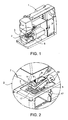
- FIG. 1 shows a partially cut-open sewing machine 1 with a connected thereto holding device 3 for a textile writer 5.
- the framed by a circular line 2 portion is in FIG. 2 shown enlarged.
- At the bottom of the machine head 7 protrudes one Needle bar 9, which is movable up and down by a needle bar drive in the vertical direction or in the direction of the needle bar axis 8.
- At the lower end of the needle bar 9 is a needle holder 11 for releasably securing a sewing needle 13 (FIG. Fig. 5 ) firmly connected to the needle bar 9.
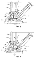
- FIG. 3 shows the arrangement FIG. 1 in a partially cutaway side view.
- the holding device 3 comprises a base part 19 with a Nähfussschaft 21 for attachment to the usually conically shaped lower end of a Nähfussstange 23.
- the base member 19 is connected analogously to a presser foot, for example by means of a fixing lever 25 fixed to the Nähfussstange 23.
- the base part 19 comprises a first guide pin 27.
- first guide pin 27 protrudes downwards parallel to the presser foot axis 24 into a corresponding first bore 29 on a first leg 15a of the tool holder 15 aligned parallel to the throat plate 17.
- a second guide pin 31 extends parallel to the first guide pin 27 upwards into a corresponding second bore (not visible) on the base part 19.
- the first Bore 29 and the second bore are formed as bearings for the respective guide pins 27, 31.
- other linear guide elements and correspondingly adapted bearings can be provided.
- a recess is formed on the base portion 19 which exposes the second bore in a central portion of the base portion 19 and exposes a lower abutment surface 33a and an upper abutment surface 33b on the base portion 19 adjacent to the second bore.
- a coil spring 35 between the lower stop surface 33a and a second guide pin 31 radially projecting limiting means, such as a Seegering 37, held with slight bias, that the Seeger ring 37 is present at the upper stop surface 33b.
- the spring constant or the force of Coil spring 35 is dimensioned so that it is able to raise the tool holder 15 with the tool held therein - in the present example, this is the textile writer 5 - quickly and reliably in the normal position.
- the holding device 3 is designed so that the movement of the needle bar 9 of the sewing machine 1, as it takes place during sewing, can be used to move the tool holder 15 with the tool mounted therein in the manner described.
- the tool holder 15 comprises a coupling device 39 which is designed and arranged such that the needle bar 9 or another transmission element 41 formed on the needle bar 9 or connected thereto can transmit kinetic energy to the tool holder 15.
- the transmission element 41 is the underside of the needle holder 11.
- the coupling device 39 is designed and arranged such that the transmission element 41 performs at least a portion of this movement cycle when performing an up-and-down movement of the needle bar 9, as in sewing 'Is coupled to the coupling device 39 and so is able to move the tool holder 15 according to the predetermined guidance.
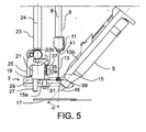
- the coupling device 39 could be formed directly as part of the first leg 15a of the tool holder 15, wherein the extended needle bar axis 8 intersects this portion.
- the coupling device 39 comprises a shock absorber or an elastically resilient element, such as a spring, in order to damp or cushion the impacts of the needle bar 9 or of the transmission element 41 held thereon when it strikes the first leg 15a.
- a damping or spring member could alternatively also be formed on the side of the needle bar 9 or on the transmission element 41.
- Such a resilient element can also cause a spring-loaded or elastic pressing of the tool on the workpiece to be processed at the same time.
- the tool holder 15 includes adjacent to the first leg 15 a second leg 15 b.
- the two legs 15a, 15b enclose an angle of 90 ° + ⁇ , such that a textile scribe 5 fixed axially parallel to the second leg 15b is inclined at an inclination angle ⁇ with respect to the needle bar axis 8. It is assumed that the needle bar axis 8 is aligned vertically to the surface of the needle plate 17 and the sheet 44 or fabric lying thereon.
- the inclination angle ⁇ is greater than or equal to 0 °. It may for example be about 45 ° and is preferably in a range of about 30 ° to about 60 °.
- the position or orientation of the second leg 15b relative to the first leg 15a can fixed or alternatively-by means of a continuously or in stages adjustable adjustment (not shown) can be set.
- a tool holder 15 may also be designed so that the textile writer 5 or the tool in a basic position of the tool holder 15 rests passively on the sheet 44 or is pressed onto this, and is lifted by the action of the needle bar 9 from the fabric 44.
- the tool holder 15 can also be articulated permanently or releasably connected to the needle bar 9 and / or the Nähfussstange 23 (no representation).
- the tool holder 15 can also be designed to fasten any other tools, such as, for example, cutting knives, adhesive cartridges or a laser for material processing.
- any other tools such as, for example, cutting knives, adhesive cartridges or a laser for material processing.
- active tools such as lasers, motor-operated scissors and the like can thus be expressly used, which are supplied with energy, for example via a connection cable for sewing machine control, and optionally controlled by the sewing machine control.
- the tool holder 15 with the tool can preferably be arranged and aligned in any position relative to the base part 19.
- an adjusting device (not shown) is preferably provided, which allows, for example by means of an adjusting screw to adjust the height level of the pen tip 45 relative to the first leg 15a.
- the pressing force of the pen tip 45th be adjusted against the throat plate 17. If a fabric 44 lies on the stitch plate 17, the contact force of the writing tip 45 on the fabric 44 can be changed in an analogous manner and adapted to the thickness and type of the fabric 44.
- this can include, for example exchangeable inserts or adapter 47 and resilient clamping means 49.
- a cuff-shaped adapter 47 in the region of the pen tip 45 and resilient retaining clips are shown as clamping means 49 in the rear region of the second leg 15b.
- a stop is formed, which prevents the textile pin 5 can move axially during operation.
- the stop may also be designed to be resilient and / or adjustable in its position. As a result, an adaptation to different textile pins 5 is possible.
- FIG. 5 shows an arrangement according to FIG. 3
- the sewing needle 13 is a multiple sewing needle in which none of the individual sewing needles 13 is coaxial with the needle bar axis 8
- the writing tip 45 of the textile pen 5 may be as shown in FIG FIG. 5 represented without radial offset with respect to the extended needle bar axis 8 are arranged.
- the tool holder 15 or the adapter be designed or aligned so that the pen tip 45 with respect to the needle bar axis 8 has a radial offset, which may be of the order of, for example, about one millimeter to about 25mm and is optionally adjustable.
- the tool holder 15 or parts thereof such as e.g. one or more adapters 47 may also be designed to receive and fix other tools instead of textile pens 5 (not shown).
- a generated by the zigzag drive of the sewing machine 1 pivotal or pendulum motion of the needle bar 9 to a movement or other action of the to cause or influence the tool holder 15 held tool can be used in further embodiments of the invention.
- a tool may include not only passive elements but also active components, such as a laser light source for locally heating the sheet 44 or a piezoelectric vibrator for a cutting knife (not shown).
Landscapes
- Engineering & Computer Science (AREA)
- Textile Engineering (AREA)
- Sewing Machines And Sewing (AREA)
- Treatment Of Fiber Materials (AREA)
Claims (10)
- Dispositif de retenue (3) pour un outil pour le traitement d'une texture surfacique textile ou non textile (44) dans une machine à coudre (1), caractérisé en ce que, sur une partie de base (19), un pied d'embase de couture (21) pour la fixation du dispositif de retenue (3) est réalisé sur une tige d'embase de couture (23) de la machine à coudre (1), et en ce qu'un porte-outil (15) réalisé pour la réception de l'outil est maintenu sur la partie de base (19), et en ce que le porte-outil (15) comporte un dispositif d'accouplement (39) pour l'influence par un élément de transmission (11) réalisé sur la tige d'aiguille (9).
- Dispositif de retenue (3) selon la revendication 1, caractérisé en ce que le porte-outil (15) est réalisé pour réceptionner ou pour maintenir des marqueurs textiles usuels dans le commerce.
- Dispositif de retenue (3) selon l'une ou l'autre des revendications 1 et 2, caractérisé en ce que le porte-outil (15) sur la partie de base (19) est maintenu avec faculté de déplacement et en ce que le dispositif d'accouplement (39) est agencé et orienté sur le porte-outil (15) de telle sorte que, lorsque le dispositif de retenue (3) est fixé sur la tige d'embase de couture (23) de la machine à coudre (1), il peut être déplacé par le mouvement de la tige d'aiguille (9).
- Dispositif de retenue (3) selon l'une des revendications 1 à 3, caractérisé en ce que le dispositif d'accouplement (39) comporte un amortisseur de chocs ou un élément à suspension élastique.
- Dispositif de retenue (3) selon l'une des revendications 1 à 4, caractérisé en ce que le porte-outil (15) comporte un premier montant (15a) et un second montant (15b) et en ce que le premier montant (15a) est monté avec faculté de déplacement sur la partie de base (19) et en ce que le second montant (15b) est relié au premier montant (15a) sous l'inclusion d'un angle d'inclinaison fixe ou réglable (90° + α).
- Dispositif de retenue (3) selon la revendication 5, caractérisé en ce que le second montant (15b) comporte des moyens pour la fixation à nouveau déverrouillée de l'outil dans une position prédéfinie.
- Dispositif de retenue (3) selon la revendication 6, caractérisé en ce que les moyens destinés à prescrire la position de l'outil comportent un adaptateur remplaçable (47).
- Dispositif de retenue (3) selon l'une des revendications 1 à 7, caractérisé en ce qu'un mécanisme d'ajustage est prévu pour limiter une zone de mouvement et/ou pour influencer sur une position relative.
- Dispositif de retenue (3) selon l'une des revendications 1 à 8, caractérisé en ce que, sur la partie de base (19) et/ou sur le porte-outil (15), un boulon de guidage (27, 31) ou un autre élément de guidage linéaire correspondant est réalisé, de telle sorte que le porte-outil (15) est monté avec faculté de déplacement sur la partie de base (19) lors d'un dispositif de retenue (3) relié parallèlement à la tige d'embase de couture (23) de la machine à coudre (1) et en ce que le porte-outil (15) est maintenu sur la partie de base (19) sans l'influence d'autres forces par la force d'un ressort dans une position de base ou dans une première position de travail.
- Procédé pour traiter une texture surfacique textile ou non textile (44) avec un outil, caractérisé en ce que l'outil est fixé au moyen d'un dispositif de retenue (3) conformément à l'une des revendications 1 à 9 sur la tige d'embase de couture (23) et qu'il est déplacé par l'action du mouvement de la tige d'aiguille ou qu'il est modifié dans son activité.
Applications Claiming Priority (1)
| Application Number | Priority Date | Filing Date | Title |
|---|---|---|---|
| CH00204/09A CH700377A1 (de) | 2009-02-11 | 2009-02-11 | Haltevorrichtung für ein Werkzeug zur Bearbeitung eines textilen oder nicht textilen Flächengebildes bei einer Nähmaschine. |
Publications (2)
| Publication Number | Publication Date |
|---|---|
| EP2221409A1 EP2221409A1 (fr) | 2010-08-25 |
| EP2221409B1 true EP2221409B1 (fr) | 2012-03-21 |
Family
ID=42236340
Family Applications (1)
| Application Number | Title | Priority Date | Filing Date |
|---|---|---|---|
| EP10405007A Active EP2221409B1 (fr) | 2009-02-11 | 2010-01-18 | Dispositif de retenue pour un outil destiné au traitement d'une structure plate textile ou non textile d'une machine à coudre |
Country Status (7)
| Country | Link |
|---|---|
| US (1) | US8281726B2 (fr) |
| EP (1) | EP2221409B1 (fr) |
| JP (1) | JP5586246B2 (fr) |
| CN (1) | CN101798731A (fr) |
| AT (1) | ATE550470T1 (fr) |
| CH (1) | CH700377A1 (fr) |
| TW (1) | TW201037117A (fr) |
Families Citing this family (8)
| Publication number | Priority date | Publication date | Assignee | Title |
|---|---|---|---|---|
| CH706492A1 (de) | 2012-05-09 | 2013-11-15 | Bernina Int Ag | Vorrichtung und Verfahren zum Stanzen eines Flächengebildes mit einer Nähmaschine. |
| US20160265150A1 (en) * | 2013-11-14 | 2016-09-15 | Alberto Landoni | Multi-needle quilting machine and corresponding quilting method |
| JP2015149991A (ja) | 2014-02-10 | 2015-08-24 | ブラザー工業株式会社 | ミシン |
| JP2015149992A (ja) * | 2014-02-10 | 2015-08-24 | ブラザー工業株式会社 | ミシン |
| JP6783988B2 (ja) | 2017-03-23 | 2020-11-11 | 豊田合成株式会社 | エアバッグ用補強液の塗布装置 |
| CN113201866B (zh) * | 2021-05-19 | 2022-07-29 | 安徽戴家工艺有限公司 | 一种吊椅坐垫自动缝纫装置 |
| CN114436052A (zh) * | 2022-01-21 | 2022-05-06 | 海洋石油工程股份有限公司 | 一种用于软管回收时的止回装置 |
| CN117822217B (zh) * | 2024-02-26 | 2024-05-10 | 江苏荣冠纺织科技有限公司 | 一种服装缝制定位装置 |
Family Cites Families (21)
| Publication number | Priority date | Publication date | Assignee | Title |
|---|---|---|---|---|
| US223107A (en) * | 1879-12-30 | Improvement in tuck-markers for sewing-machines | ||
| US947506A (en) * | 1909-06-14 | 1910-01-25 | Isidor Weinbach | Combination pressure-foot and trimming attachment for sewing-machines. |
| US2511275A (en) * | 1948-11-10 | 1950-06-13 | Aune E Leino | Attachment for sewing machines for repairing hosiery |
| DE2544165C3 (de) * | 1975-10-03 | 1978-08-10 | Pfaff Industriemaschinen Gmbh, 6750 Kaiserslautern | Einrichtung an Nähmaschinen zum Vorlochen des Nähgutes |
| JPS5334455U (fr) * | 1976-08-31 | 1978-03-25 | ||
| JPH0673579B2 (ja) * | 1984-06-19 | 1994-09-21 | 蛇の目ミシン工業株式会社 | ミシンのペン書き装置 |
| DE3902333A1 (de) * | 1989-01-27 | 1990-08-09 | Union Special Gmbh | Verfahren zum erkennen einer lageposition eines naehgutes an einer gesteuert angetriebenen naehmaschine und vorrichtung zur durchfuehrung des verfahrens |
| JPH07133575A (ja) * | 1991-02-28 | 1995-05-23 | Janome Sewing Mach Co Ltd | 点描画装置を備えた刺しゅう機能付きミシン |
| JPH05261187A (ja) * | 1991-03-04 | 1993-10-12 | Janome Sewing Mach Co Ltd | マークカッター装置を有する刺しゅう機能付きミシン |
| JPH05317546A (ja) * | 1991-03-25 | 1993-12-03 | Janome Sewing Mach Co Ltd | 刺しゅう模様描画機能を備えた刺しゅう機能付ミシン |
| JP3370129B2 (ja) * | 1993-03-01 | 2003-01-27 | 株式会社バルダン | ループ縫目形成装置 |
| JP3420648B2 (ja) * | 1994-12-19 | 2003-06-30 | 株式会社バルダン | コード付け機能を付与したミシン |
| JP3519034B2 (ja) * | 2000-01-24 | 2004-04-12 | 株式会社タチエス | 車両用シートのトリムカバー縫製装置 |
| JP2002233682A (ja) * | 2001-02-09 | 2002-08-20 | Kyowa:Kk | ミシン用ペン |
| CN1633928A (zh) * | 2003-12-31 | 2005-07-06 | 程旭辉 | 一种自动制作服装样板和刷漏板的方法及设备 |
| JP2007222188A (ja) * | 2004-03-29 | 2007-09-06 | Tokai Ind Sewing Mach Co Ltd | シークイン送り装置 |
| JP2006110074A (ja) * | 2004-10-14 | 2006-04-27 | Barudan Co Ltd | シークイン供給装置 |
| JP5091601B2 (ja) * | 2006-10-13 | 2012-12-05 | 東海工業ミシン株式会社 | シークイン送り装置及びシークイン縫いが可能なミシン |
| JP2008200311A (ja) * | 2007-02-21 | 2008-09-04 | Brother Ind Ltd | ミシン及びミシン制御プログラム |
| JP2008220559A (ja) * | 2007-03-12 | 2008-09-25 | Barudan Co Ltd | 多針式刺繍ミシン |
| EP2172585B1 (fr) * | 2008-09-04 | 2011-03-30 | BERNINA International AG | Dispositif et procédé de découpage de structures plates textiles et non textiles |
-
2009
- 2009-02-11 CH CH00204/09A patent/CH700377A1/de not_active Application Discontinuation
-
2010
- 2010-01-18 EP EP10405007A patent/EP2221409B1/fr active Active
- 2010-01-18 AT AT10405007T patent/ATE550470T1/de active
- 2010-01-22 JP JP2010011728A patent/JP5586246B2/ja active Active
- 2010-02-05 TW TW099103420A patent/TW201037117A/zh unknown
- 2010-02-05 US US12/700,789 patent/US8281726B2/en active Active
- 2010-02-05 CN CN201010113846A patent/CN101798731A/zh active Pending
Also Published As
| Publication number | Publication date |
|---|---|
| ATE550470T1 (de) | 2012-04-15 |
| JP2010185165A (ja) | 2010-08-26 |
| US20100199900A1 (en) | 2010-08-12 |
| EP2221409A1 (fr) | 2010-08-25 |
| CN101798731A (zh) | 2010-08-11 |
| TW201037117A (en) | 2010-10-16 |
| CH700377A1 (de) | 2010-08-13 |
| US8281726B2 (en) | 2012-10-09 |
| JP5586246B2 (ja) | 2014-09-10 |
Similar Documents
| Publication | Publication Date | Title |
|---|---|---|
| EP2221409B1 (fr) | Dispositif de retenue pour un outil destiné au traitement d'une structure plate textile ou non textile d'une machine à coudre | |
| DE19820646B4 (de) | Drückerfußvorrichtung für eine Nähmaschine | |
| EP2662483B1 (fr) | Dispositif et procédé d'estampillage d'une structure plate d'une machine à coudre | |
| DE10116171A1 (de) | Chirurgische Nähmaschine | |
| DE102009004217A1 (de) | Zwei-Nadel-Nähmaschine | |
| EP2381023B1 (fr) | Machine à broder à plusieurs têtes d'aiguille et procédé de fonctionnement d'une machine à broder à plusieurs têtes d'aiguille | |
| DE102012008091A1 (de) | Wärmeschneidvorrichtung für Stickmaschine | |
| DE19916660C1 (de) | Knopfloch-Nähmaschine | |
| DE102009004218A1 (de) | Fadenschneidvorrichtung für eine Nähmaschine | |
| DE102009004219A1 (de) | Schaltbare Nadelstangen-Antriebsvorrichtung | |
| DE202009000251U1 (de) | Nähmaschine | |
| DE3033152A1 (de) | Arbeitsstueck-zuschneidvorrichtung fuer naehmaschinen | |
| DE2935763A1 (de) | Vorrichtung zum herstellen von aus stichgruppen bestehenden nahtbildern | |
| DE102014105494B4 (de) | Nähgutpressmechanismus | |
| DE2038505A1 (de) | Fehlstichmechanismus fuer Naehmaschinen | |
| DE291197C (fr) | ||
| DE3420763A1 (de) | Verfahren und vorrichtung zum wahlweisen besticken und/oder gravieren und/oder bemalen und/oder perforieren von materialbahnen bzw. zuschnitten aus fuer nadel und bohrer durchlaessigen oder undurchlaessigen materialien | |
| DE102008053780B4 (de) | Einfassmaschine | |
| DE10125108B4 (de) | Vielnadelkettenstichnähmaschine und Verfahren zur Ausbildung eines Nähmusters in einem Nähgut | |
| DE102006046362A1 (de) | Klemmenfußvorrichtung für eine Einfassnähmaschine | |
| EP1559823B1 (fr) | Machine à coudre les boutonnières avec oeillet | |
| DE10342433B4 (de) | Knopfloch-Nähmaschine mit einem Anschlag für ein Nähgutteil | |
| DE102009004220A1 (de) | Fadenschneidvorrichtung | |
| DE1931088A1 (de) | Knopflochmechanismus fuer Haushalt-Zickzack-Naehmaschinen | |
| DE202011103579U1 (de) | Stickmaschine mit auswechselbarem Schneidwerkzeug |
Legal Events
| Date | Code | Title | Description |
|---|---|---|---|
| PUAI | Public reference made under article 153(3) epc to a published international application that has entered the european phase |
Free format text: ORIGINAL CODE: 0009012 |
|
| AK | Designated contracting states |
Kind code of ref document: A1 Designated state(s): AT BE BG CH CY CZ DE DK EE ES FI FR GB GR HR HU IE IS IT LI LT LU LV MC MK MT NL NO PL PT RO SE SI SK SM TR |
|
| AX | Request for extension of the european patent |
Extension state: AL BA RS |
|
| 17P | Request for examination filed |
Effective date: 20110209 |
|
| RIC1 | Information provided on ipc code assigned before grant |
Ipc: D05C 13/00 20060101ALI20110831BHEP Ipc: D05B 35/00 20060101AFI20110831BHEP |
|
| GRAP | Despatch of communication of intention to grant a patent |
Free format text: ORIGINAL CODE: EPIDOSNIGR1 |
|
| GRAS | Grant fee paid |
Free format text: ORIGINAL CODE: EPIDOSNIGR3 |
|
| GRAA | (expected) grant |
Free format text: ORIGINAL CODE: 0009210 |
|
| AK | Designated contracting states |
Kind code of ref document: B1 Designated state(s): AT BE BG CH CY CZ DE DK EE ES FI FR GB GR HR HU IE IS IT LI LT LU LV MC MK MT NL NO PL PT RO SE SI SK SM TR |
|
| REG | Reference to a national code |
Ref country code: GB Ref legal event code: FG4D Free format text: NOT ENGLISH |
|
| REG | Reference to a national code |
Ref country code: CH Ref legal event code: EP Ref country code: CH Ref legal event code: NV Representative=s name: GACHNANG AG PATENTANWAELTE |
|
| REG | Reference to a national code |
Ref country code: IE Ref legal event code: FG4D Free format text: LANGUAGE OF EP DOCUMENT: GERMAN |
|
| REG | Reference to a national code |
Ref country code: AT Ref legal event code: REF Ref document number: 550470 Country of ref document: AT Kind code of ref document: T Effective date: 20120415 |
|
| RIN2 | Information on inventor provided after grant (corrected) |
Inventor name: BRUNNER, SEVERIN Inventor name: MUELLER, MARKUS Inventor name: DUNJIC, DUSAN |
|
| REG | Reference to a national code |
Ref country code: DE Ref legal event code: R096 Ref document number: 502010000546 Country of ref document: DE Effective date: 20120516 |
|
| REG | Reference to a national code |
Ref country code: NL Ref legal event code: VDEP Effective date: 20120321 |
|
| PG25 | Lapsed in a contracting state [announced via postgrant information from national office to epo] |
Ref country code: NO Free format text: LAPSE BECAUSE OF FAILURE TO SUBMIT A TRANSLATION OF THE DESCRIPTION OR TO PAY THE FEE WITHIN THE PRESCRIBED TIME-LIMIT Effective date: 20120621 Ref country code: LT Free format text: LAPSE BECAUSE OF FAILURE TO SUBMIT A TRANSLATION OF THE DESCRIPTION OR TO PAY THE FEE WITHIN THE PRESCRIBED TIME-LIMIT Effective date: 20120321 Ref country code: HR Free format text: LAPSE BECAUSE OF FAILURE TO SUBMIT A TRANSLATION OF THE DESCRIPTION OR TO PAY THE FEE WITHIN THE PRESCRIBED TIME-LIMIT Effective date: 20120321 |
|
| LTIE | Lt: invalidation of european patent or patent extension |
Effective date: 20120321 |
|
| PG25 | Lapsed in a contracting state [announced via postgrant information from national office to epo] |
Ref country code: FI Free format text: LAPSE BECAUSE OF FAILURE TO SUBMIT A TRANSLATION OF THE DESCRIPTION OR TO PAY THE FEE WITHIN THE PRESCRIBED TIME-LIMIT Effective date: 20120321 Ref country code: LV Free format text: LAPSE BECAUSE OF FAILURE TO SUBMIT A TRANSLATION OF THE DESCRIPTION OR TO PAY THE FEE WITHIN THE PRESCRIBED TIME-LIMIT Effective date: 20120321 Ref country code: GR Free format text: LAPSE BECAUSE OF FAILURE TO SUBMIT A TRANSLATION OF THE DESCRIPTION OR TO PAY THE FEE WITHIN THE PRESCRIBED TIME-LIMIT Effective date: 20120622 |
|
| PG25 | Lapsed in a contracting state [announced via postgrant information from national office to epo] |
Ref country code: CY Free format text: LAPSE BECAUSE OF FAILURE TO SUBMIT A TRANSLATION OF THE DESCRIPTION OR TO PAY THE FEE WITHIN THE PRESCRIBED TIME-LIMIT Effective date: 20120321 |
|
| PG25 | Lapsed in a contracting state [announced via postgrant information from national office to epo] |
Ref country code: EE Free format text: LAPSE BECAUSE OF FAILURE TO SUBMIT A TRANSLATION OF THE DESCRIPTION OR TO PAY THE FEE WITHIN THE PRESCRIBED TIME-LIMIT Effective date: 20120321 Ref country code: RO Free format text: LAPSE BECAUSE OF FAILURE TO SUBMIT A TRANSLATION OF THE DESCRIPTION OR TO PAY THE FEE WITHIN THE PRESCRIBED TIME-LIMIT Effective date: 20120321 Ref country code: CZ Free format text: LAPSE BECAUSE OF FAILURE TO SUBMIT A TRANSLATION OF THE DESCRIPTION OR TO PAY THE FEE WITHIN THE PRESCRIBED TIME-LIMIT Effective date: 20120321 Ref country code: SE Free format text: LAPSE BECAUSE OF FAILURE TO SUBMIT A TRANSLATION OF THE DESCRIPTION OR TO PAY THE FEE WITHIN THE PRESCRIBED TIME-LIMIT Effective date: 20120321 Ref country code: PL Free format text: LAPSE BECAUSE OF FAILURE TO SUBMIT A TRANSLATION OF THE DESCRIPTION OR TO PAY THE FEE WITHIN THE PRESCRIBED TIME-LIMIT Effective date: 20120321 Ref country code: SI Free format text: LAPSE BECAUSE OF FAILURE TO SUBMIT A TRANSLATION OF THE DESCRIPTION OR TO PAY THE FEE WITHIN THE PRESCRIBED TIME-LIMIT Effective date: 20120321 Ref country code: IS Free format text: LAPSE BECAUSE OF FAILURE TO SUBMIT A TRANSLATION OF THE DESCRIPTION OR TO PAY THE FEE WITHIN THE PRESCRIBED TIME-LIMIT Effective date: 20120721 |
|
| PG25 | Lapsed in a contracting state [announced via postgrant information from national office to epo] |
Ref country code: SK Free format text: LAPSE BECAUSE OF FAILURE TO SUBMIT A TRANSLATION OF THE DESCRIPTION OR TO PAY THE FEE WITHIN THE PRESCRIBED TIME-LIMIT Effective date: 20120321 Ref country code: PT Free format text: LAPSE BECAUSE OF FAILURE TO SUBMIT A TRANSLATION OF THE DESCRIPTION OR TO PAY THE FEE WITHIN THE PRESCRIBED TIME-LIMIT Effective date: 20120723 |
|
| PLBE | No opposition filed within time limit |
Free format text: ORIGINAL CODE: 0009261 |
|
| STAA | Information on the status of an ep patent application or granted ep patent |
Free format text: STATUS: NO OPPOSITION FILED WITHIN TIME LIMIT |
|
| PG25 | Lapsed in a contracting state [announced via postgrant information from national office to epo] |
Ref country code: NL Free format text: LAPSE BECAUSE OF FAILURE TO SUBMIT A TRANSLATION OF THE DESCRIPTION OR TO PAY THE FEE WITHIN THE PRESCRIBED TIME-LIMIT Effective date: 20120321 Ref country code: DK Free format text: LAPSE BECAUSE OF FAILURE TO SUBMIT A TRANSLATION OF THE DESCRIPTION OR TO PAY THE FEE WITHIN THE PRESCRIBED TIME-LIMIT Effective date: 20120321 |
|
| 26N | No opposition filed |
Effective date: 20130102 |
|
| PG25 | Lapsed in a contracting state [announced via postgrant information from national office to epo] |
Ref country code: IT Free format text: LAPSE BECAUSE OF FAILURE TO SUBMIT A TRANSLATION OF THE DESCRIPTION OR TO PAY THE FEE WITHIN THE PRESCRIBED TIME-LIMIT Effective date: 20120321 |
|
| REG | Reference to a national code |
Ref country code: DE Ref legal event code: R097 Ref document number: 502010000546 Country of ref document: DE Effective date: 20130102 |
|
| PG25 | Lapsed in a contracting state [announced via postgrant information from national office to epo] |
Ref country code: ES Free format text: LAPSE BECAUSE OF FAILURE TO SUBMIT A TRANSLATION OF THE DESCRIPTION OR TO PAY THE FEE WITHIN THE PRESCRIBED TIME-LIMIT Effective date: 20120702 |
|
| BERE | Be: lapsed |
Owner name: BERNINA INTERNATIONAL A.G. Effective date: 20130131 |
|
| PG25 | Lapsed in a contracting state [announced via postgrant information from national office to epo] |
Ref country code: BG Free format text: LAPSE BECAUSE OF FAILURE TO SUBMIT A TRANSLATION OF THE DESCRIPTION OR TO PAY THE FEE WITHIN THE PRESCRIBED TIME-LIMIT Effective date: 20120621 |
|
| PG25 | Lapsed in a contracting state [announced via postgrant information from national office to epo] |
Ref country code: MC Free format text: LAPSE BECAUSE OF NON-PAYMENT OF DUE FEES Effective date: 20130131 |
|
| REG | Reference to a national code |
Ref country code: IE Ref legal event code: MM4A |
|
| REG | Reference to a national code |
Ref country code: FR Ref legal event code: ST Effective date: 20130930 |
|
| PG25 | Lapsed in a contracting state [announced via postgrant information from national office to epo] |
Ref country code: BE Free format text: LAPSE BECAUSE OF NON-PAYMENT OF DUE FEES Effective date: 20130131 |
|
| PG25 | Lapsed in a contracting state [announced via postgrant information from national office to epo] |
Ref country code: FR Free format text: LAPSE BECAUSE OF NON-PAYMENT OF DUE FEES Effective date: 20130131 |
|
| PG25 | Lapsed in a contracting state [announced via postgrant information from national office to epo] |
Ref country code: IE Free format text: LAPSE BECAUSE OF NON-PAYMENT OF DUE FEES Effective date: 20130118 |
|
| PG25 | Lapsed in a contracting state [announced via postgrant information from national office to epo] |
Ref country code: MT Free format text: LAPSE BECAUSE OF FAILURE TO SUBMIT A TRANSLATION OF THE DESCRIPTION OR TO PAY THE FEE WITHIN THE PRESCRIBED TIME-LIMIT Effective date: 20120321 |
|
| PG25 | Lapsed in a contracting state [announced via postgrant information from national office to epo] |
Ref country code: SM Free format text: LAPSE BECAUSE OF FAILURE TO SUBMIT A TRANSLATION OF THE DESCRIPTION OR TO PAY THE FEE WITHIN THE PRESCRIBED TIME-LIMIT Effective date: 20120321 |
|
| PG25 | Lapsed in a contracting state [announced via postgrant information from national office to epo] |
Ref country code: TR Free format text: LAPSE BECAUSE OF FAILURE TO SUBMIT A TRANSLATION OF THE DESCRIPTION OR TO PAY THE FEE WITHIN THE PRESCRIBED TIME-LIMIT Effective date: 20120321 |
|
| PG25 | Lapsed in a contracting state [announced via postgrant information from national office to epo] |
Ref country code: LU Free format text: LAPSE BECAUSE OF NON-PAYMENT OF DUE FEES Effective date: 20130118 Ref country code: MK Free format text: LAPSE BECAUSE OF FAILURE TO SUBMIT A TRANSLATION OF THE DESCRIPTION OR TO PAY THE FEE WITHIN THE PRESCRIBED TIME-LIMIT Effective date: 20120321 Ref country code: HU Free format text: LAPSE BECAUSE OF FAILURE TO SUBMIT A TRANSLATION OF THE DESCRIPTION OR TO PAY THE FEE WITHIN THE PRESCRIBED TIME-LIMIT; INVALID AB INITIO Effective date: 20100118 |
|
| REG | Reference to a national code |
Ref country code: AT Ref legal event code: MM01 Ref document number: 550470 Country of ref document: AT Kind code of ref document: T Effective date: 20150118 |
|
| PG25 | Lapsed in a contracting state [announced via postgrant information from national office to epo] |
Ref country code: AT Free format text: LAPSE BECAUSE OF NON-PAYMENT OF DUE FEES Effective date: 20150118 |
|
| PGFP | Annual fee paid to national office [announced via postgrant information from national office to epo] |
Ref country code: DE Payment date: 20240129 Year of fee payment: 15 Ref country code: GB Payment date: 20240123 Year of fee payment: 15 Ref country code: CH Payment date: 20240201 Year of fee payment: 15 |