EP2221409B1 - Holding device for a tool for processing a textile or non-textile sheet for a sewing machine - Google Patents
Holding device for a tool for processing a textile or non-textile sheet for a sewing machine Download PDFInfo
- Publication number
- EP2221409B1 EP2221409B1 EP10405007A EP10405007A EP2221409B1 EP 2221409 B1 EP2221409 B1 EP 2221409B1 EP 10405007 A EP10405007 A EP 10405007A EP 10405007 A EP10405007 A EP 10405007A EP 2221409 B1 EP2221409 B1 EP 2221409B1
- Authority
- EP
- European Patent Office
- Prior art keywords
- holding device
- tool
- tool holder
- textile
- presser foot
- Prior art date
- Legal status (The legal status is an assumption and is not a legal conclusion. Google has not performed a legal analysis and makes no representation as to the accuracy of the status listed.)
- Active
Links
Images
Classifications
-
- D—TEXTILES; PAPER
- D05—SEWING; EMBROIDERING; TUFTING
- D05C—EMBROIDERING; TUFTING
- D05C13/00—Auxiliary devices incorporated in embroidering machines, not otherwise provided for; Ancillary apparatus for use with embroidering machines
-
- D—TEXTILES; PAPER
- D05—SEWING; EMBROIDERING; TUFTING
- D05B—SEWING
- D05B35/00—Work-feeding or -handling elements not otherwise provided for
Definitions
- the invention relates to a holding device for a tool for processing a textile or non-textile fabric in a sewing machine and a method for processing the sheet with the tool according to the features of the claims 1 and 9.
- Sewing machines and embroidery machines each comprise a stitch forming device for creating seams or embroidery patterns in a textile fabric or sewing material.
- the sewing material is moved in a plane below a machine head relative to a sewing needle or moved stepwise.
- the suture needle is releasably connected to a needle holder located at the lower end of a needle bar.
- the needle bar protrudes at the bottom of the machine head and is movable up and down in the axial direction by a needle bar drive, such that the sewing needle can execute sewing stitches.
- a Nähfussstange down at the machine head It usually comprises a conical or tapered tapered lower end for coupling and attaching various presser feet.
- Each of the presser feet includes one with the conical end of the presser foot bar corresponding shaft and can be easily placed from below on the Nähfussstange.
- the presser foot is automatically centered and optionally brought by further alignment in a predetermined desired position. There he can be fixed for example by means of a retaining clip or other fastener.
- Such presser feet are known in different embodiments - depending on the nature of the stitches to be executed. For sewing, the presser foot is lowered with the presser foot in such a way that the foot of the presser foot rests on the sewing material. The presser foot is pushed down by the force of a spring so that the foot of the presser foot is pressed resiliently onto the upper side of the sewing material.
- the sewing needle with the upper thread is at least approximately inserted vertically into the sewing material to the sewing material and pulled out in the opposite direction again.
- the sewing material can be moved, for example by a feed dog before the execution of the next stitch in the required new position.
- the fabric may also be clamped in an embroidery frame.
- an xy-movement device of the embroidery frame is gradually shifted, so that in each case the next puncture site of the material comes to rest under the sewing needle.
- the movements of the hoop are controlled by the sewing machine control or alternatively by a PC or by an external control and are coordinated with the stitch movements of Needle bar.
- the stuffing or quilting the material is manually moved in the Nähgutebene.
- a disadvantage of this method is that this device can only be used with specially equipped sewing machines.
- the stroke of the Hüpfermechanismus is relatively small. This can lead to problems especially with thick fabrics or with several fabric layers.
- an apparatus for sewing zig-zag stitches which can be used in sewing machines, which are designed only for sewing straight seams, since their needle bars can only perform up and down movements, but no pivoting movements across to the sewing direction.
- the device comprises a presser foot with a base which can be fastened to the needle bar and a guide device which is mounted at this base so as to be pivotable transversely to the sewing direction for holding down and guiding the work piece during sewing.
- a lever mechanism which can be coupled with the needle bar, the guide device is pivoted back and forth in a manner transverse to the sewing direction as a function of the movements of the needle bar so that the puncture sites on the sewing material form a zigzag pattern.
- An object of the present invention is to provide an improved apparatus and method for applying paint to a fabric using any commercially available sewing machine.
- a further object of the invention is to design the device and the method such that commercial textile pens or pens can be used to apply the colors or to print the fabric.
- a further object of the invention is to design the apparatus and method such that other processing tools can be used instead of pens, and that instead of applying paint - according to the particular tools used - the sheet can be processed in other ways ,
- the holding device is attached to the sewing foot bar of the sewing machine analogously to a commercially available presser foot.
- the holding device comprises a tool holder for receiving and securing a commercial textile writer or alternatively another tool.
- the tool holder is pivotally or otherwise guided out movably or displaceably held on a base part.
- the needle bar or a transmission part connected to the needle bar comes into contact with a coupling element on the tool holder during lowering or during a stitch movement.
- By the action of force of the needle bar or the transmission part on the coupling element of the tool holder with the tool performs a movement according to or predetermined by the guide movement degrees of freedom.
- the tool holder is spring-loaded such that it is held without additional force by the needle bar in a basic position on the base part or returns to this basic position when the force of the needle bar is eliminated.
- the holding device is designed so that the tool holder against the spring force of a return spring by a few millimeters guided parallel to the Nähfussachse is shifted downwards, when the lower end of the needle bar or a transfer element held thereon such as a part of the needle holder during the downward movement shortly before the lower inflection point impinges on a designated coupling element region of the tool holder.
- the transmission element comprises a shock absorber or an elastically resilient element, such as a spring, in order to damp or cushion the impacts of the needle bar.
- a shock absorber or an elastically resilient element such as a spring
- the movement of the needle bar can be used, as otherwise provided in a conventional sewing or embroidery process.
- a pivoting movement of the needle bar as is conventionally used in zig-zag stitches, could also be used to transmit the motion to the tool holder.
- the holding device of the tool holder is designed for receiving commercially available textile pins. It may, for example, include interchangeable adapters for fixing such pins in a defined position, such that the writing tip lies at the intersection of the pin axis and the needle bar axis and that instead of puncturing sites of the sewing needle color points of the textile writer are formed on the fabric.
- the tool holder or the Adapter also be designed so that the writing tip of the textile writer is arranged slightly offset radially to the extended needle bar axis. In this case, it is possible to form color dots with the textile writer on the sewing material parallel to the sewing stitches even when the sewing needle is inserted into the needle holder.
- the tool holder is preferably designed such that the axis of the textile writer fixed therein is arranged inclined to the needle bar axis. In this way, the length of the usable textile writer is not limited by the distance between the machine head and the fabric.
- the holding device may comprise an adjusting mechanism, which allows to limit the range of movement of the tool holder. For example, limits for the positions of the basic position and / or the end position of the tool holder with respect to the base part can be set with the adjusting mechanism.
- the adjustment mechanism can be used, for example, for adjusting the height position of the textile writer relative to the sheet to be processed.
- the adjusting device may comprise means for adjusting the mutual position of two relatively movable objects, wherein at least one of these objects is an element of the holding device. Examples of such pairs of objects are squeeze bar base, base part tool holder, tool holder adapter (for tool); Tool holder tool.
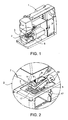
- FIG. 1 shows a partially cut-open sewing machine 1 with a connected thereto holding device 3 for a textile writer 5.
- the framed by a circular line 2 portion is in FIG. 2 shown enlarged.
- At the bottom of the machine head 7 protrudes one Needle bar 9, which is movable up and down by a needle bar drive in the vertical direction or in the direction of the needle bar axis 8.
- At the lower end of the needle bar 9 is a needle holder 11 for releasably securing a sewing needle 13 (FIG. Fig. 5 ) firmly connected to the needle bar 9.
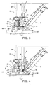
- FIG. 3 shows the arrangement FIG. 1 in a partially cutaway side view.
- the holding device 3 comprises a base part 19 with a Nähfussschaft 21 for attachment to the usually conically shaped lower end of a Nähfussstange 23.
- the base member 19 is connected analogously to a presser foot, for example by means of a fixing lever 25 fixed to the Nähfussstange 23.
- the base part 19 comprises a first guide pin 27.
- first guide pin 27 protrudes downwards parallel to the presser foot axis 24 into a corresponding first bore 29 on a first leg 15a of the tool holder 15 aligned parallel to the throat plate 17.
- a second guide pin 31 extends parallel to the first guide pin 27 upwards into a corresponding second bore (not visible) on the base part 19.
- the first Bore 29 and the second bore are formed as bearings for the respective guide pins 27, 31.
- other linear guide elements and correspondingly adapted bearings can be provided.
- a recess is formed on the base portion 19 which exposes the second bore in a central portion of the base portion 19 and exposes a lower abutment surface 33a and an upper abutment surface 33b on the base portion 19 adjacent to the second bore.
- a coil spring 35 between the lower stop surface 33a and a second guide pin 31 radially projecting limiting means, such as a Seegering 37, held with slight bias, that the Seeger ring 37 is present at the upper stop surface 33b.
- the spring constant or the force of Coil spring 35 is dimensioned so that it is able to raise the tool holder 15 with the tool held therein - in the present example, this is the textile writer 5 - quickly and reliably in the normal position.
- the holding device 3 is designed so that the movement of the needle bar 9 of the sewing machine 1, as it takes place during sewing, can be used to move the tool holder 15 with the tool mounted therein in the manner described.
- the tool holder 15 comprises a coupling device 39 which is designed and arranged such that the needle bar 9 or another transmission element 41 formed on the needle bar 9 or connected thereto can transmit kinetic energy to the tool holder 15.
- the transmission element 41 is the underside of the needle holder 11.
- the coupling device 39 is designed and arranged such that the transmission element 41 performs at least a portion of this movement cycle when performing an up-and-down movement of the needle bar 9, as in sewing 'Is coupled to the coupling device 39 and so is able to move the tool holder 15 according to the predetermined guidance.
- the coupling device 39 could be formed directly as part of the first leg 15a of the tool holder 15, wherein the extended needle bar axis 8 intersects this portion.
- the coupling device 39 comprises a shock absorber or an elastically resilient element, such as a spring, in order to damp or cushion the impacts of the needle bar 9 or of the transmission element 41 held thereon when it strikes the first leg 15a.
- a damping or spring member could alternatively also be formed on the side of the needle bar 9 or on the transmission element 41.
- Such a resilient element can also cause a spring-loaded or elastic pressing of the tool on the workpiece to be processed at the same time.
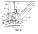
- the tool holder 15 includes adjacent to the first leg 15 a second leg 15 b.
- the two legs 15a, 15b enclose an angle of 90 ° + ⁇ , such that a textile scribe 5 fixed axially parallel to the second leg 15b is inclined at an inclination angle ⁇ with respect to the needle bar axis 8. It is assumed that the needle bar axis 8 is aligned vertically to the surface of the needle plate 17 and the sheet 44 or fabric lying thereon.
- the inclination angle ⁇ is greater than or equal to 0 °. It may for example be about 45 ° and is preferably in a range of about 30 ° to about 60 °.
- the position or orientation of the second leg 15b relative to the first leg 15a can fixed or alternatively-by means of a continuously or in stages adjustable adjustment (not shown) can be set.
- a tool holder 15 may also be designed so that the textile writer 5 or the tool in a basic position of the tool holder 15 rests passively on the sheet 44 or is pressed onto this, and is lifted by the action of the needle bar 9 from the fabric 44.
- the tool holder 15 can also be articulated permanently or releasably connected to the needle bar 9 and / or the Nähfussstange 23 (no representation).
- the tool holder 15 can also be designed to fasten any other tools, such as, for example, cutting knives, adhesive cartridges or a laser for material processing.
- any other tools such as, for example, cutting knives, adhesive cartridges or a laser for material processing.
- active tools such as lasers, motor-operated scissors and the like can thus be expressly used, which are supplied with energy, for example via a connection cable for sewing machine control, and optionally controlled by the sewing machine control.
- the tool holder 15 with the tool can preferably be arranged and aligned in any position relative to the base part 19.
- an adjusting device (not shown) is preferably provided, which allows, for example by means of an adjusting screw to adjust the height level of the pen tip 45 relative to the first leg 15a.
- the pressing force of the pen tip 45th be adjusted against the throat plate 17. If a fabric 44 lies on the stitch plate 17, the contact force of the writing tip 45 on the fabric 44 can be changed in an analogous manner and adapted to the thickness and type of the fabric 44.
- this can include, for example exchangeable inserts or adapter 47 and resilient clamping means 49.
- a cuff-shaped adapter 47 in the region of the pen tip 45 and resilient retaining clips are shown as clamping means 49 in the rear region of the second leg 15b.
- a stop is formed, which prevents the textile pin 5 can move axially during operation.
- the stop may also be designed to be resilient and / or adjustable in its position. As a result, an adaptation to different textile pins 5 is possible.
- FIG. 5 shows an arrangement according to FIG. 3
- the sewing needle 13 is a multiple sewing needle in which none of the individual sewing needles 13 is coaxial with the needle bar axis 8
- the writing tip 45 of the textile pen 5 may be as shown in FIG FIG. 5 represented without radial offset with respect to the extended needle bar axis 8 are arranged.
- the tool holder 15 or the adapter be designed or aligned so that the pen tip 45 with respect to the needle bar axis 8 has a radial offset, which may be of the order of, for example, about one millimeter to about 25mm and is optionally adjustable.
- the tool holder 15 or parts thereof such as e.g. one or more adapters 47 may also be designed to receive and fix other tools instead of textile pens 5 (not shown).
- a generated by the zigzag drive of the sewing machine 1 pivotal or pendulum motion of the needle bar 9 to a movement or other action of the to cause or influence the tool holder 15 held tool can be used in further embodiments of the invention.
- a tool may include not only passive elements but also active components, such as a laser light source for locally heating the sheet 44 or a piezoelectric vibrator for a cutting knife (not shown).
Abstract
Description
Gegenstand der Erfindung ist eine Haltevorrichtung für ein Werkzeug zur Bearbeitung eines textilen oder nicht textilen Flächengebildes bei einer Nähmaschine und ein Verfahren zum Bearbeiten des Flächengebildes mit dem Werkzeug gemäss den Merkmalen der Patentansprüche 1 und 9.The invention relates to a holding device for a tool for processing a textile or non-textile fabric in a sewing machine and a method for processing the sheet with the tool according to the features of the
Nähmaschinen und Stickmaschinen umfassen jeweils eine Stichbildungsvorrichtung zum Erstellen von Nähten oder Stickmustern in einem textilen Flächengebilde bzw. Nähgut. Dabei wird das Nähgut in einer Ebene unterhalb eines Maschinenkopfs relativ zu einer Nähnadel bewegt bzw. schrittweise verschoben. Die Nähnadel ist wieder lösbar mit einem am unteren Ende einer Nadelstange angeordneten Nadelhalter verbunden. Die Nadelstange ragt unten am Maschinenkopf hervor und ist von einem Nadelstangenantrieb in axialer Richtung auf- und abbewegbar, derart, dass die Nähnadel Nähstiche ausführen kann. In geringem Abstand ragt parallel zur Nadelstange eine Nähfussstange unten am Maschinenkopf hervor. Sie umfasst in der Regel ein konisch bzw. kegelartig zugespitztes unteres Ende zum Ankoppeln und Befestigen verschiedener Nähfüsse. Jeder der Nähfüsse umfasst einen mit dem konischen Ende der Nähfussstange korrespondierenden Schaft und kann so leicht von unten her auf die Nähfussstange aufgesetzt werden. Dabei wird der Nähfuss automatisch zentriert und gegebenenfalls durch weitere Ausrichtmittel in eine vorgegebene Solllage gebracht. Dort kann er z.B. mittels eines Haltebügels oder eines anderen Befestigungsmittels fixiert werden. Solche Nähfüsse sind in unterschiedlichen Ausführungsformen - je nach Art der auszuführenden Stiche - bekannt. Zum Nähen wird die Nähfussstange mit dem Nähfuss abgesenkt, derart, dass die Nähfusssohle auf dem Nähgut aufliegt. Die Nähfussstange wird durch die Kraft einer Feder nach unten gedrückt, sodass die Nähfusssohle federnd auf die Oberseite des Nähguts gedrückt wird. Die Nähnadel mit dem Oberfaden wird zumindest näherungsweise vertikal zur Nähgutebene in das Nähgut eingestochen und in entgegengesetzter Richtung wieder herausgezogen. Das Nähgut kann z.B. durch einen Transporteur vor der Ausführung des jeweils nächsten Nähstichs in die dafür erforderliche neue Position verschoben werden. Alternativ kann das Nähgut auch in einen Stickrahmen eingespannt sein. Mittels einer x-y-Bewegungsvorrichtung wird der Stickrahmen schrittweise verschoben, derart, dass jeweils die nächste Einstichstelle des Nähguts unter die Nähnadel zu liegen kommt. Die Bewegungen des Stickrahmens werden von der Nähmaschinensteuerung oder alternativ von einem PC bzw. von einer externen Steuerung kontrolliert und erfolgen koordiniert mit den Stichbewegungen der Nadelstange. Bei einer weiteren alternativen Anwendung, z.B. dem Stopfen oder Quilten, wird das Nähgut manuell in der Nähgutebene verschoben. Diese Techniken werden als hinlänglich bekannt vorausgesetzt.Sewing machines and embroidery machines each comprise a stitch forming device for creating seams or embroidery patterns in a textile fabric or sewing material. The sewing material is moved in a plane below a machine head relative to a sewing needle or moved stepwise. The suture needle is releasably connected to a needle holder located at the lower end of a needle bar. The needle bar protrudes at the bottom of the machine head and is movable up and down in the axial direction by a needle bar drive, such that the sewing needle can execute sewing stitches. At a small distance protrudes parallel to the needle bar a Nähfussstange down at the machine head. It usually comprises a conical or tapered tapered lower end for coupling and attaching various presser feet. Each of the presser feet includes one with the conical end of the presser foot bar corresponding shaft and can be easily placed from below on the Nähfussstange. In this case, the presser foot is automatically centered and optionally brought by further alignment in a predetermined desired position. There he can be fixed for example by means of a retaining clip or other fastener. Such presser feet are known in different embodiments - depending on the nature of the stitches to be executed. For sewing, the presser foot is lowered with the presser foot in such a way that the foot of the presser foot rests on the sewing material. The presser foot is pushed down by the force of a spring so that the foot of the presser foot is pressed resiliently onto the upper side of the sewing material. The sewing needle with the upper thread is at least approximately inserted vertically into the sewing material to the sewing material and pulled out in the opposite direction again. The sewing material can be moved, for example by a feed dog before the execution of the next stitch in the required new position. Alternatively, the fabric may also be clamped in an embroidery frame. By means of an xy-movement device of the embroidery frame is gradually shifted, so that in each case the next puncture site of the material comes to rest under the sewing needle. The movements of the hoop are controlled by the sewing machine control or alternatively by a PC or by an external control and are coordinated with the stitch movements of Needle bar. In a further alternative application, for example, the stuffing or quilting, the material is manually moved in the Nähgutebene. These techniques are presumed to be well known.
Es ist auch bekannt, anstelle von Nähnadeln andere Werkzeuge zum Bearbeiten des Nähguts zu verwenden. So kann beispielsweise anstelle einer Einfach- oder Mehrfachnähnadel eine Schneidnadel an der Nadelstange befestigt werden, welche zum Schneiden des Nähguts verwendet werden kann.It is also known to use other tools for processing the sewing material instead of sewing needles. Thus, for example, instead of a single or Mehrfachnähnadel a cutting needle are attached to the needle bar, which can be used to cut the material.
Aus der
Ein Nachteil dieser Methode liegt darin, dass diese Vorrichtung nur bei speziell ausgerüsteten Nähmaschinen eingesetzt werden kann. Zudem ist der Hub des Hüpfermechanismus relativ klein. Dies kann insbesondere bei dicken Stoffen oder bei mehreren Stofflagen zu Problemen führen.A disadvantage of this method is that this device can only be used with specially equipped sewing machines. In addition, the stroke of the Hüpfermechanismus is relatively small. This can lead to problems especially with thick fabrics or with several fabric layers.
Aus der
Eine Aufgabe der vorliegenden Erfindung ist es, eine verbesserte Vorrichtung und ein einfaches Verfahren zum Aufbringen von Farben auf ein Flächengebilde mittels beliebiger handelsüblicher Nähmaschinen zu schaffen. Eine weitere Aufgabe der Erfindung ist es, die Vorrichtung und das Verfahren derart auszubilden, dass zum Aufbringen der Farben bzw. zum Bedrucken des Flächengebildes handelsübliche Textilschreiber bzw. Schreibstifte benutzt werden können. Eine weitere Aufgabe der Erfindung besteht darin, die Vorrichtung und das Verfahren derart auszubilden, dass anstelle von Schreibstiften auch andere Bearbeitungswerkzeuge verwendet werden können, und dass anstelle des Aufbringens von Farbe - entsprechend der jeweils verwendeten Werkzeuge - das Flächengebilde auch in anderer Weise bearbeitet werden kann.An object of the present invention is to provide an improved apparatus and method for applying paint to a fabric using any commercially available sewing machine. A further object of the invention is to design the device and the method such that commercial textile pens or pens can be used to apply the colors or to print the fabric. A further object of the invention is to design the apparatus and method such that other processing tools can be used instead of pens, and that instead of applying paint - according to the particular tools used - the sheet can be processed in other ways ,
Diese Aufgaben werden gelöst durch eine Haltevorrichtung für ein Werkzeug und durch ein Verfahren zum Bearbeiten eines textilen oder nicht textilen Flächengebildes gemäss den Merkmalen der Ansprüche 1 und 9.These objects are achieved by a holding device for a tool and by a method for processing a textile or non-textile fabric according to the features of
Die erfindungsgemässe Haltevorrichtung wird analog zu einem handelsüblichen Nähfuss an der Nähfussstange der Nähmaschine befestigt. Die Haltevorrichtung umfasst einen Werkzeughalter zum Aufnehmen und Befestigen eines handelsüblichen Textilschreibers oder alternativ eines anderen Werkzeugs. Der Werkzeughalter ist an einem Basisteil schwenkbar oder in anderer Weise geführt bewegbar oder verschiebbar gehalten. Wenn die Haltevorrichtung an der Nähfussstange befestigt ist, gelangt die Nadelstange bzw. ein mit der Nadelstange verbundenes Übertragungsteil wie z.B. der Nadelhalter beim Absenken bzw. beim Ausführen einer Stichbewegung in Kontakt mit einem Kopplungselement am Werkzeughalter. Durch die Krafteinwirkung der Nadelstange bzw. des Übertragungsteils auf das Kopplungselement führt der Werkzeughalter mit dem Werkzeug eine Bewegung entsprechend des oder der durch die Führung vorgegebenen Bewegungsfreiheitsgrade aus. Vorzugsweise ist der Werkzeughalter derart federbelastet, dass er ohne zusätzliche Krafteinwirkung seitens der Nadelstange in einer Grundstellung am Basisteil gehalten ist bzw. in diese Grundstellung zurückkehrt, wenn die Krafteinwirkung der Nadelstange entfällt. Bei einer bevorzugten Ausgestaltung der Erfindung ist die Haltevorrichtung so ausgebildet, dass der Werkzeughalter entgegen der Federkraft einer Rückstellfeder um wenige Millimeter geführt parallel zur Nähfussachse nach unten verschoben wird, wenn das untere Ende der Nadelstange bzw. ein daran gehaltenes Übertragungselement wie z.B. ein Teil des Nadelhalters bei der Abwärtsbewegung kurz vor dem unteren Wendepunkt auf einen als Kopplungselement bezeichneten Bereich des Werkzeughalters auftrifft. Vorzugsweise umfasst das Übertragungselement einen Stossdämpfer oder ein elastisch federndes Element wie z.B. eine Feder, um die Schläge der Nadelstange zu dämpfen bzw. abzufedern. Zum Bewegen des Werkzeughalters und damit auch des daran befestigten Werkzeugs kann die Bewegung der Nadelstange genutzt werden, wie sie sonst bei einem herkömmlichen Näh- oder Stickvorgang vorgesehen ist. Alternativ oder zusätzlich zur Axialbewegung der Nadelstange könnte auch eine Schwenkbewegung der Nadelstange, wie sie herkömmlich bei Zick-Zack-Stichen verwendet wird, zur Bewegungsübertragung an den Werkzeughalter genutzt werden.The holding device according to the invention is attached to the sewing foot bar of the sewing machine analogously to a commercially available presser foot. The holding device comprises a tool holder for receiving and securing a commercial textile writer or alternatively another tool. The tool holder is pivotally or otherwise guided out movably or displaceably held on a base part. When the holding device is fastened to the presser foot rod, the needle bar or a transmission part connected to the needle bar, for example the needle holder, comes into contact with a coupling element on the tool holder during lowering or during a stitch movement. By the action of force of the needle bar or the transmission part on the coupling element of the tool holder with the tool performs a movement according to or predetermined by the guide movement degrees of freedom. Preferably, the tool holder is spring-loaded such that it is held without additional force by the needle bar in a basic position on the base part or returns to this basic position when the force of the needle bar is eliminated. In a preferred embodiment of the invention, the holding device is designed so that the tool holder against the spring force of a return spring by a few millimeters guided parallel to the Nähfussachse is shifted downwards, when the lower end of the needle bar or a transfer element held thereon such as a part of the needle holder during the downward movement shortly before the lower inflection point impinges on a designated coupling element region of the tool holder. Preferably, the transmission element comprises a shock absorber or an elastically resilient element, such as a spring, in order to damp or cushion the impacts of the needle bar. To move the tool holder and thus also the tool attached thereto, the movement of the needle bar can be used, as otherwise provided in a conventional sewing or embroidery process. Alternatively or in addition to the axial movement of the needle bar, a pivoting movement of the needle bar, as is conventionally used in zig-zag stitches, could also be used to transmit the motion to the tool holder.
Bei einer bevorzugten Ausgestaltung der Haltevorrichtung ist der Werkzeughalter zum Aufnehmen handelsüblicher Textilstifte ausgebildet. Er kann z.B. auswechselbare Adapter zum Fixieren solcher Stifte in einer definierten Lage umfassen, derart, dass die Schreibspitze im Schnittpunkt der Stiftachse und der Nadelstangenachse liegt und dass auf dem Nähgut anstelle von Einstichstellen der Nähnadel Farbpunkte des Textilschreibers ausgebildet werden. Alternativ können der Werkzeughalter bzw. die Adapter auch so ausgebildet sein, dass die Schreibspitze des Textilschreibers etwas radial versetzt zur verlängerten Nadelstangenachse angeordnet ist. In diesem Fall ist es möglich, selbst bei in den Nadelhalter eingesetzter Nähnadel parallel versetzt zu den Nähstichen Farbpunkte mit dem Textilschreiber auf dem Nähgut auszubilden. Der Werkzeughalter ist vorzugsweise so ausgebildet, dass die Achse des darin fixierten Textilschreibers geneigt zur Nadelstangenachse angeordnet ist. Auf diese Weise ist die Länge der verwendbaren Textilschreiber nicht durch den Abstand zwischen dem Maschinenkopf und dem Nähgut beschränkt. Bei Verwendung von Mehrfachnadeln oder bei radial versetzt bezüglich der Nadelstangenachse angeordneter Schreibspitze des Textilschreibers ist es möglich, simultan mit einem Näh- bzw. Stickvorgang ein Flächengebilde zu bedrucken. In diesem Fall bleibt die Nähnadel während des Bearbeitens des Flächengebildes in den Nadelhalter eingesetzt. Optional kann die Haltevorrichtung einen Justiermechanismus umfassen, der es erlaubt, den Bewegungsbereich des Werkzeughalters einzugrenzen. Mit dem Justiermechanismus können beispielsweise Begrenzungen für die Lagen der Grundstellung und/oder der Endstellung des Werkzeughalters in Bezug auf das Basisteil eingestellt werden. In diesem Fall kann der Justiermechanismus z.B. zur Anpassung der Höhenlage des Textilschreibers relativ zum zu bearbeitenden Flächengebilde verwendet werden. Allgemein kann die Justiervorrichtung Mittel zum Einstellen der gegenseitigen Lage zweier relativ zueinander bewegbaren Objekte umfassen, wobei mindestens eines dieser Objekte ein Element der Haltevorrichtung ist. Beispiele solcher Objektpaare sind Nähfussstange-Basisteil, Basisteil-Werkzeughalter, Werkzeughalter-Adapter (für Werkzeug); Werkzeughalter-Werkzeug.In a preferred embodiment of the holding device of the tool holder is designed for receiving commercially available textile pins. It may, for example, include interchangeable adapters for fixing such pins in a defined position, such that the writing tip lies at the intersection of the pin axis and the needle bar axis and that instead of puncturing sites of the sewing needle color points of the textile writer are formed on the fabric. Alternatively, the tool holder or the Adapter also be designed so that the writing tip of the textile writer is arranged slightly offset radially to the extended needle bar axis. In this case, it is possible to form color dots with the textile writer on the sewing material parallel to the sewing stitches even when the sewing needle is inserted into the needle holder. The tool holder is preferably designed such that the axis of the textile writer fixed therein is arranged inclined to the needle bar axis. In this way, the length of the usable textile writer is not limited by the distance between the machine head and the fabric. When using multiple needles or radially offset with respect to the needle bar axis arranged writing tip of the textile writer, it is possible to simultaneously print a fabric with a sewing or embroidery process. In this case, the sewing needle remains inserted into the needle holder during the processing of the fabric. Optionally, the holding device may comprise an adjusting mechanism, which allows to limit the range of movement of the tool holder. For example, limits for the positions of the basic position and / or the end position of the tool holder with respect to the base part can be set with the adjusting mechanism. In this case, the adjustment mechanism can be used, for example, for adjusting the height position of the textile writer relative to the sheet to be processed. In general, the adjusting device may comprise means for adjusting the mutual position of two relatively movable objects, wherein at least one of these objects is an element of the holding device. Examples of such pairs of objects are squeeze bar base, base part tool holder, tool holder adapter (for tool); Tool holder tool.
Die Haltevorrichtung oder ein Adapter zum Befestigen des Werkzeugs am Werkzeughalter können so ausgebildet sein, dass das Werkzeug in unterschiedlichen Lagen relativ zum Basisteil befestigt werden kann. So kann beispielsweise ein Textilschreiber mit unterschiedlichen Neigungswinkeln bezüglich der Nadelstangenachse mittels der Haltevorrichtung an die Nähmaschine angeschlossen werden. Ein wesentlicher Vorteil der Erfindung liegt darin, dass die Haltevorrichtung anstelle eines herkömmlichen Nähfusses an nahezu beliebige Nähmaschinen angeschlossen werden kann, und dass dafür in der Regel keine weiteren Anpassungen auf Seite der Nähmaschine erforderlich sind. Die Höhe bzw. Lage der Haltevorrichtung am Nähfuss kann fest vorgegeben oder alternativ einstellbar sein. Die Haltevorrichtung kann bei unterschiedlichen Konfigurationen einer Nähmaschine mit oder ohne aktivem Transporteur oder Stickrahmen genutzt werden. Zur Bearbeitung eines textilen Flächengebildes mit dem in der Haltevorrichtung gehaltenen Werkzeug können unterschiedliche Betriebsarten der Nähmaschine verwendet werden. Insbesondere kann das Werkzeug analog zu einem Nähvorgang mit zyklischen Bewegungen der Nadelstange betrieben werden. Das Flächengebilde kann dabei synchron zur Nadelstangenbewegung automatisch durch die jeweilige Transportvorrichtung oder manuell relativ zum Werkzeug verschoben werden. Die Nadelstange muss nicht zwingend zyklische Bewegungen ausführen. Sie kann z.B. temporär von der antreibenden Oberwelle entkoppelt oder durch entsprechende Steuerung der Oberwellenbewegung in vorgebbare Lagen gebracht werden. Insbesondere kann so ein Textilschreiber als Werkzeug durch eine halbe Umdrehung der Oberwelle in eine Arbeitsstellung abgesenkt werden. In dieser Arbeitsposition liegt die Schreibspitze auf dem Flächengebilde auf. Durch Verschieben des Flächengebildes können ausgezogene Linien auf dem Flächengebilde erstellt werden. Danach wird das Werkzeug durch eine weitere halbe Umdrehung der Oberwelle wieder in eine Ruhelage angehoben. Vorzugsweise ist die Steuerung so ausgebildet, dass die Bewegungen der Nadelstange und des Nähguts unabhängig voneinander kontrolliert werden können. Bei einer besonders bevorzugten Variante können auch die Bewegungsgeschwindigkeiten des Stickrahmens und/oder der Nadelstange von der Steuerung kontrolliert werden. Durch unterschiedliche Einwirkungszeiten des Textilschreibers auf das Flächengebilde kann das Erscheinungsbild der erzeugten Linien verändert werden. Durch ein sanftes und schonendes Aufsetzen der Schreiberspitze auf dem Flächengebilde kann die Fleckenbildung bei den Ansatzstellen von Linien verhindert werden. Zudem erhöht sich dadurch die Nutzungsdauer des Textilschreibers. Anhand einiger Figuren wird eine beispielhafte Ausführungsform der Erfindung im Folgenden näher beschrieben. Dabei zeigen
Figur 1- eine perspektivische Ansicht einer teilweise aufgeschnittenen Nähmaschine mit daran angeschlossener Haltevorrichtung für einen Textilschreiber,
Figur 2- ein in
Figur 1Kreis 2 umrahmtes Detail der Nähmaschine im Bereich der Haltevorrichtung mit dem Textilschreiber, Figur 3- eine Seitenansicht der Anordnung aus
Figur 1 im Bereich der Haltevorrichtung in einer ersten Betriebsstellung, - Figur 4
- die
Anordnung aus Figur 3 , jedoch in einer zweiten Betriebsstellung, Figur 5- die
Anordnung aus Figur 3 , jedoch mit an die Nadelstange angeschlossener Nähnadel.
- FIG. 1
- a perspective view of a partially cut sewing machine with attached holding device for a textile writer,
- FIG. 2
- a in
FIG. 1 with acircle 2 framed detail of the sewing machine in the area of the holding device with the textile writer, - FIG. 3
- a side view of the arrangement
FIG. 1 in the region of the holding device in a first operating position, - FIG. 4
- the arrangement
FIG. 3 but in a second operating position, - FIG. 5
- the arrangement
FIG. 3 , but with sewing needle connected to the needle bar.
Der Werkzeughalter 15 umfasst angrenzend an den ersten Schenkel 15a einen zweiten Schenkel 15b. Die beiden Schenkel 15a, 15b schliessen einen Winkel 90°+α ein, derart, dass ein am zweiten Schenkel 15b achsparallel fixierter Textilschreiber 5 unter einem Neigungswinkel α bezüglich der Nadelstangenachse 8 geneigt ist. Dabei wird vorausgesetzt, dass die Nadelstangenachse 8 vertikal zur Oberfläche der Stichplatte 17 bzw. zum darauf aufliegenden Flächengebilde 44 bzw. Nähgut ausgerichtet ist. Der Neigungswinkel α ist grösser oder gleich 0°. Er kann z.B. etwa 45° betragen und liegt vorzugsweise in einem Bereich von etwa 30° bis etwa 60°. Die Lage bzw. Orientierung des zweiten Schenkels 15b relativ zum ersten Schenkel 15a kann fest vorgegeben oder alternativ-mittels eines kontinuierlich oder in Stufen verstellbaren Einstellmittels (nicht dargestellt) eingestellt werden. Alternativ kann ein Werkzeughalter 15 auch so ausgebildet sein, dass der Textilschreiber 5 bzw. das Werkzeug in einer Grundstellung des Werkzeughalters 15 passiv auf dem Flächengebilde 44 aufliegt oder auf dieses aufgedrückt wird, und durch die Einwirkung der Nadelstange 9 vom Flächengebilde 44 abgehoben wird. Nach dem Entkoppeln der Nadelstange 9 vom Werkzeughalter 15 (z.B. durch Schwenken der Nadelstange 9 mittels des Zick-Zack-Antriebs in eine Ausrichtung, bei der das Übertragungselement 41 nicht mehr auf das Kopplungselement 39 einwirken kann oder alternativ durch Stoppen der Nadelstangenbewegung) wird der Textilschreiber 5 solange nicht mehr vom Flächengebilde 44 abgehoben, bis die Kopplung mit der Nadelstange 9 wieder hergestellt wird. Auf diese Weise kann das Werkzeug kontinuierlich auf das Flächengebilde 44 einwirken. Mit einem Textilschreiber 5 können so nebst Punktbildern auch Bilder mit ausgezogenen Linien erstellt werden.The
Bei einer weiteren alternativen Ausgestaltung der Erfindung kann der Werkzeughalter 15 auch gelenkig permanent oder wieder lösbar mit der Nadelstange 9 und/oder der Nähfussstange 23 verbunden sein (keine Darstellung).In a further alternative embodiment of the invention, the
Bei weiteren alternativen Ausgestaltungen der Erfindung kann der Werkzeughalter 15 auch zum Befestigen beliebiger anderer Werkzeuge wie z.B. Schneidmessern, Klebstoffpatronen oder eines Lasers für die Materialbearbeitung ausgebildet sein. Nebst passiven Werkzeugen können somit ausdrücklich auch aktive Werkzeuge wie Laser, motorisch betriebene.Scheren und dergleichen genutzt werden, welche z.B. über ein Verbindungskabel zur Nähmaschinensteuerung mit Energie versorgt und gegebenenfalls von der Nähmaschinensteuerung kontrolliert werden. Der Werkzeughalter 15 mit dem Werkzeug kann vorzugsweise in beliebigen Lagen relativ zum Basisteil 19 angeordnet und ausgerichtet werden.In further alternative embodiments of the invention For example, the
Beim vorliegenden Beispiel einer Haltevorrichtung 3 für einen Textilschreiber 5 ist vorzugsweise eine Justiereinrichtung (nicht dargestellt) vorgesehen, welche es erlaubt, z.B. mittels einer Justierschraube das Höhenniveau der Schreiberspitze 45 relativ zum ersten Schenkel 15a einzustellen. Damit kann in der Grundstellung des Werkzeughalters der Abstand H = H1 oder bei voll abgesenkter Nadelstange 9 der Abstand H = H2 zwischen der Schreiberspitze 45 und der Stichplatte 17 vorgegeben werden. Bei voll abgesenkter Nadelstange 9 - dies entspricht einer zweiten Arbeitsstellung und ist in
Zum Ausrichten und Fixieren unterschiedlicher Textilstifte 5 in einer definierten Lage am Werkzeughalter 15 kann dieser z.B. austauschbare Einsätze oder Adapter 47 und federnde Klemmmittel 49 umfassen. In
Bei alternativen Ausgestaltungen der Erfindung kann der Werkzeughalter 15 oder Teile davon wie z.B. ein oder mehrere Adapter 47 auch zum Aufnehmen und Fixieren anderer Werkzeuge anstelle von Textilschreibern 5 ausgebildet sein (keine Darstellung). Anstelle oder zusätzlich zur vertikalen Auf-Ab-Bewegung der Nadelstange 9 kann bei weiteren Ausgestaltungen der Erfindung auch eine durch den Zick-Zack-Antrieb der Nähmaschine 1 generierbare Schwenk- oder Pendelbewegung der Nadelstange 9 dazu genutzt werden, eine Bewegung oder eine andere Aktion des am Werkzeughalter 15 gehaltenen Werkzeugs zu veranlassen oder zu beeinflussen. Insbesondere kann ein Werkzeug nicht nur passive Elemente, sondern auch aktive Komponenten umfassen, beispielsweise eine Laserlichtquelle zum lokalen Erhitzen des Flächengebildes 44 oder einen piezoelektrischen Schwingungserzeuger für ein Schneidemesser (keine Darstellung).In alternative embodiments of the invention, the
Claims (10)
- A holding device (3) for a tool for processing a textile or non-textile sheet material (44) for a sewing machine (1), wherein a presser foot shaft (21) for attaching the holding device (3) to a presser foot bar (23) of the sewing machine (1) is formed on a base part (19), a tool holder (15) configured for receiving the tool is held on the base part (19), and the tool holder (15) comprises a coupling device (39) for controlling by a transmission element (11) configured on the needle bar (9).
- A holding device (3) according to claim 1, wherein the tool holder (15) is configured for receiving and/or holding standard commercial textile markers (5).
- A holding device (3) according to either of claims 1 or 2, wherein the tool holder (15) is held so as to be able to move on the base part (19), and the coupling device (39) is arranged and aligned on the tool holder (15) such that when the holding device (3) is mounted on the presser foot bar (23) of the sewing machine (1) it can be moved by the motion of the needle bar (9).
- A holding device (3) according to any one of claims 1 to 3, wherein the coupling device (39) comprises a shock absorber or elastically springing element.
- A holding device (3) according to any one of claims 1 to 4, wherein the tool holder (15) comprises a first leg (15a) and a second leg (15b), the first leg (15a) is moveably mounted on the base part (19) and the second leg (15b) is connected to the first leg (15a) so as to include a fixed or adjustable angle of inclination (90° + α).
- A holding device (3) according to claim 5, wherein the second leg (15b) comprises means for the detachable fixing of the tool in a predetermined position.
- A holding device (3) according to claim 6, wherein the means for predetermining the position of the tool comprise interchangeable adapters (47).
- A holding device according to any one of claims 1 to 7, wherein an adjusting mechanism is provided for limiting a range of movement and/or for controlling a relative position.
- A holding device (3) according to any one of claims 1 to 8, wherein a guide peg (27, 31) or other appropriate linear guiding element is configured on the base part (19) and/or on the tool holder (15) in such a way that when the holding device (3) is connected to the presser foot bar (23) of the sewing machine (1) the tool holder (15) is carried displaceably on the base part (19) parallel to the presser foot axis (24), and the tool holder (15) is held in a basic position or in a first working position on the base part (19) by the force of a spring without the action of any other forces.
- A method for processing a textile or non-textile sheet material (44) with a tool, wherein the tool is fixed to the presser foot bar (23) by means of a holding device (3) according to any one of claims 1 to 9, and is moved or its activity changed by the effect of the presser foot motion.
Applications Claiming Priority (1)
| Application Number | Priority Date | Filing Date | Title |
|---|---|---|---|
| CH00204/09A CH700377A1 (en) | 2009-02-11 | 2009-02-11 | Holding device for a tool for machining a textile or non-textile fabric in a sewing machine. |
Publications (2)
| Publication Number | Publication Date |
|---|---|
| EP2221409A1 EP2221409A1 (en) | 2010-08-25 |
| EP2221409B1 true EP2221409B1 (en) | 2012-03-21 |
Family
ID=42236340
Family Applications (1)
| Application Number | Title | Priority Date | Filing Date |
|---|---|---|---|
| EP10405007A Active EP2221409B1 (en) | 2009-02-11 | 2010-01-18 | Holding device for a tool for processing a textile or non-textile sheet for a sewing machine |
Country Status (7)
| Country | Link |
|---|---|
| US (1) | US8281726B2 (en) |
| EP (1) | EP2221409B1 (en) |
| JP (1) | JP5586246B2 (en) |
| CN (1) | CN101798731A (en) |
| AT (1) | ATE550470T1 (en) |
| CH (1) | CH700377A1 (en) |
| TW (1) | TW201037117A (en) |
Families Citing this family (8)
| Publication number | Priority date | Publication date | Assignee | Title |
|---|---|---|---|---|
| CH706492A1 (en) | 2012-05-09 | 2013-11-15 | Bernina Int Ag | Apparatus and method for punching a sheet with a sewing machine. |
| ES2718375T3 (en) * | 2013-11-14 | 2019-07-01 | Alberto Landoni | Multi-needle quilting machine and a corresponding quilting method |
| JP2015149991A (en) | 2014-02-10 | 2015-08-24 | ブラザー工業株式会社 | sewing machine |
| JP2015149992A (en) * | 2014-02-10 | 2015-08-24 | ブラザー工業株式会社 | sewing machine |
| JP6783988B2 (en) * | 2017-03-23 | 2020-11-11 | 豊田合成株式会社 | Reinforcing liquid application device for airbags |
| CN113201866B (en) * | 2021-05-19 | 2022-07-29 | 安徽戴家工艺有限公司 | Automatic sewing device for cushion of hanging chair |
| CN114436052A (en) * | 2022-01-21 | 2022-05-06 | 海洋石油工程股份有限公司 | Non-return device for hose recovery |
| CN117822217A (en) * | 2024-02-26 | 2024-04-05 | 江苏荣冠纺织科技有限公司 | Positioning device for sewing clothing |
Family Cites Families (21)
| Publication number | Priority date | Publication date | Assignee | Title |
|---|---|---|---|---|
| US223107A (en) * | 1879-12-30 | Improvement in tuck-markers for sewing-machines | ||
| US947506A (en) * | 1909-06-14 | 1910-01-25 | Isidor Weinbach | Combination pressure-foot and trimming attachment for sewing-machines. |
| US2511275A (en) * | 1948-11-10 | 1950-06-13 | Aune E Leino | Attachment for sewing machines for repairing hosiery |
| DE2544165C3 (en) * | 1975-10-03 | 1978-08-10 | Pfaff Industriemaschinen Gmbh, 6750 Kaiserslautern | Equipment on sewing machines for prepunching the sewing material |
| JPS5334455U (en) * | 1976-08-31 | 1978-03-25 | ||
| JPH0673579B2 (en) * | 1984-06-19 | 1994-09-21 | 蛇の目ミシン工業株式会社 | Sewing machine pen writing device |
| DE3902333A1 (en) * | 1989-01-27 | 1990-08-09 | Union Special Gmbh | METHOD FOR DETECTING A POSITION OF A SEWING MATERIAL ON A CONTROLLED DRIVING MACHINE, AND DEVICE FOR CARRYING OUT THE METHOD |
| JPH07133575A (en) * | 1991-02-28 | 1995-05-23 | Janome Sewing Mach Co Ltd | Sewing machine with embroidery function having pointillistic device |
| JPH05261187A (en) * | 1991-03-04 | 1993-10-12 | Janome Sewing Mach Co Ltd | Sewing machine having embroidering function and mark cutter device |
| JPH05317546A (en) * | 1991-03-25 | 1993-12-03 | Janome Sewing Mach Co Ltd | Sewing machine with embroidery function provided with embroidery pattern plotting function |
| JP3370129B2 (en) * | 1993-03-01 | 2003-01-27 | 株式会社バルダン | Loop seam forming device |
| JP3420648B2 (en) * | 1994-12-19 | 2003-06-30 | 株式会社バルダン | Sewing machine with coding function |
| JP3519034B2 (en) * | 2000-01-24 | 2004-04-12 | 株式会社タチエス | Sewing device for trim cover of vehicle seat |
| JP2002233682A (en) * | 2001-02-09 | 2002-08-20 | Kyowa:Kk | Pen for sewing machine |
| CN1633928A (en) * | 2003-12-31 | 2005-07-06 | 程旭辉 | Method and apparatus for automatic making garment templet and bushing plate |
| JP2007222188A (en) * | 2004-03-29 | 2007-09-06 | Tokai Ind Sewing Mach Co Ltd | Sequin feeder |
| JP2006110074A (en) * | 2004-10-14 | 2006-04-27 | Barudan Co Ltd | Sequin feeder |
| JP5091601B2 (en) * | 2006-10-13 | 2012-12-05 | 東海工業ミシン株式会社 | Sequin feeder and sewing machine capable of sequin sewing |
| JP2008200311A (en) * | 2007-02-21 | 2008-09-04 | Brother Ind Ltd | Sewing machine and sewing machine control program |
| JP2008220559A (en) * | 2007-03-12 | 2008-09-25 | Barudan Co Ltd | Multi-needle embroidery machine |
| DE502009000498D1 (en) * | 2008-09-04 | 2011-05-12 | Bernina Int Ag | Apparatus and method for cutting textile and non-textile fabrics |
-
2009
- 2009-02-11 CH CH00204/09A patent/CH700377A1/en not_active Application Discontinuation
-
2010
- 2010-01-18 AT AT10405007T patent/ATE550470T1/en active
- 2010-01-18 EP EP10405007A patent/EP2221409B1/en active Active
- 2010-01-22 JP JP2010011728A patent/JP5586246B2/en active Active
- 2010-02-05 TW TW099103420A patent/TW201037117A/en unknown
- 2010-02-05 CN CN201010113846A patent/CN101798731A/en active Pending
- 2010-02-05 US US12/700,789 patent/US8281726B2/en active Active
Also Published As
| Publication number | Publication date |
|---|---|
| CN101798731A (en) | 2010-08-11 |
| JP5586246B2 (en) | 2014-09-10 |
| US20100199900A1 (en) | 2010-08-12 |
| EP2221409A1 (en) | 2010-08-25 |
| TW201037117A (en) | 2010-10-16 |
| US8281726B2 (en) | 2012-10-09 |
| ATE550470T1 (en) | 2012-04-15 |
| CH700377A1 (en) | 2010-08-13 |
| JP2010185165A (en) | 2010-08-26 |
Similar Documents
| Publication | Publication Date | Title |
|---|---|---|
| EP2221409B1 (en) | Holding device for a tool for processing a textile or non-textile sheet for a sewing machine | |
| DE19820646B4 (en) | Pusher foot device for a sewing machine | |
| EP2662483B1 (en) | Device and process for stamping a fabric sheet of a sewing machine | |
| DE10116171A1 (en) | Surgical sewing machine | |
| DE102009004217A1 (en) | Two-needle sewing machine | |
| DE102012008091A1 (en) | Heat cutting device for embroidery machine | |
| EP2381023B1 (en) | Multi-needle sewing machine and method for operating same | |
| DE19916660C1 (en) | Buttonhole sewing machine has a control unit which determines the operation of the drives for cutting and stitching buttonholes of different shapes and/or sizes without manual resetting | |
| DE102009004218A1 (en) | Thread cutting device for a sewing machine | |
| DE102009004219A1 (en) | Switchable needle bar drive device | |
| DE3033152A1 (en) | WORKPIECE CUTTING DEVICE FOR SEWING MACHINES | |
| DE2935763A1 (en) | DEVICE FOR PRODUCING SEAM PICTURES CONSTRUCTED FROM STITCH GROUPS | |
| DE102014105494B4 (en) | Material pressing mechanism | |
| DE2038505A1 (en) | Missing stitch mechanism for sewing machines | |
| DE102006046362A1 (en) | Clamping foot device for edge sewing machine, includes foot holding mechanism with device for switching the foot between positions for single- and double-edge sewing | |
| DE291197C (en) | ||
| DE3420763A1 (en) | Process and apparatus for the selective embroidering and/or engraving and/or painting and/or perforating of material webs or blanks consisting of materials permeable or impermeable to needles and drills | |
| DE102008053780B4 (en) | edging machine | |
| DE10125108B4 (en) | Multi-needle chain stitch sewing machine and method for forming a sewing pattern in a fabric | |
| EP1559823B1 (en) | Eyelet buttonholing sewing machine | |
| DE10342433B4 (en) | Button-hole sewing machine has template which has to-be-processed object positioning edge and made of plastic, arranged at predetermined position at bearing plate by pins of bearing plate inserted into concave portions of template | |
| DE102009004220A1 (en) | Thread cutting device | |
| DE1931088A1 (en) | Buttonhole mechanism for household zigzag sewing machines | |
| DE202011103579U1 (en) | Embroidery machine with replaceable cutting tool | |
| EP2360305B1 (en) | Method for operating a sewing machine and sewing machine |
Legal Events
| Date | Code | Title | Description |
|---|---|---|---|
| PUAI | Public reference made under article 153(3) epc to a published international application that has entered the european phase |
Free format text: ORIGINAL CODE: 0009012 |
|
| AK | Designated contracting states |
Kind code of ref document: A1 Designated state(s): AT BE BG CH CY CZ DE DK EE ES FI FR GB GR HR HU IE IS IT LI LT LU LV MC MK MT NL NO PL PT RO SE SI SK SM TR |
|
| AX | Request for extension of the european patent |
Extension state: AL BA RS |
|
| 17P | Request for examination filed |
Effective date: 20110209 |
|
| RIC1 | Information provided on ipc code assigned before grant |
Ipc: D05C 13/00 20060101ALI20110831BHEP Ipc: D05B 35/00 20060101AFI20110831BHEP |
|
| GRAP | Despatch of communication of intention to grant a patent |
Free format text: ORIGINAL CODE: EPIDOSNIGR1 |
|
| GRAS | Grant fee paid |
Free format text: ORIGINAL CODE: EPIDOSNIGR3 |
|
| GRAA | (expected) grant |
Free format text: ORIGINAL CODE: 0009210 |
|
| AK | Designated contracting states |
Kind code of ref document: B1 Designated state(s): AT BE BG CH CY CZ DE DK EE ES FI FR GB GR HR HU IE IS IT LI LT LU LV MC MK MT NL NO PL PT RO SE SI SK SM TR |
|
| REG | Reference to a national code |
Ref country code: GB Ref legal event code: FG4D Free format text: NOT ENGLISH |
|
| REG | Reference to a national code |
Ref country code: CH Ref legal event code: EP Ref country code: CH Ref legal event code: NV Representative=s name: GACHNANG AG PATENTANWAELTE |
|
| REG | Reference to a national code |
Ref country code: IE Ref legal event code: FG4D Free format text: LANGUAGE OF EP DOCUMENT: GERMAN |
|
| REG | Reference to a national code |
Ref country code: AT Ref legal event code: REF Ref document number: 550470 Country of ref document: AT Kind code of ref document: T Effective date: 20120415 |
|
| RIN2 | Information on inventor provided after grant (corrected) |
Inventor name: BRUNNER, SEVERIN Inventor name: MUELLER, MARKUS Inventor name: DUNJIC, DUSAN |
|
| REG | Reference to a national code |
Ref country code: DE Ref legal event code: R096 Ref document number: 502010000546 Country of ref document: DE Effective date: 20120516 |
|
| REG | Reference to a national code |
Ref country code: NL Ref legal event code: VDEP Effective date: 20120321 |
|
| PG25 | Lapsed in a contracting state [announced via postgrant information from national office to epo] |
Ref country code: NO Free format text: LAPSE BECAUSE OF FAILURE TO SUBMIT A TRANSLATION OF THE DESCRIPTION OR TO PAY THE FEE WITHIN THE PRESCRIBED TIME-LIMIT Effective date: 20120621 Ref country code: LT Free format text: LAPSE BECAUSE OF FAILURE TO SUBMIT A TRANSLATION OF THE DESCRIPTION OR TO PAY THE FEE WITHIN THE PRESCRIBED TIME-LIMIT Effective date: 20120321 Ref country code: HR Free format text: LAPSE BECAUSE OF FAILURE TO SUBMIT A TRANSLATION OF THE DESCRIPTION OR TO PAY THE FEE WITHIN THE PRESCRIBED TIME-LIMIT Effective date: 20120321 |
|
| LTIE | Lt: invalidation of european patent or patent extension |
Effective date: 20120321 |
|
| PG25 | Lapsed in a contracting state [announced via postgrant information from national office to epo] |
Ref country code: FI Free format text: LAPSE BECAUSE OF FAILURE TO SUBMIT A TRANSLATION OF THE DESCRIPTION OR TO PAY THE FEE WITHIN THE PRESCRIBED TIME-LIMIT Effective date: 20120321 Ref country code: LV Free format text: LAPSE BECAUSE OF FAILURE TO SUBMIT A TRANSLATION OF THE DESCRIPTION OR TO PAY THE FEE WITHIN THE PRESCRIBED TIME-LIMIT Effective date: 20120321 Ref country code: GR Free format text: LAPSE BECAUSE OF FAILURE TO SUBMIT A TRANSLATION OF THE DESCRIPTION OR TO PAY THE FEE WITHIN THE PRESCRIBED TIME-LIMIT Effective date: 20120622 |
|
| PG25 | Lapsed in a contracting state [announced via postgrant information from national office to epo] |
Ref country code: CY Free format text: LAPSE BECAUSE OF FAILURE TO SUBMIT A TRANSLATION OF THE DESCRIPTION OR TO PAY THE FEE WITHIN THE PRESCRIBED TIME-LIMIT Effective date: 20120321 |
|
| PG25 | Lapsed in a contracting state [announced via postgrant information from national office to epo] |
Ref country code: EE Free format text: LAPSE BECAUSE OF FAILURE TO SUBMIT A TRANSLATION OF THE DESCRIPTION OR TO PAY THE FEE WITHIN THE PRESCRIBED TIME-LIMIT Effective date: 20120321 Ref country code: RO Free format text: LAPSE BECAUSE OF FAILURE TO SUBMIT A TRANSLATION OF THE DESCRIPTION OR TO PAY THE FEE WITHIN THE PRESCRIBED TIME-LIMIT Effective date: 20120321 Ref country code: CZ Free format text: LAPSE BECAUSE OF FAILURE TO SUBMIT A TRANSLATION OF THE DESCRIPTION OR TO PAY THE FEE WITHIN THE PRESCRIBED TIME-LIMIT Effective date: 20120321 Ref country code: SE Free format text: LAPSE BECAUSE OF FAILURE TO SUBMIT A TRANSLATION OF THE DESCRIPTION OR TO PAY THE FEE WITHIN THE PRESCRIBED TIME-LIMIT Effective date: 20120321 Ref country code: PL Free format text: LAPSE BECAUSE OF FAILURE TO SUBMIT A TRANSLATION OF THE DESCRIPTION OR TO PAY THE FEE WITHIN THE PRESCRIBED TIME-LIMIT Effective date: 20120321 Ref country code: SI Free format text: LAPSE BECAUSE OF FAILURE TO SUBMIT A TRANSLATION OF THE DESCRIPTION OR TO PAY THE FEE WITHIN THE PRESCRIBED TIME-LIMIT Effective date: 20120321 Ref country code: IS Free format text: LAPSE BECAUSE OF FAILURE TO SUBMIT A TRANSLATION OF THE DESCRIPTION OR TO PAY THE FEE WITHIN THE PRESCRIBED TIME-LIMIT Effective date: 20120721 |
|
| PG25 | Lapsed in a contracting state [announced via postgrant information from national office to epo] |
Ref country code: SK Free format text: LAPSE BECAUSE OF FAILURE TO SUBMIT A TRANSLATION OF THE DESCRIPTION OR TO PAY THE FEE WITHIN THE PRESCRIBED TIME-LIMIT Effective date: 20120321 Ref country code: PT Free format text: LAPSE BECAUSE OF FAILURE TO SUBMIT A TRANSLATION OF THE DESCRIPTION OR TO PAY THE FEE WITHIN THE PRESCRIBED TIME-LIMIT Effective date: 20120723 |
|
| PLBE | No opposition filed within time limit |
Free format text: ORIGINAL CODE: 0009261 |
|
| STAA | Information on the status of an ep patent application or granted ep patent |
Free format text: STATUS: NO OPPOSITION FILED WITHIN TIME LIMIT |
|
| PG25 | Lapsed in a contracting state [announced via postgrant information from national office to epo] |
Ref country code: NL Free format text: LAPSE BECAUSE OF FAILURE TO SUBMIT A TRANSLATION OF THE DESCRIPTION OR TO PAY THE FEE WITHIN THE PRESCRIBED TIME-LIMIT Effective date: 20120321 Ref country code: DK Free format text: LAPSE BECAUSE OF FAILURE TO SUBMIT A TRANSLATION OF THE DESCRIPTION OR TO PAY THE FEE WITHIN THE PRESCRIBED TIME-LIMIT Effective date: 20120321 |
|
| 26N | No opposition filed |
Effective date: 20130102 |
|
| PG25 | Lapsed in a contracting state [announced via postgrant information from national office to epo] |
Ref country code: IT Free format text: LAPSE BECAUSE OF FAILURE TO SUBMIT A TRANSLATION OF THE DESCRIPTION OR TO PAY THE FEE WITHIN THE PRESCRIBED TIME-LIMIT Effective date: 20120321 |
|
| REG | Reference to a national code |
Ref country code: DE Ref legal event code: R097 Ref document number: 502010000546 Country of ref document: DE Effective date: 20130102 |
|
| PG25 | Lapsed in a contracting state [announced via postgrant information from national office to epo] |
Ref country code: ES Free format text: LAPSE BECAUSE OF FAILURE TO SUBMIT A TRANSLATION OF THE DESCRIPTION OR TO PAY THE FEE WITHIN THE PRESCRIBED TIME-LIMIT Effective date: 20120702 |
|
| BERE | Be: lapsed |
Owner name: BERNINA INTERNATIONAL A.G. Effective date: 20130131 |
|
| PG25 | Lapsed in a contracting state [announced via postgrant information from national office to epo] |
Ref country code: BG Free format text: LAPSE BECAUSE OF FAILURE TO SUBMIT A TRANSLATION OF THE DESCRIPTION OR TO PAY THE FEE WITHIN THE PRESCRIBED TIME-LIMIT Effective date: 20120621 |
|
| PG25 | Lapsed in a contracting state [announced via postgrant information from national office to epo] |
Ref country code: MC Free format text: LAPSE BECAUSE OF NON-PAYMENT OF DUE FEES Effective date: 20130131 |
|
| REG | Reference to a national code |
Ref country code: IE Ref legal event code: MM4A |
|
| REG | Reference to a national code |
Ref country code: FR Ref legal event code: ST Effective date: 20130930 |
|
| PG25 | Lapsed in a contracting state [announced via postgrant information from national office to epo] |
Ref country code: BE Free format text: LAPSE BECAUSE OF NON-PAYMENT OF DUE FEES Effective date: 20130131 |
|
| PG25 | Lapsed in a contracting state [announced via postgrant information from national office to epo] |
Ref country code: FR Free format text: LAPSE BECAUSE OF NON-PAYMENT OF DUE FEES Effective date: 20130131 |
|
| PG25 | Lapsed in a contracting state [announced via postgrant information from national office to epo] |
Ref country code: IE Free format text: LAPSE BECAUSE OF NON-PAYMENT OF DUE FEES Effective date: 20130118 |
|
| PG25 | Lapsed in a contracting state [announced via postgrant information from national office to epo] |
Ref country code: MT Free format text: LAPSE BECAUSE OF FAILURE TO SUBMIT A TRANSLATION OF THE DESCRIPTION OR TO PAY THE FEE WITHIN THE PRESCRIBED TIME-LIMIT Effective date: 20120321 |
|
| PG25 | Lapsed in a contracting state [announced via postgrant information from national office to epo] |
Ref country code: SM Free format text: LAPSE BECAUSE OF FAILURE TO SUBMIT A TRANSLATION OF THE DESCRIPTION OR TO PAY THE FEE WITHIN THE PRESCRIBED TIME-LIMIT Effective date: 20120321 |
|
| PG25 | Lapsed in a contracting state [announced via postgrant information from national office to epo] |
Ref country code: TR Free format text: LAPSE BECAUSE OF FAILURE TO SUBMIT A TRANSLATION OF THE DESCRIPTION OR TO PAY THE FEE WITHIN THE PRESCRIBED TIME-LIMIT Effective date: 20120321 |
|
| PG25 | Lapsed in a contracting state [announced via postgrant information from national office to epo] |
Ref country code: LU Free format text: LAPSE BECAUSE OF NON-PAYMENT OF DUE FEES Effective date: 20130118 Ref country code: MK Free format text: LAPSE BECAUSE OF FAILURE TO SUBMIT A TRANSLATION OF THE DESCRIPTION OR TO PAY THE FEE WITHIN THE PRESCRIBED TIME-LIMIT Effective date: 20120321 Ref country code: HU Free format text: LAPSE BECAUSE OF FAILURE TO SUBMIT A TRANSLATION OF THE DESCRIPTION OR TO PAY THE FEE WITHIN THE PRESCRIBED TIME-LIMIT; INVALID AB INITIO Effective date: 20100118 |
|
| REG | Reference to a national code |
Ref country code: AT Ref legal event code: MM01 Ref document number: 550470 Country of ref document: AT Kind code of ref document: T Effective date: 20150118 |
|
| PG25 | Lapsed in a contracting state [announced via postgrant information from national office to epo] |
Ref country code: AT Free format text: LAPSE BECAUSE OF NON-PAYMENT OF DUE FEES Effective date: 20150118 |
|
| PGFP | Annual fee paid to national office [announced via postgrant information from national office to epo] |
Ref country code: CH Payment date: 20230125 Year of fee payment: 14 |
|
| PGFP | Annual fee paid to national office [announced via postgrant information from national office to epo] |
Ref country code: GB Payment date: 20230124 Year of fee payment: 14 Ref country code: DE Payment date: 20230127 Year of fee payment: 14 |