CN101798731A - Holding unit with the instrument of Sewing machines converted goods or non-woven - Google Patents
Holding unit with the instrument of Sewing machines converted goods or non-woven Download PDFInfo
- Publication number
- CN101798731A CN101798731A CN201010113846A CN201010113846A CN101798731A CN 101798731 A CN101798731 A CN 101798731A CN 201010113846 A CN201010113846 A CN 201010113846A CN 201010113846 A CN201010113846 A CN 201010113846A CN 101798731 A CN101798731 A CN 101798731A
- Authority
- CN
- China
- Prior art keywords
- instrument
- holding unit
- shank
- fabric
- folder
- Prior art date
- Legal status (The legal status is an assumption and is not a legal conclusion. Google has not performed a legal analysis and makes no representation as to the accuracy of the status listed.)
- Pending
Links
Images


Classifications
-
- D—TEXTILES; PAPER
- D05—SEWING; EMBROIDERING; TUFTING
- D05C—EMBROIDERING; TUFTING
- D05C13/00—Auxiliary devices incorporated in embroidering machines, not otherwise provided for; Ancillary apparatus for use with embroidering machines
-
- D—TEXTILES; PAPER
- D05—SEWING; EMBROIDERING; TUFTING
- D05B—SEWING
- D05B35/00—Work-feeding or -handling elements not otherwise provided for
Abstract
The present invention relates to a kind of holding unit of the instrument with Sewing machines converted goods or non-woven.Utilize the instrument of holding unit (3) with converted goods or non-woven (44) usefulness, for example fabric paintbrush (5) is fixed on the presser bar (23) of Sewing machines (1).This instrument is placed on the base (19) of holding unit (3) in a movable manner via instrument folder (15), and can be via the position or the action of the mobile change instrument of the shank (9) of Sewing machines (1).
Description
Technical field
The present invention relates to a kind of holding unit that comprises the 1st and the 9th feature of technical scheme that has with the instrument of Sewing machines converted goods or non-woven, and with the method for this tool processes fabric.
Background technology
Sewing machines and knitting machine all have and form the needle tracking that linear slit or embroidery pattern use form device in fabric or sewing material.The sewing material is to be moved or to be promoted piecemeal on respect to the plane below the sewing needle being positioned at sewing machine head.This sewing needle is connected in the mode that can get loose with the sewing needle holding unit that is arranged on the shank bottom.Shank is outstanding downwards from sewing machine head, and can in axial direction be moved up and down by needle bar driving device, so sewing needle can be carried out sewing work.The outwards outstanding and presser bar parallel with shank from the sewing machine head arranged in the position with the shank close proximity.The bottom of this presser bar is tapered or wedge shape usually, so that can connect and fixing different presser feet.Each presser feet all has the pole that one section taper terminal with presser bar is harmonious, just therefore be easy to can from the below be placed in presser bar on.Presser feet is understood the automatic centering heart, also can be taken to the position of regulation in case of necessity by other truing tool.Can utilize geometrical clamp or other setting tool that presser feet is fixed at this assigned position.According to the suture that will stitch out, there is multiple difform presser feet available.During sewing, presser bar can descend along with presser feet, so that the presser feet seat is placed on the sewing material.Presser bar can be by spring force to lower compression, thereby the presser feet seat is crushed on the end face of sewing material with elastic type.The sewing needle that has silk thread is thrusting the sewing material approximately perpendicular to the mode of sewing material face at least, and then from being drawn out in the other direction.Carrying out before the next one thrusts action, can utilize the conveyer material of will sewing to move to new position.Another feasible mode is that the sewing material is stretched in the thorn tabouret.Utilize an x-y mobile device can promote to sting tabouret piecemeal, so that make the next one thorn implantation site of sewing material come the below of sewing needle.The mobile of thorn tabouret is by Sewing machines control, or by a PC or external controller control, and be along with action is together moved in the acupuncture of shank.If other application mode, for example sew and mend or sew up, then be on the material face of sewing, to promote with the manual type material of will sew.This technology belongs to known for a long time known technology.
Another known method is with other instrument replacement sewing needle the sewing material to be processed.For example cutting needle is fixed on the shank, to replace single sewing needle or many sewing needles, so that the sewing material is carried out cutting operation.
JP7133575 proposes another application mode of Sewing machines, just utilize Sewing machines with dot pattern with the pigment point on sewing material or paper.In this kind application mode, fabric or non-woven are tightened up in the thorn tabouret (or stung tabouret and fix), and can drive on the sewing face that is positioned at lower parts of needle mobile via this x-y that stings tabouret.Drawing pen or printing ink roll the bottom that die is fixed on presser bar.Contactor mechanism can drop on the sewing material having the presser bar that drawing pen or printing ink rolls die, and then raises.Be similar to the situation of embroidery, the sewing material also is that root is promoted piecemeal according to the style that will print off.This application mode is not to form stitch via the sewing needle that is fixed on the shank, but utilizes the decline of presser bar and rising (or ventilation) to form the point-like style on the sewing material.
The shortcoming of this method is the Sewing machines that this device can only be applied to special outfit.In addition, because the stroke of contactor mechanism is quite little, this may throw into question to thicker fabric or multiply cloth.
Summary of the invention
An object of the present invention is to propose a kind of improved device and simple method, so that can color be coated onto on the fabric with any Sewing machines that can buy on the market.Another object of the present invention is to make this device and method can utilize fabric paintbrush or the pencil that can buy on the market usually pigment can be coated with or be imprinted on the fabric.Another object of the present invention is to make this device and method also can use fabric paintbrush machining tool in addition, and except coating color, also can carry out different processing to fabric according to employed instrument.
Employing possess skills the instrument holding unit of the 1st and the 9th feature of scheme and the method for converted goods or non-woven can achieve the above object.
Holding unit of the present invention be the same with the presser feet that generally can buy on the market be to be fixed on the presser bar of Sewing machines.This holding unit has the instrument folder that an extraction and fixing general fabrics paintbrush on the market or other instrument are used.This instrument folder is to be fixed on the base in rotating mode, or supported firmly in mode removable or that promote via alternate manner.If holding unit is fixed on the presser bar, then shank or the conveying member (for example needle pliering) that connects with shank can contact with the hookup on the instrument folder when descending or carrying out acupuncture and move.Via the effect of shank or conveying member, can one-movement-freedom-degree according to the rules carry out with the instrument folder of instrument and to move the power of hookup.The spring load mode of instrument folder preferably makes instrument be clipped in not to be subjected under the situation from the external force effect of shank, promptly is positioned on the reference position of base, and does the time spent in the external force that is subjected to from shank, can return this reference position.According to a kind of favourable embodiment of the present invention, holding unit can be parallel to presser feet and axially promote several millimeters down towards the opposite direction of the spring force of back-moving spring, can bump against zone that is called as hookup on the instrument folder before the turning point under fast the arrival but prerequisite is the bottom of shank or the conveying member (for example part of needle pliering) that connects thereon when moving down.This conveying member preferably has damper or elastomeric spring assembly (for example spring), to alleviate the bump of shank.Can utilize the moving belt of shank start building tool folder and instrument fixed thereon, this with in general sewing or knitting process, be the same.Except the moving axially of shank, another is feasible substitutes or arbitrary way is that shank is rotated, as the application of shank at the traditional zigzag stitch of sewing, so that be used for drive instrument folder.
In a kind of particularly advantageous embodiment of holding unit, the instrument folder is to be used for extracting general on the market common fabric paintbrush.For example the instrument folder can have the changeable type adapter that paintbrush is fixed on an ad-hoc location, so that nib is positioned on the intersection point of pen axle and needle road axis, forms the color dot of fabric paintbrush so that replace the puncture position of sewing needle on the sewing material.Another feasible mode be with instrument folder or adapter with the nib of fabric paintbrush towards the needle road axis slight radial displacement that prolongs.In this case, place the sewing needle of needle pliering also can move, so that on the sewing material, draw color dot with the fabric paintbrush with respect to stitch is parallel.Preferably the instrument folder is designed so that of the direction inclination of the axle of fabric paintbrush fixed thereon towards needle road axis.Can make the length available of fabric picture pen can not be subjected to the restriction of the distance between sewing machine head and the sewing material via this mode.If use spininess or with the nib of fabric paintbrush with respect to the needle road axis radial displacement, then can in the process that fabric is sewed or embroidered, simultaneously color be printed on the fabric.In this case, sewing needle rests in the needle pliering in the process of converted goods all the time.Holding unit also can have guiding mechanism, so that the moving range of qualification instrument folder.For example utilize guiding mechanism can adjust the position of the final position of reference position and/or instrument folder with respect to base.In this case, guiding mechanism can be used to make the position height of fabric paintbrush and fabric to be processed adaptive.
Guiding mechanism has the device of the relative position of adjusting two objects that can move relative to each other usually, wherein has one in these two objects at least to liking an assembly of holding unit.For example these two to as if presser bar and base, base and instrument folder, instrument folder and (instrument) adapter or instrument folder and instrument.Can or instrument be fixed on a adapter on the instrument folder with holding unit is designed to be able to instrument is fixed on the diverse location with respect to base.For example can utilize holding unit that the fabric paintbrush is connected on the Sewing machines with the different inclination angle with respect to needle road axis.A very big advantage of the present invention is that holding unit can replace traditional presser feet and be connected on almost any Sewing machines, and Sewing machines need not done any change in order to be connected with holding unit usually.Height or the position of holding unit on presser feet can be to immobilize or adjustable.Can be according to the structure of Sewing machines, whether the decision holding unit will possess active transportation device or thorn tabouret.Sewing machines can be with different modes of operation to be fixed on the tool processes fabric on the holding unit.Particularly can move driven tool as the circulation of shank in the sewing process.Like this fabric just can be automatically and shank move and be transferred device synchronously or manually push instrument to.Shank is not must do circulation to move.For example shank can temporarily break off relations with the apical axis of being responsible for driving, or the corresponding control that moved by apical axis is brought to the position that can stipulate in advance.Particularly can rotate half-turn, will drop to the operating position in the works as the fabric picture of instrument via apical axis.In this operating position, nib just in time is positioned on the fabric.Via the moving fabric continuous lines that can on fabric, draw.Apical axis rotates half-turn more then, and instrument will rise to resting position once again.This controlling organization preferably can be controlled individually shank and sewing the mobile of material.According to another favourable embodiment, controlling organization can also be controlled the translational speed of thorn tabouret and/or shank.Via the different action time of fabric paintbrush, can change the pattern that lines that the fabric paintbrush draws constitute to fabric.Nib is acted on the fabric with soft and fine and smooth style of writing, can prevent from stain to occur, also can prolong the service life of fabric paintbrush in addition like this in the position of setting-out.
Below cooperate some graphic be that example is described further content of the present invention with a kind of embodiment.Wherein:
Description of drawings
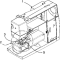
Fig. 1 is the stereogram that the Sewing machines of partly cut-away reaches the holding unit of the fabric paintbrush that is connected with it;
Fig. 2 is enclosed regional detail drawing for the Sewing machines of Fig. 1 by circle 2, and this zone comprises the holding unit that has the fabric paintbrush;
Fig. 3 is in the side view of first operating position for the holding unit of Fig. 1;
Fig. 4 demonstration holding unit as shown in Figure 3 is in the situation of second operating position;
Fig. 5 shows that holding unit as shown in Figure 3 has the situation that is connected the sewing needle on the shank.
The specific embodiment
Fig. 1 shows that the Sewing machines 1 of partly cut-away reaches the holding unit 3 of the fabric paintbrush 5 that is connected with it.Fig. 2 shows the enlarged drawing of the scope that circle 2 encloses among Fig. 1.Shank 9 is outstanding downwards from sewing machine head 7, shank 9 can by a needle bar driving device vertically or the direction of needle road axis 8 move up and down.The bottom of shank 9 connects needle pliering 11 (see figure 5)s that sewing needle 13 and shank 9 are fixed together in the mode that can get loose once again.Fabric paintbrush 5 is fixed on the instrument folder 15 of holding unit 3, and its nib is located immediately on the extended line of needle road axis 8, or slight radial skew and be positioned at the top of embroidery plate 17.Fig. 3 shows the side view as the partly cut-away of the device of Fig. 1.Holding unit 3 has a base 19, and the presser feet post 21 of base 19 is to be used for holding unit is fixed on the common tapered bottom of presser bar 23.Base 19 is the same with presser feet, also is to connect with presser bar 23, for example connects via a fixed bar 25 and presser bar 23.Base 19 has first guide finger 27.If holding unit 3 is fixed on the presser bar 23, then first guide finger 27 can be parallel to 24 downward outstanding corresponding first borings 29 that enter of presser bar axle, and this first boring 29 is positioned on the first gang of 15a that is parallel to the plate 17 of embroidering of instrument folder 15.On first gang of 15a, there is second guide finger 31 that is parallel to first guide finger 27 to project upwards and enters corresponding second boring (not drawing) that is positioned on the base 19.First boring, 29 and second boring is respectively as the place that holds of guide finger (27,31).Outside the guide finger 27,31 except circle, also can use other linear steering assembly and hold the place accordingly.One breach perpendicular to second boring is arranged on base 19, and this breach makes second boring expose at middle the paragraph of base 19, and makes the following contact-making surface 33a that is positioned on the base 19 reach contact-making surface 33b in the position of next-door neighbour's second boring to expose.At these two contact-making surface 33a, there is helical spring 35 to reach between the stop (for example the dynamic resistance ring 37) radially outstanding between the 33b and fixed, thereby dynamic resistance ring 37 is leaned against on the contact-making surface 33b by slight pre-power from second guide finger 31 at following contact-making surface 33a.So just can make instrument folder 15 reference position or first operating positions that are in as shown in Figure 3.Act on from above when enough big extra pressures on the first gang of 15a that is level of instrument folder 15, instrument folder 15 will be pushed down along the opposite direction of first guide finger 27 towards helical spring 35 spring forces.When this extra pressure disappears or becomes enough hour, the spring force of helical spring 35 will press from both sides instrument 15 and upwards push back original reference position.The spring force of spring constant or helical spring 35 want can be fast and the instrument folder 15 that will have instrument (being fabric paintbrush 5 in this example) reliably be elevated to the reference position.Holding unit 3 of the present invention can utilize mobile make instrument folder 15 and fixed thereon instrument according to the rules the mode of shank 9 when sewing of Sewing machines 1 to move.Instrument folder 15 has hookup 39, and the structure of this hookup 39 and set-up mode make shank 9 or a transmission assembly 41 (or the transmission assembly 41 that is connected with shank 9) that is formed on the shank 9 kinetic energy can be transferred to instrument folder 15.In the present embodiment, transmission assembly 41 is bottom surfaces of needle pliering 11.The structure of hookup 39 and set-up mode make transmission assembly 41 when carrying out shank 9 moving up and down in sewing, connect mode Move tool folder 15 that therefore can be according to the rules in this moves a paragraph of circulation with hookup 39 to I haven't seen you for ages.According to a kind of simple embodiment of the present invention, can be directly constitute hookup 39 by the part paragraph of first gang of 15a of instrument folder 15, the needle road axis 8 that prolongs simultaneously can intersect with this part paragraph.Hookup 39 preferably has damper or elastomeric spring assembly (for example spring), to alleviate the bump of the 41 couples of first gang of 15a of transmission assembly on shank 9 or the shank 9.Certainly, also this damper or elastomeric spring assembly can be located on shank 9 or the transmission assembly 41.This elastomeric spring assembly also can make sewing material production spring or the elastic pressure of instrument to processing simultaneously.
According to another embodiment of the present invention, instrument folder 15 also can be used to fix other any instrument, for example the laser devices used of cutter, viscose tube, materials processing.Except the passive type instrument, can certainly be used for fixing active tool, the scissors that drives of laser devices or motor for example, for example these active tool can be connected to control device for sewing-machine by stube cable, to obtain supply of electric power, also can control these active tool in case of necessity by control device for sewing-machine.Instrument folder 15 optional position and the directions that preferably can be set at that have instrument with respect to base 19.
In the present embodiment, the holding unit 3 of fabric paintbrush 5 preferably has guiding mechanism (not drawing), for example can utilize and adjust the height of screw adjustment nib 45 with respect to first gang of 15a.So just can regulation nib 45 and embroidery plate 17 between distance when the reference position of instrument folder, be H=H1, or when shank 9 is fallen fully, be H=H2.When shank 9 was fallen fully, this was equivalent to second operating position that Fig. 4 shows, nib 45 also can be positioned on the embroidery plate 17.This moment, distance H=H2 equaled 0.Can utilize guiding mechanism to adjust nib 45 in this scope and act on pressure on the embroidery plate 17.If fabric 44 is positioned on the embroidery plate 17, can changes nib 45 in a like fashion and act on placement force on the fabric 44, to cooperate the thickness and the kind of fabric 44.
For different fabric paintbrush 5 is directed and be fixed on ad-hoc location on the instrument folder 15, can be equipped with removable joint or adapter 47 and spring chucks 49 for instrument press from both sides 15.For example Fig. 2 demonstration is positioned at the blowout patche formula adapter 47 in nib 45 districts, and is positioned at the elastic fixing clip of the back region of second gang of 15b as anchor clamps 49.In the rear end of holding unit 3 backstop is arranged, its effect is to prevent that fabric paintbrush 5 from moving axially when work.This backstop also can have elasticity and/or can adjust the position, so just can be adaptive with different fabric paintbrushes 5.
Fig. 5 shows that the holding unit as Fig. 3 has the situation that places the sewing needle 13 in the needle pliering 11.If sewing needle 13 is a kind of multiple-pin type sewing needles, and be coaxial wherein, then can be as shown in Figure 5 the nib 45 of fabric paintbrush 5 be arranged at the position that does not have radial displacement with respect to the needle road axis 8 that prolongs with needle road axis 8 without any a sewing needle 13.If not so, then instrument can be pressed from both sides 15 or adapter setting or be oriented such that nib 45 has a radial displacement with respect to needle road axis 8, the order of magnitude of this displacement approximately is 1mm to 25mm, and is adjustable.
According to another embodiment of the present invention, the part (for example or several adapters 47) of instrument folder 15 or instrument folder 15 also can be used for extracting and fixed fabric paintbrush 5 outside other instrument (not drawing).Except the moving vertically of shank 9, other embodiment of the present invention also can utilize the zigzag of Sewing machines 1 to drive rotation or the swing that causes shank 9, makes the instrument that is fixed on the instrument folder 15 produce moving of other or action.Instrument also can be a kind of active element except being a kind of passive type assembly, for example can carry out the laser light source of local heat to fabric 44, or the piezoelectric oscillator (not drawing) used of cutter.
Claims (10)
1. with the holding unit (3) of the instrument of Sewing machines (1) converted goods or non-woven (44), it is characterized by: a presser feet post (21) on the presser bar (23) that is used for holding unit (3) is fixed on Sewing machines (1) is being arranged on the base (19), the instrument folder (15) that extracting tool is used is fixed on the base (19), and instrument folder (15) has a hookup (39) that can exert an influence via the transmission assembly (11) on the shank (9).
2. holding unit as claimed in claim 1 (3) is characterized by: instrument folder (15) is used for extracting or fixing general fabric paintbrush (5).
3. as each described holding unit (3) in claim 1 or 2, it is characterized by: instrument folder (15) is to be supported in a movable manner on the base (19), when the presser bar (23) that is fixed on Sewing machines (1) when holding unit (3) was gone up simultaneously, the bind mode of hookup (39) and instrument folder (15) can make hookup (39) and be driven because of moving of shank (9).
4. as each described holding unit (3) in the claim 1 to 3, it is characterized by: hookup (39) has a damper or elastomeric spring assembly.
5. as each described holding unit (3) in the claim 1 to 4, it is characterized by: instrument folder (15) has first strand (15a) and second strand (15b), wherein first strand (15a) is positioned on the base (19) in a movable manner, and second strand (15b) and first strand (15a) are with (90 °+α) link together at a fixing or adjustable inclination angle.
6. holding unit as claimed in claim 5 (3) is characterized by: second strand (15b) has the utensil that an energy gets loose the instrument that is fixed once again at an assigned position.
7. holding unit as claimed in claim 6 (3) is characterized by: this utensil has the removable adapter (47) of the assigned position of an instrument.
8. as each described holding unit in the claim 1 to 7, it is characterized by: have a guiding mechanism that can limit moving range and/or influence relative position.
9. as each described holding unit (3) in the claim 1 to 8, it is characterized by: on base (19) and/or instrument folder (15), a guide finger (27 is arranged, 31) or other suitable linear steering assembly, wherein instrument folder (15) with holding unit (3) that the presser bar (23) of Sewing machines (1) is connected on be to be arranged in the mode that is parallel to presser feet axle (24) and can promote on the base (19), instrument presss from both sides (15) and is retained on the reference position or first operating position of base (19) in the effect that only is subjected to a spring force under the effect that does not have other power simultaneously.
10. method with tool processes fabric or non-woven (44), it is characterized by: instrument being fixed on the presser bar (23), and driving instrument or change the action of instrument via the effect that shank moves as each described holding unit (3) in the claim 1 to 9.
Applications Claiming Priority (2)
| Application Number | Priority Date | Filing Date | Title |
|---|---|---|---|
| CH00204/09 | 2009-02-11 | ||
| CH00204/09A CH700377A1 (en) | 2009-02-11 | 2009-02-11 | Holding device for a tool for machining a textile or non-textile fabric in a sewing machine. |
Publications (1)
| Publication Number | Publication Date |
|---|---|
| CN101798731A true CN101798731A (en) | 2010-08-11 |
Family
ID=42236340
Family Applications (1)
| Application Number | Title | Priority Date | Filing Date |
|---|---|---|---|
| CN201010113846A Pending CN101798731A (en) | 2009-02-11 | 2010-02-05 | Holding unit with the instrument of Sewing machines converted goods or non-woven |
Country Status (7)
| Country | Link |
|---|---|
| US (1) | US8281726B2 (en) |
| EP (1) | EP2221409B1 (en) |
| JP (1) | JP5586246B2 (en) |
| CN (1) | CN101798731A (en) |
| AT (1) | ATE550470T1 (en) |
| CH (1) | CH700377A1 (en) |
| TW (1) | TW201037117A (en) |
Families Citing this family (7)
| Publication number | Priority date | Publication date | Assignee | Title |
|---|---|---|---|---|
| CH706492A1 (en) | 2012-05-09 | 2013-11-15 | Bernina Int Ag | Apparatus and method for punching a sheet with a sewing machine. |
| EP3068937B1 (en) * | 2013-11-14 | 2019-01-09 | Alberto Landoni | Multi-needle quilting machine and corresponding quilting method |
| JP2015149992A (en) * | 2014-02-10 | 2015-08-24 | ブラザー工業株式会社 | sewing machine |
| JP2015149991A (en) | 2014-02-10 | 2015-08-24 | ブラザー工業株式会社 | sewing machine |
| JP6783988B2 (en) * | 2017-03-23 | 2020-11-11 | 豊田合成株式会社 | Reinforcing liquid application device for airbags |
| CN113201866B (en) * | 2021-05-19 | 2022-07-29 | 安徽戴家工艺有限公司 | Automatic sewing device for cushion of hanging chair |
| CN114436052A (en) * | 2022-01-21 | 2022-05-06 | 海洋石油工程股份有限公司 | Non-return device for hose recovery |
Citations (4)
| Publication number | Priority date | Publication date | Assignee | Title |
|---|---|---|---|---|
| US4151806A (en) * | 1976-08-31 | 1979-05-01 | Katsuji Mori | Multiple-stitch zigzag stitching devices for sewing machines |
| JPH07133575A (en) * | 1991-02-28 | 1995-05-23 | Janome Sewing Mach Co Ltd | Sewing machine with embroidery function having pointillistic device |
| CN1633928A (en) * | 2003-12-31 | 2005-07-06 | 程旭辉 | Method and apparatus for automatic making garment templet and bushing plate |
| US20080196646A1 (en) * | 2007-02-21 | 2008-08-21 | Brother Kogyo Kabushiki Kaisha | Sewing machine and computer-readable recording medium with recorded sewing machine control program |
Family Cites Families (17)
| Publication number | Priority date | Publication date | Assignee | Title |
|---|---|---|---|---|
| US223107A (en) * | 1879-12-30 | Improvement in tuck-markers for sewing-machines | ||
| US947506A (en) * | 1909-06-14 | 1910-01-25 | Isidor Weinbach | Combination pressure-foot and trimming attachment for sewing-machines. |
| US2511275A (en) * | 1948-11-10 | 1950-06-13 | Aune E Leino | Attachment for sewing machines for repairing hosiery |
| DE2544165C3 (en) * | 1975-10-03 | 1978-08-10 | Pfaff Industriemaschinen Gmbh, 6750 Kaiserslautern | Equipment on sewing machines for prepunching the sewing material |
| JPH0673579B2 (en) * | 1984-06-19 | 1994-09-21 | 蛇の目ミシン工業株式会社 | Sewing machine pen writing device |
| DE3902333A1 (en) * | 1989-01-27 | 1990-08-09 | Union Special Gmbh | METHOD FOR DETECTING A POSITION OF A SEWING MATERIAL ON A CONTROLLED DRIVING MACHINE, AND DEVICE FOR CARRYING OUT THE METHOD |
| JPH05261187A (en) * | 1991-03-04 | 1993-10-12 | Janome Sewing Mach Co Ltd | Sewing machine having embroidering function and mark cutter device |
| JPH05317546A (en) * | 1991-03-25 | 1993-12-03 | Janome Sewing Mach Co Ltd | Sewing machine with embroidery function provided with embroidery pattern plotting function |
| JP3370129B2 (en) * | 1993-03-01 | 2003-01-27 | 株式会社バルダン | Loop seam forming device |
| JP3420648B2 (en) * | 1994-12-19 | 2003-06-30 | 株式会社バルダン | Sewing machine with coding function |
| JP3519034B2 (en) * | 2000-01-24 | 2004-04-12 | 株式会社タチエス | Sewing device for trim cover of vehicle seat |
| JP2002233682A (en) * | 2001-02-09 | 2002-08-20 | Kyowa:Kk | Pen for sewing machine |
| JP2007222188A (en) * | 2004-03-29 | 2007-09-06 | Tokai Ind Sewing Mach Co Ltd | Sequin feeder |
| JP2006110074A (en) * | 2004-10-14 | 2006-04-27 | Barudan Co Ltd | Sequin feeder |
| JP5091601B2 (en) * | 2006-10-13 | 2012-12-05 | 東海工業ミシン株式会社 | Sequin feeder and sewing machine capable of sequin sewing |
| JP2008220559A (en) * | 2007-03-12 | 2008-09-25 | Barudan Co Ltd | Multi-needle embroidery machine |
| EP2172585B1 (en) * | 2008-09-04 | 2011-03-30 | BERNINA International AG | Device and method for cutting textile and non-textile measured material |
-
2009
- 2009-02-11 CH CH00204/09A patent/CH700377A1/en not_active Application Discontinuation
-
2010
- 2010-01-18 AT AT10405007T patent/ATE550470T1/en active
- 2010-01-18 EP EP10405007A patent/EP2221409B1/en active Active
- 2010-01-22 JP JP2010011728A patent/JP5586246B2/en active Active
- 2010-02-05 TW TW099103420A patent/TW201037117A/en unknown
- 2010-02-05 US US12/700,789 patent/US8281726B2/en active Active
- 2010-02-05 CN CN201010113846A patent/CN101798731A/en active Pending
Patent Citations (4)
| Publication number | Priority date | Publication date | Assignee | Title |
|---|---|---|---|---|
| US4151806A (en) * | 1976-08-31 | 1979-05-01 | Katsuji Mori | Multiple-stitch zigzag stitching devices for sewing machines |
| JPH07133575A (en) * | 1991-02-28 | 1995-05-23 | Janome Sewing Mach Co Ltd | Sewing machine with embroidery function having pointillistic device |
| CN1633928A (en) * | 2003-12-31 | 2005-07-06 | 程旭辉 | Method and apparatus for automatic making garment templet and bushing plate |
| US20080196646A1 (en) * | 2007-02-21 | 2008-08-21 | Brother Kogyo Kabushiki Kaisha | Sewing machine and computer-readable recording medium with recorded sewing machine control program |
Also Published As
| Publication number | Publication date |
|---|---|
| TW201037117A (en) | 2010-10-16 |
| ATE550470T1 (en) | 2012-04-15 |
| EP2221409B1 (en) | 2012-03-21 |
| US8281726B2 (en) | 2012-10-09 |
| US20100199900A1 (en) | 2010-08-12 |
| JP5586246B2 (en) | 2014-09-10 |
| JP2010185165A (en) | 2010-08-26 |
| CH700377A1 (en) | 2010-08-13 |
| EP2221409A1 (en) | 2010-08-25 |
Similar Documents
| Publication | Publication Date | Title |
|---|---|---|
| CN101798731A (en) | Holding unit with the instrument of Sewing machines converted goods or non-woven | |
| CN101775712B (en) | Multifunctional digital control sewing machine for feeding by clamping cloth sheets through template | |
| TR200701916T1 (en) | Multi Needle Embroidery Machine | |
| JP2001334087A (en) | Presser foot system for sewing machine | |
| JP6262396B1 (en) | Ink marker sewing device | |
| US8671858B2 (en) | Servo driven crank adjusted shifting mechanism | |
| CN206345998U (en) | A kind of automatic shearing wire type roller quilter | |
| JPH0578961A (en) | Device for yarn tension of warp knitting machine | |
| HK1112944A1 (en) | Rectilinear knitting machine and corresponding knitting method thereof | |
| CN102851881A (en) | Method for operating a chain-stitch sewing machine and chain-stitch sewing machine | |
| JP5468234B2 (en) | Loop material feeder | |
| CN207878064U (en) | A kind of intelligent automation embroidery machine | |
| CN207987489U (en) | The punch block component of arbitrary needle position carving hole knife | |
| KR200389572Y1 (en) | Spangle supply device of embroidery machine | |
| CN207376243U (en) | A kind of embroidery pearl head | |
| CN111172676A (en) | Automatic sewing device for clamp plate of sewing machine | |
| JPH08226067A (en) | Cloth presser for embroidering machine | |
| JP2003135874A (en) | Embroidering device, and device and method for producing pattern | |
| CN108130662A (en) | A kind of intelligent automation embroidery machine | |
| CN213835846U (en) | Multi-needle embroidery machine for quilt production | |
| EP1472399A1 (en) | Device and method to apply paillettes on fabrics in a sewing machine, and multi-needle sewing machine comprising said device | |
| CN206512393U (en) | A kind of new single-needle quilter | |
| CN212175194U (en) | Single-needle flat carriage for trademark sewing | |
| US20210017684A1 (en) | Sewing machine | |
| CN206345999U (en) | A kind of automatic shearing wire type single-needle quilter |
Legal Events
| Date | Code | Title | Description |
|---|---|---|---|
| C06 | Publication | ||
| PB01 | Publication | ||
| C10 | Entry into substantive examination | ||
| SE01 | Entry into force of request for substantive examination | ||
| C02 | Deemed withdrawal of patent application after publication (patent law 2001) | ||
| WD01 | Invention patent application deemed withdrawn after publication |
Application publication date: 20100811 |