EP2217911B1 - Particle detection - Google Patents
Particle detection Download PDFInfo
- Publication number
- EP2217911B1 EP2217911B1 EP08849716.9A EP08849716A EP2217911B1 EP 2217911 B1 EP2217911 B1 EP 2217911B1 EP 08849716 A EP08849716 A EP 08849716A EP 2217911 B1 EP2217911 B1 EP 2217911B1
- Authority
- EP
- European Patent Office
- Prior art keywords
- light
- scattering
- smoke
- light source
- laser
- Prior art date
- Legal status (The legal status is an assumption and is not a legal conclusion. Google has not performed a legal analysis and makes no representation as to the accuracy of the status listed.)
- Active
Links
- 239000002245 particle Substances 0.000 title claims description 110
- 238000001514 detection method Methods 0.000 title claims description 56
- 238000000034 method Methods 0.000 claims description 137
- 230000003287 optical effect Effects 0.000 claims description 44
- 230000007246 mechanism Effects 0.000 claims description 29
- 238000005286 illumination Methods 0.000 claims description 12
- 238000004458 analytical method Methods 0.000 claims description 9
- 238000002310 reflectometry Methods 0.000 claims description 3
- 239000000779 smoke Substances 0.000 description 126
- 239000000428 dust Substances 0.000 description 45
- 238000005259 measurement Methods 0.000 description 33
- 230000035945 sensitivity Effects 0.000 description 29
- 230000008901 benefit Effects 0.000 description 18
- 230000000694 effects Effects 0.000 description 16
- 230000010354 integration Effects 0.000 description 15
- 230000005855 radiation Effects 0.000 description 15
- 238000003384 imaging method Methods 0.000 description 14
- 230000002829 reductive effect Effects 0.000 description 13
- 239000000463 material Substances 0.000 description 12
- 238000012937 correction Methods 0.000 description 11
- 238000009434 installation Methods 0.000 description 11
- 230000008569 process Effects 0.000 description 11
- 241000238631 Hexapoda Species 0.000 description 10
- 230000001965 increasing effect Effects 0.000 description 10
- 230000004044 response Effects 0.000 description 10
- 230000008859 change Effects 0.000 description 9
- 238000009826 distribution Methods 0.000 description 9
- 230000006870 function Effects 0.000 description 9
- 239000007787 solid Substances 0.000 description 9
- 238000001914 filtration Methods 0.000 description 8
- 238000012544 monitoring process Methods 0.000 description 8
- 238000011109 contamination Methods 0.000 description 7
- 238000012545 processing Methods 0.000 description 7
- 230000009467 reduction Effects 0.000 description 7
- 239000000243 solution Substances 0.000 description 6
- 238000012935 Averaging Methods 0.000 description 5
- 238000004422 calculation algorithm Methods 0.000 description 5
- 238000004364 calculation method Methods 0.000 description 5
- 230000001934 delay Effects 0.000 description 5
- 238000012423 maintenance Methods 0.000 description 5
- 230000002123 temporal effect Effects 0.000 description 5
- 241000239290 Araneae Species 0.000 description 4
- 238000010521 absorption reaction Methods 0.000 description 4
- 238000013459 approach Methods 0.000 description 4
- 238000000149 argon plasma sintering Methods 0.000 description 4
- 230000005540 biological transmission Effects 0.000 description 4
- 230000000903 blocking effect Effects 0.000 description 4
- 230000001419 dependent effect Effects 0.000 description 4
- 230000005684 electric field Effects 0.000 description 4
- 238000005516 engineering process Methods 0.000 description 4
- 230000001976 improved effect Effects 0.000 description 4
- 239000003550 marker Substances 0.000 description 4
- 230000001052 transient effect Effects 0.000 description 4
- IMNFDUFMRHMDMM-UHFFFAOYSA-N N-Heptane Chemical compound CCCCCCC IMNFDUFMRHMDMM-UHFFFAOYSA-N 0.000 description 3
- YXFVVABEGXRONW-UHFFFAOYSA-N Toluene Chemical compound CC1=CC=CC=C1 YXFVVABEGXRONW-UHFFFAOYSA-N 0.000 description 3
- 238000004891 communication Methods 0.000 description 3
- 230000001010 compromised effect Effects 0.000 description 3
- 230000001276 controlling effect Effects 0.000 description 3
- 238000001816 cooling Methods 0.000 description 3
- 230000006378 damage Effects 0.000 description 3
- 230000006872 improvement Effects 0.000 description 3
- 238000012986 modification Methods 0.000 description 3
- 230000004048 modification Effects 0.000 description 3
- 238000001228 spectrum Methods 0.000 description 3
- 230000007306 turnover Effects 0.000 description 3
- LFQSCWFLJHTTHZ-UHFFFAOYSA-N Ethanol Chemical compound CCO LFQSCWFLJHTTHZ-UHFFFAOYSA-N 0.000 description 2
- 230000009471 action Effects 0.000 description 2
- 230000003213 activating effect Effects 0.000 description 2
- 230000002238 attenuated effect Effects 0.000 description 2
- 230000003190 augmentative effect Effects 0.000 description 2
- 230000009286 beneficial effect Effects 0.000 description 2
- 238000004140 cleaning Methods 0.000 description 2
- 230000001427 coherent effect Effects 0.000 description 2
- 239000004020 conductor Substances 0.000 description 2
- 239000000356 contaminant Substances 0.000 description 2
- 230000003247 decreasing effect Effects 0.000 description 2
- 230000003292 diminished effect Effects 0.000 description 2
- -1 for example Substances 0.000 description 2
- 230000017525 heat dissipation Effects 0.000 description 2
- 230000001788 irregular Effects 0.000 description 2
- 238000009533 lab test Methods 0.000 description 2
- 230000007935 neutral effect Effects 0.000 description 2
- 239000004033 plastic Substances 0.000 description 2
- 229920003023 plastic Polymers 0.000 description 2
- 230000001105 regulatory effect Effects 0.000 description 2
- 230000011664 signaling Effects 0.000 description 2
- 238000009987 spinning Methods 0.000 description 2
- 238000007619 statistical method Methods 0.000 description 2
- 230000001629 suppression Effects 0.000 description 2
- 230000001360 synchronised effect Effects 0.000 description 2
- 230000008685 targeting Effects 0.000 description 2
- 238000012546 transfer Methods 0.000 description 2
- 229910052724 xenon Inorganic materials 0.000 description 2
- FHNFHKCVQCLJFQ-UHFFFAOYSA-N xenon atom Chemical compound [Xe] FHNFHKCVQCLJFQ-UHFFFAOYSA-N 0.000 description 2
- IJGRMHOSHXDMSA-UHFFFAOYSA-N Atomic nitrogen Chemical compound N#N IJGRMHOSHXDMSA-UHFFFAOYSA-N 0.000 description 1
- 0 C*=CCCN=*C Chemical compound C*=CCCN=*C 0.000 description 1
- UFHFLCQGNIYNRP-UHFFFAOYSA-N Hydrogen Chemical compound [H][H] UFHFLCQGNIYNRP-UHFFFAOYSA-N 0.000 description 1
- 241001465754 Metazoa Species 0.000 description 1
- 206010034960 Photophobia Diseases 0.000 description 1
- 206010069201 Smoke sensitivity Diseases 0.000 description 1
- 239000004904 UV filter Substances 0.000 description 1
- 208000027418 Wounds and injury Diseases 0.000 description 1
- 238000000862 absorption spectrum Methods 0.000 description 1
- 230000003044 adaptive effect Effects 0.000 description 1
- 230000001668 ameliorated effect Effects 0.000 description 1
- QVGXLLKOCUKJST-UHFFFAOYSA-N atomic oxygen Chemical compound [O] QVGXLLKOCUKJST-UHFFFAOYSA-N 0.000 description 1
- 238000005266 casting Methods 0.000 description 1
- 229920002678 cellulose Polymers 0.000 description 1
- 239000001913 cellulose Substances 0.000 description 1
- 239000002801 charged material Substances 0.000 description 1
- 238000012993 chemical processing Methods 0.000 description 1
- 238000000576 coating method Methods 0.000 description 1
- 230000000295 complement effect Effects 0.000 description 1
- 230000003750 conditioning effect Effects 0.000 description 1
- 238000010276 construction Methods 0.000 description 1
- 230000009193 crawling Effects 0.000 description 1
- 230000007423 decrease Effects 0.000 description 1
- 230000003111 delayed effect Effects 0.000 description 1
- 238000013461 design Methods 0.000 description 1
- 230000023077 detection of light stimulus Effects 0.000 description 1
- 230000001627 detrimental effect Effects 0.000 description 1
- 238000009792 diffusion process Methods 0.000 description 1
- 238000010790 dilution Methods 0.000 description 1
- 239000012895 dilution Substances 0.000 description 1
- 229910001873 dinitrogen Inorganic materials 0.000 description 1
- 229910001882 dioxygen Inorganic materials 0.000 description 1
- 238000006073 displacement reaction Methods 0.000 description 1
- 230000009977 dual effect Effects 0.000 description 1
- 230000005670 electromagnetic radiation Effects 0.000 description 1
- 230000002708 enhancing effect Effects 0.000 description 1
- 230000007613 environmental effect Effects 0.000 description 1
- 235000019441 ethanol Nutrition 0.000 description 1
- 239000000446 fuel Substances 0.000 description 1
- 239000011521 glass Substances 0.000 description 1
- 230000005484 gravity Effects 0.000 description 1
- 229910052736 halogen Inorganic materials 0.000 description 1
- 231100001261 hazardous Toxicity 0.000 description 1
- 210000002837 heart atrium Anatomy 0.000 description 1
- 238000010438 heat treatment Methods 0.000 description 1
- 229930195733 hydrocarbon Natural products 0.000 description 1
- 150000002430 hydrocarbons Chemical class 0.000 description 1
- 239000001257 hydrogen Substances 0.000 description 1
- 229910052739 hydrogen Inorganic materials 0.000 description 1
- 230000001939 inductive effect Effects 0.000 description 1
- 238000002329 infrared spectrum Methods 0.000 description 1
- 230000002401 inhibitory effect Effects 0.000 description 1
- 208000014674 injury Diseases 0.000 description 1
- 239000002917 insecticide Substances 0.000 description 1
- 238000009413 insulation Methods 0.000 description 1
- 230000002452 interceptive effect Effects 0.000 description 1
- 238000005304 joining Methods 0.000 description 1
- 208000013469 light sensitivity Diseases 0.000 description 1
- 230000000670 limiting effect Effects 0.000 description 1
- 239000004973 liquid crystal related substance Substances 0.000 description 1
- 230000004807 localization Effects 0.000 description 1
- 230000007774 longterm Effects 0.000 description 1
- 238000004519 manufacturing process Methods 0.000 description 1
- 230000000873 masking effect Effects 0.000 description 1
- 238000013178 mathematical model Methods 0.000 description 1
- 238000000691 measurement method Methods 0.000 description 1
- 239000000203 mixture Substances 0.000 description 1
- 239000005392 opalescent glass Substances 0.000 description 1
- 238000013021 overheating Methods 0.000 description 1
- 239000001301 oxygen Substances 0.000 description 1
- 230000036961 partial effect Effects 0.000 description 1
- 239000013618 particulate matter Substances 0.000 description 1
- 238000003672 processing method Methods 0.000 description 1
- 230000002035 prolonged effect Effects 0.000 description 1
- 230000010349 pulsation Effects 0.000 description 1
- 239000005871 repellent Substances 0.000 description 1
- 230000002940 repellent Effects 0.000 description 1
- 230000000630 rising effect Effects 0.000 description 1
- 238000005070 sampling Methods 0.000 description 1
- 229910052594 sapphire Inorganic materials 0.000 description 1
- 239000010980 sapphire Substances 0.000 description 1
- 229920006395 saturated elastomer Polymers 0.000 description 1
- 238000013341 scale-up Methods 0.000 description 1
- 230000003678 scratch resistant effect Effects 0.000 description 1
- 238000000926 separation method Methods 0.000 description 1
- 239000002904 solvent Substances 0.000 description 1
- 230000003595 spectral effect Effects 0.000 description 1
- 239000007921 spray Substances 0.000 description 1
- 239000000126 substance Substances 0.000 description 1
- 230000008093 supporting effect Effects 0.000 description 1
- 238000010809 targeting technique Methods 0.000 description 1
- 238000012360 testing method Methods 0.000 description 1
- 230000007704 transition Effects 0.000 description 1
- 230000001960 triggered effect Effects 0.000 description 1
- 238000012795 verification Methods 0.000 description 1
- 238000001429 visible spectrum Methods 0.000 description 1
- 230000000007 visual effect Effects 0.000 description 1
Images


Classifications
-
- G—PHYSICS
- G01—MEASURING; TESTING
- G01N—INVESTIGATING OR ANALYSING MATERIALS BY DETERMINING THEIR CHEMICAL OR PHYSICAL PROPERTIES
- G01N21/00—Investigating or analysing materials by the use of optical means, i.e. using sub-millimetre waves, infrared, visible or ultraviolet light
- G01N21/17—Systems in which incident light is modified in accordance with the properties of the material investigated
- G01N21/47—Scattering, i.e. diffuse reflection
- G01N21/49—Scattering, i.e. diffuse reflection within a body or fluid
- G01N21/53—Scattering, i.e. diffuse reflection within a body or fluid within a flowing fluid, e.g. smoke
- G01N21/532—Scattering, i.e. diffuse reflection within a body or fluid within a flowing fluid, e.g. smoke with measurement of scattering and transmission
-
- G—PHYSICS
- G01—MEASURING; TESTING
- G01N—INVESTIGATING OR ANALYSING MATERIALS BY DETERMINING THEIR CHEMICAL OR PHYSICAL PROPERTIES
- G01N15/00—Investigating characteristics of particles; Investigating permeability, pore-volume or surface-area of porous materials
- G01N15/06—Investigating concentration of particle suspensions
- G01N15/0656—Investigating concentration of particle suspensions using electric, e.g. electrostatic methods or magnetic methods
-
- G—PHYSICS
- G01—MEASURING; TESTING
- G01N—INVESTIGATING OR ANALYSING MATERIALS BY DETERMINING THEIR CHEMICAL OR PHYSICAL PROPERTIES
- G01N21/00—Investigating or analysing materials by the use of optical means, i.e. using sub-millimetre waves, infrared, visible or ultraviolet light
- G01N21/17—Systems in which incident light is modified in accordance with the properties of the material investigated
- G01N21/47—Scattering, i.e. diffuse reflection
- G01N21/49—Scattering, i.e. diffuse reflection within a body or fluid
- G01N21/53—Scattering, i.e. diffuse reflection within a body or fluid within a flowing fluid, e.g. smoke
-
- G—PHYSICS
- G08—SIGNALLING
- G08B—SIGNALLING OR CALLING SYSTEMS; ORDER TELEGRAPHS; ALARM SYSTEMS
- G08B17/00—Fire alarms; Alarms responsive to explosion
- G08B17/10—Actuation by presence of smoke or gases, e.g. automatic alarm devices for analysing flowing fluid materials by the use of optical means
- G08B17/103—Actuation by presence of smoke or gases, e.g. automatic alarm devices for analysing flowing fluid materials by the use of optical means using a light emitting and receiving device
- G08B17/107—Actuation by presence of smoke or gases, e.g. automatic alarm devices for analysing flowing fluid materials by the use of optical means using a light emitting and receiving device for detecting light-scattering due to smoke
-
- G—PHYSICS
- G08—SIGNALLING
- G08B—SIGNALLING OR CALLING SYSTEMS; ORDER TELEGRAPHS; ALARM SYSTEMS
- G08B17/00—Fire alarms; Alarms responsive to explosion
- G08B17/12—Actuation by presence of radiation or particles, e.g. of infrared radiation or of ions
- G08B17/125—Actuation by presence of radiation or particles, e.g. of infrared radiation or of ions by using a video camera to detect fire or smoke
-
- G—PHYSICS
- G08—SIGNALLING
- G08B—SIGNALLING OR CALLING SYSTEMS; ORDER TELEGRAPHS; ALARM SYSTEMS
- G08B29/00—Checking or monitoring of signalling or alarm systems; Prevention or correction of operating errors, e.g. preventing unauthorised operation
- G08B29/18—Prevention or correction of operating errors
- G08B29/185—Signal analysis techniques for reducing or preventing false alarms or for enhancing the reliability of the system
-
- H—ELECTRICITY
- H04—ELECTRIC COMMUNICATION TECHNIQUE
- H04N—PICTORIAL COMMUNICATION, e.g. TELEVISION
- H04N5/00—Details of television systems
- H04N5/30—Transforming light or analogous information into electric information
- H04N5/32—Transforming X-rays
-
- H—ELECTRICITY
- H04—ELECTRIC COMMUNICATION TECHNIQUE
- H04N—PICTORIAL COMMUNICATION, e.g. TELEVISION
- H04N7/00—Television systems
- H04N7/18—Closed-circuit television [CCTV] systems, i.e. systems in which the video signal is not broadcast
-
- G—PHYSICS
- G01—MEASURING; TESTING
- G01N—INVESTIGATING OR ANALYSING MATERIALS BY DETERMINING THEIR CHEMICAL OR PHYSICAL PROPERTIES
- G01N15/00—Investigating characteristics of particles; Investigating permeability, pore-volume or surface-area of porous materials
- G01N15/06—Investigating concentration of particle suspensions
- G01N15/075—Investigating concentration of particle suspensions by optical means
Definitions
- the present invention relates to systems and methods applicable to particle detection systems.
- the preferred embodiment of the present invention relates to systems and methods adapted to detect smoke, and more particularly to systems and methods applicable to active video smoke detection. While it is convenient to describe the present invention in this context, the present invention should not be seen as being limited to that exemplary field of application.
- Active video smoke detection is the name that has been coined by Xtralis Pty Ltd for particle detection systems (most preferably smoke detection systems) that use video analysis techniques to detect smoke in an air volume that is actively illuminated, e.g. by a laser or other electromagnetic (EM) radiation source.
- AVSD Active video smoke detection
- one problem that may be faced by such system is that of objects other than smoke entering the beam or field of view of the image sensor. This can have several effects; firstly it can cause a false alarm by imitating the effect of smoke. Secondly, encroaching objects may prevent the system from detecting smoke by blocking the path of the beam across the volume being monitored or by blocking the view of part of the beam by the image sensor. Thirdly, it may be unsafe if a person (or animal) passes through the beam. Thus, such systems need mechanisms and methods for both preventing the encroachment of objects into the beam, and for the amelioration of the negative effects on the system when such an encroachment occurs.
- An AVSD system will typically have a EM radiation source shining a EM radiation beam across an extended distance. In most circumstances system components will need to be accurately aligned across this extended distance. Alignment of the components will need to be performed at commissioning and periodically during the operation of the system to ensure correct operation.
- an AVSD system Due to the relative difficulty in controlling the environment in air volumes suited to the use of an AVSD system, e.g. large areas, high roofed enclosed areas such as atriums etc. an AVSD system must be sufficiently robust to cope with a wide range of environments. For example such environments often have a wide range of possible background light levels, e.g. differences in lighting levels between day and night, and may also have rapidly fluctuating background light levels.
- WO 2006/050570 provides use of one or more emitted beams of radiation, for example, laser beam(s), in combination with an image capturing means, for example, one or more video cameras and/or optical elements to detect particles, for example, smoke particles, located in an open space.
- an image capturing means for example, one or more video cameras and/or optical elements to detect particles, for example, smoke particles, located in an open space.
- GB2426323 discloses a method of determining alignment of a beam in a projected light beam based particle detector system adapted to detect particles directly in a volume being monitored, the method including: emitting a beam of light and directing the beam across a volume being monitored and on a reflective target; scanning the beam of light across a predetermined area where the reflective target is likely to be; receiving at least a portion of the beam of light reflected by the reflective target at a light sensor; analysing the light received as a result of scanning of the beam based on at least one measured parameter of the received light; and based on the analysis determining an alignment of the beam of light.
- the present invention relates to an AVSD system and a method of determining alignment of a beam in an AVSD system according to the appended claims.
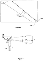
- an AVSD system it may be necessary to determine if there are any obstructions in the field of view of the optical receiver that may reduce the sensor's ability to detect smoke over the expected area of operation. Specifically, it is necessary to monitor the sector defined by the imaginary line connecting the receiver to the light source and the line formed by the projection of the collimated light beam as shown in Figure 1 .
- FIG. 1 illustrates a typical AVSD particle detection system 100 including a light source 102 and a receiver 104 in the form of a camera.
- the light source is arranged to emit a beam of light 106 that traverses a space being monitored.
- the camera 104 is aligned to view the light source 102 and its beam 106 and to detect the level of light scattered from the beam 106 by particles present in the space being monitored.
- the critical volume 110 in which obstructions must be monitored is between the beam 106 and the imaginary line joining 108 the camera and the light source 102. If obstructions occur in this region the beam 106 will be obscured from the view of the camera 104 and thus the camera will not be able to detect scattered light from the entire beam and the detection sensitivity of the system will be compromised.
- the image sensor 104 (and possibly the emitter 102) is connected to a processor 107 which is adapted to analyse the images captured, either with or without source illumination data, to determine detect the presence of particles within the volume on the basis of radiation captured in the images
- FIG. 1 shows an exemplary arrangement in which the AVSD system of Figure 1 has been augmented with a second, rearward facing camera 112 and a source 103 of uncollimated light that projects light over the region 110.
- the camera rearward facing 112 is arranged to view the surface behind the region 110 that is illuminated by the source 103 of un-collimated light.
- an object 114 intruding into the volume 110 will cast a shadow 116 that can be observed by the rearward looking camera 112.
- Images taken by camera 112 may be processed to recognise a variation from a pre-recorded "reference" image known to be free of obstructions. If a variation between an image frame from the second camera 112 and the reference image is determined by the processing to be significant then a fault alarm can be raised.
- the image processing may determine the presence of a shadow caused by an obstruction by comparing intensities of adjacent image regions and determining that there is sufficient variation between neighbouring regions to detect a shadow.
- the light source 103 be non-visible as this offers the advantage that it will be unobtrusive to people working in the area and therefore not cause disturbance.
- the light source 103 could be a Xenon Flash lamp.
- the system can be arranged to trigger a fault condition if a shadow of a predetermined size persists for longer than a predetermined time.
- the length of the predetermined time should be long enough to avoid going into a fault condition over a transient obstruction, such as a bird quickly flying through the region 110.
- an AVSD system it would be advantageous to have its major components located in close proximity to each other, e.g. at the same end of the protected space, as opposed to on opposite ends of the room as in the systems of Figures 1 and 2 .
- Such an arrangement removes the need to provide power and signalling to opposite sides of the protected space, and consequently may result in a lower cost of installation of the system.
- this aim may be achieved using a special purpose reflector placed at the distal end of the protected space, away from the light source and receiver.
- the light beam is directed toward the reflector, which is designed to return a reflected beam to a required target position, which may be adjacent the
- the reflector may have greater than 90 degree "corners" to cause beam to be reflected at a fixed angle to incident beam.
- the reflector may alternatively be a convex mirror where the beam is steered to be reflected to a known target position.
- the mirror may be actually implemented as a set of flat mirrors or could be concave too, allowing for a convergent reflected beam.
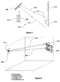
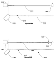
- Figure 3 illustrates in an embodiment of this aspect of the present invention 300 where the receiver 104 and light source 102 are mounted relatively nearby each other. In a particularly preferred form they may be substantially co-located, e.g. in the same housing.
- the light beam 306 is directed at a planar reflective surface 302, and the camera 104 is aligned to give a field-of-view (illustrated by the lines 304) which includes the reflector 302, part of the incident beam 306, the entire reflected beam 308, and the target 310.
- the target spot 310 may be allowed to fall out of the direct view of the camera 104 if other methods for its supervision are provided.
- the reflector 302 may be mounted on an adjustable mounting that enables its angle to be manually adjusted at installation e.g. by the use of adjustment screws or the like.
- a further improvement may be obtained to maintain long-term positional stability of the reflected beam, by using an electro-mechanically driven tilt mechanism such as the one illustrated in Figure 33 . While this requires power to be provided to the far end of the system, such a system may have very low average power consumption, permitting it to employ batteries with a long life.
- Many alternative actuator types will be known to those skilled in the art that can perform this function including geared electric motors, stepper motors, galvanic mirrors, solenoids, piezo-electric actuators, thermal actuators and the like.
- the angular position of the mirror 302 may be advantageously set initially, and thereafter maintained, by remote control. This control may be performed automatically by software in the detection system using the visual image from the camera and other inputs. Similarly, the beam 306 emanating from the light source 102 may be automatically steered to remain directed on target at the reflector 302. Suitable mechanisms for beam steering are disclosed elsewhere herein.
- the ability to scan the reflected beam 308 by adjustment of the angle of the mirror 302 may be usefully employed to verify that the field of view of the camera has not become excessively obstructed.
- the reflected beam can be periodically scanned toward the camera. If during the scan the target spot disappears unexpectedly this is likely to be caused by an obstruction. Alternatively, if scattering (or an unexpected change in scattering) is detected during the scanning of the beam 306, this can be caused by the edge of an obstruction, which can be recognised by the detection software.
- acceptably small obstructions e.g. vertical building columns or fixtures
- the reflector 302 may be curved, or made up of a number of adjoining flat mirrors each positioned at a slightly different angles. With this type of reflector the path of the reflected beam 308 can be altered from the light source by targeting a different portion of the reflector surface.
- the reflector 302 may be a variant on the corner-reflector arrangement. Normally, such reflectors use reflective surfaces arranged orthogonally so that the light beam is reflected substantially directly back to the source, regardless of the point on the reflector where it lands. However, when the reflector surfaces are placed at 90 degrees plus an angle ⁇ the reflected beam is always directed back at an angle of 2 x ⁇ from the incident beam.
- the light source 102 and the receiver 104 may be placed a short distance apart, and a conventional 180 degree retro-reflector 302 employed. In this way, the incident beam 306 and reflected beam 308 remain on the same path, in opposite directions.
- a separate detection system in the form of, for example, a photo-diode located on the light source 102 may be employed. The signal from this device may also be used as a confirming transmission-loss smoke-detector in a manner described in more detail below.
- telescopic imaging optics may be used to increase the effective range and sensitivity of the detection device.
- the telescopic imaging optics may take the form of a commercially available zoom lens.
- the magnification of many commercially available lenses can be electrically controlled, allowing the system software to selectively zoom in on a part of the image to improve performance in that region. This may be particularly advantageous if a potentially ambiguous low level signal is identified in a specific area.
- the telescopic optics can allow the system to zoom in on the region emitting the low signal and confirm the presence or absence of a particles or fire threat without risk of either unnecessary delay or false alarm.
- the smoke can be detected in the receiver's output signal in any manner.
- the light beam there are many situations in which it would be advantageous for the light beam to be visible to the camera even in the absence of airborne smoke or dust particles e.g. in order to facilitate system configuration at set-up, to enable installations where the light source and/or target are outside the field of view of the camera, and to monitor obstructions in the light beam.
- the inventors have determined that such functionality can be provided by using a short wavelength light source that produces visible scattering from very small particles, such as oxygen and nitrogen gas molecules in clean air.
- a short wavelength light source that produces visible scattering from very small particles, such as oxygen and nitrogen gas molecules in clean air.
- a blue or UV laser or a collimated Xenon flash optionally passed through a blue or UV filter could be used.
- the short wavelength light source can be used alone i.e. used for smoke detection, or it may be used in conjunction with a primary light source that is used for smoke detection.
- the short wavelength light source used is a blue, violet or ultra-violet laser diode.
- these have a limited total operational life, so it would preferably be operated for only brief periods e.g. at regular intervals, to meet the timing requirements for fault condition recognition. Therefore in the preferred embodiment a second light source that emits light in the visible or infrared spectrum, arranged to be co-linear or co-axial with the short-wavelength beam, is used for primary smoke detection purposes. If the life expectancy of short wavelength laser diodes improves in the future, as is expected, then the visible or infrared light source could be omitted.
- the scattering signals from the short-wavelength source with those from the longer wavelength source an estimate of the relative proportions of small and larger particles can be made which is beneficial in permitting the identification of non-fire originated particles such as dust, so reducing the incidence of false fire alarms.
- the particle detection system described in other embodiments of the present invention typically use non-visible wavelengths of light in order to avoid an undesirable visible spot, which may be a nuisance or distraction, especially in dimly lit environments.
- an undesirable visible spot which may be a nuisance or distraction, especially in dimly lit environments.
- the fact that the light emitted by the primary light source is invisible may be a disadvantage e.g. at the time of installation if the installer wishes to verify that the light source(s) and camera(s) are positioned sufficiently accurately to allow the laser beam to be targeted correctly.
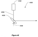
- a second laser may be positioned which emits a beam of visible light as illustrated in Figure 5.
- Figure 5 illustrates a system 500 including two coaxial lasers 502 and 504.
- the first laser 502 emits a beam of light (506 illustrated in solid line) eg. in the infrared portion of the EM spectrum and is used as the primary laser for particle detection.
- the second laser 504 emits a light beam 508 in the visible portion of the electromagnetic spectrum.
- This second laser can be mounted such that it is pre-aligned with the primary laser on an adjacent co-linear or co-axial path.
- the visible spot from this beam may be used to facilitate verification of the suitable positioning and alignment of the source.
- the second laser After commissioning the second laser can be turned off during normal operation. If the primary laser needs to be re-aligned after commissioning the visible light source can be turned back on.
- the same physical structure could be used to mount a short wavelength (blue or UV) laser to implement an embodiment of the system described above.
- this system will be provided with a reflective target onto which the beam from the light source is directed.
- the beam reflected from this target can then be used for determining the correct alignment of the laser beam and possibly for other tasks such as fractional light loss measurement.
- system may call for a mechanism for scanning the beam from the target to another point in order to monitor the region adjacent to the beam path for obstructions.
- the light source unit can be equipped with an optical detector, which is preferably directionally sensitive.
- the sensor is setup to track the alignment of the laser beam with respect to the light spot projected to the surface of the reflector.
- the detector can be used to measure fractional light loss and to track the location of the laser spot.
- Figure 6 illustrates an exemplary embodiment of a light source mounting arrangement 600 that enables both beam steering and spot tracking.
- the laser 602 emits a beam 604 that is steered by a electrically adjusting the angle of a movable mirror 606 in two rotational dimensions; for example, pitch and yaw.
- Alternative arrangements to achieve the same movement capability include the use of a plurality of mirrors each of which may tilt in only one dimension; or direct movement the laser emitter itself; or a combination of a movable emitter and one or more mirrors or prisms or the like.
- the optical receiver 608 views the laser spot 610 on the retro-reflective target 612 through the same movable mirror 606.
- the sensor 608 is mounted alongside the light source 602 and is aligned with it, such that the centre of its field of view 614 is centred substantially in line with the laser beam path 604.
- the optical receiver 608 consists of one or more photo-diodes mounted at the focal point of a lens mounted in a tube.
- a problem that can arise with detecting the location of the retro-reflective target e.g. after beam scanning or during commissioning is that other objects in the region may also give substantial reflections which may be mistaken for the wanted target, so forming "false targets".
- An example is the intersection of glass windows and a high gloss window frame, which may form an unintentional but very effective "corner reflector", that reflects the beam back along or very close to, the incident path.
- Such false targets may be distinguished from the wanted target in a number of ways. For example, by scanning the width and height of the reflective target to verify that these parameters, e.g. the extent of the target, are commensurate with the those expected for the real target.
- distinguishing features may be added to the real target; for example areas of reflective and non-reflective materials around the periphery, so that scanning the beam can create recognisable responses in a manner similar to a bar-code reader.
- distinguishing features may be added to the real target; for example areas of reflective and non-reflective materials around the periphery, so that scanning the beam can create recognisable responses in a manner similar to a bar-code reader.
- such methods may introduce undesirable complexities, ambiguities or delays in identifying the target.
- FIG. 7 illustrates another embodiment of the present invention generally similar to that of Figure 6 but which additionally includes a secondary light source that operates as a marker, in order to direct the laser beam correctly and quickly.
- the system 700 includes a secondary light source 702 that is preferably a LED emitting light at a wavelength to which the optical receiver 608 is sensitive.
- the light source 702 is mounted in a known positional relationship with respect to the target 612 and is preferably mounted on a sensor unit 704.
- the steerable mirror is adjusted to scan the laser from the target 612 to the sensors 704, during the search, the laser 602 may preferably be turned off and the secondary light source 702 is preferably modulated in a predetermined manner. This modulation is used in processing of the signal received by the sensor 608 to facilitate detection of the signal and to distinguish the wanted emitter 702 from any other unwanted light sources that may be present.
- a search pattern is used which minimises the time required to locate the centre of view of the optical detector 608, and laser beam 602, on the retro-reflective target 612; as follows.
- the mirror 606 is initially set to its centre position, and then caused to move in such a way that an increasingly large spiral shape is described by the laser beam movement.
- search patterns could readily be employed.
- the signal from the optical receiver 608 is processed to determine the mirror position at which the signal from the marker light source 702 mounted on the sensor 704 is maximised.
- the coordinates of the mirror 606 at that point are recorded as determining the location of the sensor unit 704.
- the position of the expected target 612 can be determined.
- the retro-reflective target 612 may be placed on the same horizontal line as the sensor's 704 inlet aperture at a displacement of 1 degree to the left.
- the mirror 606 is then aligned so that the laser is aimed at the expected position of the centre of the retro-reflective target 612 and the light source 602 is switched on and a similar search pattern begun. Theoretically this search should be begun with the laser centred on the retro-reflective target.
- the laser beam is modulated in a predetermined manner and the optical signal received by the optical receiver 608 from the reflected laser light is processed to determine the position at which the signal from the retro-reflective target 612 is maximised.
- the coordinates of the mirror 606 at that point are recorded as determining the location of the retro-reflective target 612.
- the remotely located mirror can be made to be scannable in addition to (or alternative to) using a scanning light source.
- the light source is mounted close to the camera, and has an associated laser target mounted on it (or adjacent to it).
- the laser can be scanned to locate the "smart' remote plane mirror (e.g. using the outward spiral pattern described above).
- the mirror can then be arranged to automatically be tilted and/or panned to place the reflected laser spot on target, as judged by a photo sensor on the laser.
- the scanning arrangement for the mirror need only allow slow movement to enable final alignment, whereas the laser can be allowed to perform quicker movement so as to enable it to scan for intruding objects from camera end as described herein.
- a transparency (or similar) can be used to simulate smoke for calibration or alignment of the system.
- a semi-transparent piece of light-scattering material may be advantageously used to determine the location of the laser beam path and to verify the correct operation of the particle detector. This is particularly valuable at commissioning and during maintenance.
- One method to avoid false alarms is to recognise the relatively sudden nature of an intrusion by a solid object compared to a smoke event. Instead of an alarm, a fault is raised in this case. While this method may be effective in some cases, for a scattered-light detector there remains a risk that an object will enter the beam at a rate that makes it substantially indistinguishable from smoke using this method alone.
- the current embodiment of the present invention provides an alternative, or complementary, solution to address this problem and aid in distinguishing such solid objects from smoke.
- the principle of operation is that the primary smoke detection beam is scanned in one or more axes; if the scattering signal received varies in a manner that is characteristic of a solid object, e.g. substantially fixed edges are identified, then the object is recognised as solid and reported as causing a fault rather than an alarm condition.
- a plurality of scans are made, as a solid object will tend to scatter light in a substantially consistent and repeated fashion, whereas a plume of smoke will vary significantly in both position and strength over a similar time period. For example, a scanning period of 5 to 20 seconds may be advantageously used.
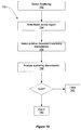
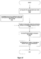
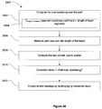
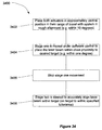
- Figure 7A is a flow chart illustrating such a method.
- the method 750 begins with the detection of scattered light by the AVSD system in step 752.
- the beam is scanned across the region of interest in a random or predetermined manner in step 754 in order to determine the manner in which the scattered light readings vary with beam position.
- a position dependent scattering characteristic of the scatterer is determined in step 756.
- the position dependent scattering characteristic may be the absolute scattering level or the rate of change of scattering or some other measure.
- the scattering characteristic is then analysed in step 758 to determine whether spatial variation of the scattering characteristic the object is solid-like or smoke-like. If the object is solid then a fault is raised at 760, and if the object is not solid an alarm signal may be raised at 762.
- the fault or alarm condition raised by this process may be delayed in accordance with time delays and threshold levels built into the alarm protocol of the smoke alarm system. Moreover, the determination whether an intrusion into the beam is solid or smoke can be made repeatedly within the appropriate delay period such that if an object initially appears to be the solid intrusion into the beam but later resembles smoke an appropriate alarm could be raised, and visa versa.
- the system can be used with a backscatter geometry, in such a system a difficulty may be encountered, in that the observing camera can be overloaded due to scattering (reflection) from a surface on which the beam impinges, e.g. a surface on which the beam is projected to observe the location beam. If this occurs, the overloading can cause a 'blooming' effect on the receiving image sensor, thus making part of its field of view ineffective.
- Figure 8 illustrates a particle detection system 800 according to an embodiment of the present invention.
- the system 800 includes a light source 802 that projects a beam 804, across a region being monitored.
- Particles entering the beam 804 cause light scattering, which is detected by the camera 806 to detect the presence of the particles. Additionally, when the beam 804 impinges on a wall 808 at the opposite side of the region being monitored a significant amount of scattering occurs at the spot 810 created. Because the spot 810 is within the field of view of the camera 806 and some of light scattered from the wall 812 is captured by the camera 806 this can result in part of the image sensor therein to be overloaded.
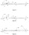
- FIG. 10A An arrangement for implementing such a method is shown in Figure 10A and the associated driving wave forms used in one embodiment are shown in Figure 10B .
- the arrangement 900 includes a phase controlled pulse generator 902, which is connected to two driver circuits 904 and 906 connected to the light source 908 eg. a laser diode and the light sensor arrangement 910 (e.g. camera) respectively.
- the light source 908 eg. a laser diode and the light sensor arrangement 910 (e.g. camera) respectively.
- Light is emitted from the laser diode 908 through the collimating lens 912. Part of the emitted beam 914 is reflected back as the return light 916.
- the returned light 916 first passes through focussing lens 918 before passing though micro-channel plate image intensifier 920, which has its operation controlled by the output pulse from the driver circuit 906.
- the amplified light beam 916 is then received at the CCD array of the light sensor 922.
- the source light intensity is modulated by the driver circuit 904 in such a way that after the beam has travelled to the target wall and been reflected back, it appears exactly out of phase with the modulated receiver sensitivity that is controlled by the driver circuit 906.
- Figure 10 shows three graphs 1050, 1060, 1070 requesting the emitted light intensity from the laser 908, the reflected light sensitivity received at the sensor and the sensor's sensitivity, respectively.
- the time taken for the light to travel from the source to the target wall and back to the sensor is indicated in Figure 10B as t r .
- the driving waveform 1050 for the laser diode 908 is modulated so that the round-trip time for the light pulse from the source, to the wall and back to the sensor coincides with reduced drive to the gated image intensifier 920 as shown in graph 1070.
- the camera will typically be mounted within a housing and the camera will view the area being monitored through a window in the housing.
- contamination of the camera and its housing may still be a problem faced by installations of the present invention.
- contamination e.g. dirt and dust accumulating on the detector optics.
- one problem that may cause rapid obscuration of the camera is an insect crawling on the camera housing window, which if it occurs, will interfere with the ability of the system to detect smoke. Therefore, it is advantageous to supervise the window surface so that a fault is signalled if the window is covered or partially obscured.
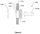
- FIG 11 illustrates a part of an imaging arrangement used in an embodiment of the present invention.
- the imaging arrangement 1100 includes an image capture array 1102 e.g. a CCD, which views the area being monitored via a focussing lens (or lenses) 1104. These optics are protected by a transparent window 1108. If an insect 1110 crawls across the window 1108 the performance of the system will be degraded.
- One method of checking for this type of obstruction is to illuminate the region of the window 1108 of the enclosure from time to time and check if the image captured differs substantially from a reference image known to be taken when the window is clear of obstructions, or predetermined threshold level.
- the imaging arrangement 1100 is provided with one or more light sources 1112 that are arranged to illuminate the surfaces of the window 1108. Any object close to or on the window 1108 will reflect a substantial portion of the illuminating light. An image captured under these conditions is compared with a reference image or threshold (taken without an obstruction) to determine if an obstruction on the window exists.
- the image taken with the light source 1112 "on" could be compared to a reference image taken with the light source 1112 off.
- the image with the light source 1112 turned on will include a bright artefact as a result of illuminating the obstruction.
- a similar technique can be used to detect insects or other obstructions on the inside of the window or on the surface of other optical components of the system, e.g. the image sensor lens.
- a fractional light loss measurement technique can be used to detect if there has been an intrusion into the laser beam path. If an intrusion is detected the system supervising the operation of the laser can be configured to reduce the laser power to a safe level until the intrusion is no longer present.
- the present inventors have devised a number of ways for detecting intrusion onto the beam based on fractional light loss.
- One method is to place an optical detector in the beam path and measure the intensity of the arriving laser radiation. This intensity measure can be input to the supervising system, and if a reduction in the received light is detected then it may be assumed that an intrusion is present.
- Figure 12 illustrates the light source portion 1200 of a system according to an embodiment of this aspect of the present invention.
- This arrangement includes a primary light source 1202, which will typically be a laser, that emits a beam of radiation 1204.
- This beam is reflected by a reflector, 1206 which is placed at the opposite side of the region being monitored.
- the light beam 1204 traverses the region and is reflected off the reflector 1206.
- the beam 1204 may be scattered and at least some of the reflected radiation 1208 will arrive at a suitably placed optical detector 1210.
- the reflector may be any of a variety of types, e.g. a corner cube type or a diffuse reflection surface or other retro-reflective material.
- the optical detector 1210 may be placed near the light source or at any other location where it is able to receive some reflected radiation.
- the detector 1210 If there is a change in the light level measured by the detector 1210 then it may indicate that something is obscuring the beam and as noted above the beam power can be reduced.
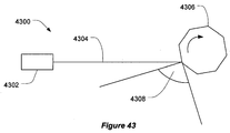
- a light source 1300 projects a beam 1302 in the direction of a reflective target 1304 in a manner described in previous embodiments. At least some of the reflected light 1306 is incident upon a receiver 1308 which is mounted adjacent to the light source 1300.
- the light source in this embodiment is mounted on a pan-tilt mechanism 1310 which has its position controlled by controller 1312 which adjusts the direction of the aforementioned beam in order to maximise the reflected light level received by receiver 1308.
- the system requires a method for initially aligning and then maintaining alignment over time.
- the following is a method for performing accurate alignment using the apparatus described above.
- the controller 1312 can cause the light source 1300 scan the beam 1302 over a region where the reflective target is likely to be, and stop when the received signal is above a pre-determined threshold.
- the pre-determined threshold can be a function of the distance.
- the edges can be detected.
- the laser 1300 is scanned over the target, and the positions at which the received signal is approximately half of the maxima are recorded. The laser is then set to the midpoint between these two positions. This process is then repeated in a direction orthogonal to the first, and can advantageously be repeated at least once more in the original direction. The repeated searches improve accuracy in cases where the target is not rectangular or its sides are not parallel to the search directions.
- a tilt sensor may be installed in at least one element of the system.
- a tilt sensor is mounted in the camera housing and can be used to indicate if the sensor has moved out of alignment.
- a tilt sensor in the light source housing can indicate if the light source has moved out of alignment.
- FIG. 14 which shows a housing arrangement 1400 that can hold either a light source or a receiver.
- the housing 1400 is generally speaking an enclosure in which the components forming either a light source or a receiver are housed, and an aperture 1402 (which may he enclosed by a window).
- the aperture 1402 can be used either as an exit window for a light source housed in the housing 1402 or a viewing window for a receiver housed therein.
- a tilt sensor 1404 is mounted in a fixed relationship with the housing 1400 e.g. by fixing means 1406.
- the output signals from the tilt sensor 1404 are processed by signal conditioning circuit 1408 and compared with preset acceptable readings to provide an error signal.
- a fault condition can be communicated to external monitoring equipment by a communication network e.g. via data cable 1410, or by other communications or signalling means such as a wireless communications link.
- the following supervision techniques can be applied to a range of AVSD system configurations, e.g. systems employing one or more light sources and/or one or more light sensors that perform smoke detection over different areas, using modifications that would be apparent to those skilled in the art.
- the light source 1500 and receiver 1502 are situated in close proximity to each other.
- the receiver 1502 is arranged to view a required area coincident with the path of the laser beam 1506.
- a reflector 1504, which may be a corner cube or other reflecting device is mounted at the opposing end of the area being monitored, and reflects the beam 1506 across the region being monitored in a direction such that the receiver 1502 can be used to detect forward scattering from the return path of the beam 1506 due to smoke or other particles.
- the light source 1500 is mounted on a scanning mechanism so that the beam may be scanned over an arc 1510. Any object e.g. 1512 , that is placed in the region bounded by the laser 1500, camera 1502 and reflector 1504 will be illuminated by the laser as it scans across it. Such illuminations may be detected by the camera and a fault raised.
- the same method can be applied.
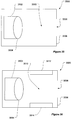
- FIG. 16 Another supervision method, which can be used in certain embodiments of the present invention, involves projecting light across the area being monitored and checking to see if a shadow is cast by any intruding objects.
- a system 1600 is illustrated in which this supervision method is implemented.
- a light source 1602 illuminates a region 1604 near a rearward facing camera 1606.
- an object eg. 1608 enters this region it casts a shadow 1610 on a background surface 1612 illuminated by the light source 1602.
- the output of the camera 1606 can be analysed to detect the shadow 1610 cast by the object 1608 and when a shadow is detected a fault can be raised.
- Either the same or an additional light emitter-receiver pair can be used for primary smoke detection purposes.
- a light source 1700 projects a beam 1702 over the region being monitored 1704.
- the beam 1702 preferably illuminates the whole region being monitored. If the beam 1702 is narrow this can be achieved by scanning the beam 1702 e.g. with a steerable mirror etc. across the region. Alternatively this can be achieve using a wider beam which covers the entire region of interest 1704.
- Light ray 1706 which may be due to a narrow steerable beam 1702 directed appropriately, or may be part of a wider beam, is coincident with an edge of intruding object 1708.
- a reflected glint 1710 from the edge of the object will be visible to receiver 1712.
- the output of the receiver 1712 can be analysed to determine the presence of such a glint, and if one is identified an error signal can be raised.
- a drawback of this method is that the region 1714 cannot be supervised, since light will be received by the receiver 1712 directly from the light source 1700. This will tend to overload the receiver's detection elements.
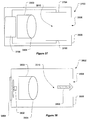
- a glint will also be visible due to refraction of light around an object.
- the light ray 1802 strikes the edge of the intruding object 1804 farthest from the camera 1712.
- the glint is visible to the detector 1712 by refraction.
- the intruding object 1708 would also be detectable by virtue of the fact that the light source 1702, is itself hidden from receiver 1712, and any light that would normally be visible to the sensor is now not observable.
- FIG. 19 One technique that can be used to supervise regions that are close to the light source in the sensor's field of view is to use a light source of sufficient physical size to cover otherwise unsupervised region, as illustrated in Figure 19 .
- the system of Figure 17 is augmented with a light bar 1902 mounted next to the light source 1700.
- an intruding object 1904 will block the receiver's 1712 view of part or all of the light bar 1902.
- the output of the receiver 1702 can be analysed and the intruding object detected and a fault raised.
- the triangle formed by the sensor 1712, and the edges of light bar 1902, enclose the majority of the previously unsupervised region.
- the remaining unsupervised region 1904 may be supervised by other methods, such as proximity detectors and other means known to those skilled in the art.
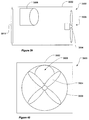
- a further supervision mechanism can use the background behind the beam to possibly detect intrusions into the region of interest.
- the sensor can be configured to detect variations in the background image to determine if an object has moved into the region of interest.
- this embodiment is similar to the method described above that uses a shadow to detect intrusions, but does not need an illumination beam to create changes in the background by way of a shadow.
- Such a system has the potential disadvantage that it may be difficult to determine if the changes observed in the backgrounds image have occurred between the beam and the camera i.e. in the region of interest, or if the changes were merely in the background areas where they have no effect of the systems detection capability.
- this ambiguity can be resolved by adding at least one more receiver observing substantially the same region of interest but from a different viewpoint. Using this arrangement it is relatively straight forward to calculate the position of a detected object in the field of view using the principles of geometry. The system can thereby differentiate benignly placed objects from those which may interfere with the systems ability to detect smoke.
- An additional problem with this method of background monitoring is that in dark environments it is possible that no background will be visible so it may not be possible to determine if an intruding object has been placed in the region of interest.
- One method of overcoming this problem is to employ active illumination so that at least some background features are always visible to the sensor when the region of interest is free from intruding objects.
- the background may be illuminated by invisible electromagnetic radiation, e.g. IR, emitted from a dedicated illumination light source, if the camera is sensitive to this wavelength radiation.
- the background regions may be populated with individual light sources such as, for example, LEDs or other small lamps whose light output is visible to the sensor. This is effectively a wide area light bar and can be implemented in line with the embodiments described above.
- a light may be projected on to part or all of the background that coincides with the sensor's view of the region of interest.
- This projected light may be in the form of a sheet of light which, when landing on a surface forms a stripe visible to the sensor, or it may be a beam or beams of light, either stationary or scanned over the background surfaces forming dots or multiple dots which are visible to the sensor; the presence of an intruding object in the field of view therefore causes a difference in the surface pattern as viewed by the sensor.
- the background may have projected upon it a pattern or patterns that are identifiable by the system and thus minimize the likelihood of an intruding object being interpreted as a background feature.
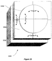
- Figure 23 illustrates an embodiment that uses a vertically scanning beam for supervision.
- the system 2300 includes a camera 2302 which has field of view 2304, in which a scanning light source 2306 resides.
- the beam from the light source can scan vertically over part of ceiling 2308 and part of wall 2310 that are visible to the camera 2302.
- the scanning light source 2306 is made to scan a region substantially overlapping field of view 2304 casting rays for example 2312. Other intermediate scan positions may be chosen depending on the requirements for size of object that must be detected.
- an intruding object 2314 that is introduced into the field of view masks the region 2316 from visibility to receiver 2302.
- Analysing the output of receiver 2302, in conjunction with known position of scanning light source 2306, reveals that in certain scan positions the camera 2302 will not view light on the wall or ceiling due to the masking effect of object 2314. In this case a fault condition can be raised.
- a light bar can also be used for supervision of the region of interest.
- Figure 21 illustrates a system 2100 of this type including a first light source 2102 and receiver 2104 configured to monitor a corresponding region of interest 2106.
- the system 2100 also includes a second light source 2112 and receiver 2114 configured to monitor a corresponding region of interest 2116.
- the system 2100 also includes two light bars 2108 and 2118.
- the light bars 2108 and 2118 are mounted between the first light source 2102 and the second receiver 2114, and between the second light source 2112 and the first receiver 2104.
- the task of intrusion detection may be therefore split in two, with each laser-receiver pair monitoring a different area in the region of interest.
- the triangular area, 2106 is monitored by the first receiver 2104 and first light bar 2108, which is achieved by the sensor 2104 checking for any change across the intensity profile of the light bar, which as noted above can be is interpreted being caused by an intruding object obscuring the light from light bar 2108.
- the triangular area 2116 is monitored by a second receiver 2114, and second light bar 2118.
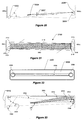
- FIG 22 illustrates an exemplary implementation of an apparatus 2200 that can be used in a preferred embodiment of this aspect of the present invention.
- the apparatus 2200 includes housing 2202 in which is mounted a combination of light source 2204, light bar 2206 and receiver 2208 that may be used at each end of system of the type illustrated in Figure 21 .
- the light source 2204 will be used to project a beam of light toward a similar device mounted at the opposing end of the system for the detection of light scatter by a receiver mounted at that end.
- a light source mounted at that opposing end will emit a beam of light toward the sensor 2208 for detection of particles by scattering from the beam.
- the light bar 2206 extends from the light source 2204 to the sensor 2208 and is used by the light sensor mounted at to opposite end of the system to supervise the region of interest as described above.
- the primary light source used for particle detection is a laser beam, and that it is at a wavelength which is of low, or zero, visibility to the human eye e.g. for aesthetic reasons.
- commonly available infra-red laser diodes with a wavelength in the region of 780nm may be advantageously used. These laser diodes provide a good compromise of relatively low cost and satisfactory small particle detection performance, and their visibility is low because they emit in a narrow band at a wavelength to which the human eye is very insensitive.
- a problem may arise as follows.
- one or more additional light sources may be required to support functions such as assisting in the determination of the location of the light source, targeting the laser beam and supervising the sensor field of view.
- a LED device can be used since laser diodes are comparatively expensive and require more supporting circuitry.
- LED devices may also be centred at the same wavelength as the primary light source, but in currently available technology they emit light in a broader range and have higher visibility to the human eye, which may be an aesthetic nuisance especially when used in low ambient light circumstances, such as in a theatre.
- LED alarm clocks are often equipped with a light sensor that causes the LED display to dim in a darkened room.
- embodiments of the present invention must address the problem of causing the 'ON' intensity of the LED devices to be reduced to a point where the nuisance effect of their visibility is substantially removed, while at the same time they remain sufficiently intense that the signal detected by the associated sensor is adequate for correct functionality.
- the LED can be in one of three possible states 'OFF', 'BRIGHT' or 'DIM'.
- the selection of the BRIGHT or DIM state is based on the measured ambient lighting intensity which is compared to a pre-determined threshold. To avoid unnecessary rapid changes between these the bright and dim states is a hysteresis is applied to the threshold.
- a plurality of intensity levels may be used, such that the intensity of the LED is maintained at a predetermined level sufficiently above ambient to reliably achieve the desired functionality, whilst minimising nuisance visibility.
- the ambient light level may be advantageously measured using optically sensitive components that already exist in the system for another primary function. This has the advantage of minimising component count, hence is beneficial to both cost and reliability.
- the ambient light level at the light source end may be monitored at the sensor end by measuring the intensity of pixels in the region of the LED position, or the intensity of pixels at the LED position when it is off.
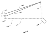
- Figure 20 illustrates an embodiment of the present invention using time of flight measurements to supervise the region of interest.
- a pulsed light source 2000 illuminates a region 2002 which includes intruding object 2004. Reflected light 2006 from object 2004, is returned to receiver 2008 that is located near the pulsed light source 2000.
- Timing circuitry (not shown) is used to control both the light source 2000 and the receiver 2008 and measures the round-trip time for a light pulse from the light source 2000 that is reflected by the object 2004 and returned to the sensor 2008. The distance to the object 2004 can then be determined by a simple calculation. Since the system knows the distance from the light source 2000, to the main system receiver 2002, a fault can be raised if the time of flight measurement indicates that an object is within in the intervening space.
- the system will be fitted with polarisation sensitive sensor such as a camera fitted with a polarising filter either external to the camera or built into the camera housing or optics.
- polarisation sensitive sensor such as a camera fitted with a polarising filter either external to the camera or built into the camera housing or optics.
- the face of the sensor could also be fitted with a polarising filter, or the sensor could have inherent polarisation sensitivity.
- the ratio of, detected light scattered by smoke particles to unwanted ambient light can be improved by a factor of about 2 by placing a polarising filter ahead of the camera and illuminating the monitored volume with a polarised light source.
- the polarisation of the light source and camera filter should be parallel aligned for optimum sensitivity. If the polarisation of either the source or the filter is rotated through 90 degrees, then only particles that modify the polarisation state of the incident light will be detected. In this case there will be a large reduction in sensitivity to small particles, since they do not tend to change the polarisation when they scatter light. However the response to large rough particles or non-specular surfaces will substantially remain. Thus a measure of very large particle density can be obtained.
- cross-polarised scattering coefficient will be the term given to measurements taken in an arrangement in which the polarisation of the light source and the sensor are perpendicular.
- the measurements taken in an arrangement with the polariser aligned with the light source polarisation will be referred to as the "parallel-polarised scattering coefficient”.
- the cross-polarised scattering coefficient can take different values depending on the following factors:
- the system can use this information to reposition the beam to a more advantageous position or positions away from obstructions.
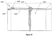
- Figure 24 illustrates a system 2400 capable of detecting both the cross polarised and parallel polarised scattering coefficients.
- the system includes at least one vertically polarised light source 2402 and at least one horizontally polarised light source 2404 which emit respective beams of light 2406 and 2408.
- the beams 2406 and 2408 are monitored by a sensor 2410, which in this case is a camera and on which is mounted vertically polarised filter 2412.
- a sensor 2410 which in this case is a camera and on which is mounted vertically polarised filter 2412.
- the parallel polarised scattering coefficient and cross polarised scattering coefficients respectively can be taken.
- the system would work with alternative polarisation arrangements.
- Figure 25 illustrates an alternative embodiment which can also be used to measure the parallel polarised and cross polarised coefficients in the system.
- a system 2500 which includes a single polarised light source 2502 which emits a beam 2504.
- the beam 2504 is monitored by a sensor 2506, which may be a video camera.
- the sensor 2506 is fitted with a polarising filter 2508 that can have its direction of polarisation controlled by a polarisation rotator 2510.
- the polarisation rotator 2510 can be of the liquid crystal type. It may also be a mechanical device configured to physically rotate the polarisation filter 2508.
- the polarisation filter may be fixed and the polarisation direction of the light source may be rotatable in order to project light in the first polarisation direction and a second polarisation direction.
- the system may be fitted with two cameras with polarising filters each set to monitor the light beam in different polarisation directions.
- double imaging may be employed by using a beam splitter to divide a beam into two to thereby present two identical images to the camera, but one via a parallel polariser and the other via a cross polariser.
- two of the AVSD systems can be arranged in close proximity each configured to operate in different polarisation orientations.
- Another variation is to use circular or elliptical polarisations.
- matching the filter and polarisation state of the light will allow scattered light from small particles to be received, and using a misaligned (preferably orthogonal) filter and light source polarisation state will reveal the scattered light from the larger, irregular particles.
- the image sequence captured can consist of interleaved normal, cross-polarised and off frames with the off frames used for background cancellation for both "on” measurements.
- a set of parallel-polarised and “off' frames can be captured, followed by set of cross-polarised and “off” frames, or any other sequence.
- the interleaved scheme is preferred because the two measurements are occurring closer together in time. Also, configurations that employ substantially the same beam path for the measurements are preferred because they avoid errors due to non-homogeneity of the particle density in the volume observed.
- cross-polarised frames can be used as if they were the off frames in the background cancellation techniques described in our co-pending application. Such a system can still usefully reject dust and large particles.
- This type of system can be advantageously employed in systems with dual cameras or double imaging since both the parallel-polarised and cross-polarised frames can be taken simultaneously.
- the two scattering measurements will be linear combinations of the parallel-polarised and cross-polarised values.
- the parallel-polarised and cross-polarised scattering coefficients may be computed provided the polarisation angles are known.
- a first method is to ignore the regions of space (i.e. those parts of the beam) with strong cross-polarised scattering response, as these indicate regions which are affected by large particles or objects, i.e. non-smoke particles.
- the system can be configured to generate fault conditions for action e.g. a call for service.
- the system can be configured to steer the beam away from the region.
- Fixed or adaptive thresholds and delays or other existing decision algorithms can be used to determine when to trigger a fault or steer the beam. This can be applied on a pixel-by-pixel basis along the beam, or on a sector or "virtual detector" basis.
- the cross-polarised scattering coefficients can be scaled and then subtracted from the parallel-polarised scattering coefficients.
- the resulting scattering data will now be predominantly from the small particles alone, and thus false alarms from dust etc will be reduced.
- the scaling factor is chosen to obtain adequate cancellation from typical nuisance particles such as dust clouds.
- a more elaborate data processing method is to compensate for the time varying particle size distribution of dust clouds.
- the particle size distribution will contain relatively more large particles when the cloud is first created compared to a time later on, due to gravitational separation of the dust particles.
- This can be modelled (for instance) with a fast-attack, slow-decay filter and scaling applied to the cross-polarised scattering response data.
- This filtered response can then be subtracted from the parallel-polarised scattering data to yield estimated scattering for the particles other than those in the dust cloud.
- the model can be further improved by allowing for diffusion effects.
- the alarm thresholds, delays or other decision parameters can be varied based on the strength of the cross-polarised scattering response data to reduce the probability of false alarm.
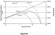
- the "fire" threshold is the smoke level at which the fire alarm is sounded and the fire brigade called.
- a smoke detector system can also have early warning or pre-alarms to warn of an impending fire condition. These pre-alarms do not normally have the same regulatory requirements as the fire alarm, so therefore it could be acceptable to not indicate a fault when these levels are modified to avoid a response to nuisance materials. Therefore, for some systems it may be sufficient to signal a fault condition only when the fire alarm threshold has needed to be raised to avoid a false alarm.
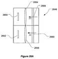
- Figure 26 shows an AVSD system 2600 to monitor a region 2602.
- AVSD systems are well suited to monitoring large open areas where a single beam can replace many conventional smoke detectors.
- the area being monitored 2602 may additionally include smaller adjoining spaces such as offices 2604, 2606, 2608 and 2610 that also require fire protection.
- One solution to this problem is to provide means to extract air from the adjoining spaces into the area protected by the AVSD system.
- each office 2604 to 2610 is provided with a respective fan 2612 to 2618 which is configured to pump air from the office into the AVSD monitored volume.
- the AVSD system 2600 is positioned within the volume 2602 in close proximity to the point of entry of the air from the other volumes.
- An embodiment of this type of system could be implemented to monitor a plurality of equipment cabinets by, for example, shining a beam of radiation across the top, or along the back of a row of cabinets. Other embodiments could also be used to monitor alcoves in tunnels.
- ducting could be used to transfer air from the sub-volumes into the main volume 2602.
- an AVSD system can be set up to monitor in a backscatter geometry rather than a forward scattering arrangement described in the majority of embodiments herein.
- These backscatter systems have an inherent advantage over forward scattering systems, in that the system's active (i.e. electrically powered) components all reside at the same end of the system. This clearly has advantages in terms of wiring and other aspects of installation
- backscatter systems have the disadvantage that they are often less sensitive than forward scattering geometries.
- measurements of the scattering properties of smoke has revealed that there is of the order of 100 times less light scattered back towards the source than is scattered forward in shallow angles of 1 to 20 degrees, resulting in almost a 100:1 loss of performance.
- a longer focal length lens may also be used to help recover the loss of spatial resolution.
- a problem with basic AVSD systems is that objects blocking the field of view of the camera can cause the system to fail to detect smoke.
- a fault condition if not accompanied by a fault or trouble signal from the smoke detector system is termed a critical fault or critical failure. It is a requirement that approved systems have a very low probability of critical failures.
- Another variation is to simply not use the scattering signal for producing the fire alarm.
- the scattering (preferably forward scatter) measurements are obtained by a camera to perform an early warning function, and to provide an indication of the location of the smoke.
- the smoke detection function i.e. the fire alarm signal that is used to call the fire brigade or to trigger suppression systems
- the smoke detection function is generated independently.
- the pre-alarm or early warning can be triggered using the laser that is already part of the AVSD system, by monitoring the laser power arriving at a target. This can be achieved in several ways, as described above, including using a photo-detector at the target, using a corner reflector or retro-reflector at the target and a photo-detector at the laser end.
- the beam power detected there is reduced the beam can be taken to be impeded effectively operating as a beam detector. This arrangement avoids the need for complex camera field of view supervision systems, while retaining most of the benefits of the AVSD system.
- a further variation is to use an independent smoke detection system such as an aspirated smoke detector e.g. such as those systems marketed under the trade mark VESDA by Xtralis Pty Ltd, to provide the approved smoke detection function for the building or area, and use one or more AVSD systems to provide early warning and smoke localisation functions.
- an independent smoke detection system such as an aspirated smoke detector e.g. such as those systems marketed under the trade mark VESDA by Xtralis Pty Ltd, to provide the approved smoke detection function for the building or area, and use one or more AVSD systems to provide early warning and smoke localisation functions.
- this positional change can be recognised by processing of the sensor output (e.g. video image) of the target spot or by accurately detecting the received light level at the targe spot, and looking for variations in received light level.
- Recognition of this heat shimmer mav advantageously be employed to identify fires from fuels which produce little or no smoke (e.g. ethyl alcohol); or such threats as overheating electrical or chemical processing equipment before a fire occurs.
- a more robust method is to take at least two images of the same scene at the same time but with different filtering means so that the two images taken have a different sensitivity to the radiation scattered from the beam.
- Such images may be processed by subtraction or other mathematical algorithms to substantially reject background movement, flicker or other variations while still providing sufficient sensitivity to the scattered light from the laser beam.
- Suitable filtering means can include wavelength filters where at least one filter is designed to pass the scattered laser light while at least one other is designed to pass light at another wavelength.
- a suitable set up for implementing this method is shown in Figure 26A .
- This figure illustrates a sensor 2648 system for an AVSD system including two image sensors 2650 and 2652 each sensor has a respective lens system 2654 and 2656 associated with it.
- the first sensor 2650 also has a filter 2658 configured to pass a first wavelength EM radiation, whilst the second sensor has a second filter 2660 adapted to allow EM radiation in a second wavelength band to pass.
- Another filtering arrangement similar to that of figure 26A uses polarising filters (instead or in addition to wavelength filters) in front of the image sensor elements so that at least one image sensor is sensitive to the same direction of polarisation as the light source while at least one other sensor is less sensitive than the first.
- a further embodiment combines two or more such filtered images onto one image sensor unit using mirrors or prisms or the like so that light passing through a first (preferably more sensitive) filter is directed to one portion of the imaging chip while at least one image having passed through the second (preferably less sensitive) filter is made to fall upon another part of the image chip.
- This arrangement has the advantage that two or more images may be recorded simultaneously with only one image sensing chip.
- Figure 26B shows an overview of the operation of this type of sensor system 2680, and Figure 26C shows the detail of the sensor arrangement 2682.
- the system 2680 includes a sensor arrangement 2682 which captures a double image on a common image sensor 2684. Some part of the light captured from the scene being monitored is reflected from mirror 2690 through lens 2692. This light (light ray A) then passes through filter 1, 2686 before being captured on a first part of sensor 2684. The light that is not reflected (light ray B) passes through the lens 2692 and then filter 2, 2688 before being captured on a second portion of the sensor 2684.
- the filters 2686 and 2688 can be either different polarising filters or wavelength filters to implement either of the methods described above. Alternatively one of the filters can be omitted and a filtered and un-filtered path can be obtained.
- the mirror is positioned, relative to the lens and image sensor, and aperture thorough which light arrives into the sensor system 2680, such that two images of the a substantially identical scene are captured.
- the background cancellation algorithm will typically take a sum or average over a number of "emitter on” image frames and “emitter off” image frames.
- the "emitter off' frames Prior to the subtraction of the "emitter off' frames from the “emitter on” frames, the “emitter off' frames are scaled by a factor, f, to compensate for variance in illumination levels of the "off" relative to the "on” images.
- the principle can be extended to allow for variations along the path, not just to either side of the path by subdividing the background areas 1 and 2 and region of interest (integration areas) into segments along the length of the beam path and performing the calculations for each subdivision.
- the segments can be made as narrow as the camera resolution allows.
- the background "scattering" level (or grey levels or smoke) computed from the background regions can be subtracted from the readings computed from the region of interest. This works on the principle that temporal lighting variations that cause small smoke readings will generally affect the background regions in a similar way to the region of interest (integration region). By performing the same calculations on background regions, an estimate of the errors produced in the integration area can be obtained and subtracted from the readings of the region of interest.
- the average of the two scattering values ( B 1 on - B 1 off ) and ( B 2 on - B 2 off ) obtained from the two background regions (1 and 2) are subtracted from the scattering values from the integration area ( I on -I off ).
- These calculations may be done using individual pixel values, raw grey levels integrated across the beam path, final smoke values or at any intermediate step, with varying degrees of computational effort.
- the background regions should preferably be chosen so as not to contain undesirable characteristics such as saturation, or localized flicker or noise. Individual pixels or areas may be excluded. In some cases usable pixels may only be present on one side of the integration area.
- the cancellation methods described here may still have an advantage over simple subtraction, namely that of cancelling out unwanted scattered light from the laser, which would otherwise lead to a constant "background" smoke reading in the absence of smoke.
- These background cancellation methods described cancel the unwanted scatter in the integration region, provided that the scatter in the integration region is approximately equal to the average of the scatter in the background regions. This condition is expected to be the case if the scatter was due primarily to non-specular reflections.
- Another method is to simply ignore (e.g. either zero or limit the values) those parts of the integration area where the corresponding "background scattering" is significant or excessive.
- the threshold at which this occurs could be related to, or derived from, the fire alarm threshold. The intention being to avoid false fire alarms. If a condition with elevated background scattering levels persists for an excessive length of time then a fault should be raised so the condition can be corrected.
- Systems with automatic beam steering, as described above, could attempt to self-correct by choosing a different beam position, before raising a fault.
- This property of large particles can be taken advantage of by implementing methods for recognizing the presence of dust, e.g. by detecting peaks in scattering relative to the prevailing time average, nearby spatial average, or both.
- the data samples used are background-cancelled, pixel wise grey level or scattering values.
- these filtering techniques can be performed on aggregate data such as an array of scatter vs. pixel radius.
- this example operates by the signal from each pixel in the integration area (after background cancellation) being compared with previous and/or subsequent samples.
- the value in question exceeds the average by a pre-determined threshold, it is ignored e.g. by clipping, discarding or replacing it with a local average.
- the calculated average may be obtained using a combination of samples captured before and after the sample being filtered.
- the signal from each pixel in the integration region (after background cancellation) can be compared with the average of adjacent pixels.
- the pixel value in question exceeds the mean by more than a pre-determined threshold, it can be ignored, e.g. by clipping or discarding it.
- This analysis can also be extended to allow rejection of short spatial runs or regions of excessive scattering. Since the beam length associated with a given pixel can vary greatly from one end of the beam to the other, it can be advantageous to vary the maximum allowed run length accordingly.
- the threshold can be determined as a multiple of the standard deviation of values from pixels near the pixel in question. Therefore the system will tend to respond to events that materially exceed the random noise from the system.
- Other thresholds either based on a statistical quantity associated with the system or an absolute or empirically determined parameter can also be used.
- Statistical analysis can also be used to discriminate between dust derived scattering signals and smoke derived signals.
- the inventors have determined that large particles tend to produce more temporal and spatial variation of the received scattered light than do small particles. Therefore, it is possible to correct scattering readings to compensate or at least partially compensate for the contribution due to dust or other large particles. Although many relationships or formulae could also be used, the preferred method is based on a mathematical model of the scattering contributions from dust and smoke.
- the model, and calculations that are performed are based on individual pixels or groups of nearby pixels with substantially similar statistics.
- the volume of interest is defined as the intersection of the laser beam and the field of view of the pixel or pixel group in question.
- ⁇ S itself comprised of contributions from the dust and smoke particle populations.
- ⁇ S 2 ⁇ 1 2 + ⁇ 2 2
- the method 2700 for correcting for dust can be implemented as illustrated in figure 27 , as follows:
- step 2704 the relative standard deviation ( R ) values for representative smokes and dusts for the particular system configuration can be established.
- R Dust should be greater than R Smoke since the particles are larger and cause more variation.
- the material used should be ones that produce the highest R-values for any smoke, and the lowest R-value for any dust. This is to avoid overcorrecting the readings and reducing the sensitivity to smoke in the presence of dust. Those skilled in the art will recognise opportunities to trade off dust rejection performance against smoke sensitivity and the risk of false negative decisions.
- ⁇ S ⁇ Total 2 ⁇ ⁇ Background 2
- the value of R should be substantially independent of particle concentration, so high concentrations (although not so high that secondary scattering is a problem) are best used to reduce the errors in measurement.
- R values may only be applicable for one pixel or region of pixels. This is because there can be considerable variations from pixel to pixel, e.g. due to the different length of the beam visible to pixels in different parts of the integration region.
- R values for smoke and dust need only be done once for a representative system. Once one set of R -values are established, corresponding values for non-identical systems could then be calculated or experimentally determined.
- the background noise level may vary with lighting conditions. So while it is possible to use a fixed value, it is better to use a value that depends on lighting conditions. This could be done by a formula, a look-up table or by measurements taken during conditions known to have a low concentration of scattering particles or by using the date from image frames taken without active illumination, i.e. "off frames".
- step 2706 the standard deviation ⁇ Total and mean S of sets of background-cancelled samples from each pixel are computed over short time periods (typically 1 to 10 seconds.)
- S A is a threshold at which no correction is to be performed and S B is a second threshold at which the correction is allowed to act fully, and are chosen so that system noise does not unduly affect the behaviour at any point.
- this process can be performed on the array of scatter vs. pixel radius, or other aggregate data.
- Another variation to this method that can be used involves a similar process, but which is applied to spatial rather than temporal variations in pixel value.
- a combination of samples obtained over time and space can be used to increase the total sample size. This reduces the estimation errors in the statistics resulting in better rejection of dust and more accurate smoke readings.
- Yet another variation involves taking advantage of the Gaussian scattering sample distribution that can arise with dust.
- a bright flash is produced. This is distinct from the random fluctuations caused by electrical noise processes or shot noise from the scene.
- the distribution of scattering readings in the absence of particles is approximately Gaussian since it is the sum of many uncorrelated sources.
- the distribution of scattering readings in the presence of detectable levels of small particles tend toward a Gaussian shape since there are typically large numbers of particles in the beam.
- the number of particles present will typically be far less than when smoke is present. Therefore the distribution may show some kurtosis and skew.
- the inventors have determined that a fat tail on the positive side of the distribution can be expected.
- skew or kurtosis may be used in a method similar to the above.
- the skew or (excess) kurtosis may be expected to be near zero for clean air or smoke, but be increasingly positive for increasing concentrations of dust.
- the skew or (excess) kurtosis may therefore be used to correct the scattering reading back to what it would have been without the dust.
- the basic AVSD system disclosed in our earlier patent applications measure smoke particle concentration vs. position along the laser beam. This data ultimately needs to be converted into a fire alarm signal or multiple signals, indicating the general location of the smoke, and the level of alarm. As will be appreciated by those skilled in the art a fire alarm system will typically have 2 early warning or pre-alarm levels, a fire alarm level for evacuation and calling the fire brigade and a fourth level to activate automatic suppression systems.)
- the relevant data available from the AVSD system as described in embodiments herein, and in our co-pending and previous patent applications includes an array of smoke concentration levels vs. an array index that represents the distance measured in pixels from the light source. Note that this choice of pixels is arbitrary, but was chosen since it substantially preserves the available resolution for subsequent processing steps.
- the segments corresponding to each virtual detector can be made to overlap to some extent. While this method is quite workable, it can result in excessive dilution if the segments are made too large, and excessive noise if they are made too small. For example, if a segment has a length of 5m along the beam, but the smoke plume is only 1 m across, the measured smoke density will be 5 times lower than actually exists in the plume. However, if small segments of 1 m lengths were employed the noise levels would be higher (due to less averaging), and the system would be less capable of detecting distributed smoke.
- a range of segments of different sizes are defined in step 2752.
- Each segment has a unique spatial length and position along the beam.
- the segments can overlap each other in small (or large) increments along the beam. Now, for any given smoke plume position and width, there will be a defined beam segment that is a good match for it which will yield the highest signal to noise ratio.
- Each segment so defined has an associated alarm decision logic (for example using the same threshold and delay scheme as previously employed).
- the alarm thresholds of each segment must be suitably scaled to take account of the differing noise levels that result from the different averaging lengths. (Otherwise false alarms will occur).
- a plurality of virtual detectors can be defined in step 2754 e.g. to correspond to detector addresses within a fire detection system to which the system belongs.
- each segment is associated with a virtual detector. This is can be done, for example, by finding the closest virtual detector location to the spatial centre of the segment.
- the alarm level for a given virtual detector is then calculated as the highest alarm level of all the segments associated with it.
- a smoke level for a virtual detector is computed to be the highest smoke level detected in all the segments associated with it. This smoke level is then passed to alarm decision logic that is associated with the virtual detector, rather than the segment.
- the higher noise levels that the narrow segments will exhibit can be handled by suitably scaling down the readings. This has the advantage of being able to track a drifting plume for the duration of alarm delays.
- a third, alternative is to compute an instantaneous alarm level for each segment e.g. compares smoke to an alarm threshold with no delay), then to pass the highest alarm level of any segment associated with a given virtual detector to alarm delay logic associated with the virtual detector.
- the segments have been described as effectively as windows or rectangular filters (i.e. equal weighting has been given to all included data points within the segments).
- Gaussian or other weighting schemes can also be used, and may show slightly improved correlation to typical smoke plumes.
- AVSD systems are well suited to use outside or in large open areas the affect of sunlight on the system must be considered. Typically sunlight can cause either saturation of the detector or reduced sensitivity (by introduction of noise) in an AVSD system.
- An additional way to avoid or at least ameliorate the affect sunlight or other stray light on an AVSD system is to carefully select the wavelength at which the AVSD system operates. More particularly the wavelength of the light emitter or light detection apparatus can be tuned to a wavelength that corresponds to either an atmospheric or solar spectral absorption line, for example there is a narrow absorption line in the solar absorption spectrum at about 656nm caused by Hydrogen which may be used.
- a suitable filter should be fitted to the camera that is centred on the absorption line, and preferably be not wider than the width of the line.
- the ultra-violet part of the electromagnetic spectrum can be advantageously employed. Wavelengths shorter than about 400nm are attenuated significantly by the earth's atmosphere and below 300nm the solar irradiance at ground level is attenuated by many orders of magnitude. This can be taken advantage of by using a Sub-300nm light source in an AVSD system. For example, a system with a laser wavelength of 266nm may not even require a narrow band filter, just a daylight blocking filter would be sufficient. Such a system may be capable of operation in full sunlight with little or no performance penalty.
- AVSD systems will preferably incorporate measures to reduce large particle sensitivity.
- One method uses the ratio of light scattered from the beam to fractional light loss. Lab tests have shown this ratio to be of the order of 30 (10 to 100) for dusts and around 1 to 2 for typical small particle cellulose smokes. Some smokes produced from hydrocarbons (n-heptane / toluene mix, and plastics) were found to produce a ratio of around 10, but still less than most dusts. These high-ratio smokes usually also produce at least 10 times more scattering than other smoke types, so a dust rejection method based on this ratio can also be used to correct the over-sensitivity to these smokes.
- the scattering levels detected can be corrected using the scattering to fractional light loss ratio, as follows:
- step 2806 the fractional light loss over the length of the beam is determined.
- step 2808 the ratio of fractional light loss to scatter is computed. This ratio is then raised to a chosen power, k, which is usually between 1 and 2 to determine a scattering correction factor in step 2810.
- the correction factor is used in step 2812 to correct the scattering derived smoke readings.
- the correction is performed by multiplying the smoke reading by the correction factor.
- the power k can be used to tune the degree of dust rejection desired. Although there is generally a trade off between dust rejection and the risk of reducing smoke responses, if k is set to a value of 1, this results in the scattering reading being corrected back to approximately the path loss system, which will always respond to smokes of any kind. Higher values of k may be used but create a risk of rejecting a genuine alarm condition. Other methods of using the relationship between scattering and fractional light loss ratio is an indicator of the type of scatterer (e.g. type of smoke, or smoke or dust etc.) being encountered may be devised.
- type of scatterer e.g. type of smoke, or smoke or dust etc.
- the fractional light loss measurement should be have about the same accuracy as the system sensitivity to scattering.
- the fractional light loss (with smoke) will be about 5%.
- the fractional light loss In order for the corrected smoke reading to not be in error by more than say 20%, the fractional light loss must be accurate to about 1%.
- the first method generally involves projecting a beam through the volume of interest (preferably the same beam as used for the scattering measurement), directly onto a photocell.
- the photocell can be fitted with wavelength and / or polarisation filters to reduce unwanted light.
- light-collecting optics may be employed allowing the use of a small cell with a large laser beam.
- the photocell or collecting optics In order to operate with suitable sensitivity the photocell or collecting optics must intercept the entire beam cross section. If it does not, then interference effects and small physical disturbances may cause fluctuations in the received laser power. Moreover the light collecting area of the sensor and/or optics must be sufficiently large to allow for alignment changes that may occur, e.g. movement caused by building movement and vibrations etc.
- the light collecting area must have a sufficiently uniform sensitivity across its area so that the whole beam is measured evenly.
- Figure 29A and 29B illustrate suitable systems for implementing the above mentioned techniques.
- Figure 29A illustrates a system 2900 having a light source 2902 which emits a beam of light 2904.
- the beam terminates on a photo-sensor 2906, which measures the received laser power.
- the photo-sensor 2906 has sensor area larger than the beam's 2904 cross section so that it can capture the entire beam reliably.
- the beam 2904 is monitored by a second light capturing device, e.g. a camera 2908, configured to monitor a field of view 2910 and send output signals for use in performing particle detection in a manner described elsewhere herein and in our earlier patent applications.
- a second light capturing device e.g. a camera 2908
- Figure 29B illustrates a system 2920 very similar to that of figure 29A (and like components have been like numbered), except that the beam of light 2904 emitted by the laser 2902 passes through imaging optics 2922 placed before the photo-sensor 2906.
- the imaging optics 1922 have a light gathering area larger than the beam's 2904 cross section so that it can capture the entire beam reliably and focus it onto the photo-sensor 2906. Because of the presence of the optics 2922, the size of the photo-sensor 2906 can be reduced.
- the beam 2904 is monitored by a second light capturing device, e.g. a camera 2908, configured to monitor a field of view 2910 and send output signals for use in performing particle detection in a manner described elsewhere herein and in our earlier patent applications
- the laser beam can be projected through the volume of interest (preferably the same beam as used for the scattering measurement) onto a reflective target.
- the power of the received reflected laser beam can be monitored at the laser end.
- the target is a specular retro-reflector e.g. a mirror corner cube or a carefully adjusted plane mirror, similar factors for ensuring optimal and steady light capture to those described in relation to the systems of figure 29A and 29B should be accounted for.
- the target is a non-specular reflector (eg, a rough surface of a retro-reflector composed of a large number of small reflectors) then there are different requirements for achieving high stability, since it is impractical for the photocell (or collecting optics) to intercept the return entire beam.
- FIG. 30 An example of a system implementing such a method is illustrated in figure 30 .
- the system is similar to that of figures 29A and 29B (and like components have been like numbered).
- the system differs from the previous embodiments in that the system 3000 includes a reflector, in this case a flat mirror 3002 that intersects the beam of light 2904 and reflects a return beam 3004.
- the return beam is received by a photo-sensor 3006 mounted next to the laser 2902.
- imaging optics may also be used with this embodiment.
- the beams 2904 and 3004 are monitored by a second light capturing device, e.g. a camera 2908 configured to monitor a field of view 2910, that sends output signals for use in performing particle detection in a manner described elsewhere herein and in our earlier patent applications
- the reflective target area and photo-sensor must be sufficiently large to allow for alignment changes that may occur with building movement etc.
- the reflective target's light receiving area must be sufficiently uniform in reflectivity.
- Laser "speckle” is an interference effect resulting from multi-pathing, i.e. a situation where light can travel from source to destination by different paths. In practice, this causes random bright and dark patches or a "speckle pattern" to appear in the beam's "spot".
- Suitable methods for reducing variations due to speckle are generally based on averaging a large number of uncorrelated speckle peaks and troughs.
- the inventors have devised the following exemplary techniques:
- Another method to increase the stability of the fractional light loss measurement is to re-set a 100% transmission reference level from time to time. This is preferably done whenever the scattering signal is below a threshold scattering level. Once the scattering signal is above some the threshold value the last calibration level is held and used for subsequent processing. However, as will be appreciated if a scattering level continues for an extended period of time the confidence in the reading will diminish as the time since last calibration will become long.
- embodiments of the present invention that that determine scattering ratios at multiple wavelengths.
- several light sources may be needed. These would preferably include one infra-red light source, and one shorter wavelength light source (e.g. blue/violet or UV) to distinguish particle sizes. This introduces the need for blue/violet or ultra-violet lasers that are currently still high cost, and typically have short-life expectancy and poor temperature tolerance.
- one shorter wavelength light source e.g. blue/violet or UV
- This approach will typically require selective filters at the light sensor, to enable one camera to view two wavelengths, or require an extra camera/filter pair.
- the background cancellation methods described in the previous embodiments include a process in which a number of emitter "on frames” and emitter “off frames” are summed or averaged. These methods typically use an equal number of ON and OFF frames.
- Figure 31 illustrates a series of frames of an image sequence 3100.
- Those frames coloured black represent "off' frames, i.e. those frames taken when the light source is turned off, and the frames shaded white are “on” frames” that are captured when the light source is illuminated.
- the sequence 3100 includes one more "off' frame than "on” frames. Meaning that the central time of the series of "on” frames is the same as that for the series of "off' frames.
- figure 31 illustrates a second series of image frames 3102.
- the first and last frame "off' frames can are weighted by a factor of one half when used in the averaging or summing. This allows the background-cancelled image to be the calculated as the sum of the ON frames minus the sum of the OFF frames, and avoiding the computational overhead of correcting for different numbers of frames.
- successive sequences of frames share (one or more frames) at their boundary.
- figure 32 shows three consecutively captured sequences of frames 3200, 3202 and 3204.
- the "off' frame at the boundary between adjacent frame sequences, 3200 and 3202; and 3202 and 3204 contributes to the averages or sums of "off frames" for each sequence as described above.
- steerable laser beams are used in embodiments of the invention to address the following problems :
- a range of laser beam-steering mechanism are known, and are used in a variety of applications. Examples known to the inventors include mirror galvanometers, piezo-electric optics mounts and motorised kinematic mounts.
- Examples known to the inventors include mirror galvanometers, piezo-electric optics mounts and motorised kinematic mounts.
- Range of movement A large range of movement may be needed in embodiments where beam scanning is used as part of ordinary operation.
- Rate of movement In some embodiments it may be necessary to compensate for vibrations or high speed movement in mountings of the system, therefore any beam steering mechanism used will need to be able to counter rapid variations in geometry.
- Service life Over the required service life of a particle detection system, which is expected to be ten years, a scan for the purposes of obstruction detection may occur at one minute intervals, totalling more than 5 million operations.
- Figure 33 illustrates schematically a first embodiment of the beam steering mechanism used in a preferred form of the present invention.
- the mechanism operates by changing the direction of a mirror mounted on the mechanism, although other optical components could be mounted thereon.
- the beam steering mechanism 3300 is advantageously made up from 2 or more stages mounted on top of each other.
- the first stage 3304 is steerable relative the mounting 3302, and provides coarse control over a large range of movement which is particularly useful for initial coarse alignment of the particle detection system at installation.
- the first stage can provide more than 40 degrees travel with an accuracy of, say ⁇ 1 degree.
- the second stage 3306 mounted on the first stage 3304 and independently steerable thereon, provides fine control over a narrower range of movement, which is useful for precise alignment during commissioning and for maintaining alignment in the event of drift. It may also permit repeated scanning of the laser beam for obstruction detection purposes without wearing out. Typically the second stage will provide a travel of less than 20 with accuracy of better than ⁇ 0.05 degrees.
- a first "coarse" stage 3304 can be mounted to the base mount 3302 and its directional control provided by using DC electric motors fitted with reduction gearboxes and a linkage mechanism, or cam, to a swash plate.
- DC electric motors fitted with reduction gearboxes and a linkage mechanism, or cam, to a swash plate.
- 2 motors are used, one controlling movement primarily in the X (horizontal) axis and one controlling movement primarily in the Y (vertical) axis.
- a second "fine" stage 3306 is mounted on the first stage 3304 and provides relatively precise movement using 2 electro-magnetic voice-coil actuators.
- Well known alternative actuators, such as the piezo-electric type, may be substituted.
- actuators chosen for the second stage such as voice-coils or piezo electric devices, do not to wear out in the same manner as other available actuator mechanisms.
- the steering mechanism just described can be used as follows for a target acquisition process used during commissioning of an AVSD system (or at other times, as illustrated in the flowchart of figure 34 .
- the target acquisition method 3400 begins (in step 3402) by the coarse positioning stage (and preferably also the fine positioning stage) being placed in its centralised position, which is preferably an un-powered rest position.
- the system is preferably then roughly aligned, say to within 10-20 degrees. This initial rough alignment will usually be performed manually by a technician, e.g. simply by relying on the installation measurements and relative pearliness of the walls to which the light source and target are mounted.
- step 3402 the coarse alignment stage is moved under software control to place the laser beam in rough proximity to the required target position, e.g. within 1 or 2 degrees.
- step 3404 the coarse alignment stage is then halted.
- the coarse alignment stage is constructed so that when power is removed it remains securely at rest.
- step 3404 the fine alignment stage is moved to steer the laser beam into the required position.
- the target acquisition algorithm used can be any of the acquisition algorithms described elsewhere in this document or any other mechanism known to those skilled in the art.
- a problem that may arise in an AVSD system is the contamination of the optically sensitive surfaces of the camera and laser by airborne particles. Such contamination may cause a reduction in the effective sensitivity and image resolution of the system. Whilst, the internal optical surfaces of the image capture device, light emitter or any intervening optical systems and may be sealed from the atmosphere to protect them, the outermost optical surfaces, e.g. lenses or windows are still prone to contamination.
- One way to prevent particles from contacting an exposed optically sensitive surface is to place the optically sensitive surface at a significant distance from the aperture in the enclosure through which it receives or transmits light.
- the aperture permits the entry of light into the camera, or the exit of a beam from the laser, but creates a pocket of substantially still air between the optical surface and the environmental atmosphere. Any dirt particles which enter the aperture will then be likely to settle out on optically unimportant surfaces before they travel to the optically sensitive surface. Furthermore, small particles which may otherwise stay suspended in the air and so could reach the optically sensitive surface can be removed.
- FIG 35 illustrates an optical arrangement 3500 of the type described above.
- the optical arrangement 3500 includes a component 3502 of the AVSD system (e.g. a light emitter such as a laser or light detector such as a camera) that includes an exposed optical element 3504, which may be a lens or window etc.
- a component 3502 of the AVSD system e.g. a light emitter such as a laser or light detector such as a camera
- an exposed optical element 3504 which may be a lens or window etc.
- a housing 3506 Surrounding this component 3502 is a housing 3506 which includes an aperture 3508 through which light may enter or leave the housing. Between the aperture 3508 and the exposed optical component 3504 the housing encloses a volume 3510 in which relatively still air will be present.
- One method for removing light particles suspended in the volume 3510 is to arrange for an electric field to be set up across the volume of air 3510, so drawing airborne particles from the air before they can travel to the optically sensitive surface.
- an electrical field is provided passively, by placing permanently electrically charged materials 3512 and 3514 adjacent to the air volume 3510.
- materials are well known and can include e.g. electret material such as that available from 3M or another polarised ferroelectric material.
- the construction of the housing 3506 is such that it allows the materials 3512 and 3514 to be conveniently replaced or cleaned, should it become excessively contaminated.
- the electric field can be generated actively e.g. by any one of several well known electronic methods.
- the housing 3506 includes two charged plates 3702 and 3704 located either side of the volume 3510.
- An electric field between the plates 3702 and 3704 are maintained by circuit 3706.
- the circuit can be, for example, an inverter/capacitor-diode ladder arrangement also known as a Cockcroft-Walton voltage multiplier.
- FIG. 38 illustrates an example of such an arrangement.
- the housing 3506 and optical components 3502 are the same as that illustrated in Figure 35 (and like components are like numbered).
- This arrangement 3800 additionally includes a fan 3802 mounted inside the housing 3506 which is arranged to draw air into the housing through the filter 3804. The clean air entering the housing in this manner is then forced around the optical components 3506 and exits the housing 3506 via the aperture 3508 in the direction of arrow 3806.
- This system can be enhanced by using a duct or other similar device to blow the clean air directly onto the exposed optically sensitive surface 3504 to ensure that it is kept free of contamination.
- a related, but slightly different problem may arise due to living creatures, particularly insects or spiders, moving onto the exposed optical surfaces of the system, e.g. on the lens the sensor or the laser emitter.
- An insect such as for example a large moth, could land on the sensor viewing window and obstruct an unacceptable portion of the view, or on a light source and could partly or fully obstruct the light beam emitted therefrom.
- spiders in particular may spin webs that can adhere to the optical surfaces and have a detrimental effect on performance of the system.
- An alternative protection method for the optics from encroachment by bugs or the like is to place an electrical conductor around the aperture in the housing or perimeter of the exposed optical component. This conductor can then be provided with a high-voltage power supply to electrocute any insect before it encroaches on the optics. To prevent potential for human injury, the current can be limited to non-harmful levels and operated with a safety interlock on the housing that turns off the high voltage supply if the hosing is opened.
- a predetermined threshold period for example 30 seconds
- an optical element's light path, or view is directed through at least a part of the envelope swept out by at least one moving member.
- This moving member prevents settling of an insect or other extraneous material on the optical surfaces.
- FIG 39 which illustrates an embodiment of a housing adapted to hold a camera.
- the housing arrangement 3900 is generally similar to that shown in figures 35 through 39 and accordingly elements that share the same function have been given the same reference numbers as in the previous embodiments.
- the system of figure 39 differs from the previous embodiments in that the housing 3902 is provided with a moving member in the form of a multi-bladed axial fan 3904 which is electrically driven. Fan is sized and positioned so that its blades largely fill the viewing aperture 3906 in the housing 3902 through which the camera 3504 captures light. In use the camera 3908 captures its images by looking through the blades of the spinning fan.
- the camera's 3908 open aperture time and the fan are preferably synchronised by software such that the camera 3908 captures each frame while the lens view is not obstructed by a fan blade.
- the fan motor is preferably of the DC brushless type and is equipped with a commutation output signal. Alternatively any one of many well known methods may be used to control or determine the speed and angular phase of the motor.
- any camera frames found to be obstructed by a fan blade can simply be discarded.
- the fan can be is arranged to draw air out of the housing 3902 in a manner consistent with the above described methods, thus inhibiting the entry of airborne dust etc. into the enclosure.
- the housing can be fitted with a filter 3910 to allow clean air to replace the air drawn out of the housing 3902 by the fan 3904.
- the fan 3904 may be run continually, or preferably to extend its life is operated only when an obstruction has already been detected. It may also be operated at intervals to test and maintain serviceability.
- the aperture 3906 may advantageously be partly obstructed, except in the region of the camera view, to limit air-flow rate.
- the moving member may be a wiper, a brush , a simple rod, or the like and may perform a reciprocating movement across the viewing hole to protect the optics from entry of insects, spider or other extraneous matter.
- the moving member may be caused to fully or partly rotate as it is moved across the hole, thus collecting the threads in a bobbin-like fashion.
- a cooling device such as a Peltier cooler is placed in close physical contact with the light sensor with heat energy being drawn away to an area for dissipation to the external environment.
- FIG 41 illustrates an image capturing arrangement made in accordance with an embodiment of this aspect of the present invention.
- the image capture arrangement 4100 includes an image capturing element 4102 e.g. a CCD or CMOS image capture chip mounted on a circuit board 4104.
- the image capturing element 4102 is configured to view the light source in the region of interest through imaging optics such as a lens 4106.
- Mounted to the opposite side of the circuit board 4104 to the imager capturing device 4102 is a Peltier cooling device 4108, which in turn is coupled to a heat sink 4110.
- the Peltier cooler 4108 transfers heat from the image capturing device 4102 to the heat sink 4110, where it is transferred to atmosphere.
- thermal insulation 4112 is provided.
- the system can incorporate a fan to force air circulation around the heat sink 4110.
- a heat pipe could be used to allow the heat sink to be placed further away from the image capture device 4102 to further aid heat dissipation.
- the previously described AVSD systems have used one or more stationary beams that illuminate fixed linear regions of interest across a volume being monitored.
- embodiments of the present invention could provide an effectively uninterrupted plane or planes of laser light directed across the space that can be monitored.
- This plane of light may be generated either by an optical system such as a cylindrical lens or by scanning one or more beams across the volume.
- Figure 42 illustrates an exemplary AVSD system of this type.
- the system 4200 is configured to monitor a room 4202 and includes a light source 4204 and an image capture means in the form of a camera 4206.
- the light source 4204 is illuminates a plane 4208 which is largely within the field of view of the camera 4206.
- the light source 4204 can illuminate a plane either by scanning a linear beam from side to side or by using optical focussing arrangements such as a cylindrical lens.
- FIG 43 illustrates an arrangement for beam scanning 4302 , including a light source 4302 that emits a beam of light 4304.
- the beam 4304 is reflected off a rotating octagonal mirror 4306.
- the mirror 4306 rotates the angle of incidence of the beam arriving at the mirror surface changes and the reflected beam sweeps out sector 4308.
- the system has the advantage of continually monitoring a larger area than a stationary beam, while allowing the use of simple and reliable mechanisms for beam scanning.
- the beam position in the camera's image will move. If the camera is in the same plane as the laser then the beam will be constrained to an epipolar line in the image, but the positional information will still be blurred because of the time varying geometry.
- the laser sweep is intentionally de-synchronized from the camera frame rate so that it sweeps out a set of different sub-area in each successive exposure period. After a time the cycle can repeat.
- the positional information can then be recovered from a set of such images by solving a set of simultaneous equations.
- the usual AVSD methods to obtain grey levels per pixel along the beam in the image are applied before attempting to de-convolve the blurring effect of the moving laser beam.
- the correct phase of the laser sweep vs. the camera shutter can be checked since a part of the sweep of the laser beam can be through the camera lens. Most of the time the laser can be blanked as it passes over the lens, and when a check is needed it can be left on. Laser Tilt adjustment can also be checked for in the same way (picturing the scanning to be occurring in the horizontal plane).
- Camera field of view supervision based on edge scattering as described above can also be performed with this physical arrangement.
- a light curtain can be created by scanning a beam using a rotating mirror placed at an angle to the beam.
- the mirror is set at 45 degrees to the direction of incidence of the beam and rotated about an axis parallel to the beam.
- a suitable arrangement 4500 is shown in figure 45 .
- the light source 4502 emits a beam of light 4504 toward a mirror 4506.
- the mirror 4506 is set at an angle of 45 degrees to the incident beam 4504 and reflects light at right angles to the direction of emission of the beam 4504 from the light source.
- the mirror 4506 is rotatable about an axis 4508 to cause the beam 4504 to sweep out a plane perpendicular to the incident beam 4504.
- the shape of the curtain of light swept out by the beam can be changed by changing the angle of incidence of the beam 4504 onto the mirror 4506.
- the beam can be made to sweep out a 3 dimensional volume.
- the mirror can be mounted in a gimballed type arrangement that allows movement about multiple axes.
- An alternative is to take advantage of the higher frame rate that short shutter times allow. By using the short shutter times more images can be captured in a given period, thus reducing the noise.
- the frame rate may by increased by N times. Therefore the integration lengths may be increased by the factor N. Assuming that the camera noise (in terms of pixel values) is unchanged, the extra averaging reduces the system noise by the factor N , while the gain change worsens by N times. The net result is then a noise level that is N times worse, but this is much better than being N times worse as would be the case without the frame rate increase.
- an exposure exceeding 2ms may cause saturation in environments with large amounts of sunlight. Therefore, for example, an exposure time of 2ms can be used, and this allows a frame rate of about 600 frames per second. Compared to operating the system at a more conventional rate of 25 fps, this would give a noise reduction and consequent sensitivity improvement of approximately a factor of 5.
- a method to allow operation at the high rate is to:
- the correct orientation can be achieved with a horizontal mounting orientation for the camera, and with the camera, laser and laser beam all within an approximately horizontal plane.
- the vertical height is one tenth of the full imager resolution, allowing up to a 10 times increase in frame rate.
- the effect of rising smoke levels on the received scatter signal is shown in the graph of figure 44 .
- the graph points are calculated on the basis of homogenous particle density in the volume of interest and with isotropically scattering, non-absorbing particles.
- the graph is plotted over two path lengths, 20 metres and 70 metres.
- the scatter signal follows the ideal response relatively well and increases in proportion to the obscuration.
- the scatter signal plateaus at a turnover point, and finally turns down.
- One method for avoiding the ambiguity is to use alarm thresholds that are sufficiently below the turnover point in the graph that an alarm will be issued before the smoke reaches the turnover point.
- the total fractional light loss along the beam length can be estimated from the average smoke level along the beam. This can then be used to scale up the scattering readings, since the path length for the photons is about the same whether they are scattered near the camera or near the laser or in between. These new scattering readings can then be fed back to improve the estimate of the total fractional light loss and the process repeated until the desired scattering accuracy is attained. However, it is important to check for convergence failure.
- a suitably large smoke level can be output in place of the non-convergent value, such that all down stream decision systems to go into alarm.
- a more sophisticated method is to model the path in small segments, using estimated fractional light loss for each segment based on the scattered light received for that segment. These values allow a better estimate of the total fractional light loss to be gained. Again iteration is necessary. Such 'finite element' methods are should be known to those skilled in the art.
- an additional detector capable of measurements at high smoke levels can be added to the system.
- the preferred method of correcting for the attenuation of the scattered light signal is to use the arrival intensity of the laser beam (which is equivalent to the fractional light loss) at the end of its path to determine an appropriate correction factor. This correction is most conveniently based on the primary AVSD laser. If one or more of the supervision techniques or targeting techniques described herein are employed any additional components required to implement such a method are likely to be present in the AVSD system. Alternatively the following arrangements could be used:
- the measured the arrival intensity of the laser beam may be combined with the scattering levels to more reliably detect particles.
- the system can be adapted to weight measurements between a scattering derived smoke signal and a smoke signal derived primarily from the arrival intensity of the laser beam.
- the bias between these different detection methods can be determined dynamically. For examine at low particle levels the system can be arranged to only use scattering derived smoke levels, however as the arrival intensity of the laser beam decreases more bias can be made toward a smoke level determined from the arrival intensity measurements.
- the system could be set up to scale the relative contribution of the two smoke measures between two thresholds.
- a measure of smoke determined from the received intensity measurement can be used.
- a weighted mean of the two can provide a smooth transition.
- An alternative method for allocating the intensity loss over the length of the beam to spatial sectors along the beam is to weight the allocation on the basis of the scattering signal, if it is sufficiently above the system noise level. In this way the ability of the AVSD system to determine the location of the smoke is not lost at high smoke levels.
Landscapes
- Physics & Mathematics (AREA)
- General Physics & Mathematics (AREA)
- Chemical & Material Sciences (AREA)
- Analytical Chemistry (AREA)
- Engineering & Computer Science (AREA)
- Life Sciences & Earth Sciences (AREA)
- Biochemistry (AREA)
- General Health & Medical Sciences (AREA)
- Health & Medical Sciences (AREA)
- Immunology (AREA)
- Pathology (AREA)
- Multimedia (AREA)
- Business, Economics & Management (AREA)
- Emergency Management (AREA)
- Computer Security & Cryptography (AREA)
- Dispersion Chemistry (AREA)
- Signal Processing (AREA)
- Investigating Or Analysing Materials By Optical Means (AREA)
Priority Applications (2)
| Application Number | Priority Date | Filing Date | Title |
|---|---|---|---|
| EP18152374.7A EP3367358A3 (en) | 2007-11-15 | 2008-11-14 | Particle detection |
| EP16161479.7A EP3082117B1 (en) | 2007-11-15 | 2008-11-14 | Particle detection |
Applications Claiming Priority (2)
| Application Number | Priority Date | Filing Date | Title |
|---|---|---|---|
| AU2007906260A AU2007906260A0 (en) | 2007-11-15 | Particle detection | |
| PCT/AU2008/001697 WO2009062256A1 (en) | 2007-11-15 | 2008-11-14 | Particle detection |
Related Child Applications (2)
| Application Number | Title | Priority Date | Filing Date |
|---|---|---|---|
| EP18152374.7A Division EP3367358A3 (en) | 2007-11-15 | 2008-11-14 | Particle detection |
| EP16161479.7A Division EP3082117B1 (en) | 2007-11-15 | 2008-11-14 | Particle detection |
Publications (3)
| Publication Number | Publication Date |
|---|---|
| EP2217911A1 EP2217911A1 (en) | 2010-08-18 |
| EP2217911A4 EP2217911A4 (en) | 2011-12-07 |
| EP2217911B1 true EP2217911B1 (en) | 2016-04-13 |
Family
ID=40638254
Family Applications (3)
| Application Number | Title | Priority Date | Filing Date |
|---|---|---|---|
| EP16161479.7A Active EP3082117B1 (en) | 2007-11-15 | 2008-11-14 | Particle detection |
| EP08849716.9A Active EP2217911B1 (en) | 2007-11-15 | 2008-11-14 | Particle detection |
| EP18152374.7A Withdrawn EP3367358A3 (en) | 2007-11-15 | 2008-11-14 | Particle detection |
Family Applications Before (1)
| Application Number | Title | Priority Date | Filing Date |
|---|---|---|---|
| EP16161479.7A Active EP3082117B1 (en) | 2007-11-15 | 2008-11-14 | Particle detection |
Family Applications After (1)
| Application Number | Title | Priority Date | Filing Date |
|---|---|---|---|
| EP18152374.7A Withdrawn EP3367358A3 (en) | 2007-11-15 | 2008-11-14 | Particle detection |
Country Status (10)
| Country | Link |
|---|---|
| US (4) | US9025144B2 (zh) |
| EP (3) | EP3082117B1 (zh) |
| JP (3) | JP5662154B2 (zh) |
| KR (3) | KR101705220B1 (zh) |
| CN (3) | CN101952709B (zh) |
| AU (1) | AU2008323626B2 (zh) |
| CA (3) | CA2993208C (zh) |
| HK (1) | HK1217807A1 (zh) |
| TW (3) | TWI583937B (zh) |
| WO (1) | WO2009062256A1 (zh) |
Families Citing this family (146)
| Publication number | Priority date | Publication date | Assignee | Title |
|---|---|---|---|---|
| AU2003902319A0 (en) | 2003-05-14 | 2003-05-29 | Garrett Thermal Systems Limited | Laser video detector |
| WO2006050570A1 (en) * | 2004-11-12 | 2006-05-18 | Vfs Technologies Limited | Particle detector, system and method |
| US9025144B2 (en) | 2007-11-15 | 2015-05-05 | Xtralis Technologies Ltd. | Particle detection |
| US8452052B2 (en) * | 2008-01-21 | 2013-05-28 | The Boeing Company | Modeling motion capture volumes with distance fields |
| EP2318804B1 (en) * | 2008-04-17 | 2017-03-29 | Shilat Optronics Ltd | Intrusion warning system |
| KR101851255B1 (ko) | 2008-06-10 | 2018-04-23 | 엑스트랄리스 테크놀로지 리미티드 | 입자 검출 |
| JP5185756B2 (ja) * | 2008-10-01 | 2013-04-17 | 川崎重工業株式会社 | 基板検出装置および方法 |
| CN104833655B (zh) * | 2009-05-01 | 2018-10-16 | 爱克斯崔里斯科技有限公司 | 微粒探测器的改进 |
| EP2452323B1 (en) * | 2009-07-07 | 2018-03-14 | Xtralis Technologies Ltd | Chamber condition |
| GB201003704D0 (en) * | 2010-03-05 | 2010-04-21 | Pcme Ltd | Apparatus and method for monitoring particles in a stack |
| EP2378270B1 (de) * | 2010-04-15 | 2015-06-24 | SICK Engineering GmbH | Verfahren zur Bestimmung einer Partikelkonzentration und Messvorrichtung |
| US8478529B2 (en) * | 2010-06-28 | 2013-07-02 | King Saud University | Visibility determination in environments containing airborne dust particles |
| US20130100135A1 (en) * | 2010-07-01 | 2013-04-25 | Thomson Licensing | Method of estimating diffusion of light |
| US20120120230A1 (en) * | 2010-11-17 | 2012-05-17 | Utah State University | Apparatus and Method for Small Scale Wind Mapping |
| US20130155672A1 (en) * | 2011-03-11 | 2013-06-20 | General Led, Inc. | Remote control track light fixture |
| EP2520169B1 (en) * | 2011-04-29 | 2019-12-04 | Electrolux Home Products Corporation N.V. | Baking oven door and baking oven |
| US8854426B2 (en) | 2011-11-07 | 2014-10-07 | Microsoft Corporation | Time-of-flight camera with guided light |
| JP5656131B2 (ja) * | 2012-02-13 | 2015-01-21 | 株式会社リコー | 撮像ユニット及びその設置方法 |
| CN102682293B (zh) * | 2012-05-14 | 2013-10-23 | 山东大学 | 基于图像的回旋体玻璃瓶凸点模具号识别方法及其系统 |
| KR20150027078A (ko) * | 2012-06-08 | 2015-03-11 | 엑스트랄리스 테크놀로지 리미티드 | 다중-모드 검출 |
| US9398229B2 (en) * | 2012-06-18 | 2016-07-19 | Microsoft Technology Licensing, Llc | Selective illumination of a region within a field of view |
| DE102012213125A1 (de) * | 2012-07-26 | 2014-01-30 | Robert Bosch Gmbh | Brandüberwachungssystem |
| US9575180B2 (en) * | 2012-09-13 | 2017-02-21 | Mbda Uk Limited | Room occupancy sensing apparatus and method |
| JP5998830B2 (ja) * | 2012-10-15 | 2016-09-28 | 富士ゼロックス株式会社 | 電力供給制御装置、画像処理装置、電力供給制御プログラム |
| KR20140088745A (ko) * | 2013-01-03 | 2014-07-11 | 삼성전기주식회사 | 파티클 검사 장치 |
| US9383478B2 (en) | 2013-01-25 | 2016-07-05 | The United States Of America, As Represented By The Secretary Of The Navy | System and method for atmospheric parameter enhancement |
| TWI490471B (zh) * | 2013-01-28 | 2015-07-01 | Univ Nat Taiwan | 非破壞性的複合材料檢測裝置及其檢測方法 |
| US20140217906A1 (en) * | 2013-02-01 | 2014-08-07 | Vung Van Vo | Remote Control Track Light Fixture |
| US9086273B1 (en) * | 2013-03-08 | 2015-07-21 | Google Inc. | Microrod compression of laser beam in combination with transmit lens |
| JP6523257B2 (ja) | 2013-06-03 | 2019-05-29 | ギャレット・サーマル・システムズ・リミテッドGarrett Thermal Systems Limited | 粒子検知システムおよび関連方法 |
| JP6186900B2 (ja) | 2013-06-04 | 2017-08-30 | ソニー株式会社 | 固体撮像装置、電子機器、レンズ制御方法、および撮像モジュール |
| RU2609746C2 (ru) * | 2013-06-10 | 2017-02-02 | Виктор Владимирович Холкин | Устройство контроля возникновения перемещения частей конструкций сооружения |
| CN103364949B (zh) * | 2013-07-24 | 2015-07-29 | 中海阳能源集团股份有限公司 | 自然风光热反射镜自清洁装置 |
| WO2015021428A1 (en) * | 2013-08-09 | 2015-02-12 | Cnry Inc. | System and methods for monitoring an environment |
| JP6359466B2 (ja) * | 2014-01-13 | 2018-07-18 | フェイスブック,インク. | サブ解像度での光学的検出 |
| DE102014001704B4 (de) * | 2014-02-08 | 2023-08-10 | Dräger Safety AG & Co. KGaA | Gasdetektionsvorrichtung |
| JP6438663B2 (ja) * | 2014-03-17 | 2018-12-19 | 三菱マテリアル株式会社 | 粉塵が存在する雰囲気中の物体の温度を計測する方法 |
| TWI556420B (zh) * | 2014-04-18 | 2016-11-01 | 光寶電子(廣州)有限公司 | 用於增加組裝平整度的影像擷取模組及其組裝方法 |
| US10140831B2 (en) | 2014-06-03 | 2018-11-27 | Carrier Corporation | Ionization air filters for hazardous particle detection |
| US10482740B2 (en) * | 2014-07-11 | 2019-11-19 | Carrier Corporation | Encoder-less lidar positioning technique for detection and alarm |
| US9677986B1 (en) * | 2014-09-24 | 2017-06-13 | Amazon Technologies, Inc. | Airborne particle detection with user device |
| DE102014223151A1 (de) * | 2014-11-13 | 2016-05-19 | Robert Bosch Gmbh | Partikelzähler |
| KR20160061492A (ko) * | 2014-11-21 | 2016-06-01 | 삼성디스플레이 주식회사 | 휴대용 먼지 센서 및 이를 이용한 휴대전화 |
| ES2721929T3 (es) * | 2014-12-01 | 2019-08-06 | Siemens Schweiz Ag | Detector de humo de luz dispersa con un diodo emisor de luz de dos colores |
| US10067234B2 (en) * | 2015-02-17 | 2018-09-04 | Honeywell International Inc. | Projected beam detector with imaging device |
| US10395498B2 (en) * | 2015-02-19 | 2019-08-27 | Smoke Detective, Llc | Fire detection apparatus utilizing a camera |
| CN104897538A (zh) * | 2015-06-16 | 2015-09-09 | 天津大学 | 一种基于数字全息术的工地扬尘检测装置 |
| CN106663357B (zh) * | 2015-06-23 | 2019-01-22 | 华中科技大学 | 一种基于双波长散射信号的气溶胶特征参数传感方法及其应用 |
| WO2017046832A1 (en) * | 2015-09-18 | 2017-03-23 | Hamamatsu Photonics K.K. | Optical distance measuring system |
| CN105181545A (zh) * | 2015-09-24 | 2015-12-23 | 青岛中特环保仪器有限公司 | 一种基于单摆原理的微重测量方法 |
| JP6864680B2 (ja) * | 2015-11-04 | 2021-04-28 | ノードソン コーポレーションNordson Corporation | ディスペンス流体の流体パターンを制御する方法及びシステム |
| CN105300851B (zh) * | 2015-11-11 | 2017-08-25 | 中国农业大学 | 一种基于激光技术的喷雾雾滴三维空间分布的检测方法 |
| US10049440B2 (en) * | 2015-12-28 | 2018-08-14 | Key Technology, Inc. | Object detection apparatus |
| US10254402B2 (en) * | 2016-02-04 | 2019-04-09 | Goodrich Corporation | Stereo range with lidar correction |
| US10161852B2 (en) * | 2016-02-08 | 2018-12-25 | MANTA Instruments, Inc. | Special purpose cuvette assembly and method for optical microscopy of nanoparticles in liquids |
| US10600057B2 (en) * | 2016-02-10 | 2020-03-24 | Kenexis Consulting Corporation | Evaluating a placement of optical fire detector(s) based on a plume model |
| EP3225977B1 (en) * | 2016-03-31 | 2019-03-13 | ams AG | Method and sensor system for detecting particles |
| CN105975066A (zh) * | 2016-04-28 | 2016-09-28 | 乐视控股(北京)有限公司 | 基于虚拟现实设备的控制方法及装置 |
| US9851291B2 (en) | 2016-05-02 | 2017-12-26 | Hamilton Associates, Inc. | Realtime optical method and system for detecting and classifying biological and non-biological particles |
| US10451518B2 (en) * | 2016-05-10 | 2019-10-22 | Rd2, Llc | All fiber temperature and air density sensor |
| JP6559346B2 (ja) * | 2016-06-13 | 2019-08-14 | シャープ株式会社 | 光電式ほこりセンサ装置および空調機器 |
| GB2551373B (en) * | 2016-06-16 | 2019-11-06 | Ffe Ltd | Beam alignment |
| US10261006B2 (en) * | 2016-07-21 | 2019-04-16 | Rosemount Aerospace, Inc. | Method of estimating cloud particle sizes using LIDAR ratio |
| TWI583982B (zh) * | 2016-09-26 | 2017-05-21 | 峰安車業股份有限公司 | 位移量測裝置及加工系統 |
| EP3309536A1 (en) * | 2016-10-11 | 2018-04-18 | Malvern Panalytical Limited | Particle characterisation instrument |
| CN106772422A (zh) * | 2016-10-25 | 2017-05-31 | 中国科学院合肥物质科学研究院 | 高空大气密度在线探测及计算方法 |
| JP7127052B2 (ja) | 2016-12-19 | 2022-08-29 | マサチューセッツ インスティテュート オブ テクノロジー | 大気粒子状物質を監視するためのシステムおよび方法 |
| CN106644867B (zh) * | 2016-12-30 | 2023-08-29 | 聚光科技(杭州)股份有限公司 | 气体中颗粒物的检测装置及方法 |
| US9983112B1 (en) * | 2017-01-20 | 2018-05-29 | Rosemount Aerospace Inc. | Controlled sampling volume of clouds for measuring cloud parameters |
| EP3382372A1 (en) * | 2017-03-27 | 2018-10-03 | Koninklijke Philips N.V. | Optical particle sensor and sensing method |
| US10393918B2 (en) | 2017-03-28 | 2019-08-27 | Banner Engineering Corp. | Retro-reflective sensor with multiple detectors |
| KR102436935B1 (ko) * | 2017-06-22 | 2022-08-26 | 삼성전자주식회사 | 빔 스티어링 장치 및 그 구동방법과, 빔 스티어링 장치를 포함하는 라이다 시스템 |
| US10168273B1 (en) * | 2017-07-01 | 2019-01-01 | Kla-Tencor Corporation | Methods and apparatus for polarizing reticle inspection |
| TWI651693B (zh) * | 2017-07-14 | 2019-02-21 | 元智大學 | 具有平行式雷射偵測器的巴士排煙系統及其運作方法 |
| CN109387460A (zh) * | 2017-08-14 | 2019-02-26 | 阅美测量系统(上海)有限公司 | 一种污染颗粒观察及测试装置及分析方法 |
| US10362296B2 (en) * | 2017-08-17 | 2019-07-23 | Microsoft Technology Licensing, Llc | Localized depth map generation |
| CN107504536B (zh) * | 2017-09-03 | 2019-05-24 | 浙江亿田智能厨电股份有限公司 | 一种具有反射式烟雾检测装置的油烟机及其控制方法 |
| US11195299B2 (en) * | 2017-09-12 | 2021-12-07 | Nec Corporation | Image processing device, image processing method and storage medium |
| WO2019164552A2 (en) | 2017-09-14 | 2019-08-29 | Brown University | Spatially resolved standoff trace chemical sensing using backwards transient absorption spectroscopy |
| US10320141B2 (en) | 2017-10-16 | 2019-06-11 | Rosemount Aerospace Inc. | Hard target detection for optical systems |
| CN107860691B (zh) * | 2017-10-17 | 2023-10-24 | 中国矿业大学(北京) | 一种基于机器视觉技术的激光矿井煤尘遥测方法 |
| TWI668673B (zh) * | 2017-11-14 | 2019-08-11 | 宏力實業股份有限公司 | Smoke detector structure |
| CN108205867B (zh) * | 2017-12-25 | 2021-03-09 | 中国科学技术大学 | 一种具备干扰粒子识别能力的早期火灾烟雾探测方法 |
| KR101944282B1 (ko) * | 2018-01-22 | 2019-01-31 | 주식회사 두리번테크 | 광섬유를 이용한 비상상황 모니터링 시스템 |
| JP7203500B2 (ja) * | 2018-03-13 | 2023-01-13 | 古河電気工業株式会社 | 火災煙検知装置 |
| US10439713B1 (en) * | 2018-03-15 | 2019-10-08 | The Boeing Company | System and method for receiving signal information for networking using a free space optical link |
| CN108982309A (zh) * | 2018-05-02 | 2018-12-11 | Oppo广东移动通信有限公司 | 检测方法、检测模组、电子装置、计算机设备和存储介质 |
| US11598722B2 (en) * | 2018-05-11 | 2023-03-07 | Carrier Corporation | Multi-point detection system |
| US11002836B2 (en) | 2018-05-14 | 2021-05-11 | Rockwell Automation Technologies, Inc. | Permutation of measuring capacitors in a time-of-flight sensor |
| US10996324B2 (en) | 2018-05-14 | 2021-05-04 | Rockwell Automation Technologies, Inc. | Time of flight system and method using multiple measuring sequences |
| US10969476B2 (en) | 2018-07-10 | 2021-04-06 | Rockwell Automation Technologies, Inc. | High dynamic range for sensing systems and methods |
| US11137331B2 (en) | 2018-08-21 | 2021-10-05 | Viavi Solutions Inc. | Multispectral sensor based alert condition detector |
| CN109117805B (zh) * | 2018-08-22 | 2022-04-29 | 浙江大丰实业股份有限公司 | 舞台灯光阵列防火控制系统 |
| RU2686401C1 (ru) * | 2018-09-20 | 2019-04-25 | федеральное государственное бюджетное образовательное учреждение высшего образования "Донской государственный технический университет" (ДГТУ) | Фотоэлектрический способ определения средней концентрации и среднего размера частиц пыли |
| RU2691978C1 (ru) * | 2018-09-20 | 2019-06-19 | федеральное государственное бюджетное образовательное учреждение высшего образования "Донской государственный технический университет" (ДГТУ) | Оптический пылемер |
| US10789506B2 (en) * | 2018-09-24 | 2020-09-29 | Rockwell Automation Technologies, Inc. | Object intrusion detection system and method |
| JP6764455B2 (ja) * | 2018-11-07 | 2020-09-30 | 新日本空調株式会社 | 粒子検知装置及び粒子検知方法 |
| JP7044042B2 (ja) * | 2018-11-30 | 2022-03-30 | 王子ホールディングス株式会社 | 微小浮遊物の測定装置、および、その測定システム |
| US10931874B2 (en) * | 2018-12-06 | 2021-02-23 | Flir Commercial Systems, Inc. | Burst mode calibration sensing and image mode sensing for imaging systems and methods |
| US10750645B2 (en) * | 2018-12-12 | 2020-08-18 | Texas Instruments Incorported | Transparent display panel cooling |
| KR20210117278A (ko) | 2018-12-24 | 2021-09-28 | 모바일 피직스 엘티디. | 표준 사용자 장비를 사용하는 공기중 미립자 밀도 결정 |
| KR102158927B1 (ko) * | 2019-01-09 | 2020-09-22 | 인천대학교 산학협력단 | 입자 측정 장치 |
| US11358184B2 (en) * | 2019-01-18 | 2022-06-14 | Johnson Controls Tyco IP Holdings LLP | Sensor system having transparent window contaminant removal using vibration |
| US11016024B2 (en) * | 2019-02-19 | 2021-05-25 | Kla Corporation | Air scattering standard for light scattering based optical instruments and tools |
| US11385338B2 (en) | 2019-03-06 | 2022-07-12 | Cnh Industrial America Llc | System and method for disregarding obscured sensor data during the performance of an agricultural operation |
| CN110057729A (zh) * | 2019-03-12 | 2019-07-26 | 天津大学 | 一种人体颗粒物被动沉降浓度测试方法 |
| CN110021135B (zh) * | 2019-03-13 | 2022-01-18 | 赛特威尔电子股份有限公司 | 一种明火报警检测方法、装置、烟雾报警器及存储介质 |
| JP6970703B2 (ja) * | 2019-03-18 | 2021-11-24 | 株式会社東芝 | 電子装置および方法 |
| KR102138222B1 (ko) * | 2019-04-11 | 2020-07-27 | 주식회사 제이에스티앤랩 | 배출가스 입자 측정 장치 |
| US11781238B2 (en) * | 2019-05-20 | 2023-10-10 | Applied Materials, Inc. | Systems and methods for plate-up detection |
| US11492967B2 (en) | 2019-07-03 | 2022-11-08 | Raytheon Technologies Corporation | Particulate ingestion sensor for gas turbine engines |
| CA3152982A1 (en) * | 2019-09-17 | 2021-03-25 | Carbon Autonomous Robotic Systems Inc. | Autonomous laser weed eradication |
| JP2023506759A (ja) | 2019-12-12 | 2023-02-20 | ブロリス センサー テクノロジー,ユーエイビー | ソリッドステートデバイス |
| CN113053057B (zh) * | 2019-12-26 | 2023-02-28 | 杭州海康微影传感科技有限公司 | 火点定位系统及方法 |
| US11348273B2 (en) * | 2020-02-25 | 2022-05-31 | Zebra Technologies Corporation | Data capture system |
| EP3889932B1 (en) * | 2020-03-30 | 2023-11-22 | Carrier Corporation | Beam smoke detector system |
| CN111467886B (zh) * | 2020-03-31 | 2021-11-19 | 苏州浪潮智能科技有限公司 | 一种火灾监控系统及集装箱式数据中心系统 |
| US11480530B2 (en) * | 2020-04-15 | 2022-10-25 | Rosemount Aerospace Inc. | Optical detection of foreign object debris ingested by aircraft engine |
| CN111551474A (zh) * | 2020-05-31 | 2020-08-18 | 天津大学 | 港口扬尘颗粒物浓度空间分布实测方法 |
| CN111650100A (zh) * | 2020-06-16 | 2020-09-11 | 辽东学院 | 一种基于Mie氏散射理论的颗粒粒度测量设备 |
| KR102357256B1 (ko) * | 2020-07-21 | 2022-02-07 | 한밭대학교 산학협력단 | 카메라의 임의 풍경 영상을 이용한 방향 의존 시정거리 및 2 차원 공간 미세먼지 분포 측정 방법 |
| CN114061907A (zh) * | 2020-07-29 | 2022-02-18 | 合肥维信诺科技有限公司 | 光晕量化系统及方法 |
| US11828879B2 (en) | 2020-07-29 | 2023-11-28 | Lg Innotek Co., Ltd. | Vibrated polarizing beam splitter for improved return light detection |
| US11521882B2 (en) | 2020-08-20 | 2022-12-06 | Taiwan Semiconductor Manufacturing Company, Ltd. | Wafer notch positioning detection |
| CN112284987A (zh) * | 2020-09-01 | 2021-01-29 | 华电(印尼)玻雅发电公司 | 一种煤粉细度测量系统 |
| DE102020213162A1 (de) * | 2020-10-19 | 2022-04-21 | Robert Bosch Gesellschaft mit beschränkter Haftung | Optoelektronisches System, LiDAR-System und Verfahren zum Reinigen eines Innenraums eines optoelektronischen Systems |
| US11726035B2 (en) * | 2020-12-11 | 2023-08-15 | Raytheon Technologies Corporation | Terahertz enhanced foreign object debris discrimination for optical particulate sensor |
| IT202000032021A1 (it) * | 2020-12-23 | 2021-03-23 | Universita’ Degli Studi Di Modena E Reggio Emilia | Metodo per valutare il rischio di contaminazione ambientale da agenti patogeni diffusi per via aerea, in locali chiusi provvisti di impianti HVAC |
| CN112954152A (zh) * | 2020-12-30 | 2021-06-11 | 神思电子技术股份有限公司 | 一种激光摄像机消除光反射的系统及方法 |
| KR102506418B1 (ko) * | 2021-01-29 | 2023-03-06 | 에스피티씨주식회사 | 굴뚝 먼지 측정기 |
| DE102021205061A1 (de) * | 2021-05-19 | 2022-11-24 | Robert Bosch Gesellschaft mit beschränkter Haftung | Verfahren und Vorrichtung zum Ermitteln verdeckter Objekte in einer ein Umfeld repräsentierenden 3D-Punktwolke |
| CN113310851B (zh) * | 2021-05-25 | 2023-08-15 | 清华大学深圳国际研究生院 | 一种实时浑浊介质目标识别系统和方法 |
| US20230009165A1 (en) * | 2021-07-07 | 2023-01-12 | Sidewalk Labs LLC | Wireless occupancy sensors and methods for using the same |
| WO2023028194A1 (en) * | 2021-08-25 | 2023-03-02 | Industrial Intelligence, Inc. | System, device and method for effective deployment of a dust accumulation sensor |
| CN113739913B (zh) * | 2021-08-27 | 2022-03-11 | 长春理工大学 | 一种智能化透雾霾光学成像探测装置及其使用方法 |
| CN113552056B (zh) * | 2021-09-17 | 2022-01-21 | 中国电器科学研究院股份有限公司 | 一种湿热海洋环境模拟设备及其辐照强度预测方法 |
| CN113702597B (zh) * | 2021-09-18 | 2024-05-03 | 烟台伟昌电子材料有限公司 | 一种室内空气质量检测仪及其检测方法 |
| US11657692B1 (en) | 2021-10-28 | 2023-05-23 | Honeywell International Inc. | Smoke detector |
| US11551535B1 (en) * | 2021-10-28 | 2023-01-10 | Honeywell International Inc. | Operating a scanning smoke detector |
| CN114544440B (zh) * | 2022-02-22 | 2024-01-12 | 安徽理工大学 | 一种截割产尘实验系统及其截割产尘监测方法 |
| CN114324098B (zh) * | 2022-03-10 | 2022-05-24 | 南京波瑞自动化科技有限公司 | 一种双光路激光前向散射颗粒物浓度测量装置 |
| US20230411024A1 (en) * | 2022-06-21 | 2023-12-21 | X-Energy, Llc | System and method for making nuclear fuel elements with a controlled number of nuclear particles |
| US11961381B2 (en) | 2022-06-21 | 2024-04-16 | The Adt Security Corporation | Life safety device with machine learning based analytics |
| CN114979587B (zh) * | 2022-07-29 | 2022-11-04 | 四川锦美环保股份有限公司 | 一种共享涂装线调度管理控制系统 |
| CN115096768A (zh) * | 2022-08-24 | 2022-09-23 | 浙江省水利水电勘测设计院有限责任公司 | 可同时测量颗粒粒径与体积浓度的背光成像系统和方法 |
| CN117282200B (zh) * | 2023-11-25 | 2024-02-02 | 甘肃第四建设集团有限责任公司 | 建筑施工降尘控制方法及系统 |
Citations (2)
| Publication number | Priority date | Publication date | Assignee | Title |
|---|---|---|---|---|
| EP1300816A1 (de) * | 2001-10-04 | 2003-04-09 | VIDAIR Aktiengesellschaft | Verfahren und System zur Erkennung von Bränden in Räumen |
| GB2426323A (en) * | 2005-05-16 | 2006-11-22 | Fire Fighting Entpr Ltd | Infra-red beam smoke detection system |
Family Cites Families (84)
| Publication number | Priority date | Publication date | Assignee | Title |
|---|---|---|---|---|
| US3429243A (en) * | 1965-08-16 | 1969-02-25 | Polaroid Corp | Exposure value compensator |
| US3688298A (en) * | 1970-05-13 | 1972-08-29 | Security Systems Inc | Property protection system employing laser light |
| US3788742A (en) * | 1971-06-24 | 1974-01-29 | Westinghouse Electric Corp | Gas monitoring system |
| US3737858A (en) * | 1971-07-13 | 1973-06-05 | Advanced Research Corp | Versatile telemetering system |
| US3727056A (en) * | 1972-03-03 | 1973-04-10 | Electro Signal Lab | Photon couplers with solid state lamps |
| US3924252A (en) * | 1973-03-15 | 1975-12-02 | Espey Mfg & Electronics Corp | Laser smoke detection |
| CH574117A5 (zh) * | 1973-10-24 | 1976-03-31 | Sick Erwin Fa | |
| US3901602A (en) * | 1974-05-13 | 1975-08-26 | Us Commerce | Light scattering method and apparatus for the chemical characterization of particulate matter |
| CH600456A5 (zh) | 1976-12-23 | 1978-06-15 | Cerberus Ag | |
| JPS5483491A (en) * | 1977-12-15 | 1979-07-03 | Matsushita Electric Ind Co Ltd | Smoke detector |
| JPS5622932A (en) | 1979-08-02 | 1981-03-04 | Matsushita Electric Ind Co Ltd | Adjusting method for sensitivity of photoelectric smoke detector |
| JPS58214995A (ja) * | 1982-06-08 | 1983-12-14 | 能美防災株式会社 | 火災報知設備 |
| JPS61182419A (ja) | 1985-02-08 | 1986-08-15 | Nissan Motor Co Ltd | 過給機付エンジンのインタク−ラ装置 |
| JPS62153780A (ja) | 1985-12-27 | 1987-07-08 | Kyoritsu Denpa Kk | インタ−レ−ス表示装置 |
| DE3641716A1 (de) * | 1986-12-06 | 1988-06-16 | Palas Gmbh | Verfahren und vorrichtung zum untersuchen einer partikel enthaltenden stroemung |
| JPH03188596A (ja) * | 1989-12-19 | 1991-08-16 | Nittan Co Ltd | 煙濃度監視方式 |
| JPH03245296A (ja) | 1990-02-23 | 1991-10-31 | Oki Denki Bosai Kk | 煙感知器の試験方法及び煙感知器 |
| JP2935549B2 (ja) * | 1990-08-23 | 1999-08-16 | 能美防災株式会社 | 火災検出方法及び装置 |
| US5266798A (en) * | 1990-09-14 | 1993-11-30 | High Yield Technology | High sensitivity, large detection area particle sensor for vacuum applications |
| CH683464A5 (de) * | 1991-09-06 | 1994-03-15 | Cerberus Ag | Optischer Rauchmelder mit aktiver Ueberwachung. |
| JPH06109631A (ja) | 1991-10-31 | 1994-04-22 | Hochiki Corp | 火災報知装置 |
| JPH05288668A (ja) | 1992-04-13 | 1993-11-02 | Anelva Corp | 塵検出器 |
| US5502434A (en) * | 1992-05-29 | 1996-03-26 | Hockiki Kabushiki Kaisha | Smoke sensor |
| US5651047A (en) * | 1993-01-25 | 1997-07-22 | Cardiac Mariners, Incorporated | Maneuverable and locateable catheters |
| JPH06288917A (ja) * | 1993-03-31 | 1994-10-18 | Nohmi Bosai Ltd | 煙式火災感知器 |
| JP3251763B2 (ja) | 1993-04-30 | 2002-01-28 | ホーチキ株式会社 | 火災報知装置及び火災検出方法 |
| US5576697A (en) * | 1993-04-30 | 1996-11-19 | Hochiki Kabushiki Kaisha | Fire alarm system |
| US5521366A (en) * | 1994-07-26 | 1996-05-28 | Metanetics Corporation | Dataform readers having controlled and overlapped exposure integration periods |
| AU719048B2 (en) | 1995-04-06 | 2000-05-04 | Alfa Laval Agri Ab | Method and apparatus for quantitative particle determination in fluids |
| DE19520488C1 (de) * | 1995-06-03 | 1996-09-05 | Draegerwerk Ag | Meßvorrichtung zur Infrarotabsorption |
| WO1997001925A1 (en) * | 1995-06-26 | 1997-01-16 | Phase One Denmark A/S | Digital camera image recording method and system |
| US6550949B1 (en) * | 1996-06-13 | 2003-04-22 | Gentex Corporation | Systems and components for enhancing rear vision from a vehicle |
| JPH10154284A (ja) | 1996-11-22 | 1998-06-09 | Harumi Takeda | 煙感知システム |
| JP2956653B2 (ja) | 1996-12-16 | 1999-10-04 | 日本電気株式会社 | パーティクルモニター装置 |
| JP3032485B2 (ja) * | 1997-05-29 | 2000-04-17 | ホーチキ株式会社 | 光電式煙感知器の投光装置 |
| JP3588535B2 (ja) * | 1997-06-30 | 2004-11-10 | ホーチキ株式会社 | 煙感知装置 |
| US5912619A (en) * | 1997-12-31 | 1999-06-15 | Wells Fargo Alarm Systems, Inc. | Security system using optical sensors |
| US6119055A (en) * | 1998-01-23 | 2000-09-12 | Mcdonnell Douglas Corporation | Real time imaging system and method for use in aiding a landing operation of an aircraft in obscured weather conditions |
| JP4038878B2 (ja) | 1998-05-26 | 2008-01-30 | 松下電工株式会社 | 画像処理を用いた火災検出装置 |
| JP3996272B2 (ja) * | 1998-06-29 | 2007-10-24 | 新日本空調株式会社 | エアロゾル検出方法 |
| US6288644B1 (en) * | 1998-09-01 | 2001-09-11 | Caretaker System, Inc. | Perimeter monitoring system |
| JP3724689B2 (ja) * | 1998-10-30 | 2005-12-07 | ホーチキ株式会社 | 火災監視装置及び火災感知器 |
| JP2000180349A (ja) | 1998-12-10 | 2000-06-30 | Daido Steel Co Ltd | 煤塵等の監視装置 |
| US6091345A (en) * | 1998-12-10 | 2000-07-18 | The United States Of America As Represented By The Administrator Of The National Aeronautics And Space Administration | Synchronized target subsystem for automated docking systems |
| US6292683B1 (en) * | 1999-05-18 | 2001-09-18 | General Electric Company | Method and apparatus for tracking motion in MR images |
| US6700484B2 (en) * | 1999-12-30 | 2004-03-02 | Texas Instruments Incorporated | Networked miniature chemical optical sensors |
| DE10046992C1 (de) * | 2000-09-22 | 2002-06-06 | Bosch Gmbh Robert | Streulichtrauchmelder |
| GB0028162D0 (en) * | 2000-11-20 | 2001-01-03 | Sentec Ltd | Distributed image processing technology and services |
| JP2002223019A (ja) * | 2001-01-24 | 2002-08-09 | Rion Co Ltd | レーザ発振器とそれを用いた光散乱式粒子検出器 |
| JP4132692B2 (ja) * | 2001-02-20 | 2008-08-13 | 株式会社堀場製作所 | 粒径分布測定装置 |
| JP5115912B2 (ja) * | 2001-02-23 | 2013-01-09 | 独立行政法人日本原子力研究開発機構 | 高速ゲート掃引型3次元レーザーレーダー装置 |
| EP1239433A1 (de) * | 2001-03-09 | 2002-09-11 | VIDAIR Aktiengesellschaft | Verfahren und Vorrichtung zur Detektion von Rauch und/oder Feuer in Räumen |
| DE10118913B4 (de) * | 2001-04-19 | 2006-01-12 | Robert Bosch Gmbh | Streulichtrauchmelder |
| JP3350528B2 (ja) | 2001-05-16 | 2002-11-25 | 株式会社半導体エネルギー研究所 | アクティブマトリクス型表示装置 |
| US6958689B2 (en) * | 2001-09-21 | 2005-10-25 | Rosemount Aerospace Inc. | Multi-sensor fire detector with reduced false alarm performance |
| JP2004056713A (ja) * | 2002-07-24 | 2004-02-19 | Sharp Corp | 撮影部を有した携帯機器および露出調整装置 |
| JP2004112034A (ja) * | 2002-09-13 | 2004-04-08 | Canon Inc | 撮像装置 |
| EP1546783A1 (en) * | 2002-09-27 | 2005-06-29 | Koninklijke Philips Electronics N.V. | Optical element, method for manufacturing such an element and a method for aligning a light beam and such an element |
| DE10246056A1 (de) * | 2002-10-02 | 2004-04-22 | Robert Bosch Gmbh | Rauchmelder |
| JP2004144512A (ja) * | 2002-10-22 | 2004-05-20 | Denso Corp | 乗員検知システム |
| JP2004257876A (ja) * | 2003-02-26 | 2004-09-16 | Toshiba Ceramics Co Ltd | 気中パーティクルの可視化方法 |
| AU2003902319A0 (en) * | 2003-05-14 | 2003-05-29 | Garrett Thermal Systems Limited | Laser video detector |
| GB0323055D0 (en) * | 2003-10-02 | 2003-11-05 | Unidata Europ Ltd | Particulate detector |
| KR20070093153A (ko) * | 2003-10-23 | 2007-09-17 | 테렌스 콜 마틴 | 하우징을 덕트 위에 마운팅하기 위한 방법 |
| US7746239B2 (en) * | 2003-11-17 | 2010-06-29 | Hochiki Corporation | Light scattering type smoke detector |
| US20070242269A1 (en) * | 2004-03-06 | 2007-10-18 | Michael Trainer | Methods and apparatus for determining characteristics of particles |
| US20050207655A1 (en) * | 2004-03-22 | 2005-09-22 | Nasreen Chopra | Inspection system and method for providing feedback |
| GB0407327D0 (en) | 2004-03-31 | 2004-05-05 | Vaulted Image Technologies Ltd | Cameras |
| JP4652716B2 (ja) * | 2004-04-21 | 2011-03-16 | ニッタン株式会社 | 煙感知器 |
| PL368774A1 (en) | 2004-06-25 | 2005-12-27 | Artur Kozioł | Method and sales point terminal for effecting payments through the gsm mobile telephone network (or other networks, such as the umts) |
| KR200363865Y1 (ko) * | 2004-07-12 | 2004-10-11 | (주)니즈 | 입자의 크기 및 종류 구분이 가능한 파티클 센서 |
| WO2006050570A1 (en) * | 2004-11-12 | 2006-05-18 | Vfs Technologies Limited | Particle detector, system and method |
| US8502870B2 (en) * | 2005-02-02 | 2013-08-06 | Pima Electronic Systems Ltd. | Device, system, and method of rapid image acquisition |
| CN100427922C (zh) * | 2005-07-22 | 2008-10-22 | 公安部沈阳消防研究所 | 一种烟雾浓度探测装置 |
| JP2007163894A (ja) * | 2005-12-14 | 2007-06-28 | Fujifilm Corp | 液晶表示装置 |
| JP2007212860A (ja) * | 2006-02-10 | 2007-08-23 | Fujifilm Corp | 積層体の製造方法、積層体、液晶表示装置用基板、液晶表示素子及び液晶表示装置 |
| US7423277B2 (en) * | 2006-03-14 | 2008-09-09 | Axcelis Technologies, Inc. | Ion beam monitoring in an ion implanter using an imaging device |
| US9025144B2 (en) | 2007-11-15 | 2015-05-05 | Xtralis Technologies Ltd. | Particle detection |
| JP5324598B2 (ja) * | 2007-12-04 | 2013-10-23 | パーティクル・メージャーリング・システムズ・インコーポレーテッド | 非直角粒子検出システム及び方法 |
| KR101851255B1 (ko) * | 2008-06-10 | 2018-04-23 | 엑스트랄리스 테크놀로지 리미티드 | 입자 검출 |
| CN104833655B (zh) * | 2009-05-01 | 2018-10-16 | 爱克斯崔里斯科技有限公司 | 微粒探测器的改进 |
| JP4994422B2 (ja) * | 2009-05-13 | 2012-08-08 | リズム時計工業株式会社 | 検知システム、検知システムの信号処理方法、および、煙感知器 |
| WO2011151821A1 (en) * | 2010-05-31 | 2011-12-08 | Dvp Technologies Ltd. | Inspection of region of interest |
| DE102012210035A1 (de) * | 2012-06-14 | 2013-05-23 | Carl Zeiss Smt Gmbh | EUV-Lithographieanlage und Verfahren zum Detektieren von Partikeln in einer EUV-Lithographieanlage |
-
2008
- 2008-11-14 US US12/743,171 patent/US9025144B2/en active Active
- 2008-11-14 KR KR1020167013836A patent/KR101705220B1/ko active IP Right Grant
- 2008-11-14 EP EP16161479.7A patent/EP3082117B1/en active Active
- 2008-11-14 CA CA2993208A patent/CA2993208C/en active Active
- 2008-11-14 CN CN200880124826.1A patent/CN101952709B/zh active Active
- 2008-11-14 AU AU2008323626A patent/AU2008323626B2/en not_active Ceased
- 2008-11-14 EP EP08849716.9A patent/EP2217911B1/en active Active
- 2008-11-14 KR KR1020107013180A patent/KR101658581B1/ko active IP Right Grant
- 2008-11-14 WO PCT/AU2008/001697 patent/WO2009062256A1/en active Application Filing
- 2008-11-14 CN CN201810904511.4A patent/CN109255924A/zh active Pending
- 2008-11-14 CA CA2705830A patent/CA2705830C/en active Active
- 2008-11-14 CN CN201510280542.3A patent/CN105185026B/zh active Active
- 2008-11-14 TW TW104103916A patent/TWI583937B/zh not_active IP Right Cessation
- 2008-11-14 CA CA3103407A patent/CA3103407A1/en active Pending
- 2008-11-14 TW TW106104269A patent/TWI654418B/zh not_active IP Right Cessation
- 2008-11-14 TW TW097144146A patent/TWI481846B/zh not_active IP Right Cessation
- 2008-11-14 JP JP2010533384A patent/JP5662154B2/ja not_active Expired - Fee Related
- 2008-11-14 KR KR1020177003007A patent/KR101913287B1/ko active IP Right Grant
- 2008-11-14 EP EP18152374.7A patent/EP3367358A3/en not_active Withdrawn
-
2014
- 2014-07-18 JP JP2014148142A patent/JP6030092B2/ja not_active Expired - Fee Related
-
2015
- 2015-04-16 US US14/687,969 patent/US9702803B2/en active Active
-
2016
- 2016-05-20 HK HK16105796.7A patent/HK1217807A1/zh not_active IP Right Cessation
- 2016-07-22 JP JP2016144362A patent/JP6523220B2/ja active Active
-
2017
- 2017-06-07 US US15/616,429 patent/US10429289B2/en active Active
-
2019
- 2019-10-01 US US16/590,116 patent/US20200056973A1/en not_active Abandoned
Patent Citations (2)
| Publication number | Priority date | Publication date | Assignee | Title |
|---|---|---|---|---|
| EP1300816A1 (de) * | 2001-10-04 | 2003-04-09 | VIDAIR Aktiengesellschaft | Verfahren und System zur Erkennung von Bränden in Räumen |
| GB2426323A (en) * | 2005-05-16 | 2006-11-22 | Fire Fighting Entpr Ltd | Infra-red beam smoke detection system |
Also Published As
Similar Documents
| Publication | Publication Date | Title |
|---|---|---|
| US10429289B2 (en) | Particle detection | |
| CA2965635C (en) | Particle detector, system and method | |
| AU2018282480B2 (en) | Particle detection |
Legal Events
| Date | Code | Title | Description |
|---|---|---|---|
| PUAI | Public reference made under article 153(3) epc to a published international application that has entered the european phase |
Free format text: ORIGINAL CODE: 0009012 |
|
| 17P | Request for examination filed |
Effective date: 20100615 |
|
| AK | Designated contracting states |
Kind code of ref document: A1 Designated state(s): AT BE BG CH CY CZ DE DK EE ES FI FR GB GR HR HU IE IS IT LI LT LU LV MC MT NL NO PL PT RO SE SI SK TR |
|
| AX | Request for extension of the european patent |
Extension state: AL BA MK RS |
|
| DAX | Request for extension of the european patent (deleted) | ||
| A4 | Supplementary search report drawn up and despatched |
Effective date: 20111108 |
|
| RIC1 | Information provided on ipc code assigned before grant |
Ipc: G01N 21/53 20060101AFI20111103BHEP Ipc: G08B 17/107 20060101ALI20111103BHEP |
|
| 17Q | First examination report despatched |
Effective date: 20130613 |
|
| 111Z | Information provided on other rights and legal means of execution |
Free format text: AT BE BG CH CY CZ DE DK EE ES FI FR GB GR HR HU IE IS IT LT LU LV MC MT NL NO PL PT RO SE SI SK TR Effective date: 20131218 |
|
| GRAP | Despatch of communication of intention to grant a patent |
Free format text: ORIGINAL CODE: EPIDOSNIGR1 |
|
| INTG | Intention to grant announced |
Effective date: 20151015 |
|
| GRAS | Grant fee paid |
Free format text: ORIGINAL CODE: EPIDOSNIGR3 |
|
| GRAA | (expected) grant |
Free format text: ORIGINAL CODE: 0009210 |
|
| AK | Designated contracting states |
Kind code of ref document: B1 Designated state(s): AT BE BG CH CY CZ DE DK EE ES FI FR GB GR HR HU IE IS IT LI LT LU LV MC MT NL NO PL PT RO SE SI SK TR |
|
| REG | Reference to a national code |
Ref country code: GB Ref legal event code: FG4D |
|
| REG | Reference to a national code |
Ref country code: AT Ref legal event code: REF Ref document number: 790660 Country of ref document: AT Kind code of ref document: T Effective date: 20160415 Ref country code: CH Ref legal event code: EP |
|
| RIN2 | Information on inventor provided after grant (corrected) |
Inventor name: AJAY, KEMAL Inventor name: COOPER, KATE Inventor name: KNOX, RON |
|
| REG | Reference to a national code |
Ref country code: IE Ref legal event code: FG4D |
|
| REG | Reference to a national code |
Ref country code: DE Ref legal event code: R096 Ref document number: 602008043621 Country of ref document: DE |
|
| REG | Reference to a national code |
Ref country code: LT Ref legal event code: MG4D |
|
| REG | Reference to a national code |
Ref country code: AT Ref legal event code: MK05 Ref document number: 790660 Country of ref document: AT Kind code of ref document: T Effective date: 20160413 |
|
| REG | Reference to a national code |
Ref country code: NL Ref legal event code: MP Effective date: 20160413 |
|
| PG25 | Lapsed in a contracting state [announced via postgrant information from national office to epo] |
Ref country code: NL Free format text: LAPSE BECAUSE OF FAILURE TO SUBMIT A TRANSLATION OF THE DESCRIPTION OR TO PAY THE FEE WITHIN THE PRESCRIBED TIME-LIMIT Effective date: 20160413 Ref country code: FI Free format text: LAPSE BECAUSE OF FAILURE TO SUBMIT A TRANSLATION OF THE DESCRIPTION OR TO PAY THE FEE WITHIN THE PRESCRIBED TIME-LIMIT Effective date: 20160413 Ref country code: PL Free format text: LAPSE BECAUSE OF FAILURE TO SUBMIT A TRANSLATION OF THE DESCRIPTION OR TO PAY THE FEE WITHIN THE PRESCRIBED TIME-LIMIT Effective date: 20160413 Ref country code: LT Free format text: LAPSE BECAUSE OF FAILURE TO SUBMIT A TRANSLATION OF THE DESCRIPTION OR TO PAY THE FEE WITHIN THE PRESCRIBED TIME-LIMIT Effective date: 20160413 Ref country code: NO Free format text: LAPSE BECAUSE OF FAILURE TO SUBMIT A TRANSLATION OF THE DESCRIPTION OR TO PAY THE FEE WITHIN THE PRESCRIBED TIME-LIMIT Effective date: 20160713 |
|
| REG | Reference to a national code |
Ref country code: FR Ref legal event code: PLFP Year of fee payment: 9 |
|
| PG25 | Lapsed in a contracting state [announced via postgrant information from national office to epo] |
Ref country code: GR Free format text: LAPSE BECAUSE OF FAILURE TO SUBMIT A TRANSLATION OF THE DESCRIPTION OR TO PAY THE FEE WITHIN THE PRESCRIBED TIME-LIMIT Effective date: 20160714 Ref country code: LV Free format text: LAPSE BECAUSE OF FAILURE TO SUBMIT A TRANSLATION OF THE DESCRIPTION OR TO PAY THE FEE WITHIN THE PRESCRIBED TIME-LIMIT Effective date: 20160413 Ref country code: AT Free format text: LAPSE BECAUSE OF FAILURE TO SUBMIT A TRANSLATION OF THE DESCRIPTION OR TO PAY THE FEE WITHIN THE PRESCRIBED TIME-LIMIT Effective date: 20160413 Ref country code: HR Free format text: LAPSE BECAUSE OF FAILURE TO SUBMIT A TRANSLATION OF THE DESCRIPTION OR TO PAY THE FEE WITHIN THE PRESCRIBED TIME-LIMIT Effective date: 20160413 Ref country code: ES Free format text: LAPSE BECAUSE OF FAILURE TO SUBMIT A TRANSLATION OF THE DESCRIPTION OR TO PAY THE FEE WITHIN THE PRESCRIBED TIME-LIMIT Effective date: 20160413 Ref country code: PT Free format text: LAPSE BECAUSE OF FAILURE TO SUBMIT A TRANSLATION OF THE DESCRIPTION OR TO PAY THE FEE WITHIN THE PRESCRIBED TIME-LIMIT Effective date: 20160816 Ref country code: SE Free format text: LAPSE BECAUSE OF FAILURE TO SUBMIT A TRANSLATION OF THE DESCRIPTION OR TO PAY THE FEE WITHIN THE PRESCRIBED TIME-LIMIT Effective date: 20160413 |
|
| PG25 | Lapsed in a contracting state [announced via postgrant information from national office to epo] |
Ref country code: IT Free format text: LAPSE BECAUSE OF FAILURE TO SUBMIT A TRANSLATION OF THE DESCRIPTION OR TO PAY THE FEE WITHIN THE PRESCRIBED TIME-LIMIT Effective date: 20160413 Ref country code: BE Free format text: LAPSE BECAUSE OF FAILURE TO SUBMIT A TRANSLATION OF THE DESCRIPTION OR TO PAY THE FEE WITHIN THE PRESCRIBED TIME-LIMIT Effective date: 20160413 |
|
| REG | Reference to a national code |
Ref country code: DE Ref legal event code: R097 Ref document number: 602008043621 Country of ref document: DE |
|
| PG25 | Lapsed in a contracting state [announced via postgrant information from national office to epo] |
Ref country code: CZ Free format text: LAPSE BECAUSE OF FAILURE TO SUBMIT A TRANSLATION OF THE DESCRIPTION OR TO PAY THE FEE WITHIN THE PRESCRIBED TIME-LIMIT Effective date: 20160413 Ref country code: SK Free format text: LAPSE BECAUSE OF FAILURE TO SUBMIT A TRANSLATION OF THE DESCRIPTION OR TO PAY THE FEE WITHIN THE PRESCRIBED TIME-LIMIT Effective date: 20160413 Ref country code: RO Free format text: LAPSE BECAUSE OF FAILURE TO SUBMIT A TRANSLATION OF THE DESCRIPTION OR TO PAY THE FEE WITHIN THE PRESCRIBED TIME-LIMIT Effective date: 20160413 Ref country code: DK Free format text: LAPSE BECAUSE OF FAILURE TO SUBMIT A TRANSLATION OF THE DESCRIPTION OR TO PAY THE FEE WITHIN THE PRESCRIBED TIME-LIMIT Effective date: 20160413 Ref country code: EE Free format text: LAPSE BECAUSE OF FAILURE TO SUBMIT A TRANSLATION OF THE DESCRIPTION OR TO PAY THE FEE WITHIN THE PRESCRIBED TIME-LIMIT Effective date: 20160413 |
|
| PLBE | No opposition filed within time limit |
Free format text: ORIGINAL CODE: 0009261 |
|
| STAA | Information on the status of an ep patent application or granted ep patent |
Free format text: STATUS: NO OPPOSITION FILED WITHIN TIME LIMIT |
|
| 26N | No opposition filed |
Effective date: 20170116 |
|
| REG | Reference to a national code |
Ref country code: DE Ref legal event code: R081 Ref document number: 602008043621 Country of ref document: DE Owner name: GARRETT THERMAL SYSTEMS LTD., BRACKNELL, GB Free format text: FORMER OWNER: XTRALIS TECHNOLOGIES LTD, NASSAU, BS |
|
| PG25 | Lapsed in a contracting state [announced via postgrant information from national office to epo] |
Ref country code: SI Free format text: LAPSE BECAUSE OF FAILURE TO SUBMIT A TRANSLATION OF THE DESCRIPTION OR TO PAY THE FEE WITHIN THE PRESCRIBED TIME-LIMIT Effective date: 20160413 |
|
| PG25 | Lapsed in a contracting state [announced via postgrant information from national office to epo] |
Ref country code: LU Free format text: LAPSE BECAUSE OF NON-PAYMENT OF DUE FEES Effective date: 20161130 |
|
| REG | Reference to a national code |
Ref country code: FR Ref legal event code: PLFP Year of fee payment: 10 |
|
| PG25 | Lapsed in a contracting state [announced via postgrant information from national office to epo] |
Ref country code: CY Free format text: LAPSE BECAUSE OF FAILURE TO SUBMIT A TRANSLATION OF THE DESCRIPTION OR TO PAY THE FEE WITHIN THE PRESCRIBED TIME-LIMIT Effective date: 20160413 Ref country code: HU Free format text: LAPSE BECAUSE OF FAILURE TO SUBMIT A TRANSLATION OF THE DESCRIPTION OR TO PAY THE FEE WITHIN THE PRESCRIBED TIME-LIMIT; INVALID AB INITIO Effective date: 20081114 |
|
| PG25 | Lapsed in a contracting state [announced via postgrant information from national office to epo] |
Ref country code: TR Free format text: LAPSE BECAUSE OF FAILURE TO SUBMIT A TRANSLATION OF THE DESCRIPTION OR TO PAY THE FEE WITHIN THE PRESCRIBED TIME-LIMIT Effective date: 20160413 Ref country code: MC Free format text: LAPSE BECAUSE OF FAILURE TO SUBMIT A TRANSLATION OF THE DESCRIPTION OR TO PAY THE FEE WITHIN THE PRESCRIBED TIME-LIMIT Effective date: 20160413 Ref country code: IS Free format text: LAPSE BECAUSE OF FAILURE TO SUBMIT A TRANSLATION OF THE DESCRIPTION OR TO PAY THE FEE WITHIN THE PRESCRIBED TIME-LIMIT Effective date: 20160413 |
|
| PG25 | Lapsed in a contracting state [announced via postgrant information from national office to epo] |
Ref country code: BG Free format text: LAPSE BECAUSE OF FAILURE TO SUBMIT A TRANSLATION OF THE DESCRIPTION OR TO PAY THE FEE WITHIN THE PRESCRIBED TIME-LIMIT Effective date: 20160413 |
|
| REG | Reference to a national code |
Ref country code: CH Ref legal event code: PUE Owner name: GARRETT THERMAL SYSTEMS LIMITED, GB Free format text: FORMER OWNER: XTRALIS TECHNOLOGIES LTD, BS |
|
| REG | Reference to a national code |
Ref country code: CH Ref legal event code: NV Representative=s name: TROESCH SCHEIDEGGER WERNER AG, CH |
|
| PG25 | Lapsed in a contracting state [announced via postgrant information from national office to epo] |
Ref country code: MT Free format text: LAPSE BECAUSE OF NON-PAYMENT OF DUE FEES Effective date: 20161114 |
|
| PGFP | Annual fee paid to national office [announced via postgrant information from national office to epo] |
Ref country code: IE Payment date: 20201118 Year of fee payment: 13 |
|
| PGFP | Annual fee paid to national office [announced via postgrant information from national office to epo] |
Ref country code: CH Payment date: 20211122 Year of fee payment: 14 |
|
| PG25 | Lapsed in a contracting state [announced via postgrant information from national office to epo] |
Ref country code: IE Free format text: LAPSE BECAUSE OF NON-PAYMENT OF DUE FEES Effective date: 20211114 |
|
| REG | Reference to a national code |
Ref country code: GB Ref legal event code: 732E Free format text: REGISTERED BETWEEN 20230518 AND 20230524 |
|
| P01 | Opt-out of the competence of the unified patent court (upc) registered |
Effective date: 20230523 |
|
| REG | Reference to a national code |
Ref country code: CH Ref legal event code: PL |
|
| PG25 | Lapsed in a contracting state [announced via postgrant information from national office to epo] |
Ref country code: LI Free format text: LAPSE BECAUSE OF NON-PAYMENT OF DUE FEES Effective date: 20221130 Ref country code: CH Free format text: LAPSE BECAUSE OF NON-PAYMENT OF DUE FEES Effective date: 20221130 |
|
| PGFP | Annual fee paid to national office [announced via postgrant information from national office to epo] |
Ref country code: GB Payment date: 20231121 Year of fee payment: 16 |
|
| PGFP | Annual fee paid to national office [announced via postgrant information from national office to epo] |
Ref country code: FR Payment date: 20231123 Year of fee payment: 16 Ref country code: DE Payment date: 20231127 Year of fee payment: 16 |