EP2202011A1 - Form für eine pressvorrichtung sowie pressenbearbeitungsverfahren und open-drawing-verfahren - Google Patents
Form für eine pressvorrichtung sowie pressenbearbeitungsverfahren und open-drawing-verfahren Download PDFInfo
- Publication number
- EP2202011A1 EP2202011A1 EP08855410A EP08855410A EP2202011A1 EP 2202011 A1 EP2202011 A1 EP 2202011A1 EP 08855410 A EP08855410 A EP 08855410A EP 08855410 A EP08855410 A EP 08855410A EP 2202011 A1 EP2202011 A1 EP 2202011A1
- Authority
- EP
- European Patent Office
- Prior art keywords
- punch
- blank
- recess
- die
- width
- Prior art date
- Legal status (The legal status is an assumption and is not a legal conclusion. Google has not performed a legal analysis and makes no representation as to the accuracy of the status listed.)
- Granted
Links
Images


Classifications
-
- B—PERFORMING OPERATIONS; TRANSPORTING
- B21—MECHANICAL METAL-WORKING WITHOUT ESSENTIALLY REMOVING MATERIAL; PUNCHING METAL
- B21D—WORKING OR PROCESSING OF SHEET METAL OR METAL TUBES, RODS OR PROFILES WITHOUT ESSENTIALLY REMOVING MATERIAL; PUNCHING METAL
- B21D22/00—Shaping without cutting, by stamping, spinning, or deep-drawing
- B21D22/02—Stamping using rigid devices or tools
- B21D22/06—Stamping using rigid devices or tools having relatively-movable die parts
-
- B—PERFORMING OPERATIONS; TRANSPORTING
- B21—MECHANICAL METAL-WORKING WITHOUT ESSENTIALLY REMOVING MATERIAL; PUNCHING METAL
- B21D—WORKING OR PROCESSING OF SHEET METAL OR METAL TUBES, RODS OR PROFILES WITHOUT ESSENTIALLY REMOVING MATERIAL; PUNCHING METAL
- B21D22/00—Shaping without cutting, by stamping, spinning, or deep-drawing
- B21D22/20—Deep-drawing
- B21D22/22—Deep-drawing with devices for holding the edge of the blanks
-
- B—PERFORMING OPERATIONS; TRANSPORTING
- B21—MECHANICAL METAL-WORKING WITHOUT ESSENTIALLY REMOVING MATERIAL; PUNCHING METAL
- B21D—WORKING OR PROCESSING OF SHEET METAL OR METAL TUBES, RODS OR PROFILES WITHOUT ESSENTIALLY REMOVING MATERIAL; PUNCHING METAL
- B21D24/00—Special deep-drawing arrangements in, or in connection with, presses
- B21D24/04—Blank holders; Mounting means therefor
Definitions
- the present invention relates to a mold for a press apparatus and an open-drawing method.
- JP-8-25097-A discloses the art; in a corner portion of a cavity formed as a product shape, a gently projected or guttered portion is formed in the outside from the corner portion with some spans.
- the compressive stress added to the blank is adjusted, thereby preventing wrinkles and cracks in the product.
- JP-8-25097-A fails to limit the inflow of the blank from the open side of the mold, if the inflow of the blank, in the open-drawing, from the open side of the mold should be adjusted, it needs another means.
- JP-1-197018-A alternatively discloses the art, the objective of which is to prevent wrinkles and cracks in the product.
- a work the blank
- a die the mold
- JP-1-197018-A does not have the purpose of adjusting the deformation from the recess side of the mold positively, and it is difficult to prevent wrinkles and cracks caused by the over-inflow of the blank from the recess side of the mold.
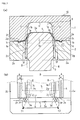
- FIG. 5 For easily describing the following structure, in the direction of the standard axis in Fig. 5 , the arrow X (the product longitudinal direction) shows forward, the arrow Y (the product width direction) shows rightward, the arrow Z (the product heightwise direction) shows upward.
- the mold 30 includes a die 31 as a cope, a blank holder 32, a punch 33 as a drag and so on.
- the die 31 has a recess 31a on the bottom thereof in the downward and longitudinal directions including a bottom 31f, a left face 31 g and a right face 31 h.
- the die 31 has cushion faces 31b and 31c on the bottom thereof, and the recess 31a is formed between the faces.
- the faces 31b and 31c respectively have projected portions 31d and 31e, extending in the longitudinal direction, projecting downward on the faces 31b and 31c.
- the holder 32 is formed with block portions 32a and 32b in the left and right of the holder and has the rectangular shape in plan; the portions 32a and 32b have cushion faces 32c and 32d on the top.
- the faces 32c and 32d have guttered portions 32e and 32f formed on corresponding to the portions 31d and 31e, also extending in the longitudinal direction.
- the faces 32c and 32d of the holder 32 correspond to the faces 31b and 31c of the die 31, the face 31b contacts the face 32c, the face 31c contacts the face 32d.
- the portions 2a and 2b have inside faces 2g and 2h, which form the space where the punch 3 is inserted.
- the distance between faces 2g and 2f is set where the punch 3 can be inserted and a blank 4 (see Fig. 6 ) can be deformed in the cavity 9.
- the punch 33 has a upper face 33a formed on the top corresponding to the bottom face 31e of the die 31, also has side faces 33b and 33c formed on the left and right side corresponding to the faces 31 g and 31 h of the die 31.
- FIG. 6 A conventional open-drawing method using the mold 30 will described, with reference to Fig. 6 .
- a situation and a method of the setting the blank 34 to the mold 30 in the ready state will be described.
- the mold 30 is described in plan with the perspective die 31 as a cope, the die 31 is not described (as the same as in Figs. 2 (b) , 3 (b) , 4 (b) , 7 (b) , and 8 (b) ).
- the mold 30 has a cavity 9 formed by the die 31, the holder 32 and the punch 33.
- the cavity 9 is formed as the desired product shape, the blank 34 is pressed along the cavity 39, the blank 34 becomes the product shape.
- the blank 34 has a parting line 35 set corresponding to the product form and the size thereof.
- the line 35 is a virtual borderline defining the remained area as the product and the cut area.
- the blank 34 has an excess thickness portion 36 set as the outside from the line 35.
- the portion 36 is cut finally and thus it is not the portion forming the product.
- a drawing profile 38 is set as the border between faces 31g, 31h of the die 31 and faces 33b, 33c of the punch 33. The drawing profile comes out as the ridgeline in the corner of the finished product.
- the areas X serve as clamp faces 37 constructed by the portions 31d, 31e and the portions 32e, 32f, and the faces 37 limit the movement and extension of the blank 4.
- the mold 30 can clamp the lateral ends of the blank 34, can not clamp the ends of the blank 34 in the recess side (the longitudinal ends).
- Fig. 7 The situation of the mold 30 and the blank 34 in the way of forming will described, with reference to Fig. 7 .
- the die 31 and the holder 32 are moved down clamping the blank 34, thereby the ready state leads into the press molding state.
- the lateral ends of the blank 34 (the area A in Fig. 7 (b) ) clamped by the die 31 and the holder 32 is moved and stretched vertically to the ridgeline 33d and 33e and is deformed in the cavity 39.
- the blank 34 is clamped by the portions 31d, 31e and the portions 32e, 32f, so that the deformation of the lateral ends of the blank 34 in the cavity 39 is adjusted.
- the recess side of the blank 4 (the area B in Fig. 7 (b) ) not clamped by the die 31 and the holder 32, is not directly clamped by the holder 32 and the punch 33, and is deformed in the cavity 9 in the direction parallel to the ridgeline 33d and 33e. Adjusting the deformation amount of the blank 34 in the cavity 39 is difficult in the way of forming of the conventional press 30.
- Fig. 8 (a) , when the die 31 and the holder 32 come to the bottom dead center, the blank 34 is press molded to the product shape by the recess 31a of the die 31 (faces 31f, 31g, 31h) and the face 33a, 33b, 33c of the punch 33.
- the recess side of the blank 34 (the area B in Fig. 7 (b) ) not clamped by the die 31 and the holder 32 is also clamped by the holder 32 and the punch 33, and is moved and stretched vertically to the ridgeline 33d and 33e, and is deformed in the cavity 39.
- the conventional mold 30 cannot adjust deformation amount of the recess side ends of the blank 34.
- the blank 34 is deformed from the recess sides, so that the wrinkles 40 is generated inside of the parting line 35.
- the parting line 35 may be set inside within the product, so that the portion 36 is extended and the loss of the blank 34 is increased, thereby the yield is decreased.
- the open-drawing mold is not adopted, however, the press mold is adopted having the punch surrounded by the die and the blank holder, and the holding wrinkles face is formed around.
- the deformation amount of the blank is adjusted rightly, but the excess thickness portion 36 clamped by the holding wrinkles face is set larger than the open-drawing mold, thereby the loss of blank 34 is increased and the yield is decreased.
- the open-drawing method has advantage for improving the yield, so the open-drawing method capable of rightly adjusting the blank deformation from the recess side is desired.
- the objective of the present invention is to prevent wrinkles and cracks in the finished product and to improve the yield of the blank, providing the new mold for the press apparatus and the open-drawing method capable of adjusting the deformation amount of the blank from the recess of the mold in the way of forming.
- the first aspect of the present invention is a mold which includes a die having cushion faces and a recess disposed in the longitudinal direction between the cushion faces, a blank holder for clamping a blank with the cushion faces and a punch formed with an upper face corresponding to a bottom of the recess and side faces corresponding to side faces of the recess, using an open-drawing forming.
- a width of the punch is gradually enlarged toward the longitudinal ends thereof in an area correspond to a excess thickness portion of the blank, and ridgelines formed between the upper face and side faces of the punch are curved to the outside of the punch width and to the longitudinal ends thereof.
- the width of the punch is gradually enlarged toward the longitudinal ends thereof and the width of the recess of the die is gradually enlarged toward the longitudinal ends thereof in the area correspond to the excess thickness portion of the blank, and a drawing profile set by the punch and the die is curved to the outside of the punch width and the recess width and to the longitudinal ends thereof.
- the width of the punch is gradually enlarged toward the longitudinal ends thereof in the area correspond to the excess thickness portion of the blank, and the ridgelines formed between the upper face and side faces of the punch are curved to the outside of the punch width and to the longitudinal ends thereof, and the recess width of the die is gradually enlarged toward the longitudinal ends thereof, and the drawing profile set by the punch and the die is curved to the outside of the punch width and the recess width and to the longitudinal ends thereof.
- the second aspect of the present invention is an open-drawing method using the mold comprising the die having cushion faces and the recess disposed in the longitudinal direction between the cushion faces, the blank holder for clamping the blank with the cushion faces and the punch formed with the upper face corresponding to the bottom of the recess and side faces corresponding to side faces of the recess, the die, the blank holder, and the punch forms a cavity as a product shape.
- the punch is provided with a width enlarged portion toward the longitudinal ends thereof and with the curved ridgelines formed between the upper face and side faces of the punch to the outside of the punch width and to the longitudinal ends thereof in the area correspond to the excess thickness portion of the blank, the blank in the cavity is deformed along the ridgelines, and the excess thickness portion is curved to the outside of the punch width and to the longitudinal ends thereof.
- the punch is provided with the width enlarged portion toward the longitudinal ends thereof, with the width enlarged portion of recess of the die toward the longitudinal ends thereof and with the curved drawing profile set the punch and the die to the outside of the punch width and recess width and to the longitudinal ends thereof in the area correspond to the excess thickness portion of the blank, and the blank is curved along the drawing profile by the die, and the excess thickness portion is curved to the outside of the punch and recess widths and to the longitudinal ends thereof.
- the punch is provided with the width enlarged portion toward the longitudinal ends thereof, with the curved ridgelines formed between the upper face and side faces of the punch to the outside of the punch width and to the longitudinal ends thereof in an area correspond to the excess thickness portion of the blank, and the blank is deformed in the cavity along the ridgelines
- the die is provided with the width enlarged portion of recess of the die toward the longitudinal ends thereof and with the curved the drawing profile set the punch and the die to the outside of the punch width and recess width and to the longitudinal ends thereof, and the blank is curved along the drawing profile by the die, and the excess thickness portion is curved to the outside of the punch width and recess width and to the longitudinal ends thereof.
- the present invention shows the following effects.
- the tension exerted to the outside of the recess is certainly added to the blank and the deformation amount of the blank into the cavity from the recess side of the mold is properly adjusted, thereby preventing the wrinkles and cracks in the finished product.
- a mold 10 for a press apparatus will be described with reference to Fig. 1 .
- the arrow X (the product longitudinal direction) shows forward
- the arrow Y (the product width direction) shows rightward
- the arrow Z (the product heightwise direction) shows upward.
- the standard axis is set described easily, does not especially limited to arranged components (a die, a blank holder, a punch, and so on) of the mold.
- the mold 10 includes a die 1 as a cope, a blank holder 2, a punch 3 as a drag and so on.
- the die 1 has a recess 1a on the bottom thereof including a bottom 1f, a left face 1g and a right face 1h, and the die has the recess in the downward and longitudinal directions.
- the die 1 has cushion faces 1b and 1c on the bottom thereof, and the recess 1a is formed between the faces.
- the faces 1b and 1c respectively have projected portions 1d and 1e, extending in the longitudinal direction, projecting downward on the faces 1b and 1c.
- the die 1 has curved portions 1j formed at the longitudinal ends of faces 1g and 1h, curved to the outside in the direction of the axis Y (the product width direction), and in this point it is different from the conventional die 31.
- the holder 2 is formed with block portions 2a and 2b in the left and right of the holder and has the rectangular shape in plan; the portions 2a and 2b have cushion faces 2c and 2d on the top.
- the faces 2c and 2d have guttered portions 2e and 2f formed on corresponding to the portions 1d and 1e, also extending in the longitudinal direction.
- the faces 2c and 2d of the holder 2 correspond to the faces 1b and 1c of the die 1, the face 1b contacts the face 2c, the face 1c contacts the face 2d.
- the portions 2a and 2b have inside faces 2g and 2h, which form the space where the punch 3 is inserted.
- the distance between faces 2g and 2f is set where the punch 3 can be inserted and a blank 4 (see Fig. 2 ) can be deformed.
- the holder 2 has curved portions 2j formed at the longitudinal ends of faces 2g and 2h corresponding to the portions 1j of the die 1, curved to the outside in the direction of the axis Y (the product width direction), and in this point it is different from the conventional holder 32.
- the punch 3 has a upper face 3a formed on the top corresponding to the bottom face 1e of the die 1, also has side faces 3b and 3c formed on the left and right side corresponding to the faces 1g and 1h of the die 1.
- the punch 3 has curved portions 3f formed at the longitudinal ends of faces 3b and 3c corresponding to the portions 1j of the die 1 and portions 2j of the holder 2, curved to the outside in the axis Y (the product width direction).
- the punch 3 has a ridgeline 3d (borderline between faces 3a and 3b), a ridgeline 3e (borderline between faces 3b and 3c), and thus, they and a drawing profile 8 are curved to the outside in the axis Y (the product width direction).
- FIG. 2 A situation and a method of the setting the blank 4 to the mold 10 in the ready state will be described.
- Fig. 2 (a) when the blank 4 is set to the mold 10, the faces 2c and 2d of the holder 2 are kept upper than the face 3a of the punch 3, the blank 4 is set to the faces 2c and 2d of the holder 2.
- the die 1 is moved down and kept the position which the portions 1d and 1e of the die 1 are inserted to the portions 2e and 2f of the holder 2, the blank 4 is clamped by the portions 1d, 1e of the die 1 and the portions 2e, 2f of the holder 2.
- the position keeping the die 1 the height of the portion 1d and 1e and the depth of the portion 2e and 2f are adjusted respectively, thereby adjusting the clamping force for the blank 4 by the die 1 and the holder 2.
- the mold 10 has a cavity 9 as the product shape formed by the die 1, holder 2 and punch 3.
- the blank 4 has a parting line 5 set corresponding to the product form and the size thereof.
- the blank 4 has a excess thickness portion 6 set as the outside from the line 5.
- the drawing profile 8 is set as the border line between faces 1g, 1h of the die 1 and faces 3b, 3c of the punch 3.
- the areas X serve as clamp faces 7 constructed by the portions 1d, 1e and the portions 2e, 2f, and the faces 7 adjust the movement and extension of the blank 4.
- the mold 10 can clamp the lateral ends of the blank 4, can not clamp the ends of the blank 4 in the recess side (the longitudinal ends).
- Fig. 3 (a) the die 1 and holder 2 are moved down clamping the blank 4, the ready state proceeds to the press molding state.
- the lateral ends of the blank 4 (the area A in Fig. 3 (b) ) clamped by the die 1 and holder 2 is moved and stretched vertically to the ridgeline 3d and 3e and is deformed in the cavity 9.
- the blank 4 is clamped by the portions 1d, 1e and the portions 2e, 2f, so that the deformation amount of the lateral ends of the blank 4 in the cavity 9 is adjusted.
- the excess thickness portion 6 of the recess side of the blank 4 (the area B in Fig. 3 (b) ) not clamped by the die 1 and holder 2 is deformed in the cavity 9 curving along the ridgeline 3d and 3e which curve to the outer direction of Y axis (the product width direction).
- the tension is added to the blank 4, exerted to the recess side (in the longitudinal direction, for example the direction showed by the arrow T1 and T2 in Fig. 3 (b) ).
- the tension is generated by deforming the portion 6 into the cavity 9 curving along the ridgelines 3d and 3e, and it should be noted that if the portions 1j are not formed in the die 1, the tension may be exerted.
- the mold 10 includes the die 1 having faces 1b, 1c and an recess 1a disposed in the longitudinal direction between the faces 1b and 1c, the holder 2 for clamping the blank 4 with the faces 1b, 1c and the punch 3 formed with the face 3a corresponding to the bottom 1f of the recess 1a and faces 3b, 3c corresponding to faces 1g, 1h of the recess 1a, in which the width of the punch 3 is gradually enlarged toward the longitudinal ends thereof in the area correspond to the portion 6 of the blank 4, and in which the borderline (the ridgelines 3d, 3e) formed between the face 3a, 3b, 3c of the punch 3 are curved to the outside of the punch width and to the longitudinal ends thereof.
- the borderline the ridgelines 3d, 3e
- the open-drawing method using the mold 10 including the die 1 having faces 1b, 1c and the recess 1a disposed in the longitudinal direction between the faces 1b and 1c, the holder 2 for clamping the blank 4 with the faces 1b, 1c and the punch 3 formed with the face 3a corresponding to the bottom 1f of the recess 1a and faces 3b, 3 c corresponding to faces 1g, 1h of the recess 1a, the die 3, the blank holder 2, and the punch 3 forms the cavity 9 as the product shape, providing the punch 3 with a width enlarged portion toward the longitudinal ends thereof and with curved ridgelines 3d, 3e formed between the face 3a, 3b, 3c of the punch 3 to the outside of the punch width and to the longitudinal ends thereof in the area correspond to the portion 6 of the blank 4, deforming the blank 4 in the cavity 9 along the ridgelines 3d and 3e, curving the portion 6 to the outside of the punch width and to the longitudinal ends thereof.
- the tension exerted to the outside of the recess is certainly added to the blank 4 and the deformation amount of the blank 4 into the cavity 9 from the recess side of the mold 10 is properly adjusted, thereby preventing the wrinkles and cracks in the finished product.
- the portion 6 is curved along the portions 1j (the drawing profile 8), so that the tension is added to the blank 4, exerted to the recess side (in the longitudinal direction, for example the direction showed by the arrow T1 and T2 in Fig. 3 (b) ).
- the portion 6 is curved along the portions 1j (the drawing profile 8), the tension is added, and it should be noted that if the portions 1j are not formed in the die 1, the tension may be exerted.
- the mold 10 includes the die 1 having faces 1b, 1c and the recess 1a disposed in the longitudinal direction between the faces 1b and 1c, the holder 2 for clamping the blank 4 with the faces 1b, 1c and the punch 3 formed with the face 3a corresponding to the bottom 1f of the recess 1a and faces 3b, 3c corresponding to faces 1g, 1h of the recess 1a, in which the width of the punch 3 is gradually enlarged toward the longitudinal ends thereof and the width of the recess 1a of the die 1 is gradually enlarged toward the longitudinal ends thereof in the area correspond to portion 6 of the blank 4, in which the profile 8 set by the punch 3 and the die 1 is curved to the outside of the punch width and the recess widths and to the longitudinal ends thereof.
- the open-drawing method using the mold 10 including the die 1 having faces 1b, 1c and the recess 1a disposed in the longitudinal direction between the faces 1b and 1c, the holder 2 for clamping the blank 4 with the faces 1b, 1c and the punch 3 formed with the face 3a corresponding to the bottom 1f of the recess 1a and faces 3b, 3c corresponding to faces 1g, 1h of the recess 1a, the die 3, the blank holder 2, and the punch 3 forms the cavity 9 as the product shape, providing the punch 3 with a width enlarged portion toward the longitudinal ends thereof and with a curved ridgelines 3d, 3e formed between the face 3a, 3d, 3e of the punch 3 to the outside of the punch width and to the longitudinal ends thereof in the area correspond to the portion 6 of the blank 4, deforming the blank 4 in the cavity 9 along the ridgelines 3d, 3e, curving the 6 to the outside of the punch width and to the longitudinal ends thereof.
- the tension exerted to the outside of the recess is certainly added to the blank 4 and the deformation amount of the blank 4 into the cavity 9 from the recess side of the mold 10 is properly adjusted, thereby preventing the wrinkles and cracks in the finished product.
- the tension can be added to the blank exerting to the recess (in the longitudinal direction).
- the timing is not generated when the blank 4 in the recess side (the area A in Fig. 3 (b) ) is deformed in the cavity 9 not clamped by the die 1 and the holder 3.
- Fig. 4 (a) when the die 1 and holder 2 come to the bottom dead center, the lateral ends of the blank 4 (the area A in Fig. 4 (b) ) clamped by the die 1 and holder 2 is moved and stretched vertically to the ridgeline 3d and 3e and is deformed in the cavity 9.
- the recess sides of the blank 4 (the area B in Fig. 4 (b) ) not clamped by the die 1 and holder 2 is deformed in the cavity 9 curving along the ridgeline 3d and 3e, is curved along to the curved portion 1j (the drawing profile 8), so that the fitting tension is added to the blank 4, exerted to the recess sides (in the longitudinal direction, for example the direction showed by the arrow T3 and T4 in Fig. 4 (b) ), thereby the deformation of the blank is limited.
- the mold 10 includes the die 1 having faces 1b, 1c and the recess 1a disposed in the longitudinal direction between the faces 1b and 1c, the holder 2 for clamping the blank 4 with the faces 1b, 1c and the punch 3 formed with the face 3a corresponding to the bottom 1f of the recess 1a and faces 3b, 3c corresponding to side faces 1g, 1h of the recess 1a, in which the width of the punch 3 is gradually enlarged toward the longitudinal ends thereof in the area correspond to the portion 6 of the blank 4, in which the ridgelines 3d, 3e formed between the face 3a, 3b, 3c of the punch 3 are curved to the outside of the punch width and to the longitudinal ends thereof, in which the recess width of the die 1 is gradually enlarged toward the longitudinal ends thereof, in which the profile 8 set by the punch 3 and the die 1 is curved to the outside of the punch width and the recess width and to the longitudinal ends thereof.
- the open-drawing method using the mold 10 including the die 1 having the faces 1b, 1c and the recess 1a disposed in the longitudinal direction between the faces 1b and 1c, the holder 2 for clamping the blank 4 with the faces 1b, 1c and the punch 3 formed with the face 3a corresponding to the bottom 1f of the recess 1a and the faces 3b, 3c corresponding to the faces 1g, 1h of the recess 1a, the die 1, the holder 2, and the punch 3 forms the cavity 9 as the product shape, providing the punch 3 with the width enlarged portion toward the longitudinal ends thereof and with curved ridgelines 3d, 3e formed between the face 3a, 3b, 3c of the punch 3 to the outside of the punch width and to the longitudinal ends thereof in the area correspond to the portion 6 of the blank 4, deforming the blank 4 in the cavity 9 along the ridgelines 3d, 3e, providing the die 1 with the width enlarged portion of recess toward the longitudinal ends thereof and with the curved portion of the
- the tension is generated synergistically when the portion 6 is curved along the ridgelines 3d, 3e and is curved by the die 1 along the portion 1j thereof, so that the tension exerted to the outside of the recess is certainly added to the blank 4 and the deformation amount of the blank 4 into the cavity 9 from the recess side of the mold 10 is properly adjusted, thereby preventing the wrinkles and cracks in the finished product.
- the portion 6 in the recess side and the ends of the blank 4 are clamped in the way of forming, when the die 1 and holder 2 do not come to the bottom dead center, the deformation amount of the portion 6 in the recess side and the ends of the blank 4 can be limited.
- the portion 6 is not set larger, the blank 4 in the recess side can be limited.
- the wrinkles are not occurred by the deformation of the blank 4 in the recess side unlike the conventional press 30.
- the portion 6 can be set smaller, thereby improving the yield.
- the tension exerted to the longitudinal finished product is higher.
- the deformation of the blank 4 in the cavity 9 is adjusted by changing the curvature of the portion 1j, 3f in plane, so that the deformation of the blank 4 is fine tuned easily by amending the mold.
- the present invention is applicable in the industrial instrument as the mold for the press apparatus and the open-drawing method using the mold, is also applicable to the mold and the method without the recess.
Landscapes
- Engineering & Computer Science (AREA)
- Mechanical Engineering (AREA)
- Shaping Metal By Deep-Drawing, Or The Like (AREA)
Applications Claiming Priority (2)
| Application Number | Priority Date | Filing Date | Title |
|---|---|---|---|
| JP2007310965A JP4386130B2 (ja) | 2007-11-30 | 2007-11-30 | プレス装置用金型および開放絞り成形方法 |
| PCT/JP2008/070464 WO2009069461A1 (ja) | 2007-11-30 | 2008-11-11 | プレス装置用金型および開放絞り成形方法 |
Publications (3)
| Publication Number | Publication Date |
|---|---|
| EP2202011A1 true EP2202011A1 (de) | 2010-06-30 |
| EP2202011A4 EP2202011A4 (de) | 2011-10-05 |
| EP2202011B1 EP2202011B1 (de) | 2012-10-31 |
Family
ID=40678363
Family Applications (1)
| Application Number | Title | Priority Date | Filing Date |
|---|---|---|---|
| EP08855410A Not-in-force EP2202011B1 (de) | 2007-11-30 | 2008-11-11 | Form für eine pressvorrichtung sowie pressenbearbeitungsverfahren und open-drawing-verfahren |
Country Status (5)
| Country | Link |
|---|---|
| US (1) | US8490455B2 (de) |
| EP (1) | EP2202011B1 (de) |
| JP (1) | JP4386130B2 (de) |
| CN (1) | CN101873901B (de) |
| WO (1) | WO2009069461A1 (de) |
Cited By (4)
| Publication number | Priority date | Publication date | Assignee | Title |
|---|---|---|---|---|
| FR3005880A1 (fr) * | 2013-05-22 | 2014-11-28 | Peugeot Citroen Automobiles Sa | Procede d'emboutissage d'une piece, notamment de carrosserie de vehicule automobile, a prise de pince amelioree |
| FR3019765A1 (fr) * | 2014-04-10 | 2015-10-16 | Peugeot Citroen Automobiles Sa | Agencement de serre flan dans un outil d'emboutissage |
| FR3040642A1 (fr) * | 2015-09-03 | 2017-03-10 | Peugeot Citroen Automobiles Sa | Serre-flan d’outil d’emboutissage pour doublure de carrosserie automobile. |
| FR3045424A1 (fr) * | 2015-12-18 | 2017-06-23 | Peugeot Citroen Automobiles Sa | Procede d’emboutissage d’un flan de tole au moyen d’une presse pour obtenir une piece en u et presse pour un tel procede d’emboutissage |
Families Citing this family (14)
| Publication number | Priority date | Publication date | Assignee | Title |
|---|---|---|---|---|
| KR100949463B1 (ko) * | 2009-08-26 | 2010-03-29 | (주)명진 | 샤시의 엠보싱 부위 응력쏠림 방지장치 |
| PH12012501527A1 (en) | 2010-02-04 | 2017-08-09 | Crown Packaging Technology Inc | Can manufacture |
| JP2013523459A (ja) * | 2010-04-12 | 2013-06-17 | クラウン パッケイジング テクノロジー インコーポレイテッド | 缶の製造 |
| US9067251B2 (en) * | 2011-06-13 | 2015-06-30 | GM Global Technology Operations LLC | Method of forming an article from metal alloy sheet material |
| CN103357735B (zh) * | 2012-04-01 | 2015-05-13 | 上海赛科利汽车模具技术应用有限公司 | 车门内板的开口拉延成形工艺 |
| CN102632157A (zh) * | 2012-05-04 | 2012-08-15 | 吉林大学 | 先进高强钢冲压件侧壁卷曲回弹控制方法 |
| US20140020534A1 (en) * | 2012-07-17 | 2014-01-23 | National Taiwan Ocean University | Fine hydro-blanking device |
| JP6119848B2 (ja) * | 2013-05-13 | 2017-04-26 | 新日鐵住金株式会社 | ブランク、成形板、プレス成形品の製造方法及びプレス成形品 |
| US10406587B2 (en) | 2016-03-31 | 2019-09-10 | GM Global Technology Operations LLC | Method and die set for forming a surface in a metal panel |
| CN105921621A (zh) * | 2016-06-06 | 2016-09-07 | 深圳市信维通信股份有限公司 | 一种u型拉伸件拉伸方法及拉伸模具 |
| DE102017120192A1 (de) * | 2017-09-01 | 2019-03-07 | Benteler Automobiltechnik Gmbh | Niederhalterpresse zur Herstellung eines Halbzeugs aus Blechmaterial mit ausgedünnten Bereichen sowie Verfahren zur Herstellung eines Blechumformbauteils |
| JP7153273B2 (ja) * | 2019-06-11 | 2022-10-14 | トヨタ車体株式会社 | 車両用メンバー部品のプレス成形方法及びそのプレス金型 |
| JP7454433B2 (ja) * | 2020-04-09 | 2024-03-22 | 東プレ株式会社 | ハット形状成形部品の製造方法、および金型 |
| JP7589120B2 (ja) * | 2021-08-20 | 2024-11-25 | 本田技研工業株式会社 | 成形装置及び該成形装置を用いた成形方法 |
Family Cites Families (14)
| Publication number | Priority date | Publication date | Assignee | Title |
|---|---|---|---|---|
| US3263637A (en) * | 1964-12-23 | 1966-08-02 | Darwin S Cox | Method of deep drawing rectangular shapes |
| JPS582501Y2 (ja) * | 1979-01-19 | 1983-01-17 | 東京プレス工業株式会社 | プレス成形型 |
| FR2564339B1 (fr) * | 1984-05-17 | 1987-12-24 | Usinor | Procede et dispositif d'emboutissage de toles. |
| US4615205A (en) * | 1984-06-18 | 1986-10-07 | Rca Corporation | Forming a shadow mask from a flat blank |
| US4719787A (en) * | 1986-08-29 | 1988-01-19 | Rca Corporation | Apparatus for forming a shadow mask |
| JP2547772B2 (ja) * | 1987-06-13 | 1996-10-23 | 日産自動車株式会社 | 絞り成形方法 |
| JP2506400B2 (ja) | 1988-02-01 | 1996-06-12 | 日産自動車株式会社 | 絞り成形方法 |
| JPH0255624A (ja) | 1988-08-22 | 1990-02-26 | Toyota Motor Corp | 一側部が開放された凹部を有する製品の成形方法 |
| JPH0446637A (ja) | 1990-06-14 | 1992-02-17 | Nissan Motor Co Ltd | プレス型 |
| JPH0825097A (ja) | 1994-07-19 | 1996-01-30 | Kawasaki Steel Corp | プレス加工用金型 |
| JP2000102824A (ja) | 1998-09-29 | 2000-04-11 | Matsushita Electric Ind Co Ltd | 成形金型 |
| JP3864038B2 (ja) * | 1999-07-30 | 2006-12-27 | 伊田 忠一 | 深絞り成形加工法 |
| DE112005002868B4 (de) * | 2004-11-24 | 2010-07-01 | Honda Motor Co., Ltd. | Ziehformungsverfahren und -vorrichtung |
| JP4787548B2 (ja) * | 2005-06-07 | 2011-10-05 | 株式会社アミノ | 薄板の成形方法および装置 |
-
2007
- 2007-11-30 JP JP2007310965A patent/JP4386130B2/ja not_active Expired - Fee Related
-
2008
- 2008-11-11 US US12/678,593 patent/US8490455B2/en not_active Expired - Fee Related
- 2008-11-11 EP EP08855410A patent/EP2202011B1/de not_active Not-in-force
- 2008-11-11 CN CN2008801176865A patent/CN101873901B/zh not_active Expired - Fee Related
- 2008-11-11 WO PCT/JP2008/070464 patent/WO2009069461A1/ja not_active Ceased
Cited By (6)
| Publication number | Priority date | Publication date | Assignee | Title |
|---|---|---|---|---|
| FR3005880A1 (fr) * | 2013-05-22 | 2014-11-28 | Peugeot Citroen Automobiles Sa | Procede d'emboutissage d'une piece, notamment de carrosserie de vehicule automobile, a prise de pince amelioree |
| FR3019765A1 (fr) * | 2014-04-10 | 2015-10-16 | Peugeot Citroen Automobiles Sa | Agencement de serre flan dans un outil d'emboutissage |
| FR3040642A1 (fr) * | 2015-09-03 | 2017-03-10 | Peugeot Citroen Automobiles Sa | Serre-flan d’outil d’emboutissage pour doublure de carrosserie automobile. |
| CN106493208A (zh) * | 2015-09-03 | 2017-03-15 | 标致雪铁龙集团 | 用于机动车辆车身衬里的冲压工具的压边圈 |
| CN106493208B (zh) * | 2015-09-03 | 2019-12-20 | 标致雪铁龙集团 | 用于机动车辆车身衬里的冲压工具的压边圈 |
| FR3045424A1 (fr) * | 2015-12-18 | 2017-06-23 | Peugeot Citroen Automobiles Sa | Procede d’emboutissage d’un flan de tole au moyen d’une presse pour obtenir une piece en u et presse pour un tel procede d’emboutissage |
Also Published As
| Publication number | Publication date |
|---|---|
| US8490455B2 (en) | 2013-07-23 |
| CN101873901A (zh) | 2010-10-27 |
| WO2009069461A1 (ja) | 2009-06-04 |
| CN101873901B (zh) | 2013-01-16 |
| EP2202011A4 (de) | 2011-10-05 |
| US20100201031A1 (en) | 2010-08-12 |
| JP4386130B2 (ja) | 2009-12-16 |
| EP2202011B1 (de) | 2012-10-31 |
| JP2009131878A (ja) | 2009-06-18 |
Similar Documents
| Publication | Publication Date | Title |
|---|---|---|
| EP2202011A1 (de) | Form für eine pressvorrichtung sowie pressenbearbeitungsverfahren und open-drawing-verfahren | |
| JP2009160591A (ja) | プレス成形方法およびプレス成形装置 | |
| JP2012254483A (ja) | プレス成形品、プレス成形品の製造方法および製造装置 | |
| JP2009094102A (ja) | リード成型装置およびリード成型方法 | |
| JP2021167002A (ja) | ハット形状成形部品の製造方法、および金型 | |
| JP3546718B2 (ja) | プレス成形方法 | |
| CN205763290U (zh) | 一种细长五金件的冲压模具 | |
| GB2253364A (en) | A method for roll forming of semiconductor component leads | |
| JP2003078095A (ja) | リード加工装置 | |
| KR100858728B1 (ko) | 프로그레시브 금형의 스크랩 절단장치 | |
| KR20230001606A (ko) | 무브릿지 프로그래시브 금형 및 공법 | |
| CN104972006B (zh) | 冲压模具 | |
| JP2015077621A (ja) | プレス加工方法 | |
| KR101965392B1 (ko) | 가변 그루브 핀이 적용된 펀치를 갖는 코이닝 장치 | |
| JP6686853B2 (ja) | プレス成形装置 | |
| JP2001168258A (ja) | 電子部品の製造方法及びその装置 | |
| JP2010105020A (ja) | プレス曲げ機用金型 | |
| JP2007152417A (ja) | 曲げ金型装置及び曲げ加工方法 | |
| CN210146773U (zh) | 一种支撑台冲压模具 | |
| KR200464012Y1 (ko) | 다양한 크기의 판넬 컷팅이 가능한 프레스 금형 | |
| JP2001252728A (ja) | プレス装置の押しズレ防止構造 | |
| JP2002248526A (ja) | 順送り型 | |
| KR100733349B1 (ko) | 핀조절식 펀칭금형 | |
| CN220144491U (zh) | 矩形薄片成型料带及半剪切模具 | |
| CN214488655U (zh) | 一种连接器端子冲压模具 |
Legal Events
| Date | Code | Title | Description |
|---|---|---|---|
| PUAI | Public reference made under article 153(3) epc to a published international application that has entered the european phase |
Free format text: ORIGINAL CODE: 0009012 |
|
| 17P | Request for examination filed |
Effective date: 20100329 |
|
| AK | Designated contracting states |
Kind code of ref document: A1 Designated state(s): AT BE BG CH CY CZ DE DK EE ES FI FR GB GR HR HU IE IS IT LI LT LU LV MC MT NL NO PL PT RO SE SI SK TR |
|
| AX | Request for extension of the european patent |
Extension state: AL BA MK RS |
|
| DAX | Request for extension of the european patent (deleted) | ||
| A4 | Supplementary search report drawn up and despatched |
Effective date: 20110905 |
|
| RIC1 | Information provided on ipc code assigned before grant |
Ipc: B21D 22/06 20060101ALI20110830BHEP Ipc: B21D 24/00 20060101AFI20110830BHEP Ipc: B21D 24/04 20060101ALI20110830BHEP Ipc: B21D 22/22 20060101ALI20110830BHEP Ipc: B21D 22/02 20060101ALI20110830BHEP |
|
| RIC1 | Information provided on ipc code assigned before grant |
Ipc: B21D 24/00 20060101AFI20120312BHEP Ipc: B21D 22/22 20060101ALI20120312BHEP Ipc: B21D 24/04 20060101ALI20120312BHEP Ipc: B21D 22/06 20060101ALI20120312BHEP Ipc: B21D 22/02 20060101ALI20120312BHEP |
|
| GRAP | Despatch of communication of intention to grant a patent |
Free format text: ORIGINAL CODE: EPIDOSNIGR1 |
|
| GRAS | Grant fee paid |
Free format text: ORIGINAL CODE: EPIDOSNIGR3 |
|
| GRAA | (expected) grant |
Free format text: ORIGINAL CODE: 0009210 |
|
| AK | Designated contracting states |
Kind code of ref document: B1 Designated state(s): AT BE BG CH CY CZ DE DK EE ES FI FR GB GR HR HU IE IS IT LI LT LU LV MC MT NL NO PL PT RO SE SI SK TR |
|
| REG | Reference to a national code |
Ref country code: GB Ref legal event code: FG4D Ref country code: CH Ref legal event code: EP |
|
| REG | Reference to a national code |
Ref country code: AT Ref legal event code: REF Ref document number: 581696 Country of ref document: AT Kind code of ref document: T Effective date: 20121115 |
|
| REG | Reference to a national code |
Ref country code: IE Ref legal event code: FG4D |
|
| REG | Reference to a national code |
Ref country code: DE Ref legal event code: R096 Ref document number: 602008019864 Country of ref document: DE Effective date: 20121227 |
|
| RAP2 | Party data changed (patent owner data changed or rights of a patent transferred) |
Owner name: TOYOTA JIDOSHA KABUSHIKI KAISHA |
|
| REG | Reference to a national code |
Ref country code: AT Ref legal event code: MK05 Ref document number: 581696 Country of ref document: AT Kind code of ref document: T Effective date: 20121031 |
|
| REG | Reference to a national code |
Ref country code: LT Ref legal event code: MG4D |
|
| REG | Reference to a national code |
Ref country code: NL Ref legal event code: VDEP Effective date: 20121031 |
|
| PG25 | Lapsed in a contracting state [announced via postgrant information from national office to epo] |
Ref country code: LT Free format text: LAPSE BECAUSE OF FAILURE TO SUBMIT A TRANSLATION OF THE DESCRIPTION OR TO PAY THE FEE WITHIN THE PRESCRIBED TIME-LIMIT Effective date: 20121031 Ref country code: IS Free format text: LAPSE BECAUSE OF FAILURE TO SUBMIT A TRANSLATION OF THE DESCRIPTION OR TO PAY THE FEE WITHIN THE PRESCRIBED TIME-LIMIT Effective date: 20130228 Ref country code: NL Free format text: LAPSE BECAUSE OF FAILURE TO SUBMIT A TRANSLATION OF THE DESCRIPTION OR TO PAY THE FEE WITHIN THE PRESCRIBED TIME-LIMIT Effective date: 20121031 Ref country code: SE Free format text: LAPSE BECAUSE OF FAILURE TO SUBMIT A TRANSLATION OF THE DESCRIPTION OR TO PAY THE FEE WITHIN THE PRESCRIBED TIME-LIMIT Effective date: 20121031 Ref country code: HR Free format text: LAPSE BECAUSE OF FAILURE TO SUBMIT A TRANSLATION OF THE DESCRIPTION OR TO PAY THE FEE WITHIN THE PRESCRIBED TIME-LIMIT Effective date: 20121031 Ref country code: FI Free format text: LAPSE BECAUSE OF FAILURE TO SUBMIT A TRANSLATION OF THE DESCRIPTION OR TO PAY THE FEE WITHIN THE PRESCRIBED TIME-LIMIT Effective date: 20121031 Ref country code: ES Free format text: LAPSE BECAUSE OF FAILURE TO SUBMIT A TRANSLATION OF THE DESCRIPTION OR TO PAY THE FEE WITHIN THE PRESCRIBED TIME-LIMIT Effective date: 20130211 Ref country code: NO Free format text: LAPSE BECAUSE OF FAILURE TO SUBMIT A TRANSLATION OF THE DESCRIPTION OR TO PAY THE FEE WITHIN THE PRESCRIBED TIME-LIMIT Effective date: 20130131 |
|
| PG25 | Lapsed in a contracting state [announced via postgrant information from national office to epo] |
Ref country code: PT Free format text: LAPSE BECAUSE OF FAILURE TO SUBMIT A TRANSLATION OF THE DESCRIPTION OR TO PAY THE FEE WITHIN THE PRESCRIBED TIME-LIMIT Effective date: 20130228 Ref country code: SI Free format text: LAPSE BECAUSE OF FAILURE TO SUBMIT A TRANSLATION OF THE DESCRIPTION OR TO PAY THE FEE WITHIN THE PRESCRIBED TIME-LIMIT Effective date: 20121031 Ref country code: LV Free format text: LAPSE BECAUSE OF FAILURE TO SUBMIT A TRANSLATION OF THE DESCRIPTION OR TO PAY THE FEE WITHIN THE PRESCRIBED TIME-LIMIT Effective date: 20121031 Ref country code: PL Free format text: LAPSE BECAUSE OF FAILURE TO SUBMIT A TRANSLATION OF THE DESCRIPTION OR TO PAY THE FEE WITHIN THE PRESCRIBED TIME-LIMIT Effective date: 20121031 Ref country code: BE Free format text: LAPSE BECAUSE OF FAILURE TO SUBMIT A TRANSLATION OF THE DESCRIPTION OR TO PAY THE FEE WITHIN THE PRESCRIBED TIME-LIMIT Effective date: 20121031 Ref country code: GR Free format text: LAPSE BECAUSE OF FAILURE TO SUBMIT A TRANSLATION OF THE DESCRIPTION OR TO PAY THE FEE WITHIN THE PRESCRIBED TIME-LIMIT Effective date: 20130201 |
|
| PG25 | Lapsed in a contracting state [announced via postgrant information from national office to epo] |
Ref country code: AT Free format text: LAPSE BECAUSE OF FAILURE TO SUBMIT A TRANSLATION OF THE DESCRIPTION OR TO PAY THE FEE WITHIN THE PRESCRIBED TIME-LIMIT Effective date: 20121031 |
|
| REG | Reference to a national code |
Ref country code: CH Ref legal event code: PL |
|
| PG25 | Lapsed in a contracting state [announced via postgrant information from national office to epo] |
Ref country code: EE Free format text: LAPSE BECAUSE OF FAILURE TO SUBMIT A TRANSLATION OF THE DESCRIPTION OR TO PAY THE FEE WITHIN THE PRESCRIBED TIME-LIMIT Effective date: 20121031 Ref country code: CZ Free format text: LAPSE BECAUSE OF FAILURE TO SUBMIT A TRANSLATION OF THE DESCRIPTION OR TO PAY THE FEE WITHIN THE PRESCRIBED TIME-LIMIT Effective date: 20121031 Ref country code: DK Free format text: LAPSE BECAUSE OF FAILURE TO SUBMIT A TRANSLATION OF THE DESCRIPTION OR TO PAY THE FEE WITHIN THE PRESCRIBED TIME-LIMIT Effective date: 20121031 Ref country code: CH Free format text: LAPSE BECAUSE OF NON-PAYMENT OF DUE FEES Effective date: 20121130 Ref country code: LI Free format text: LAPSE BECAUSE OF NON-PAYMENT OF DUE FEES Effective date: 20121130 Ref country code: SK Free format text: LAPSE BECAUSE OF FAILURE TO SUBMIT A TRANSLATION OF THE DESCRIPTION OR TO PAY THE FEE WITHIN THE PRESCRIBED TIME-LIMIT Effective date: 20121031 Ref country code: BG Free format text: LAPSE BECAUSE OF FAILURE TO SUBMIT A TRANSLATION OF THE DESCRIPTION OR TO PAY THE FEE WITHIN THE PRESCRIBED TIME-LIMIT Effective date: 20130131 |
|
| REG | Reference to a national code |
Ref country code: IE Ref legal event code: MM4A |
|
| PG25 | Lapsed in a contracting state [announced via postgrant information from national office to epo] |
Ref country code: RO Free format text: LAPSE BECAUSE OF FAILURE TO SUBMIT A TRANSLATION OF THE DESCRIPTION OR TO PAY THE FEE WITHIN THE PRESCRIBED TIME-LIMIT Effective date: 20121031 Ref country code: IT Free format text: LAPSE BECAUSE OF FAILURE TO SUBMIT A TRANSLATION OF THE DESCRIPTION OR TO PAY THE FEE WITHIN THE PRESCRIBED TIME-LIMIT Effective date: 20121031 |
|
| PLBE | No opposition filed within time limit |
Free format text: ORIGINAL CODE: 0009261 |
|
| STAA | Information on the status of an ep patent application or granted ep patent |
Free format text: STATUS: NO OPPOSITION FILED WITHIN TIME LIMIT |
|
| 26N | No opposition filed |
Effective date: 20130801 |
|
| PG25 | Lapsed in a contracting state [announced via postgrant information from national office to epo] |
Ref country code: IE Free format text: LAPSE BECAUSE OF NON-PAYMENT OF DUE FEES Effective date: 20121111 |
|
| REG | Reference to a national code |
Ref country code: DE Ref legal event code: R097 Ref document number: 602008019864 Country of ref document: DE Effective date: 20130801 |
|
| PG25 | Lapsed in a contracting state [announced via postgrant information from national office to epo] |
Ref country code: CY Free format text: LAPSE BECAUSE OF FAILURE TO SUBMIT A TRANSLATION OF THE DESCRIPTION OR TO PAY THE FEE WITHIN THE PRESCRIBED TIME-LIMIT Effective date: 20121031 Ref country code: MT Free format text: LAPSE BECAUSE OF FAILURE TO SUBMIT A TRANSLATION OF THE DESCRIPTION OR TO PAY THE FEE WITHIN THE PRESCRIBED TIME-LIMIT Effective date: 20121031 |
|
| PG25 | Lapsed in a contracting state [announced via postgrant information from national office to epo] |
Ref country code: TR Free format text: LAPSE BECAUSE OF FAILURE TO SUBMIT A TRANSLATION OF THE DESCRIPTION OR TO PAY THE FEE WITHIN THE PRESCRIBED TIME-LIMIT Effective date: 20121031 Ref country code: MC Free format text: LAPSE BECAUSE OF NON-PAYMENT OF DUE FEES Effective date: 20121130 |
|
| PG25 | Lapsed in a contracting state [announced via postgrant information from national office to epo] |
Ref country code: LU Free format text: LAPSE BECAUSE OF NON-PAYMENT OF DUE FEES Effective date: 20121111 |
|
| PG25 | Lapsed in a contracting state [announced via postgrant information from national office to epo] |
Ref country code: HU Free format text: LAPSE BECAUSE OF FAILURE TO SUBMIT A TRANSLATION OF THE DESCRIPTION OR TO PAY THE FEE WITHIN THE PRESCRIBED TIME-LIMIT Effective date: 20081111 |
|
| REG | Reference to a national code |
Ref country code: DE Ref legal event code: R084 Ref document number: 602008019864 Country of ref document: DE |
|
| REG | Reference to a national code |
Ref country code: GB Ref legal event code: 746 Effective date: 20140917 |
|
| REG | Reference to a national code |
Ref country code: DE Ref legal event code: R084 Ref document number: 602008019864 Country of ref document: DE Effective date: 20140910 |
|
| REG | Reference to a national code |
Ref country code: FR Ref legal event code: PLFP Year of fee payment: 8 |
|
| REG | Reference to a national code |
Ref country code: FR Ref legal event code: PLFP Year of fee payment: 9 |
|
| REG | Reference to a national code |
Ref country code: FR Ref legal event code: PLFP Year of fee payment: 10 |
|
| REG | Reference to a national code |
Ref country code: FR Ref legal event code: PLFP Year of fee payment: 11 |
|
| PGFP | Annual fee paid to national office [announced via postgrant information from national office to epo] |
Ref country code: GB Payment date: 20201104 Year of fee payment: 13 Ref country code: DE Payment date: 20201028 Year of fee payment: 13 Ref country code: FR Payment date: 20201013 Year of fee payment: 13 |
|
| REG | Reference to a national code |
Ref country code: DE Ref legal event code: R119 Ref document number: 602008019864 Country of ref document: DE |
|
| GBPC | Gb: european patent ceased through non-payment of renewal fee |
Effective date: 20211111 |
|
| PG25 | Lapsed in a contracting state [announced via postgrant information from national office to epo] |
Ref country code: GB Free format text: LAPSE BECAUSE OF NON-PAYMENT OF DUE FEES Effective date: 20211111 Ref country code: DE Free format text: LAPSE BECAUSE OF NON-PAYMENT OF DUE FEES Effective date: 20220601 |
|
| PG25 | Lapsed in a contracting state [announced via postgrant information from national office to epo] |
Ref country code: FR Free format text: LAPSE BECAUSE OF NON-PAYMENT OF DUE FEES Effective date: 20211130 |