EP2200478B2 - Kantenleiste für möbelstücke - Google Patents
Kantenleiste für möbelstücke Download PDFInfo
- Publication number
- EP2200478B2 EP2200478B2 EP08841486.7A EP08841486A EP2200478B2 EP 2200478 B2 EP2200478 B2 EP 2200478B2 EP 08841486 A EP08841486 A EP 08841486A EP 2200478 B2 EP2200478 B2 EP 2200478B2
- Authority
- EP
- European Patent Office
- Prior art keywords
- edge
- furniture
- piece
- base body
- edge strip
- Prior art date
- Legal status (The legal status is an assumption and is not a legal conclusion. Google has not performed a legal analysis and makes no representation as to the accuracy of the status listed.)
- Active
Links
Images
Classifications
-
- A—HUMAN NECESSITIES
- A47—FURNITURE; DOMESTIC ARTICLES OR APPLIANCES; COFFEE MILLS; SPICE MILLS; SUCTION CLEANERS IN GENERAL
- A47B—TABLES; DESKS; OFFICE FURNITURE; CABINETS; DRAWERS; GENERAL DETAILS OF FURNITURE
- A47B95/00—Fittings for furniture
- A47B95/04—Keyplates; Ornaments or the like
- A47B95/043—Protecting rims, buffers or the like
Definitions
- the invention relates to a piece of furniture with an edge strip.
- Such edge strips are, for example, from the DE 34 02 923 A1 , EP 1 080 854 B1 or DE 199 40 329 A1 known.
- the EP 1 479 524 B1 discloses a chipboard with a plastic edge band.
- the publication EP 0125336 A1 further discloses a profile or edge strip for covering furniture panels or the like.
- a rigid strip body of this profile or edge strip has an outer zone which forms the visible side and is partially flexible and which is covered with a decorative film.
- the strip body comprises two recesses running in the longitudinal direction of the strip, which extend from the inside of the strip into the strip body so far that the width of the profile strip can be reduced by pressing the recesses together.
- the recesses are slot-shaped and have a wedge-shaped cross-section and taper towards the outer zone.
- the DE 87 00 536 U1 reveals an edge strip for the furniture industry.
- edge strips are produced in such a way that they are approximately 2 to 4 mm wider than the thickness of a furniture board.
- the furniture board is 25 mm thick, while the edge strip is approximately 28 mm wide.
- the protruding edge of the edge strip is milled flush using various, well-known processing machines. This means that approximately 10 to 20% of the edge strip is removed during post-processing.
- Another disadvantage is that the processing machine has a long machine length and high investment costs due to the extensive post-processing.
- the invention is based on the object of eliminating the disadvantages of the prior art and providing a correspondingly improved piece of furniture.
- the invention provides the piece of furniture according to the features of claim 1.
- the edge strip is already made to the thickness of the piece of furniture and is decorated in the transition area, which creates a smooth transition between the top of the edge strip and the top of the piece of furniture.
- no material-removing post-processing of the narrow sides of the edge strip is required, so that the decoration is not removed in the transition section and the aims and objectives of the invention defined at the beginning are achieved or solved.
- a preferred embodiment of the invention relates to a piece of furniture according to the preceding embodiment, wherein the transition section has a curvature, preferably a curvature with a constant radius of curvature.
- This measure has the advantage that such a curvature is easy to produce due to the geometric regularity and that the decoration can be applied conveniently and economically.
- a further preferred embodiment of the invention relates to a piece of furniture according to one of the preceding embodiments, wherein the transition section has a surface that is inclined relative to the underside.
- This measure has the advantage that such an edge strip achieves a particularly high-quality visual impression, e.g. due to light reflections on the inclined surface, and the surface is easy to decorate using conventional methods.
- the transition region directly borders on an edge of the base body, i.e. an edge of the upper side of the base body and/or an edge of the lower side of the base body.
- This measure has the advantage that a smooth transition to a surface of a piece of furniture adjacent to the edge strip can be achieved.
- the decoration covers the entire surface of the transition section. This measure has the advantage that the transition section can be provided with a decoration that extends to the edge of the edge strip, thus creating a correspondingly high-quality appearance.
- the decor covers the entire top of the edge strip. This measure has the advantage that the surface of the base body can be sealed at the same time by the decor.
- the invention relates to a piece of furniture, the decoration of which is printed on.
- This measure has the advantage that the printing technology, in particular an inkjet printing technology, but also the so-called digital printing for round surfaces, is particularly suitable for mass production.
- the base body is made of plastic. This measure has the advantage that such materials can be easily shaped and are particularly suitable for use as edge strips on high-quality pieces of furniture.
- the base body is an extruded profile made of plastic. This measure has the advantage that such an extruded profile can be produced particularly economically as a strand-like extrudate in a continuous process.
- the intended cross-sectional shape of the edge strip is produced particularly advantageously using the extrusion process or the co-extrusion process with high dimensional accuracy.
- the base body comprises polyamide (PA), polypropylene (PP), polyvinyl chloride (PVC), acrylonitrile-butadiene-styrene copolymer (ABS), polycarbonate (PC), styrene-butadiene (SB), polyethylene terephthalate (PET) and/or polymethyl methacrylate (PMMA).
- PA polyamide
- PP polypropylene
- PVC polyvinyl chloride
- ABS acrylonitrile-butadiene-styrene copolymer
- PC polycarbonate
- SB polyethylene terephthalate
- PET polymethyl methacrylate
- PMMA polymethyl methacrylate
- a further preferred embodiment of the invention relates to a piece of furniture according to one of the preceding embodiments, wherein the edge strip has a width of 10 mm to 150 mm, preferably 15 mm to 50 mm, preferably 20 mm to 30 mm.
- This measure has the advantage that the most common applications for pieces of furniture are covered by the edge strips with such widths.
- the invention relates to a piece of furniture with an edge strip according to one of the preceding embodiments, wherein the edge strip is applied to an edge of the piece of furniture.
- This measure has the advantage that the edge strip visually covers and protects the edge of the furniture, in particular when it is a cut edge of the piece of furniture, for example preventing moisture from entering the piece of furniture via the covered edge.
- the top of the piece of furniture is usually more visible to an observer than, for example, the bottom of the piece of furniture.
- the invention relates to a piece of furniture according to one of the preceding embodiments, wherein an edge of the edge strip lies flush with at least one edge of the edge of the piece of furniture.
- This measure has the advantage that the edge strip creates a smooth transition between the edge strip and the piece of furniture without reworking an upper visible edge, so that the visual appearance or the decoration of the edge strip is not impaired.
- the invention relates to a piece of furniture with an edge strip.
- the edge strip comprises a base body 1 with a bottom 2 that can be placed on a piece of furniture 6 and an upper side 3, 4 facing away from the bottom 2, wherein the upper side 3, 4 has at least one transition section 3 that slopes down towards an edge UR, OR of the base body 1, wherein the transition section 3 has a decoration 5 at least in sections.
- transition section is to be understood in the context of this description as referring to the surface section of a section of the base body 1 in which a thickness of the base body 1 changes in the direction of a width.
- the term "sloping down towards an edge” in this context means that the thickness of the base body 1 decreases towards a lateral edge UR, OR.
- the transition section 3 can have a curvature or form an inclined plane to the bottom 2 or to a contact plane defined by the bottom 2.
- the distance between the lateral edges of the base body 1 i.e. the distance between the upper edges OR and the distance between the lower edges UR
- the distance between the lateral edges of the base body 1 is referred to as the width of the base body 1 or the width of the edge strip.
- An extension of the base body 1 perpendicular to a contact plane defined by the underside 2 is referred to as the thickness of the base body 1 or the thickness of the edge strip.
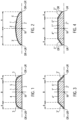
- FIGS. 1 to 4 show preferred cross-sectional shapes of the edge strip in a cross-section perpendicular to the respective longitudinal direction L of the edge strip.
- the base body 1 of the edge strip is made of plastic.
- the base body 1 of the edge strip is an extrusion profile made of a plastic (mixture) of the materials polypropylene (PP), polyamide (PA), polyvinyl chloride (PVC), polymethyl methacrylate (PMMA), acrylonitrile-butadiene-styrene copolymer (ABS), polycarbonate (PC)), polyethylene terephthalate (PET) and/or styrene butadiene (SB).
- the edge strip is extruded in an extrusion device with a width between 10 mm and 150 mm, preferably 15 mm to 50 mm, preferably 20 to 30 mm, calibrated and cooled.
- the underside 2 of the base body 1 defines a contact plane and is preferably flat in order to be brought into contact with an edge 7 of a piece of furniture 6.
- the underside 2 is laterally delimited by the lower edges UR.
- the upper side 3, 4 is laterally delimited by the upper edges OR.
- the decoration 5 is preferably a color print applied using an inkjet process. Any color print pattern can be displayed.
- the color printing device preferably works with digital technology, i.e. image files can be provided from a computer device for printing on the base body 1.
- suitable measures are preferably taken, such as a corona treatment and/or the application of an adhesion promoter to the base body 1 before applying the decoration 5.
- the decoration 5 can be subsequently coated with a clear varnish. Multi-layer decorations or varnishes to create a spatial effect are also understood as decoration 5 in the sense of this invention.
- a first embodiment of the edge strip is described below with reference to Figure 1 described.
- the base body 1 of the edge strip comprises the underside 2 that can be placed on the piece of furniture 6, the upper side 3, 4 facing away from the underside 2, wherein the upper side 3, 4 has two transition sections 3 and a flat section 4.
- the underside 2 of the base body 1 is flat.
- an upper edge OR coincides with a lower edge UR.
- the transition sections 3 each have a curvature with a constant radius of curvature and each run from an edge OR of the base body 1 over a width A to the flat section 4, which extends parallel to the underside 2.
- the flat section 4 spans a width B and extends between the two transition sections 3.
- the transition sections 3 thus slope down from the flat section 4 towards an edge OR.
- the thickness of the edge strip in the area of the flat section 4 is between 1 mm and 5 mm, preferably between 2 mm and 3 mm.
- the radius of curvature of the curvature of the transition section 3 preferably corresponds to the thickness of the base body 1 in the area of the flat section 4, i.e. the distance of the flat section 4 from the underside 2 of the base body 1.
- the ratio A/B is preferably approximately 0.2 to 1.0.
- the decoration 5 covers and conceals the entire upper side 3, 4 of the edge strip, i.e. both the flat section 4 and the two transition sections 3.
- the edge strip has a mirror-symmetrical structure.
- a second embodiment of the edge strip is described below with reference to Figure 2 described.
- the base body 1' of the edge strip has a substantially lens-shaped form.
- the underside 2' is flat and the top side 3' of the base body 1' opposite the underside 2' is continuously curved between the left upper edge OR and the right upper edge OR.
- the radius of curvature of the curved top side 3' corresponds approximately to the width of the edge strip.
- a decoration 5' is applied over the entire top side 3'.
- the transition sections 3' slope down from the middle of the edge strip 1 (half the distance between the upper edges OR) to the upper edges OR.
- an upper edge OR coincides with a lower edge UR.
- the edge strip has a substantially trapezoidal cross-sectional shape.
- the base body 1" comprises the underside 2" to be brought into contact with the piece of furniture 6, the transition sections 3" immediately adjacent to the lower edges UR or upper edges OR, each with an inclined surface inclined at an acute angle of approximately 45° to the underside 2", and the flat section 4" located between the two transition sections 3", which extends parallel to the underside 2" of the edge strip.
- Each transition section 3" extends from the upper edge OR or lower edge UR over a width A.
- the flat section 4" extends between the two transition sections 3" over a width B.
- the ratio A/B is preferably approximately 0.2 to 1.0.
- the edge strip has a substantially trapezoidal cross-sectional shape as in Figure 3 , whereby, however, the upper edges OR are spaced from the lower edges UR, so that a narrow side is formed between an upper edge OR and a lower edge UR of the edge strip.
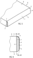
- Fig. 5 shows a piece of furniture 6 according to the invention with an edge strip that is applied to an edge 7 of the piece of furniture 6.
- the piece of furniture 6 is a chipboard/MDF/wooden board.
- the edge strip is preferably produced with an oversize of less than 0.7 mm, preferably less than 0.5 mm, preferably less than 0.3 mm over the board width and is moved to the edge 7 of the piece of furniture 6 in such a way that it ends flush with an edge edge, ie flush with the top 8 of the furniture board 6.
- the mounted edge strip is flush with the upper edge OR, i.e. flush with the top 8 of the piece of furniture 6, and completely covers the edge 7. This creates a smooth transition at the upper edge between the top 8 of the piece of furniture 6 and the top 3, 4 of the edge strip.
- the outline of the assembled edge strip before subsequent machining for adaptation to the specific application is shown with the dashed line.
- the outline of the assembled and reworked edge strip is shown with the solid line.
- the lower, longitudinal visible edge of the edge strip is subsequently profiled and, for example, rounded, so that the edge strip also ends flush with the lower edge, i.e. flush with the underside 9 of the piece of furniture 6.
- the decor 5 is removed in the transition section 3 on the lower visible edge of the edge strip.
- the underside of the respective table top or kitchen worktop is difficult to see, particularly when the edge strip is used to cover table edges or edges of kitchen worktops.
- edge strips must be cut in accordance with the Figures 2 to 4 in the same way as the edge strip according to Figure 1 be mounted, although in Figure 6 only the application and installation of the edge strip according to Figure 1 shown.
- a base body 1 is prepared according to the Figures 1 to 4 e.g. produced as an extrusion profile made of plastic.
- a plastic material is melted and extruded.
- the shaping takes place in an extrusion tool and downstream, preferably water-filled calibration devices in order to give the base body 1 its intended cross-sectional shape with high dimensional accuracy.
- a downstream decoration application device with e.g. digital color printing device, the top side 3, 4 of the Edge strip is first pre-treated to improve adhesion and receptivity for decor 5.
- the upper side 3, 4 of the base body 1 is subjected to a corona treatment or plasma treatment and/or treated with an adhesion promoter.
- a decoration 5 is then applied over the entire upper side 3, 4 of the base body 1, so that the decoration 5 completely covers and conceals the upper side 3, 4 of the base body 1.
- the decoration 5 extends directly to both upper edges OR of the edge strip.
- the base body 1 is sealed in the process.
- a clear varnish can be applied after the decoration 5 has been printed and can be hardened, for example, by ultraviolet radiation.
- the edge strip is then attached with the underside 2 to the edge 7 of the piece of furniture 6, for example by gluing or welding, and is arranged in such a way that an edge OR, UR of the base body 1 of the edge strip is flush with the upper edge of the piece of furniture 6, i.e. with the top 8 of the piece of furniture 6.
- an edge OR, UR of the base body 1 of the edge strip is flush with the upper edge of the piece of furniture 6, i.e. with the top 8 of the piece of furniture 6.
- a slight overhang may arise due to an excess of the edge strip, which is subsequently removed by means of machining, so that the edge strip is also flush with the underside 9 of the furniture panel 6.
- the decoration 5 is removed from the lower, longitudinal edge of the edge strip, particularly in the area of the transition section 3.
- the underside 9 of the piece of furniture 6 is not visible, so that the removal of material or decoration on the edge strip in the transition section 3 adjacent to the underside 9 of the piece of furniture 6 is not perceived as disadvantageous.
- the decor 5 in the transition section 3 on the upper, longitudinal edge of the edge strip remains unaffected.
Landscapes
- Securing Of Glass Panes Or The Like (AREA)
- Tables And Desks Characterized By Structural Shape (AREA)
- Specific Sealing Or Ventilating Devices For Doors And Windows (AREA)
Description
- Die Erfindung betrifft ein Möbelstück mit einer Kantenleiste.
- Derartige Kantenleisten sind beispielsweise aus der
DE 34 02 923 A1 ,EP 1 080 854 B1 oderDE 199 40 329 A1 bekannt. - Die
EP 1 479 524 B1 offenbart eine Pressspanplatte mit einem Kunststoffumleimer. Die DruckschriftEP 0125336 A1 offenbart weiterhin eine Profil- oder Kantenleiste für das Verkleiden von Möbelplatten oder dergleichen. Ein steifer Leistenkörper dieser Profil- oder Kantenleiste weist eine die Sichtseite bildende und bereichsweise flexible Außenzone auf, die mit einer Dekorfolie überzogen ist. Der Leistenkörper umfasst zwei in Leistenlängsrichtung verlaufende Ausnehmungen, die sich von der Leisteninnenseite her soweit in den Leistenkörper hinein erstrecken, dass die Breite der Profilleiste durch Zusammendrücken der Ausnehmungen verkleinerbar ist. Die Ausnehmungen sind schlitzförmig und mit keilförmigem Querschnitt ausgebildet und verjüngen sich in Richtung auf die Außenzone. DieDE 87 00 536 U1 offenbart eine Kantenleiste für die Möbelindustrie. - Herkömmliche Kantenleisten werden so produziert, dass sie gegenüber der Dicke einer Möbelbauplatte ca. 2 bis 4 mm breiter sind. Beispielsweise weist die Möbelbauplatte eine Dicke von 25 mm auf, während die Kantenleiste eine Breite von ca. 28 mm aufweist. Nach dem Anleimen der Kantenleiste an die Stirnseite der Möbelbauplatte wird der überstehende Rand der Kantenleiste mit verschiedenen, an sich bekannten, Bearbeitungsmaschinen bündig befräst. Dadurch werden ca. 10 bis 20 % der Kantenleiste bei der Nachbearbeitung abgearbeitet.
- Weiterhin nachteilig wird gesehen, dass die Bearbeitungsmaschine aufgrund der umfangreichen Nachbearbeitung eine große Maschinenlänge und hohe Investitionskosten aufweist.
- Auch der optische Eindruck wird durch das Abfräsen gestört, da zwischen dem Dekor der Kantenleiste und dem Dekor der Möbelbauplatte das Grundmaterial der Kantenleiste eine Art Rahmen erzeugt (sogenannter Bilderrahmeneffekt), an dem kein Dekor zu sehen ist.
- Der Erfindung liegt die Aufgabe zugrunde, die Nachteile des Standes der Technik zu beseitigen, und ein dementsprechend verbessertes Möbelstück bereitzustellen.
- Zur Lösung dieser Aufgabe stellt die Erfindung das Möbelstück gemäß der Merkmale des Anspruches 1 bereit.
- Die Kantenleiste ist bei der Herstellung bereits auf das Dickenmaß des Möbelstücks gefertigt und im Übergangsbereich, der einen fließenden Übergang zwischen der Oberseite der Kantenleiste und einer Oberseite des Möbelstücks bewerkstelligt, mit einem Dekor versehen. Zur Anpassung an einen spezifischen Anwendungszweck ist keine materialabtragende Nachbearbeitung der Schmalseiten der Kantenleiste erforderlich, so dass das Dekor im Übergangsabschnitt nicht abgetragen wird und die eingangs definierten Ziele und Aufgaben der Erfindung erreicht bzw. gelöst werden.
- Weitere bevorzugte Ausführungsbeispiele der vorliegenden Erfindung werden in den Unteransprüchen beansprucht.
- Eine bevorzugte Ausführung der Erfindung betrifft ein Möbelstück nach der vorangegangenen Ausführung, wobei der Übergangsabschnitt eine Krümmung, vorzugsweise eine Krümmung mit konstantem Krümmungsradius aufweist. Diese Maßnahme hat den Vorteil, dass eine derartige Krümmung aufgrund der geometrischen Regelmäßigkeit leicht herstellbar ist, und dass das Dekor komfortabel und wirtschaftlich aufzubringen ist.
- Eine weitere bevorzugte Ausführung der Erfindung betrifft ein Möbelstücknach einer der vorangegangenen Ausführungen, wobei der Übergangsabschnitt eine gegenüber der Unterseite geneigte Fläche aufweist. Diese Maßnahme hat den Vorteil, dass eine derartige Kantenleiste, z.B. aufgrund von Lichtreflexionen an der geneigten Fläche, einen besonders hochwertigen optischen Eindruck erzielt, wobei die Fläche mit herkömmlichen Verfahren leicht zu dekorieren ist.
- Erfindungsgemäß grenzt der Übergangsbereich an einen Rand des Grundkörpers, d.h. einen Rand der Oberseite des Grundkörpers und/oder einen Rand der Unterseite des Grundkörpers, unmittelbar an.
- Diese Maßnahme hat den Vorteil, dass ein fließender Übergang zu einer der Kantenleiste benachbarten Fläche eines Möbelstücks bewerkstelligt werden kann.
- Erfindungsgemäß bedeckt das Dekor den Übergangsabschnitt vollflächig. Diese Maßnahme hat den Vorteil, dass der Übergangsabschnitt mit einem bis an den Rand der Kantenleiste reichenden Dekor versehen werden kann, so dass ein entsprechend hochwertiges Erscheinungsbild erzeugt wird.
- Erfindungsgemäß bedeckt das Dekor die Oberseite der Kantenleiste vollflächig. Diese Maßnahme hat den Vorteil, dass die Oberfläche des Grundkörpers durch das Dekor gleichzeitig versiegelt werden kann.
- Die Erfindung betrifft ein Möbelstück, wobei das Dekor aufgedruckt ist. Diese Maßnahme hat den Vorteil, dass die Drucktechnik, insbesondere eine Inkjet-Drucktechnik, aber auch der sogenannte Digitaldruck für runde Oberflächen, für die Massenfertigung besonders geeignet ist.
- Erfindungsgemäß ist der Grundkörper aus Kunststoff gefertigt. Diese Maßnahme hat den Vorteil, dass sich derartige Materialien leicht formen lassen und für den Einsatz als Kantenleiste von hochwertigen Möbelstücken besonders eignen.
- Erfindungsgemäß ist der Grundkörper ein Extrusionsprofil aus Kunststoff. Diese Maßnahme hat den Vorteil, dass sich ein derartiges Extrusionsprofil als strangförmiges Extrudat in einem kontinuierlichen Verfahren besonders wirtschaftlich herstellen lässt.
- Die bestimmungsgemäße Querschnittsform der Kantenleiste wird im Extrusionsverfahren oder auch im Koextrusionsverfahren mit hoher Maßhaltigkeit besonders vorteilhaft erzeugt.
- Erfindungsgemäß weist der Grundkörper Polyamid (PA), Polypropylen (PP), Polyvinylchlorid (PVC), Alcrynitril-Butadien-Styrol-Copolymerisat (ABS), Polycarbonat (PC), Styrolbutadien (SB), Polyethylenterephthalat (PET) und/oder Polymethylmetacrylat (PMMA) auf. Diese Maßnahme hat den Vorteil, dass derartige Materialien insbesondere für eine Verarbeitung im Wege der Extrusion und/oder der Koextrusion wirtschaftlich und besonders gut verarbeitbar sind.
- Eine weitere bevorzugte Ausführung der Erfindung betrifft ein Möbelstücknach einer der vorangegangenen Ausführungen, wobei die Kantenleiste eine Breite von 10 mm bis 150 mm, vorzugsweise 15 mm bis 50 mm, bevorzugt 20 mm bis 30 mm aufweist. Diese Maßnahme hat den Vorteil, dass die gängigsten Anwendungen bei Möbelstücken durch die Kantenleisten mit derartigen Breiten abgedeckt werden.
- Die Erfindung betrifft ein Möbelstück mit einer Kantenleiste nach einer der vorangegangenen Ausführungen, wobei die Kantenleiste an einer Kante des Möbelstücks aufgebracht ist. Diese Maßnahme hat den Vorteil, dass die Kantenleiste die Möbelkante optisch verkleidet und schützt, insbesondere, wenn sich um eine Schnittkante des Möbelstücks handelt, wobei beispielsweise ein Feuchtigkeitseintrag in das Möbelstück über die verkleidete Kante verhindert wird.
- Die Oberseite des Möbelstücks ist i.d.R. für einen Betrachter besser sichtbar als z.B. die Unterseite des Möbelstücks.
- Die Erfindung betrifft ein Möbelstück nach einer der vorangegangenen Ausführungen, wobei ein Rand der Kantenleiste bündig an wenigstens einem Rand der Kante des Möbelstücks anliegt. Diese Maßnahme hat den Vorteil, dass die Kantenleiste ohne Nachbearbeitung einer obenliegenden Sichtkante einen fließenden Übergang zwischen der Kantenleiste und dem Möbelstück bewerkstelligt, so dass das optische Erscheinungsbild bzw. das Dekor der Kantenleiste nicht beeinträchtigt wird.
-
-
Figuren 1 bis 4 zeigen bevorzugte Querschnittsformen der Kantenleiste in einem Schnitt quer zur Längs- bzw. Erstreckungsrichtung der Kantenleiste. -
Figur 5 zeigt eine perspektivische Ansicht einer Möbelplatte mit der auf einer Plattenkante aufgebrachten Kantenleiste. -
Figur 6 zeigt eine Schnittansicht der Möbelplatte mit der auf der Plattenkante aufgebrachten Kantenleiste, zur Veranschaulichung einer Nachbearbeitung der aufgebrachten Kantenleiste. - Die Erfindung betrifft ein Möbelstück mit einer Kantenleiste Die Kantenleiste umfasst einen Grundkörper 1 mit einer an einem Möbelstück 6 anlegbaren Unterseite 2 und einer von der Unterseite 2 abgewandten Oberseite 3, 4, wobei die Oberseite 3, 4 zumindest einen zu einem Rand UR, OR des Grundkörpers 1 hin abfallenden Übergangsabschnitt 3 aufweist, wobei der Übergangsabschnitt 3 zumindest abschnittsweise ein Dekor 5 aufweist. Der Begriff "Übergangsabschnitt" ist im Rahmen dieser Beschreibung dahingehend zu verstehen, dass er den Oberflächenabschnitt eines Abschnitts des Grundkörpers 1 bezeichnet, in welchem sich eine Dicke des Grundkörpers 1 in Richtung einer Breite verändert. Der Begriff "zu einem Rand hin abfallend" bedeutet in diesem Zusammenhang, dass sich die Dicke des Grundkörpers 1 zu einem seitlichen Rand UR, OR hin verringert. Der Übergangsabschnitt 3 kann eine Krümmung aufweisen oder eine schiefe Ebene zur Unterseite 2 bzw. zu einer von der Unterseite 2 definierten Anlageebene bilden.
- Der Abstand der seitlichen Ränder des Grundkörpers 1 (d.h. der Abstand der oberen Ränder OR zueinander bzw. der Abstand der unteren Ränder UR zueinander) wird als Breite des Grundkörpers 1 bzw. Breite der Kantenleiste bezeichnet. Eine Erstreckung des Grundkörpers 1 senkrecht zu einer von der Unterseite 2 definierten Anlageebene wird als Dicke des Grundkörpers 1 bzw. Dicke der Kantenleiste bezeichnet.
- Die
Figuren 1 bis 4 zeigen bevorzugte Querschnittsformen der Kantenleiste in einem Querschnitt senkrecht zur jeweiligen Längsrichtung L der Kantenleiste. - Der Grundkörper 1 der Kantenleiste besteht aus Kunststoff.
- In den nachfolgend beschriebenen Ausführungsbeispielen ist der Grundkörper 1 der Kantenleiste ein Extrusionsprofil aus einem Kunststoff(-gemisch) der Materialien Polypropylen (PP), Polyamid (PA), Polyvinylchlorid (PVC), Polymethylmetacrylat (PMMA), Alcrynitril-Butadien-Styrol-Copolymerisat (ABS), Polycarbonat (PC)), Polyethylenterephthalat (PET) und/oder Styrolbutadien (SB). Die Kantenleiste wird mit einer Breite zwischen 10 mm und 150 mm, vorzugsweise 15 mm bis 50 mm, bevorzugt 20 bis 30 mm in einer Extrusionsvorrichtung extrudiert, kalibriert und abgekühlt.
- Die Unterseite 2 des Grundkörpers 1 definiert eine Anlageebene und ist vorzugsweise eben, um in Anlage mit einer Kante 7 eines Möbelstücks 6 gebracht zu werden. Die Unterseite 2 wird seitlich durch die unteren Ränder UR begrenzt. Die Oberseite 3, 4 wird seitlich durch die oberen Ränder OR begrenzt.
- Das Dekor 5 ist vorzugsweise ein in einem Inkjet-Verfahren aufgetragener Farbdruck. Beliebige Farbdruckmuster sind darstellbar. Die Farbdruckeinrichtung funktioniert vorzugsweise mit Digitaltechnik, d.h. Bilddateien können aus einer Rechnereinrichtung zur Bedruckung des Grundkörpers 1 bereitgestellt werden.
- Zur Verbesserung der Haftung des Dekors 5 auf dem Grundkörper 1 der Kantenleiste werden vorzugsweise geeignete Maßnahmen ergriffen, wie beispielsweise eine Koronabehandlung und/oder das Auftragen eines Haftvermittlers auf dem Grundkörper 1 vor dem Aufbringen des Dekors 5. Zum Schutz des Dekors 5 kann das Dekor 5 nachträglich mit einem Klarlack überzogen werden. Auch mehrschichtige Dekorierungen bzw. Lackierungen zur Erzeugung eines räumlichen Effekts werden im Sinne dieser Erfindung als Dekor 5 verstanden.
- Ein erstes Ausführungsbeispiel der Kantenleiste wird nachstehend mit Bezug auf
Figur 1 beschrieben. - Der Grundkörper 1 der Kantenteiste umfasst die an dem Möbelstück 6 anlegbare Unterseite 2, die von der Unterseite 2 abgewandte Oberseite 3, 4, wobei die Oberseite 3, 4 zwei Übergangsabschnitte 3 und einen ebenen Abschnitt 4 aufweist. Die Unterseite 2 des Grundkörpers 1 ist eben. In diesem Ausführungsbeispiel fällt jeweils ein oberer Rand OR mit jeweils einem unteren Rand UR zusammen.
- Die Übergangsabschnitte 3 weisen jeweils eine Krümmung mit konstantem Krümmungsradius auf, und verlaufen jeweils von einem Rand OR des Grundkörpers 1 über eine Breite A, bis zu dem ebenen Abschnitt 4, der sich parallel zur Unterseite 2 erstreckt. Der ebene Abschnitt 4 überspannt eine Breite B und erstreckt sich zwischen den beiden Übergangsabschnitten 3. Die Übergangsabschnitte 3 fallen somit vom ebenen Abschnitt 4 jeweils zu einem Rand OR hin ab. Die Dicke der Kantenleiste beträgt im Bereich des ebenen Abschnitts 4 zwischen 1 mm und 5 mm, vorzugsweise zwischen 2 mm und 3 mm. Der Krümmungsradius der Krümmung des Übergangsabschnitts 3 entspricht vorzugsweise der Dicke des Grundkörpers 1 im Bereich des ebenen Abschnitts 4, d. h. dem Abstand des ebenen Abschnitts 4 von der Unterseite 2 des Grundkörpers 1. Das Verhältnis A/B beträgt vorzugsweise in etwa 0,2 bis 1,0.
- Das Dekor 5 überzieht und verdeckt die gesamte Oberseite 3, 4 der Kantenleiste, d. h. sowohl den ebenen Abschnitt 4 als auch die beiden Übergangsabschnitte 3. Die Kantenleiste weist einen spiegelsymmetrischen Aufbau auf.
- Ein zweites Ausführungsbeispiel der Kantenleiste wird nachstehend mit Bezug auf
Figur 2 beschrieben. InFigur 2 weist der Grundkörper 1' der Kantenleiste eine im Wesentlichen linsenförmige Gestalt auf. Die Unterseite 2' ist eben und die der Unterseite 2' gegenüberliegende Oberseite 3' des Grundkörpers 1' ist durchgehend zwischen dem linken oberen Rand OR und dem rechten oberen Rand OR gekrümmt. Der Krümmungsradius der gekrümmten Oberseite 3' entspricht in etwa der Breite der Kantenleiste. Auf die gesamte Oberseite 3' ist flächendeckend ein Dekor 5' aufgebracht. Im Gegensatz zum ersten Ausführungsbeispiel gemäßFigur 1 ist kein ebener Abschnitt 4 vorhanden. Die Übergangsabschnitte 3' fallen ausgehend von der Mitte der Kantenleiste 1 (halber Abstand zwischen den oberen Rändern OR) zu den oberen Rändern OR hin ab. In diesem Ausführungsbeispiel fällt jeweils ein oberer Rand OR mit jeweils einem unteren Rand UR zusammen. - Ein weiteres Ausführungsbeispiel der Kantenleiste wird nachstehend mit Bezug auf
Figur 3 beschrieben. GemäßFigur 3 weist die Kantenleiste eine im Wesentlichen trapezförmige Querschnittsform auf. Der Grundkörper 1" umfasst die in Anlage mit dem Möbelstück 6 zu bringende Unterseite 2", die unmittelbar an die unteren Ränder UR bzw. oberen Ränder OR angrenzenden Übergangsabschnitte 3" mit jeweils einer gegenüber der Unterseite 2" im spitzen Winkel von ca. 45° geneigten Schrägfläche, und den zwischen den beiden Übergangsabschnitten 3" befindlichen ebenen Abschnitt 4", der sich parallel zur Unterseite 2" der Kantenleiste erstreckt. Jeder Übergangsabschnitt 3" erstreckt sich ausgehend vom oberen Rand OR bzw. unteren Rand UR über jeweils eine Breite A. Der ebene Abschnitt 4" erstreckt sich zwischen den beiden Übergangsabschnitten 3" über eine Breite B. Das Verhältnis A/B beträgt vorzugsweise in etwa 0,2 bis 1,0. - Ein viertes Ausführungsbeispiel der Kantenleiste wird nachstehend mit Bezug auf
Figur 4 beschrieben. GemäßFigur 4 weist die Kantenleiste eine im Wesentlichen trapezförmige Querschnittsform wie inFigur 3 auf, wobei allerdings die oberen Ränder OR von den unteren Rändern UR beabstandet sind, so dass zwischen jeweils einem oberen Rand OR und einem unteren Rand UR der Kantenleiste eine Schmalseite ausgebildet ist. -
Fig. 5 zeigt ein erfindungsgemäßes Möbelstück 6 mit einer Kantenleiste, die auf einer Kanten 7 des Möbelstücks 6 aufgebracht ist. Das Möbelstück 6 ist hierbei eine Span-/MDF-/Holzplatte. Die Kantenleiste wird vorzugsweise mit einem Übermaß von weniger als 0,7 mm, vorzugsweise weniger als 0,5 mm, bevorzugt weniger als 0,3 mm über Plattenbreite hergestellt und derart an die Kante 7 des Möbelstücks 6 angefahren, dass sie bündig mit einem Kantenrand, d.h. bündig mit der Oberseite 8 der Möbelplatte 6 abschließt. - Der Montagezustand der Kantenleiste ist anschaulich in der Schnittansicht der
Figur 6 dargestellt. - Die montierte Kantenleiste schließt bündig mit dem oberen Kantenrand OR, d.h. bündig mit der Oberseite 8 des Möbelstückes 6, ab und bedeckt die Kante 7 vollständig. Am oberen Kantenrand ist somit ein fließender Übergang zwischen der Oberseite 8 des Möbelstückes 6 und der Oberseite 3, 4 der Kantenleiste bewerkstelligt.
- Am unteren Kantenrand bzw. an der Unterseite 9 des Möbelstückes 6 kann es aufgrund des Übermaßes der Kantenleiste zu einem geringfügigen Überstand kommen, der im Wege einer abtragenden Bearbeitung entfernt wird.
- Der Umriss der montierten Kantenleiste vor der nachträglichen spanabhebenden Bearbeitung zu Anpassungszwecken an den spezifischen Anwendungsfall ist mit der gestrichelten Linie dargestellt. Der Umriss der montierten und nachbearbeiteten Kantenleiste ist mit der durchgezogenen Linie dargestellt.
- Im Wege der spanabhebenden Nachbearbeitung wird die unten liegende, längsrandseitige Sichtkante der Kantenleiste nachträglich profiliert und z.B. abgerundet, so dass die Kantenleiste ebenfalls bündig mit dem unteren Kantenrand, d.h. bündig mit der Unterseite 9 des Möbelstückes 6, abschließt. Im Wege der spanabhebenden Nachbearbeitung der Kantenleiste wird das Dekor 5 im Übergangsabschnitt 3 an der unteren Sichtkante der Kantenleiste abgetragen. Insbesondere bei Verwendung der Kantenleiste zur Verkleidung von Tischkanten oder Kanten von Küchenarbeitsplatten ist die Unterseite der jeweiligen Tischplatte bzw. Küchenarbeitsplatte schwierig einzusehen.
- Daher ist es dem optischen Erscheinungsbild der Kantenleiste nicht abträglich, wenn lediglich die unten liegende Sichtkante der Kantenleiste nachgearbeitet wird, um bündig mit der Unterseite 9 der Platte 6 abzuschließen. Es versteht sich von selbst, dass die Kantenleisten gemäß den
Figuren 2 bis 4 in gleicher Weise wie die Kantenleiste gemäßFigur 1 montiert werden, wenngleich inFigur 6 lediglich die Anwendung und Montage der Kantenleiste gemäßFigur 1 gezeigt ist. - Die bevorzugte Herstellung und Anwendung der Kantenleiste wird nachstehend beschrieben.
- Zur Herstellung der Kantenleiste wird ein Grundkörper 1 gemäß den
Figuren 1 bis 4 bspw. als Extrusionsprofil aus Kunststoff erzeugt. Dazu wird ein Kunststoffmaterial aufgeschmolzen und extrudiert. Die Formgebung erfolgt in einem Extrusionswerkzeug und nachgeschalteten, vorzugsweise wassergefüllten Kalibriereinrichtungen, um dem Grundkörper 1 mit hoher Maßhaltigkeit seine bestimmungsgemäße Querschnittsform zu verleihen. In einer nachgeschalteten Dekoranbringungseinrichtung mit bspw. Digital-Farbdruckeinrichtung wird die Oberseite 3, 4 der Kantenleiste zunächst vorbehandelt, um die Haftfähigkeit und die Aufnahmefähigkeit für das Dekor 5 zu verbessern. - Dazu wird die Oberseite 3, 4 des Grundkörpers 1 einer Koronabehandlung bzw. Plasmabehandlung unterzogen und/oder mit einem Haftvermittler beaufschlagt. Anschließend wird ein Dekor 5 über die gesamte Oberseite 3, 4 des Grundkörpers 1 aufgebracht, so dass das Dekor 5 die Oberseite 3, 4 des Grundkörpers 1 vollflächig überzieht und verdeckt. Insbesondere reicht das Dekor 5 unmittelbar bis an beide obere Ränder OR der Kantenleiste. Dabei wird der Grundkörper 1 versiegelt. Um das Dekor 5 gegen Kratzer oder sonstige mechanische Einwirkungen zu schützen, kann nach dem Aufdruck des Dekors 5 ein Klarlack aufgetragen und beispielsweise durch ultraviolette Strahlung ausgehärtet werden. Die Kantenleiste wird nachfolgend mit der Unterseite 2 an die Kante 7 des Möbelstücks 6 angebracht bspw. durch Verkleben oder Verschweißen, und wird dabei so angeordnet, dass ein Rand OR, UR des Grundkörpers 1 der Kantenleiste bündig mit dem oberen Kantenrand des Möbelstücks 6, d.h. mit der Oberseite 8 der Möbelstückes 6 abschließt. Auf der Unterseite 9 des Möbelstückes 6 entsteht dabei ggf. ein geringfügiger Überstand aufgrund eines Übermaßes der Kantenleiste, der nachträglich im Wege einer spanabhebenden Nachbearbeitung entfernt wird, so dass die Kantenleiste ebenfalls bündig mit der Unterseite 9 der Möbelplatte 6 abschließt.
- Dabei wird das Dekor 5 an der unten liegenden, längsrandseitigen Sichtkante der Kantenleiste insbesondere im Bereich des Übergangsabschnitts 3 abgetragen. I.d.R. ist die Unterseite 9 des Möbelstücks 6 nicht einsehbar, so dass der Material- bzw. Dekorabtrag an der Kantenleiste in dem an die Unterseite 9 des Möbelstücks 6 angrenzenden Übergangsabschnitt 3 nicht als nachteilig empfunden wird.
- Insbesondere bleibt das Dekor 5 im Übergangsabschnitt 3 an der oben liegenden, längsrandseitigen Sichtkante der Kantenleiste unbeeinträchtigt.
Claims (4)
- Möbelstück (6) mit einer Kantenleiste, wobei die Kantenleiste einen Grundkörper (1) mit einer an ein Möbelstück (6) anlegbaren Unterseite (2) und einer von der Unterseite (2) abgewandten Oberseite (3, 4) umfasst, wobei die Oberseite (3, 4) zumindest einen zu einem Rand (UR, OR) des Grundkörpers (1) hin abfallenden Übergangsabschnitt (3) aufweist, in welchem sich eine Dicke des Grundkörpers (1) in Richtung einer Breite verändert, wobei der Übergangsabschnitt (3) an einen Rand (UR, OR) des Grundkörpers (1) unmittelbar angrenzt und zumindest abschnittsweise ein Dekor (5) aufweist, wobei das Dekor (5) auf den Grundkörper (1) der Kantenleiste aufgedruckt ist und die Oberseite (3, 4) des Grundkörpers (1) der Kantenleiste vollflächig bedeckt, wobei der Grundkörper (1) ein Extrusionsprofil aus Kunststoff ist, wobei der Grundkörper (1) aus Polyamid (PA), Polypropylen (PP), Polwinylchlorid (PVC), Alcrynitril-Butadien-Styrol-Copolymerisat (ABS), Polycarbonat (PC), Styrolbutadien (SB), Polyethylenterephthalat (PET) und/oder Polymethylmetacrylat (PMMA) gefertigt ist, wobei diese zuvor bedruckte Kantenleiste mit ihrer Unterseite (2) an einer Kante (7) des als Möbelplatte ausgebildeten Möbelstücks (6) aufgebracht ist, wobei wenigstens ein Rand (OR, UR) des Grundkörpers (1) der Kantenleiste bündig an einem Rand der Kante (7) des Möbelstücks (6) anliegt, sodass die montierte Kantenleiste bündig mit dem oberen Kantenrand (OR), d.h. bündig mit der Oberseite (8) des Möbelstücks (6) abschließt und die Kante (7) vollständig bedeckt, wobei am unteren Kantenrand (UR) bzw. an der Unterseite (9) des Möbelstücks (6) ein Überstand aufgrund eines Übermaßes der Kantenleiste entsteht, wobei ein maximaler Überstand der Kantenleiste über einen Rand der Kante (7) des Möbelstücks (6) etwa 0,7 mm beträgt, wobei im Wege der spanabhebenden Nachbearbeitung die unten liegende, längsrandseitige Sichtkante der Kantenleiste nachträglich profiliert und abgerundet ist, sodass die Kantenleiste ebenfalls bündig mit dem unteren Kantenrand (UR), d.h. bündig mit der Unterseite (9) des Möbelstückes (6), abschließt.
- Möbelstück (6) nach Anspruch 1, dadurch gekennzeichnet, dass der Übergangsabschnitt (3) eine Krümmung, vorzugsweise eine Krümmung mit konstantem Krümmungsradius aufweist.
- Möbelstück (6) nach einem der vorangegangenen Ansprüche, dadurch gekennzeichnet, dass der Grundkörper (1) der Kantenleiste eine Breite von 10 bis 150 mm, vorzugsweise 15 bis 50 mm, bevorzugt 20 bis 30 mm aufweist.
- Möbelstück (6) nach einem der vorangegangenen Ansprüche, wobei der Übergangsabschnitt (3) eine gegenüber der Unterseite (2) geneigte Fläche aufweist.
Priority Applications (1)
| Application Number | Priority Date | Filing Date | Title |
|---|---|---|---|
| PL08841486T PL2200478T3 (pl) | 2007-10-27 | 2008-10-20 | Listwa krawędziowa do elementów mebli |
Applications Claiming Priority (2)
| Application Number | Priority Date | Filing Date | Title |
|---|---|---|---|
| DE202007014991U DE202007014991U1 (de) | 2007-10-27 | 2007-10-27 | Kantenleiste für Möbelstücke |
| PCT/EP2008/008862 WO2009053016A1 (de) | 2007-10-27 | 2008-10-20 | Kantenleiste für möbelstücke |
Publications (3)
| Publication Number | Publication Date |
|---|---|
| EP2200478A1 EP2200478A1 (de) | 2010-06-30 |
| EP2200478B1 EP2200478B1 (de) | 2015-09-30 |
| EP2200478B2 true EP2200478B2 (de) | 2025-01-01 |
Family
ID=40202001
Family Applications (1)
| Application Number | Title | Priority Date | Filing Date |
|---|---|---|---|
| EP08841486.7A Active EP2200478B2 (de) | 2007-10-27 | 2008-10-20 | Kantenleiste für möbelstücke |
Country Status (7)
| Country | Link |
|---|---|
| US (1) | US20110127892A1 (de) |
| EP (1) | EP2200478B2 (de) |
| CN (2) | CN101842035A (de) |
| DE (1) | DE202007014991U1 (de) |
| PL (1) | PL2200478T3 (de) |
| PT (1) | PT2200478E (de) |
| WO (1) | WO2009053016A1 (de) |
Families Citing this family (12)
| Publication number | Priority date | Publication date | Assignee | Title |
|---|---|---|---|---|
| ITPN20090022A1 (it) * | 2009-03-24 | 2010-09-25 | Re Andrea Da | Bordatura di pannelli utilizzati nell'industria del mobile senza linea di ingiunzione visibile. |
| CN102615692B (zh) * | 2011-01-28 | 2015-05-06 | 广东正美家具科技有限公司 | 一种板材封边方法及一种板材 |
| CN103015684A (zh) * | 2012-12-26 | 2013-04-03 | 东莞承达木材制品有限公司 | 一种装饰线板及其安装方法 |
| CN103231579B (zh) * | 2013-04-17 | 2015-12-23 | 东莞欧德雅装饰材料有限公司 | 一种亚克力封边条及其制备方法 |
| DE102013022086A1 (de) * | 2013-12-23 | 2015-06-25 | MKT Moderne Kunststoff-Technik Gebrüder Eschbach GmbH | Kantenleiste |
| US11317726B2 (en) * | 2015-06-06 | 2022-05-03 | Heidi Pamela Petzold Sotomayor | Protective, collapsible, lightweight bed finishing frame |
| DE102015118055A1 (de) | 2015-10-22 | 2017-04-27 | Fritz Egger Gmbh & Co. Og | Kantenprofil für einen plattenförmigen Werkstoff und plattenförmiger Werkstoff |
| CN105820433B (zh) * | 2016-04-18 | 2018-12-14 | 东莞欧德雅装饰材料有限公司 | 一种聚丙烯封边条及制备方法 |
| CN106928643A (zh) * | 2017-04-14 | 2017-07-07 | 东莞欧德雅装饰材料有限公司 | 透明遮光封边层以及使用该透明遮光封边层的封边条制备方法 |
| USD927891S1 (en) | 2017-10-14 | 2021-08-17 | Heidi Pamela Petzold | Bumper for bed frame |
| RU2736457C1 (ru) * | 2018-11-06 | 2020-11-17 | Фриц Эггер Гмбх Унд Ко. Ог | Накладка и способ ее изготовления |
| DE202019104261U1 (de) | 2019-08-02 | 2020-11-03 | Surteco Gmbh | Kantenleiste |
Citations (3)
| Publication number | Priority date | Publication date | Assignee | Title |
|---|---|---|---|---|
| EP1726443B1 (de) † | 2005-04-28 | 2007-06-13 | Homag Holzbearbeitungssysteme AG | Vorrichtung und Verfahren zum Bemustern der Schmalseiten von plattenförmigen Werkstücken |
| EP1479524B1 (de) † | 2003-05-23 | 2010-12-15 | Interglarion Limited | Verfahren und Vorrichtung zum Herstellen eines Bauteils mit einer Oberfläche vorbestimmten Aussehens |
| EP1700714B1 (de) † | 2005-03-12 | 2013-01-16 | REHAU AG + Co | Verfahren und Vorrichtung zur Herstellung eines Profilkörpers mit flexiblem Dekorelement |
Family Cites Families (19)
| Publication number | Priority date | Publication date | Assignee | Title |
|---|---|---|---|---|
| NL85145C (de) | 1954-03-17 | |||
| IL41193A0 (en) | 1972-02-10 | 1973-02-28 | Glass Lab Co | Composite fire-resistant molding strip and method of forming same |
| EP0125336A1 (de) | 1983-05-14 | 1984-11-21 | Schock & Co. GmbH | Profilleiste für das Verkleiden der Kanten einer Möbelplatte |
| DE3402923C2 (de) | 1984-01-28 | 1986-04-10 | Duropal-Werk Eberh. Wrede GmbH & Co KG, 5760 Arnsberg | Verbundplatte sowie Verfahren zur Herstellung einer Verbundplatte |
| US4558553A (en) * | 1984-04-27 | 1985-12-17 | Steelcase Inc. | Furniture article with edge molding |
| US4946727A (en) * | 1989-03-08 | 1990-08-07 | Gerald Kessler | Dual durometer rub rail |
| US5268053A (en) * | 1990-11-28 | 1993-12-07 | The Standard Products Company | Plastic heat set molding |
| DE9417972U1 (de) * | 1994-11-10 | 1994-12-22 | Roxan GmbH & Co. Veredelungen, 70469 Stuttgart | Profil-Leiste, insbesondere Kantenleiste für Möbelplatten |
| US5525384A (en) * | 1995-01-12 | 1996-06-11 | Woodland Holding Corporation | Flexible molding strip having inserted decorative cord and furniture provided with such strips |
| DE19701594A1 (de) * | 1997-01-18 | 1998-07-23 | Doellken & Co Gmbh W | Verfahren zum Herstellen einer Profilleiste, insbesondere einer Kantenleiste für die Möbelindustrie |
| DE19823195C2 (de) | 1998-05-23 | 2003-03-20 | Doellken & Co Gmbh W | Verfahren und Vorrichtung zum Bedrucken von Kunststoffwerkstückoberflächen |
| DE19940329A1 (de) | 1999-08-25 | 2001-03-01 | Doellken & Co Gmbh W | Verfahren zum Befestigen von Deckleisten auf den Schmalseiten von Möbelplatten |
| US6453638B2 (en) * | 1999-09-07 | 2002-09-24 | Nan Ya Plastics Corporation | Press molded door with improved reinforcement material and stile structure |
| DE20016842U1 (de) * | 2000-09-29 | 2000-12-14 | Rehau Ag + Co, 95111 Rehau | Profilleiste, insbesondere Kantenleiste für die Möbelindustrie |
| SE525661C2 (sv) * | 2002-03-20 | 2005-03-29 | Vaelinge Innovation Ab | System för bildande av dekorativa fogpartier och golvskivor därför |
| US8747596B2 (en) * | 2005-01-12 | 2014-06-10 | Flooring Industries Limited, Sarl | Finishing set for floor covering and holder, as well as finishing profile, for a finishing set, and method for manufacturing a finishing profile and a skirting board |
| DE102005010565C5 (de) * | 2005-03-04 | 2015-03-12 | Rehau Ag + Co. | Leichtbauplatte und Verfahren zu ihrer Herstellung |
| DE102005046294B4 (de) * | 2005-09-28 | 2016-06-23 | Rehau Ag + Co. | Verfahren zu ihrer Herstellung einer Bauplatte mit Stoßkante |
| DE102007021767A1 (de) | 2007-05-09 | 2008-11-13 | Bauer, Jörg R. | Verfahren und Vorrichtung zum Bedrucken eines Bauteils mit zwei zueinander geneigten Oberflächenbereichen mittels eines digitalen Druckverfahrens |
-
2007
- 2007-10-27 DE DE202007014991U patent/DE202007014991U1/de not_active Expired - Lifetime
-
2008
- 2008-10-20 CN CN200880113511A patent/CN101842035A/zh active Pending
- 2008-10-20 CN CN201510463485.2A patent/CN105054628A/zh active Pending
- 2008-10-20 EP EP08841486.7A patent/EP2200478B2/de active Active
- 2008-10-20 PL PL08841486T patent/PL2200478T3/pl unknown
- 2008-10-20 WO PCT/EP2008/008862 patent/WO2009053016A1/de not_active Ceased
- 2008-10-20 PT PT88414867T patent/PT2200478E/pt unknown
- 2008-10-20 US US12/738,984 patent/US20110127892A1/en not_active Abandoned
Patent Citations (3)
| Publication number | Priority date | Publication date | Assignee | Title |
|---|---|---|---|---|
| EP1479524B1 (de) † | 2003-05-23 | 2010-12-15 | Interglarion Limited | Verfahren und Vorrichtung zum Herstellen eines Bauteils mit einer Oberfläche vorbestimmten Aussehens |
| EP1700714B1 (de) † | 2005-03-12 | 2013-01-16 | REHAU AG + Co | Verfahren und Vorrichtung zur Herstellung eines Profilkörpers mit flexiblem Dekorelement |
| EP1726443B1 (de) † | 2005-04-28 | 2007-06-13 | Homag Holzbearbeitungssysteme AG | Vorrichtung und Verfahren zum Bemustern der Schmalseiten von plattenförmigen Werkstücken |
Also Published As
| Publication number | Publication date |
|---|---|
| EP2200478B1 (de) | 2015-09-30 |
| EP2200478A1 (de) | 2010-06-30 |
| DE202007014991U1 (de) | 2009-03-12 |
| CN101842035A (zh) | 2010-09-22 |
| WO2009053016A1 (de) | 2009-04-30 |
| CN105054628A (zh) | 2015-11-18 |
| US20110127892A1 (en) | 2011-06-02 |
| PT2200478E (pt) | 2015-12-30 |
| PL2200478T3 (pl) | 2016-02-29 |
Similar Documents
| Publication | Publication Date | Title |
|---|---|---|
| EP2200478B2 (de) | Kantenleiste für möbelstücke | |
| EP0857442B1 (de) | Verfahren zum Herstellen einer Profilleiste, insbesondere einer Kantenleiste für die Möbelindustrie | |
| EP3649892B1 (de) | Kantenleiste und verfahren zu ihrer herstellung | |
| EP1175168B1 (de) | Verfahren zum herstellen von möbelkorpussen und möbelkorpus | |
| EP3713450B1 (de) | Verfahren zum herstellen einer möbelplatte | |
| EP4634470A1 (de) | Dekoratives paneel | |
| DE202015009761U1 (de) | Leistenanordnung mit Verbindungselementen | |
| DE10104296A1 (de) | Verfahren zur Herstellung einer ein Dekor aufweisenden Profilleiste | |
| EP1587694B2 (de) | Mehrlagiges dekorband mit einer reliefstruktur und einer aluminiumschicht und verfahren zu dessen herstellung | |
| DE2645974A1 (de) | Verfahren zur herstellung einer tuerfutter-zierbekleidung | |
| DE20016842U1 (de) | Profilleiste, insbesondere Kantenleiste für die Möbelindustrie | |
| DE102007002368A1 (de) | Kasten aus Kunststoff, insbesondere Flaschenkasten | |
| DE102017117714A1 (de) | Verfahren zur Beschichtung einer Oberfläche mittels einem profiliertem Beschichtungsmaterial sowie Beschichtungsmaterial | |
| DE29700821U1 (de) | Profilleiste, insbesondere Kantenleiste für die Möbelindustrie | |
| DE3141709A1 (de) | "abgewinkeltes formteil aus plattfoermigem gegenstand" | |
| DE4334584A1 (de) | Verfahren zur Herstellung von Paneelen oder dergleichen | |
| DE102007023241B4 (de) | Laminatpaneel mit eingefärbtem Kern | |
| DE202007007473U1 (de) | Laminatpaneel mit eingefärbtem Kern | |
| DE1895335U (de) | Mehrschichtige verzierungsbahn mit metall- und/oder farbglanzeffekten. | |
| DE202018100640U1 (de) | Möbelstück mit einer Kantenleiste | |
| DE6922035U (de) | Bilderrahmen | |
| DE29503675U1 (de) | Möbelplatte | |
| DE3300843A1 (de) | Verfahren zum herstellen eines bogenfoermig verlaufenden tuerfutterbrett-teils oder eines tuerfutterbrettes mit einem bogen | |
| DE7834608U1 (de) | Dekorkanten aus kunststoff fuer die moebelindustrie | |
| DE3801411A1 (de) | Kantenschuetzer, insbesondere fuer kraftfahrzeugtueren |
Legal Events
| Date | Code | Title | Description |
|---|---|---|---|
| PUAI | Public reference made under article 153(3) epc to a published international application that has entered the european phase |
Free format text: ORIGINAL CODE: 0009012 |
|
| 17P | Request for examination filed |
Effective date: 20100320 |
|
| AK | Designated contracting states |
Kind code of ref document: A1 Designated state(s): AT BE BG CH CY CZ DE DK EE ES FI FR GB GR HR HU IE IS IT LI LT LU LV MC MT NL NO PL PT RO SE SI SK TR |
|
| AX | Request for extension of the european patent |
Extension state: AL BA MK RS |
|
| DAX | Request for extension of the european patent (deleted) | ||
| GRAP | Despatch of communication of intention to grant a patent |
Free format text: ORIGINAL CODE: EPIDOSNIGR1 |
|
| INTG | Intention to grant announced |
Effective date: 20150612 |
|
| GRAS | Grant fee paid |
Free format text: ORIGINAL CODE: EPIDOSNIGR3 |
|
| GRAA | (expected) grant |
Free format text: ORIGINAL CODE: 0009210 |
|
| AK | Designated contracting states |
Kind code of ref document: B1 Designated state(s): AT BE BG CH CY CZ DE DK EE ES FI FR GB GR HR HU IE IS IT LI LT LU LV MC MT NL NO PL PT RO SE SI SK TR |
|
| REG | Reference to a national code |
Ref country code: CH Ref legal event code: EP Ref country code: GB Ref legal event code: FG4D Free format text: NOT ENGLISH |
|
| REG | Reference to a national code |
Ref country code: AT Ref legal event code: REF Ref document number: 751856 Country of ref document: AT Kind code of ref document: T Effective date: 20151015 |
|
| REG | Reference to a national code |
Ref country code: IE Ref legal event code: FG4D Free format text: LANGUAGE OF EP DOCUMENT: GERMAN |
|
| REG | Reference to a national code |
Ref country code: DE Ref legal event code: R096 Ref document number: 502008013441 Country of ref document: DE |
|
| REG | Reference to a national code |
Ref country code: FR Ref legal event code: PLFP Year of fee payment: 8 |
|
| REG | Reference to a national code |
Ref country code: PT Ref legal event code: SC4A Free format text: AVAILABILITY OF NATIONAL TRANSLATION Effective date: 20151215 |
|
| PG25 | Lapsed in a contracting state [announced via postgrant information from national office to epo] |
Ref country code: LV Free format text: LAPSE BECAUSE OF FAILURE TO SUBMIT A TRANSLATION OF THE DESCRIPTION OR TO PAY THE FEE WITHIN THE PRESCRIBED TIME-LIMIT Effective date: 20150930 Ref country code: NO Free format text: LAPSE BECAUSE OF FAILURE TO SUBMIT A TRANSLATION OF THE DESCRIPTION OR TO PAY THE FEE WITHIN THE PRESCRIBED TIME-LIMIT Effective date: 20151230 Ref country code: FI Free format text: LAPSE BECAUSE OF FAILURE TO SUBMIT A TRANSLATION OF THE DESCRIPTION OR TO PAY THE FEE WITHIN THE PRESCRIBED TIME-LIMIT Effective date: 20150930 Ref country code: LT Free format text: LAPSE BECAUSE OF FAILURE TO SUBMIT A TRANSLATION OF THE DESCRIPTION OR TO PAY THE FEE WITHIN THE PRESCRIBED TIME-LIMIT Effective date: 20150930 Ref country code: GR Free format text: LAPSE BECAUSE OF FAILURE TO SUBMIT A TRANSLATION OF THE DESCRIPTION OR TO PAY THE FEE WITHIN THE PRESCRIBED TIME-LIMIT Effective date: 20151231 |
|
| REG | Reference to a national code |
Ref country code: NL Ref legal event code: MP Effective date: 20150930 |
|
| REG | Reference to a national code |
Ref country code: LT Ref legal event code: MG4D |
|
| PG25 | Lapsed in a contracting state [announced via postgrant information from national office to epo] |
Ref country code: HR Free format text: LAPSE BECAUSE OF FAILURE TO SUBMIT A TRANSLATION OF THE DESCRIPTION OR TO PAY THE FEE WITHIN THE PRESCRIBED TIME-LIMIT Effective date: 20150930 Ref country code: SE Free format text: LAPSE BECAUSE OF FAILURE TO SUBMIT A TRANSLATION OF THE DESCRIPTION OR TO PAY THE FEE WITHIN THE PRESCRIBED TIME-LIMIT Effective date: 20150930 |
|
| PG25 | Lapsed in a contracting state [announced via postgrant information from national office to epo] |
Ref country code: ES Free format text: LAPSE BECAUSE OF FAILURE TO SUBMIT A TRANSLATION OF THE DESCRIPTION OR TO PAY THE FEE WITHIN THE PRESCRIBED TIME-LIMIT Effective date: 20150930 Ref country code: IS Free format text: LAPSE BECAUSE OF FAILURE TO SUBMIT A TRANSLATION OF THE DESCRIPTION OR TO PAY THE FEE WITHIN THE PRESCRIBED TIME-LIMIT Effective date: 20160130 Ref country code: EE Free format text: LAPSE BECAUSE OF FAILURE TO SUBMIT A TRANSLATION OF THE DESCRIPTION OR TO PAY THE FEE WITHIN THE PRESCRIBED TIME-LIMIT Effective date: 20150930 Ref country code: NL Free format text: LAPSE BECAUSE OF FAILURE TO SUBMIT A TRANSLATION OF THE DESCRIPTION OR TO PAY THE FEE WITHIN THE PRESCRIBED TIME-LIMIT Effective date: 20150930 |
|
| REG | Reference to a national code |
Ref country code: SK Ref legal event code: T3 Ref document number: E 20043 Country of ref document: SK |
|
| PG25 | Lapsed in a contracting state [announced via postgrant information from national office to epo] |
Ref country code: RO Free format text: LAPSE BECAUSE OF FAILURE TO SUBMIT A TRANSLATION OF THE DESCRIPTION OR TO PAY THE FEE WITHIN THE PRESCRIBED TIME-LIMIT Effective date: 20150930 |
|
| REG | Reference to a national code |
Ref country code: CH Ref legal event code: PL |
|
| REG | Reference to a national code |
Ref country code: DE Ref legal event code: R026 Ref document number: 502008013441 Country of ref document: DE |
|
| PG25 | Lapsed in a contracting state [announced via postgrant information from national office to epo] |
Ref country code: MC Free format text: LAPSE BECAUSE OF FAILURE TO SUBMIT A TRANSLATION OF THE DESCRIPTION OR TO PAY THE FEE WITHIN THE PRESCRIBED TIME-LIMIT Effective date: 20150930 |
|
| PLBI | Opposition filed |
Free format text: ORIGINAL CODE: 0009260 |
|
| REG | Reference to a national code |
Ref country code: IE Ref legal event code: MM4A |
|
| PG25 | Lapsed in a contracting state [announced via postgrant information from national office to epo] |
Ref country code: CH Free format text: LAPSE BECAUSE OF NON-PAYMENT OF DUE FEES Effective date: 20151031 Ref country code: LI Free format text: LAPSE BECAUSE OF NON-PAYMENT OF DUE FEES Effective date: 20151031 |
|
| PLAX | Notice of opposition and request to file observation + time limit sent |
Free format text: ORIGINAL CODE: EPIDOSNOBS2 |
|
| 26 | Opposition filed |
Opponent name: FRITZ EGGER GMBH & CO. OG Effective date: 20160629 |
|
| PG25 | Lapsed in a contracting state [announced via postgrant information from national office to epo] |
Ref country code: DK Free format text: LAPSE BECAUSE OF FAILURE TO SUBMIT A TRANSLATION OF THE DESCRIPTION OR TO PAY THE FEE WITHIN THE PRESCRIBED TIME-LIMIT Effective date: 20150930 |
|
| REG | Reference to a national code |
Ref country code: FR Ref legal event code: PLFP Year of fee payment: 9 |
|
| PG25 | Lapsed in a contracting state [announced via postgrant information from national office to epo] |
Ref country code: IE Free format text: LAPSE BECAUSE OF NON-PAYMENT OF DUE FEES Effective date: 20151020 |
|
| PGFP | Annual fee paid to national office [announced via postgrant information from national office to epo] |
Ref country code: IT Payment date: 20160830 Year of fee payment: 9 |
|
| PG25 | Lapsed in a contracting state [announced via postgrant information from national office to epo] |
Ref country code: SI Free format text: LAPSE BECAUSE OF FAILURE TO SUBMIT A TRANSLATION OF THE DESCRIPTION OR TO PAY THE FEE WITHIN THE PRESCRIBED TIME-LIMIT Effective date: 20150930 |
|
| PGFP | Annual fee paid to national office [announced via postgrant information from national office to epo] |
Ref country code: FR Payment date: 20161006 Year of fee payment: 9 Ref country code: SK Payment date: 20160831 Year of fee payment: 9 Ref country code: CZ Payment date: 20160831 Year of fee payment: 9 Ref country code: PL Payment date: 20160826 Year of fee payment: 9 |
|
| PLBB | Reply of patent proprietor to notice(s) of opposition received |
Free format text: ORIGINAL CODE: EPIDOSNOBS3 |
|
| PGFP | Annual fee paid to national office [announced via postgrant information from national office to epo] |
Ref country code: GB Payment date: 20161018 Year of fee payment: 9 |
|
| PGFP | Annual fee paid to national office [announced via postgrant information from national office to epo] |
Ref country code: AT Payment date: 20161010 Year of fee payment: 9 |
|
| PG25 | Lapsed in a contracting state [announced via postgrant information from national office to epo] |
Ref country code: HU Free format text: LAPSE BECAUSE OF FAILURE TO SUBMIT A TRANSLATION OF THE DESCRIPTION OR TO PAY THE FEE WITHIN THE PRESCRIBED TIME-LIMIT; INVALID AB INITIO Effective date: 20081020 Ref country code: BG Free format text: LAPSE BECAUSE OF FAILURE TO SUBMIT A TRANSLATION OF THE DESCRIPTION OR TO PAY THE FEE WITHIN THE PRESCRIBED TIME-LIMIT Effective date: 20150930 |
|
| PG25 | Lapsed in a contracting state [announced via postgrant information from national office to epo] |
Ref country code: CY Free format text: LAPSE BECAUSE OF FAILURE TO SUBMIT A TRANSLATION OF THE DESCRIPTION OR TO PAY THE FEE WITHIN THE PRESCRIBED TIME-LIMIT Effective date: 20150930 |
|
| PG25 | Lapsed in a contracting state [announced via postgrant information from national office to epo] |
Ref country code: BE Free format text: LAPSE BECAUSE OF NON-PAYMENT OF DUE FEES Effective date: 20151031 |
|
| PG25 | Lapsed in a contracting state [announced via postgrant information from national office to epo] |
Ref country code: MT Free format text: LAPSE BECAUSE OF FAILURE TO SUBMIT A TRANSLATION OF THE DESCRIPTION OR TO PAY THE FEE WITHIN THE PRESCRIBED TIME-LIMIT Effective date: 20150930 |
|
| PG25 | Lapsed in a contracting state [announced via postgrant information from national office to epo] |
Ref country code: LU Free format text: LAPSE BECAUSE OF NON-PAYMENT OF DUE FEES Effective date: 20151020 |
|
| APBM | Appeal reference recorded |
Free format text: ORIGINAL CODE: EPIDOSNREFNO |
|
| APBP | Date of receipt of notice of appeal recorded |
Free format text: ORIGINAL CODE: EPIDOSNNOA2O |
|
| APAH | Appeal reference modified |
Free format text: ORIGINAL CODE: EPIDOSCREFNO |
|
| APAW | Appeal reference deleted |
Free format text: ORIGINAL CODE: EPIDOSDREFNO |
|
| APBM | Appeal reference recorded |
Free format text: ORIGINAL CODE: EPIDOSNREFNO |
|
| APBP | Date of receipt of notice of appeal recorded |
Free format text: ORIGINAL CODE: EPIDOSNNOA2O |
|
| REG | Reference to a national code |
Ref country code: AT Ref legal event code: MM01 Ref document number: 751856 Country of ref document: AT Kind code of ref document: T Effective date: 20171020 |
|
| APBQ | Date of receipt of statement of grounds of appeal recorded |
Free format text: ORIGINAL CODE: EPIDOSNNOA3O |
|
| APBQ | Date of receipt of statement of grounds of appeal recorded |
Free format text: ORIGINAL CODE: EPIDOSNNOA3O |
|
| GBPC | Gb: european patent ceased through non-payment of renewal fee |
Effective date: 20171020 |
|
| REG | Reference to a national code |
Ref country code: SK Ref legal event code: MM4A Ref document number: E 20043 Country of ref document: SK Effective date: 20171020 |
|
| REG | Reference to a national code |
Ref country code: FR Ref legal event code: ST Effective date: 20180629 |
|
| PG25 | Lapsed in a contracting state [announced via postgrant information from national office to epo] |
Ref country code: GB Free format text: LAPSE BECAUSE OF NON-PAYMENT OF DUE FEES Effective date: 20171020 Ref country code: CZ Free format text: LAPSE BECAUSE OF NON-PAYMENT OF DUE FEES Effective date: 20171020 Ref country code: SK Free format text: LAPSE BECAUSE OF NON-PAYMENT OF DUE FEES Effective date: 20171020 |
|
| PG25 | Lapsed in a contracting state [announced via postgrant information from national office to epo] |
Ref country code: FR Free format text: LAPSE BECAUSE OF NON-PAYMENT OF DUE FEES Effective date: 20171031 Ref country code: AT Free format text: LAPSE BECAUSE OF NON-PAYMENT OF DUE FEES Effective date: 20171020 |
|
| PG25 | Lapsed in a contracting state [announced via postgrant information from national office to epo] |
Ref country code: IT Free format text: LAPSE BECAUSE OF NON-PAYMENT OF DUE FEES Effective date: 20171020 |
|
| APAH | Appeal reference modified |
Free format text: ORIGINAL CODE: EPIDOSCREFNO |
|
| PGFP | Annual fee paid to national office [announced via postgrant information from national office to epo] |
Ref country code: TR Payment date: 20190902 Year of fee payment: 12 |
|
| PG25 | Lapsed in a contracting state [announced via postgrant information from national office to epo] |
Ref country code: PL Free format text: LAPSE BECAUSE OF NON-PAYMENT OF DUE FEES Effective date: 20171020 |
|
| APAH | Appeal reference modified |
Free format text: ORIGINAL CODE: EPIDOSCREFNO |
|
| PGFP | Annual fee paid to national office [announced via postgrant information from national office to epo] |
Ref country code: PT Payment date: 20191021 Year of fee payment: 12 |
|
| RAP2 | Party data changed (patent owner data changed or rights of a patent transferred) |
Owner name: REHAU AG + CO |
|
| APBU | Appeal procedure closed |
Free format text: ORIGINAL CODE: EPIDOSNNOA9O |
|
| PG25 | Lapsed in a contracting state [announced via postgrant information from national office to epo] |
Ref country code: PT Free format text: LAPSE BECAUSE OF NON-PAYMENT OF DUE FEES Effective date: 20210420 |
|
| REG | Reference to a national code |
Ref country code: DE Ref legal event code: R081 Ref document number: 502008013441 Country of ref document: DE Owner name: REHAU INDUSTRIES SE & CO. KG, DE Free format text: FORMER OWNER: REHAU AG + CO, 95111 REHAU, DE |
|
| APAH | Appeal reference modified |
Free format text: ORIGINAL CODE: EPIDOSCREFNO |
|
| APBM | Appeal reference recorded |
Free format text: ORIGINAL CODE: EPIDOSNREFNO |
|
| APBP | Date of receipt of notice of appeal recorded |
Free format text: ORIGINAL CODE: EPIDOSNNOA2O |
|
| APBM | Appeal reference recorded |
Free format text: ORIGINAL CODE: EPIDOSNREFNO |
|
| APBP | Date of receipt of notice of appeal recorded |
Free format text: ORIGINAL CODE: EPIDOSNNOA2O |
|
| APBU | Appeal procedure closed |
Free format text: ORIGINAL CODE: EPIDOSNNOA9O |
|
| PG25 | Lapsed in a contracting state [announced via postgrant information from national office to epo] |
Ref country code: TR Free format text: LAPSE BECAUSE OF NON-PAYMENT OF DUE FEES Effective date: 20201020 |
|
| APBQ | Date of receipt of statement of grounds of appeal recorded |
Free format text: ORIGINAL CODE: EPIDOSNNOA3O |
|
| APBQ | Date of receipt of statement of grounds of appeal recorded |
Free format text: ORIGINAL CODE: EPIDOSNNOA3O |
|
| RAP2 | Party data changed (patent owner data changed or rights of a patent transferred) |
Owner name: REHAU INDUSTRIES SE & CO. KG |
|
| APBU | Appeal procedure closed |
Free format text: ORIGINAL CODE: EPIDOSNNOA9O |
|
| PUAH | Patent maintained in amended form |
Free format text: ORIGINAL CODE: 0009272 |
|
| STAA | Information on the status of an ep patent application or granted ep patent |
Free format text: STATUS: PATENT MAINTAINED AS AMENDED |
|
| 27A | Patent maintained in amended form |
Effective date: 20250101 |
|
| AK | Designated contracting states |
Kind code of ref document: B2 Designated state(s): AT BE BG CH CY CZ DE DK EE ES FI FR GB GR HR HU IE IS IT LI LT LU LV MC MT NL NO PL PT RO SE SI SK TR |
|
| REG | Reference to a national code |
Ref country code: DE Ref legal event code: R102 Ref document number: 502008013441 Country of ref document: DE |
|
| PGFP | Annual fee paid to national office [announced via postgrant information from national office to epo] |
Ref country code: DE Payment date: 20251031 Year of fee payment: 18 |