EP2197262B1 - Pflanztopf aus kunststoff - Google Patents
Pflanztopf aus kunststoff Download PDFInfo
- Publication number
- EP2197262B1 EP2197262B1 EP08838418.5A EP08838418A EP2197262B1 EP 2197262 B1 EP2197262 B1 EP 2197262B1 EP 08838418 A EP08838418 A EP 08838418A EP 2197262 B1 EP2197262 B1 EP 2197262B1
- Authority
- EP
- European Patent Office
- Prior art keywords
- dome
- plant pot
- pot according
- plant
- base
- Prior art date
- Legal status (The legal status is an assumption and is not a legal conclusion. Google has not performed a legal analysis and makes no representation as to the accuracy of the status listed.)
- Active
Links
Images


Classifications
-
- A—HUMAN NECESSITIES
- A01—AGRICULTURE; FORESTRY; ANIMAL HUSBANDRY; HUNTING; TRAPPING; FISHING
- A01G—HORTICULTURE; CULTIVATION OF VEGETABLES, FLOWERS, RICE, FRUIT, VINES, HOPS OR SEAWEED; FORESTRY; WATERING
- A01G9/00—Cultivation in receptacles, forcing-frames or greenhouses; Edging for beds, lawn or the like
- A01G9/02—Receptacles, e.g. flower-pots or boxes; Glasses for cultivating flowers
- A01G9/021—Pots formed in one piece; Materials used therefor
Definitions
- the invention relates to a plant pot made of plastic according to the preamble of claim 1.
- Plant pots of this type are generally provided with a bottom for commercial horticulture, which provides openings for effective drainage even with temporary excess irrigation and underside maintains a distance from a footprint for water drainage and ventilation.
- ebb and flood irrigation in which the plant pots are flooded from below from time to time, initially provides for beyond the moisture requirement addition of water, which is reduced by the flow of excess water.
- ebb and flood irrigation in which the plant pots are flooded from below from time to time, initially provides for beyond the moisture requirement addition of water, which is reduced by the flow of excess water.
- ebb and flood irrigation in which the plant pots are flooded from below from time to time, initially provides for beyond the moisture requirement addition of water, which is reduced by the flow of excess water.
- the object of the invention is accordingly to provide a plant pot with a bottom which can be formed thin-walled in a conventional manner and produced with conventional mass-production means, but which has a secured against crushing and denting ground area in the form of a domed dome.
- this object is achieved by a plant pot according to the preamble of claim 1, starting with its characterizing features.
- the dome shape can be significantly stiffened and secure against buckling down.
- Compressive forces on the dome and the other soil which occur, for example, during the filling of plant substrate, when planting or - more selectively - when inserting vine rods or support rods for the plants, only to a lesser extent by buckling and bending forces inside the dome shell, essentially absorbed by the profile struts as tensile forces (longitudinal forces).
- the profile struts are designed as hollow profiles open at the top, which are formed between sectors of the dome. This results in a continuous shell shape with molded as a hollow section profile struts. Such an embodiment can be used in mass production both in injection-molded and deep-drawn plant pots.
- the dome may be configured point-symmetrical with respect to the central region, so that the profile struts are radial or at least point-symmetrical.
- the middle area can be formed as a depression to the height of the profile struts, on the one hand to connect the profile struts centrally with each other at a height, on the other hand produce a water drain in conjunction with a hole with multiple holes.
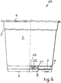
- FIG. 1 to 4 A total of 1 designated plant pot has a common, substantially frusto-conical basic shape with a wall 2, which is issued and stiffened at the top once again by a narrow ledge 3 and merges into an outwardly projecting edge 4.
- a bottom 5 On the underside, a bottom 5 is placed over edge webs 6.
- T-shaped web extensions are arranged under a flat peripheral region 9 of the bottom 5 as erection feet. So far off Fig.
- the web extensions 8 are formed slightly shortened, which already takes into account a certain sagging of the soil after filling the pot and in any case, a rising of the pot 1 is ensured on the edge webs 6.
- a ring of holes for the water outlet is arranged, wherein the webs 7 and 8 respectively with oblique discharge edges are brought to the holes 10, 11 and 12, respectively, to allow as complete a water drainage and to avoid hanging drops.
- the holes 10, 11, 12 are particularly low-lying with the peripheral region 9 and accordingly for the (complete) drainage particularly important.
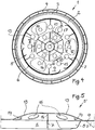
- a flat dome 13 is arched to reliably settle the soil from a footprint for the plant pot 1, even if it lowers by filling the pot.
- a conventional flat dome design has been found to be unreliable, since large loads can be caused by a vigorous manual or machine filling of the plant pot or even insertion of support rods or the like into the plant pot to cause the dome to sag.
- the dome 13 is stiffened star-shaped in the plant pot 1 by profile struts 14, which extend as beams from a central region to the peripheral region 9.
- profile struts 14 set as upright webs on each side of the dome 13 and extend horizontally or flat to the height of the peripheral portion 9 sloping towards this.
- On the inside they abut on a depression 15 of the dome 13, which does not quite down to the height of the peripheral portion 9, but down to the height of the lower edges of the profile struts 14 and this also connects with each other.
- the dome 13 still has between the profile struts 14 drainage holes 16, of course, too contribute to the ventilation of the plant pot and root ball contained therein.
- the depression 15 is also provided with a drainage hole 17.
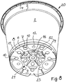
- the inventive embodiment of the plant pot consists in a plant pot 20, as in the Fig. 6 to 10 is illustrated. This embodiment is deviating only in the design of a dome 21 together with star-shaped profile struts 22 of the above-described plant pot 1, so that matching parts of the above-described plant pot are also marked with matching reference numbers.
- the dome 21 is not stiffened by simple, upstanding webs as profile struts 14 but through the top open hollow sections 22.
- the dome shape is interrupted and divided into segments 23, between which the shell surfaces of the dome 21 respectively in the top open hollow profile 22 pass.
- the profile webs 22 are V-shaped with a lower edge which lies approximately at the level of the peripheral region 9 or slightly sloping to the peripheral region 9. To this peripheral region 9 run the profile webs 22, quite corresponding to the profile webs 14, from. On the inside, the profile webs 22 merge into the peripheral wall of a depression 24 that corresponds in its basic form to the depression 15 of the first embodiment described, wherein each hollow profile of the profile webs 22 opens open into the depression 24 in the sense of an unbranched shell shape.
- Such a design with hollow profiles 22 and segmentally intermediate dome regions is not only in the injection molding process but also in the deep-drawing process executable.
- the footbridges are also available as hollow profiles or - to perform nubs.
Landscapes
- Life Sciences & Earth Sciences (AREA)
- Environmental Sciences (AREA)
- Cultivation Receptacles Or Flower-Pots, Or Pots For Seedlings (AREA)
Description
- Die Erfindung betrifft einen Pflanztopf aus Kunststoff nach dem Oberbegriff des Anspruchs 1.
- Pflanztöpfe dieser Art sind für den Erwerbsgartenbau allgemein mit einem Boden versehen, der Öffnungen für eine effektive Entwässerung auch bei zeitweilig überschüssiger Bewässerung sorgt und unterseitig einen Abstand gegenüber einer Aufstellfläche zum Wasserablauf und zur Belüftung einhält. Eine Schwallbewässerung mittels Brausebewässerung von oben oder eine sogenannte "Ebbe- und Flut-Bewässerung", bei der die Pflanztöpfe von Zeit zu Zeit von unten geflutet werden, sorgt zunächst für einen über den Feuchtigkeitsbedarf hinausgehenden Wassereintrag, der sich durch den Ablauf überschüssigen Wassers reduziert. Zur Vermeidung von Staunässe ist insbesondere ein bodenseitiger Wasserablauf auch dann sicherzustellen, wenn der Pflanztopf auf einer wasserbenetzten oder sogar mit Wasserlachen versehenen Aufstellfläche steht. Dies ist typischerweise in Betracht zu ziehen, wenn die Pflanztöpfe auf Betonböden angeordnet sind, die bei überschüssiger Bewässerung in Bodenunebenheiten Pfützen bilden.
- Da die Pflanztöpfe für den Erwerbsgartenbau aus Gründen der Kosten- und Materialersparnis dünnwandig ausgebildet werden und da der Boden solcher Pflanztöpfe aufgrund von Befüllung, Bepflanzung oder Wurzeldruck nach unten hin durchhängen kann, hat man bereits die Böden derartiger Pflanztöpfe zumindest in einem inneren Teilbereich kuppelartig ; aufgewölbt, siehe z.B. die Offenbarungen
NL-C2-1020443 DE 20109317 U1 . Außenliegende Bereiche des Boden sind dabei durch die angrenzende Wandung stabilisiert und meist auch noch durch Fortsätze wie Randstege oder Noppen hochgestellt. Die Aufwölbungen sind relativ flach zu halten, um wenig an Topfraum preiszugeben und nicht etwa zerklüftete Randbereiche im Topf zu schaffen. Dies führt allerdings auch dazu, dass bei einer nachdrücklichen Befüllung des Topfes mit Substrat und dgl. Material und insbesondere auch beim Einstecken von Rankstäben und dgl. ein unerwünschtes Durchdrücken und Durchbeulen eintreten kann. Damit wird dann die Entwässerung und die Standfestigkeit des Pflanztopfs hinfällig. - Aufgabe der Erfindung ist es dementsprechend, einen Pflanztopf mit einem Boden zu schaffen, der in herkömmlicher Weise dünnwandig ausgebildet und mit gebräuchlichen großserientechnischen Mitteln hergestellt werden kann, der aber eine gegen ein Durchdrücken und Durchbeulen gesicherten Bodenbereich in Form einer aufgewölbten Kuppel aufweist.
- Gemäß der Erfindung wird diese Aufgabe von einem Pflanztopf nach dem Oberbegriff des Anspruchs 1 ausgehend mit dessen kennzeichnenden Merkmalen gelöst. Mit den Profilstreben läßt sich die Kuppelform erheblich versteifen und gegen ein Durchbeulen nach unten absichern. Druckkräfte auf die Kuppel und den sonstigen Boden, die etwa beim Einfüllen von Pflanzsubstrat, beim Einsetzen von Pflanzen oder auch - mehr punktuell - beim Einstecken von Rankstäben oder Stützstäben für die Pflanzen auf-treten, werden nur zu einem geringeren Teil durch Beul- und Biegekräfte innerhalb der Kuppelschale, im Wesentlichen als Zugkräfte (Längskräfte) von den Profilstreben aufgenommen. Diese leiten die entsprechenden Kräfte als Längskräfte zu den Umfangsbereichen ab, die durch die Wandung des Pflanztopfs von Haus aus ausgesteift sind.
- Die Profilstreben sind als oberseitig offene Hohlprofile ausgebildet, die zwischen Sektoren der Kuppel eingeformt sind. Es ergibt sich dann eine durchgängige Schalenform mit als Hohlprofil eingeformten Profilstreben. Eine solche Ausführungsform ist in Großserie sowohl bei spritzgußgeformten wie auch tiefgezogenen Pflanztöpfen verwendbar.
- Zweckmäßig kann die Kuppel punktsymmetrisch bezüglich des mittleren Bereichs ausgestaltet sein, so dass die Profilstreben radial oder jedenfalls punktsymmetrisch verlaufen. Der mittlere Bereich kann als Einsenkung bis auf die Höhe der Profilstreben ausgebildet werden, um einerseits die Profilstreben zentral miteinander in einer Höhe zu verbinden, andererseits auch in Verbindung mit einem Loch mit mehreren Löchern einen Wasserablauf herzustellen.
- Zwei Ausführungsbeispiele sind in der Zeichnung dargestellt und werden nachfolgend näher beschrieben. In der Zeichnung zeigen:
-
Fig. 1 Seitenansicht eines nicht-erfindungsgemäßen Pflanztopfs, zur Hälfte als Schnitt, -
Fig. 2 Ansicht des Pflanztopfs schräg von oben, -
Fig. 3 Ansicht des Pflanztopfs schräg von unten, -
Fig. 4 Unteransicht des Pflanztopfs und -
Fig. 5 Schnitt nach V - V inFig. 4 , im Maßstab 2 : 1 vergrößert, -
Fig. 6 Seitenansicht einer erfindungsgemäßen Ausführungsform eines Pflanztopfs, - zur Hälfte als Schnitt,
-
Fig. 7 Ansicht des Pflanztopfs nachFig. 6 schräg von oben, -
Fig. 8 Ansicht des Pflanztopfs nachFig. 6 und7 schräg von unten -
Fig. 9 Unteransicht des Pflanztopfs nachFig. 6 bis 9 -
Fig. 10 Schnitt nach Linie X - X inFig. 8 , im Maßstab 2 : 1 vergrößert. - Ein in
Fig. 1 bis 4 insgesamt 1 bezeichneter Pflanztopf hat eine gebräuchliche, im wesentlichen kegelstumpfförmige Grundform mit einer Wandung 2, die nach oben hin noch einmal durch einen schmalen Sims 3 ausgestellt und ausgesteift ist und in einen nach außen ragenden Rand 4 übergeht. Unterseitig ist ein Boden 5 über Randstege 6 aufgestellt. Weitere stegartige Fortsätze 7, die mit den Randstegen 6 rechtwinklig verbunden sind und diese innenseitig abstützen, verlaufen vorwiegend radial unter dem Boden 5. T-förmige Stegfortsätze sind unter einem flachen Umfangsbereich 9 des Bodens 5 als Aufstellfüße angeordnet. Soweit ausFig. 1 noch ersichtlich ist, dass die Stegfortsätze 8 leicht verkürzt ausgebildet sind, womit bereits ein gewisses Durch-hängen des Bodens nach dem Befüllen des Topfes berücksichtigt und in jedem Fall auch ein Aufstehen des Topfes 1 auf den Randstegen 6 gewährleistet wird. In dem flachen Umfangsbereich 9 ist ein Kranz von Löchern für den Wasserablauf angeordnet, wobei die Stege 7 und 8 jeweils mit schrägen Ablaufkanten an die Löcher 10, 11 bzw. 12 herangeführt sind, um einen möglichst vollständigen Wasserablauf zu ermöglichen und hängende Tropfen zu vermeiden. Die Löcher 10, 11, 12 sind mit dem Umfangsbereich 9 besonders tiefliegend und dementsprechend für die (vollständige) Entwässerung besonders wichtig. - In einem mittleren Bereich des Bodens 5 ist eine flache Kuppel 13 hochgewölbt, um den Boden auch dann verlässlich von einer Aufstellfläche für den Pflanztopf 1 abzusetzen, wenn sich dieser durch Befüllung des Topfes absenkt. Allerdings hat sich eine herkömmliche Ausgestaltung mit einer flachen Kuppel als unzuverlässig herausgestellt, da große Belastungen durch ein mit Nachdruck erfolgendes manuelles oder maschinelles Befüllen des Pflanztopfs oder auch ein Einstecken von Stützstäben oder dgl. in den Pflanztopf zu einem Durchbeulen der Kuppel nach unten führen kann.
- Dem wird wirkungsvoll dadurch abgeholfen, dass die Kuppel 13 bei dem Pflanztopf 1 durch Profilstreben 14 sternförmig ausgesteift ist, die als Unterzüge aus einem mittleren Bereich zum Umfangsbereich 9 verlaufen. Diese Profilstreben 14 setzen als aufrechte Stege unterseitig jeweils an der Kuppel 13 an und erstrecken sich horizontal bzw. flach auf die Höhe des Umfangsbereichs 9 abfallend zu diesem hin. Innenseitig stoßen sie an eine Einsenkung 15 der Kuppel 13 an, die hier nicht ganz auf die Höhe des Umfangsbereichs 9, aber auf die Höhe der Unterkanten der Profilstreben 14 herunterführt und diese auch untereinander verbindet. Damit ist eine hohe Belastbarkeit der Kuppel 13 gewonnen. Die Kuppel 13 weist noch zwischen den Profilstreben 14 Entwässerungslöcher 16 auf, die natürlich auch zur Belüftung des Pflanztopfs und darin enthaltener Wurzelballen beitragen. Auch die Einsenkung 15 ist mit einem Entwässerungsloch 17 versehen. Die erfindungsgemäße Ausführungsform des Pflanztopfs besteht in einem Pflanze topf 20, wie er in den
Fig. 6 bis 10 veranschaulicht ist. Diese Ausführungsform ist lediglich in der Gestaltung einer Kuppel 21 mitsamt sternförmig angeordneten Profilstreben 22 von dem vorbeschriebenen Pflanztopf 1 abweichend, so dass übereinstimmende Teile des vorbeschriebenen Pflanztopfs auch mit übereinstimmenden Bezugsnummern gekennzeichnet sind. Bei dem Pflanztopf 20 wird die Kuppel 21 nicht durch einfache, hochkant stehende Stege als Profilstreben 14 ausgesteift sondern durch die oberseitig offenen Hohlprofile 22. Damit wird auch die Kuppelform unterbrochen und in Segmente 23 unterteilt, zwischen denen die Schalenflächen der Kuppel 21 jeweils in das oberseitig offene Hohlprofil 22 übergehen. Die Profilstege 22 sind V-förmig ausgebildet mit einer Unterkante, die etwa in Höhe des Umfangsbereichs 9 bzw. leicht zum Umfangsbereich 9 abfallend liegt. Zu diesem Umfangsbereich 9 laufen die Profilstege 22, ganz entsprechend den Profilstegen 14, aus. Innenseitig gehen die Profilstege 22 in die Umfangswand einer in der Grundform mit der Einsenkung 15 der erstbeschriebenen Ausführungsform übereinstimmende Einsenkung 24 über, wobei je-des Hohlprofil der Profilstege 22 offen in die Einsenkung 24 im Sinne einer unverzweigten Schalenform einmündet. - Eine solche Gestaltung mit Hohlprofilen 22 und mit segmentförmig zwischenliegenden Kuppelbereichen ist nicht nur im Spritzgußverfahren sondern auch im Tiefziehverfahren ausführbar. Die Fußstege sind dann allerdings auch als Hohlprofile oder - noppen auszuführen. Sie ermöglicht es aber in gleicher Weise wie die Gestaltung des erstbeschriebenen Pflanztopfs, mit den als Unterzügen wirkenden Profilstreben die Kuppel so zu versteifen, dass ein Durchbeulen in der Praxis ausgeschlossen werden kann.
- Beide Gestaltungen sind für die Serienfertigung ohne größeren Aufwand in der Formherstellung und im Formgebungsverfahren und auch ohne größeren Materialaufwand zu realisieren, räumen aber eine Schwäche herkömmlicher Pflanztöpfe dieser Art und die damit einhergehenden Störungsanfälligkeiten aus.
Claims (9)
- Pflanztopf (20) aus Kunststoff mit einer vorwiegend vertikal ausgerichteten
Wandung (2) und einem vorwiegend horizontal ausgerichteten und randseitig mit der Wandung (2) verbundenen Boden (5), der zumindest in einem inneren Teilbereich in Form einer Kuppel (21) aufgewölbt ist, wobei die Kuppel (21) durch Profilstreben (22) ausgesteift ist, dadurch gekennzeichnet, dass die Profilstreben (22) als Unterzüge aus einem mittleren Bereich (24) der Kuppel (21) zu zumindest Umfangsbereichen (9) der Kuppel (21) verlaufen, und als oberseitig offene Hohlprofile ausgebildet sind, die zwischen Sektoren (23) der Kuppel (21) eingeformt sind. - Pflanztopf nach Anspruch 1, dadurch gekennzeichnet, dass die Kuppel (21) punktsymmetrisch bezüglich des mittleren Bereichs (24) gestaltet ist.
- Pflanztopf nach Anspruch 1 oder 2, dadurch gekennzeichnet, dass der mittlere Bereich als Einsenkung (24) in der Kuppel (21) in Höhe der Profilstreben (22) ausgebildet ist.
- Pflanztopf nach Anspruch 3, dadurch gekennzeichnet, dass die Einsenkung (24) mit zumindest einem Loch (17) versehen ist.
- Pflanztopf nach einem der Ansprüche 1 bis 4, dadurch gekennzeichnet, dass der Boden (5) zwischen der Kuppel (21) und der Wandung (2) einen im wesentlichen flachen Umfangsbereich (9) aufweist, in den die Profilstreben (22) auslaufen.
- Pflanztopf nach Anspruch 5, dadurch gekennzeichnet, dass der Boden (5) im Außenbereich mit Löchern (10, 11, 12) versehen ist.
- Pflanztopf nach einem der Ansprüche 1 bis 6, dadurch gekennzeichnet, dass der Boden (5) unterseitig mit Fußfortsätzen (6, 7, 8) zum Aufstellen ausgestattet ist.
- Pflanztopf nach Anspruch 7 in Verbindung mit Anspruch 6, dadurch gekennzeichnet, dass die Fußfortsätze (6, 7, 8) zumindest randseitig an Löcher (10, 11, 12) herangeführt sind.
- Pflanztopf nach Anspruch 8, dadurch gekennzeichnet, dass die Fußfortsätze (6, 7, 8) als Stege unterseitig am Boden angesetzt sind.
Priority Applications (1)
| Application Number | Priority Date | Filing Date | Title |
|---|---|---|---|
| PL08838418T PL2197262T3 (pl) | 2007-10-08 | 2008-09-19 | Doniczka na rośliny z tworzywa sztucznego |
Applications Claiming Priority (2)
| Application Number | Priority Date | Filing Date | Title |
|---|---|---|---|
| DE202007014037U DE202007014037U1 (de) | 2007-10-08 | 2007-10-08 | Pflanztopf aus Kunststoff |
| PCT/EP2008/007863 WO2009046838A2 (de) | 2007-10-08 | 2008-09-19 | Pflanztopf aus kunststoff |
Publications (2)
| Publication Number | Publication Date |
|---|---|
| EP2197262A2 EP2197262A2 (de) | 2010-06-23 |
| EP2197262B1 true EP2197262B1 (de) | 2018-05-16 |
Family
ID=40458539
Family Applications (1)
| Application Number | Title | Priority Date | Filing Date |
|---|---|---|---|
| EP08838418.5A Active EP2197262B1 (de) | 2007-10-08 | 2008-09-19 | Pflanztopf aus kunststoff |
Country Status (6)
| Country | Link |
|---|---|
| US (1) | US8510987B2 (de) |
| EP (1) | EP2197262B1 (de) |
| DE (1) | DE202007014037U1 (de) |
| DK (1) | DK2197262T3 (de) |
| PL (1) | PL2197262T3 (de) |
| WO (1) | WO2009046838A2 (de) |
Families Citing this family (9)
| Publication number | Priority date | Publication date | Assignee | Title |
|---|---|---|---|---|
| NL2004344C2 (nl) * | 2010-03-05 | 2011-09-06 | Voskamp Vollebregt Holding B V | Plantpot, alsmede combinatie van meerdere plantpotten. |
| CA2903070C (en) * | 2013-03-04 | 2021-02-16 | Poppin Pods Australia Pty Ltd | Living plant display and storage system, apparatus and method |
| NL2011041C2 (nl) * | 2013-06-26 | 2015-01-05 | Desch Plantpak B V | Plantenpot. |
| US10076085B2 (en) * | 2015-01-26 | 2018-09-18 | Plantlogic LLC | Stackable pots for plants |
| US10687479B2 (en) * | 2016-01-27 | 2020-06-23 | Plantlogic, LLC | Drainage collection pots for plants |
| CA3241828A1 (en) * | 2017-02-27 | 2018-08-27 | The Hc Companies, Inc. | Horticultural container with tag slot |
| US20200113356A1 (en) * | 2017-06-27 | 2020-04-16 | Mark Talerico | Tool for handling hanging basket |
| DE202023105005U1 (de) | 2023-09-01 | 2024-12-17 | Pöppelmann Holding GmbH & Co. KG | Pflanztopf mit Entwässserungsstreben |
| USD1037916S1 (en) * | 2024-02-26 | 2024-08-06 | Shenzhen Aichong Industry Co., Ltd | Plant pot |
Citations (1)
| Publication number | Priority date | Publication date | Assignee | Title |
|---|---|---|---|---|
| DE20109317U1 (de) * | 2000-06-02 | 2001-09-27 | Interco V.O.F., Delier | Pflanzentopf mit entwässerndem Boden |
Family Cites Families (18)
| Publication number | Priority date | Publication date | Assignee | Title |
|---|---|---|---|---|
| US296028A (en) * | 1884-04-01 | Flower-pot | ||
| US2550989A (en) * | 1949-04-01 | 1951-05-01 | Newton L French | Detachable plate or dish retainer |
| US2770957A (en) * | 1954-09-27 | 1956-11-20 | Earl D Bronson | Drip-preventing saucer |
| US4057931A (en) * | 1974-11-20 | 1977-11-15 | National Polymers, Inc. | Stackable flower pot |
| US5269095A (en) * | 1991-07-11 | 1993-12-14 | Topsiders, Inc. | Planter mounting assembly |
| US5761848A (en) * | 1993-09-15 | 1998-06-09 | Manlove; Steve | Nursery container |
| NL9500175A (nl) * | 1995-02-01 | 1996-09-02 | Synprodo Hortiproducts Bv | Bloempot. |
| US6134832A (en) * | 1999-04-27 | 2000-10-24 | Landmark Plastic Corporation | Nest and stack plant pot |
| DE29918043U1 (de) * | 1999-10-12 | 2000-02-10 | Gebr. Pöppelmann, Kunststoffwerk-Werkzeugbau, 49393 Lohne | Pflanztopf aus tiefgezogener Kunststoffolie |
| JP2001299098A (ja) * | 2000-02-14 | 2001-10-30 | Yoshihiro Terada | 植木鉢 |
| US6955008B2 (en) * | 2000-06-09 | 2005-10-18 | Rose Andrew D | Aerating base plate for a flowerpot |
| DE20119165U1 (de) * | 2001-11-26 | 2003-03-06 | Gebr. Pöppelmann, Kunststoffwerk-Werkzeugbau, 49393 Lohne | Pflanztopf aus Kunststoff |
| US6766615B2 (en) * | 2002-01-24 | 2004-07-27 | California Plastic Products | Root saving plant saucer |
| NL1020443C2 (nl) * | 2002-04-22 | 2003-10-23 | Aufderhaar Plastic Ind B V | Houder voor gewassen met neerwaarts hellend bodemdeel voorzien van afwateringsgaten. |
| US7454864B2 (en) * | 2003-04-25 | 2008-11-25 | Smith Thomas J | Planting pots and multi-compartment tray having self-orienting configuration |
| US7024818B2 (en) * | 2003-09-05 | 2006-04-11 | Maniscalco Kristine A | False bottom insert assembly for an oversized planter container |
| DE202005012314U1 (de) * | 2005-08-05 | 2006-03-02 | Pöppelmann Holding GmbH & Co. KG | Kunststoffbehälter |
| US20080276530A1 (en) * | 2007-05-10 | 2008-11-13 | Grzegorz Trabka To Ball Horticultural Company | Multi-pot container |
-
2007
- 2007-10-08 DE DE202007014037U patent/DE202007014037U1/de not_active Expired - Lifetime
-
2008
- 2008-09-19 DK DK08838418.5T patent/DK2197262T3/en active
- 2008-09-19 WO PCT/EP2008/007863 patent/WO2009046838A2/de not_active Ceased
- 2008-09-19 PL PL08838418T patent/PL2197262T3/pl unknown
- 2008-09-19 US US12/673,873 patent/US8510987B2/en not_active Expired - Fee Related
- 2008-09-19 EP EP08838418.5A patent/EP2197262B1/de active Active
Patent Citations (1)
| Publication number | Priority date | Publication date | Assignee | Title |
|---|---|---|---|---|
| DE20109317U1 (de) * | 2000-06-02 | 2001-09-27 | Interco V.O.F., Delier | Pflanzentopf mit entwässerndem Boden |
Also Published As
| Publication number | Publication date |
|---|---|
| US20110036003A1 (en) | 2011-02-17 |
| DK2197262T3 (en) | 2018-07-16 |
| WO2009046838A2 (de) | 2009-04-16 |
| PL2197262T3 (pl) | 2018-08-31 |
| DE202007014037U1 (de) | 2009-03-19 |
| US8510987B2 (en) | 2013-08-20 |
| WO2009046838A3 (de) | 2009-06-18 |
| EP2197262A2 (de) | 2010-06-23 |
Similar Documents
| Publication | Publication Date | Title |
|---|---|---|
| EP2197262B1 (de) | Pflanztopf aus kunststoff | |
| EP2291070B1 (de) | Pflanztopf | |
| EP1448044B1 (de) | Pflanztopf aus kunststoff | |
| DE2048551A1 (de) | Bauelement fur Wände, Gitter wände oder dergleichen | |
| DE102004007424A1 (de) | Bausatz für die Konstruktion des oberen Randes und der Überlaufrinne in Schwimmbecken mit Überlaufrinne | |
| DE69628084T2 (de) | Verteiler für Flüssigkeiten | |
| EP1291325A2 (de) | Rinnenabschnitt zur Herstellung einer Rinne zur Aufnahme von Oberflächenwasser | |
| AT500578B1 (de) | Rinnensystem | |
| DE3490714T (de) | Blumentopf | |
| DE9308335U1 (de) | Pflanztopf | |
| DE202018106835U1 (de) | Pflanztopf mit Bewässerungssystem | |
| DE3906121C2 (de) | Pflanzenkübel für Dekorationszwecke an einem Pfahl oder Pfosten | |
| DE4134800C1 (en) | Recycled plastics sound barrier wall - has triangular cross=section with pockets to receive plants | |
| DE9308219U1 (de) | Stapelbarer Pflanzentopf | |
| DE202019106331U1 (de) | Dachfläche eines Bauwerks | |
| DE8710405U1 (de) | Lärmschutzwand | |
| CH709249A2 (de) | Pflanzbeet-Vorrichtung. | |
| DE102019132124B4 (de) | Bausatz zur Montage eines bepflanzbaren Wandgartens | |
| DE29821501U1 (de) | Pflanztopf | |
| AT344957B (de) | Plattenfoermiges bauelement | |
| DE9310462U1 (de) | Wannenträger | |
| DE202021102145U1 (de) | Zaunmodul | |
| DE2750729A1 (de) | Verbesserter dachraumluefter | |
| WO2025224199A1 (de) | Aufsatzbehältervorrichtung und deren verwendung | |
| DE202014002203U1 (de) | Pflanzenkastenanordnung |
Legal Events
| Date | Code | Title | Description |
|---|---|---|---|
| PUAI | Public reference made under article 153(3) epc to a published international application that has entered the european phase |
Free format text: ORIGINAL CODE: 0009012 |
|
| 17P | Request for examination filed |
Effective date: 20100108 |
|
| AK | Designated contracting states |
Kind code of ref document: A2 Designated state(s): AT BE BG CH CY CZ DE DK EE ES FI FR GB GR HR HU IE IS IT LI LT LU LV MC MT NL NO PL PT RO SE SI SK TR |
|
| AX | Request for extension of the european patent |
Extension state: AL BA MK RS |
|
| DAX | Request for extension of the european patent (deleted) | ||
| 17Q | First examination report despatched |
Effective date: 20160601 |
|
| GRAP | Despatch of communication of intention to grant a patent |
Free format text: ORIGINAL CODE: EPIDOSNIGR1 |
|
| STAA | Information on the status of an ep patent application or granted ep patent |
Free format text: STATUS: GRANT OF PATENT IS INTENDED |
|
| INTG | Intention to grant announced |
Effective date: 20180209 |
|
| GRAS | Grant fee paid |
Free format text: ORIGINAL CODE: EPIDOSNIGR3 |
|
| GRAA | (expected) grant |
Free format text: ORIGINAL CODE: 0009210 |
|
| STAA | Information on the status of an ep patent application or granted ep patent |
Free format text: STATUS: THE PATENT HAS BEEN GRANTED |
|
| AK | Designated contracting states |
Kind code of ref document: B1 Designated state(s): AT BE BG CH CY CZ DE DK EE ES FI FR GB GR HR HU IE IS IT LI LT LU LV MC MT NL NO PL PT RO SE SI SK TR |
|
| REG | Reference to a national code |
Ref country code: GB Ref legal event code: FG4D Free format text: NOT ENGLISH |
|
| REG | Reference to a national code |
Ref country code: CH Ref legal event code: EP |
|
| REG | Reference to a national code |
Ref country code: DE Ref legal event code: R096 Ref document number: 502008016086 Country of ref document: DE |
|
| REG | Reference to a national code |
Ref country code: IE Ref legal event code: FG4D Free format text: LANGUAGE OF EP DOCUMENT: GERMAN |
|
| REG | Reference to a national code |
Ref country code: AT Ref legal event code: REF Ref document number: 998696 Country of ref document: AT Kind code of ref document: T Effective date: 20180615 |
|
| REG | Reference to a national code |
Ref country code: DK Ref legal event code: T3 Effective date: 20180709 |
|
| REG | Reference to a national code |
Ref country code: NL Ref legal event code: FP |
|
| REG | Reference to a national code |
Ref country code: FR Ref legal event code: PLFP Year of fee payment: 11 |
|
| REG | Reference to a national code |
Ref country code: LT Ref legal event code: MG4D |
|
| PG25 | Lapsed in a contracting state [announced via postgrant information from national office to epo] |
Ref country code: ES Free format text: LAPSE BECAUSE OF FAILURE TO SUBMIT A TRANSLATION OF THE DESCRIPTION OR TO PAY THE FEE WITHIN THE PRESCRIBED TIME-LIMIT Effective date: 20180516 Ref country code: SE Free format text: LAPSE BECAUSE OF FAILURE TO SUBMIT A TRANSLATION OF THE DESCRIPTION OR TO PAY THE FEE WITHIN THE PRESCRIBED TIME-LIMIT Effective date: 20180516 Ref country code: LT Free format text: LAPSE BECAUSE OF FAILURE TO SUBMIT A TRANSLATION OF THE DESCRIPTION OR TO PAY THE FEE WITHIN THE PRESCRIBED TIME-LIMIT Effective date: 20180516 Ref country code: NO Free format text: LAPSE BECAUSE OF FAILURE TO SUBMIT A TRANSLATION OF THE DESCRIPTION OR TO PAY THE FEE WITHIN THE PRESCRIBED TIME-LIMIT Effective date: 20180816 Ref country code: FI Free format text: LAPSE BECAUSE OF FAILURE TO SUBMIT A TRANSLATION OF THE DESCRIPTION OR TO PAY THE FEE WITHIN THE PRESCRIBED TIME-LIMIT Effective date: 20180516 Ref country code: BG Free format text: LAPSE BECAUSE OF FAILURE TO SUBMIT A TRANSLATION OF THE DESCRIPTION OR TO PAY THE FEE WITHIN THE PRESCRIBED TIME-LIMIT Effective date: 20180816 |
|
| PG25 | Lapsed in a contracting state [announced via postgrant information from national office to epo] |
Ref country code: LV Free format text: LAPSE BECAUSE OF FAILURE TO SUBMIT A TRANSLATION OF THE DESCRIPTION OR TO PAY THE FEE WITHIN THE PRESCRIBED TIME-LIMIT Effective date: 20180516 Ref country code: GR Free format text: LAPSE BECAUSE OF FAILURE TO SUBMIT A TRANSLATION OF THE DESCRIPTION OR TO PAY THE FEE WITHIN THE PRESCRIBED TIME-LIMIT Effective date: 20180817 Ref country code: HR Free format text: LAPSE BECAUSE OF FAILURE TO SUBMIT A TRANSLATION OF THE DESCRIPTION OR TO PAY THE FEE WITHIN THE PRESCRIBED TIME-LIMIT Effective date: 20180516 |
|
| PG25 | Lapsed in a contracting state [announced via postgrant information from national office to epo] |
Ref country code: CZ Free format text: LAPSE BECAUSE OF FAILURE TO SUBMIT A TRANSLATION OF THE DESCRIPTION OR TO PAY THE FEE WITHIN THE PRESCRIBED TIME-LIMIT Effective date: 20180516 Ref country code: SK Free format text: LAPSE BECAUSE OF FAILURE TO SUBMIT A TRANSLATION OF THE DESCRIPTION OR TO PAY THE FEE WITHIN THE PRESCRIBED TIME-LIMIT Effective date: 20180516 Ref country code: EE Free format text: LAPSE BECAUSE OF FAILURE TO SUBMIT A TRANSLATION OF THE DESCRIPTION OR TO PAY THE FEE WITHIN THE PRESCRIBED TIME-LIMIT Effective date: 20180516 Ref country code: RO Free format text: LAPSE BECAUSE OF FAILURE TO SUBMIT A TRANSLATION OF THE DESCRIPTION OR TO PAY THE FEE WITHIN THE PRESCRIBED TIME-LIMIT Effective date: 20180516 |
|
| REG | Reference to a national code |
Ref country code: DE Ref legal event code: R097 Ref document number: 502008016086 Country of ref document: DE |
|
| PLBE | No opposition filed within time limit |
Free format text: ORIGINAL CODE: 0009261 |
|
| STAA | Information on the status of an ep patent application or granted ep patent |
Free format text: STATUS: NO OPPOSITION FILED WITHIN TIME LIMIT |
|
| 26N | No opposition filed |
Effective date: 20190219 |
|
| PG25 | Lapsed in a contracting state [announced via postgrant information from national office to epo] |
Ref country code: MC Free format text: LAPSE BECAUSE OF FAILURE TO SUBMIT A TRANSLATION OF THE DESCRIPTION OR TO PAY THE FEE WITHIN THE PRESCRIBED TIME-LIMIT Effective date: 20180516 |
|
| REG | Reference to a national code |
Ref country code: CH Ref legal event code: PL |
|
| PG25 | Lapsed in a contracting state [announced via postgrant information from national office to epo] |
Ref country code: SI Free format text: LAPSE BECAUSE OF FAILURE TO SUBMIT A TRANSLATION OF THE DESCRIPTION OR TO PAY THE FEE WITHIN THE PRESCRIBED TIME-LIMIT Effective date: 20180516 |
|
| REG | Reference to a national code |
Ref country code: BE Ref legal event code: MM Effective date: 20180930 |
|
| REG | Reference to a national code |
Ref country code: IE Ref legal event code: MM4A |
|
| PG25 | Lapsed in a contracting state [announced via postgrant information from national office to epo] |
Ref country code: LU Free format text: LAPSE BECAUSE OF NON-PAYMENT OF DUE FEES Effective date: 20180919 |
|
| PG25 | Lapsed in a contracting state [announced via postgrant information from national office to epo] |
Ref country code: IE Free format text: LAPSE BECAUSE OF NON-PAYMENT OF DUE FEES Effective date: 20180919 |
|
| PG25 | Lapsed in a contracting state [announced via postgrant information from national office to epo] |
Ref country code: CH Free format text: LAPSE BECAUSE OF NON-PAYMENT OF DUE FEES Effective date: 20180930 Ref country code: LI Free format text: LAPSE BECAUSE OF NON-PAYMENT OF DUE FEES Effective date: 20180930 Ref country code: BE Free format text: LAPSE BECAUSE OF NON-PAYMENT OF DUE FEES Effective date: 20180930 |
|
| REG | Reference to a national code |
Ref country code: AT Ref legal event code: MM01 Ref document number: 998696 Country of ref document: AT Kind code of ref document: T Effective date: 20180919 |
|
| PG25 | Lapsed in a contracting state [announced via postgrant information from national office to epo] |
Ref country code: MT Free format text: LAPSE BECAUSE OF FAILURE TO SUBMIT A TRANSLATION OF THE DESCRIPTION OR TO PAY THE FEE WITHIN THE PRESCRIBED TIME-LIMIT Effective date: 20180516 Ref country code: AT Free format text: LAPSE BECAUSE OF NON-PAYMENT OF DUE FEES Effective date: 20180919 |
|
| PG25 | Lapsed in a contracting state [announced via postgrant information from national office to epo] |
Ref country code: TR Free format text: LAPSE BECAUSE OF FAILURE TO SUBMIT A TRANSLATION OF THE DESCRIPTION OR TO PAY THE FEE WITHIN THE PRESCRIBED TIME-LIMIT Effective date: 20180516 |
|
| PG25 | Lapsed in a contracting state [announced via postgrant information from national office to epo] |
Ref country code: PT Free format text: LAPSE BECAUSE OF FAILURE TO SUBMIT A TRANSLATION OF THE DESCRIPTION OR TO PAY THE FEE WITHIN THE PRESCRIBED TIME-LIMIT Effective date: 20180516 Ref country code: HU Free format text: LAPSE BECAUSE OF FAILURE TO SUBMIT A TRANSLATION OF THE DESCRIPTION OR TO PAY THE FEE WITHIN THE PRESCRIBED TIME-LIMIT; INVALID AB INITIO Effective date: 20080919 |
|
| PG25 | Lapsed in a contracting state [announced via postgrant information from national office to epo] |
Ref country code: CY Free format text: LAPSE BECAUSE OF FAILURE TO SUBMIT A TRANSLATION OF THE DESCRIPTION OR TO PAY THE FEE WITHIN THE PRESCRIBED TIME-LIMIT Effective date: 20180516 |
|
| PG25 | Lapsed in a contracting state [announced via postgrant information from national office to epo] |
Ref country code: IS Free format text: LAPSE BECAUSE OF FAILURE TO SUBMIT A TRANSLATION OF THE DESCRIPTION OR TO PAY THE FEE WITHIN THE PRESCRIBED TIME-LIMIT Effective date: 20180916 |
|
| PGFP | Annual fee paid to national office [announced via postgrant information from national office to epo] |
Ref country code: GB Payment date: 20230921 Year of fee payment: 16 |
|
| PGFP | Annual fee paid to national office [announced via postgrant information from national office to epo] |
Ref country code: PL Payment date: 20230911 Year of fee payment: 16 Ref country code: FR Payment date: 20230918 Year of fee payment: 16 Ref country code: DK Payment date: 20230921 Year of fee payment: 16 |
|
| PGFP | Annual fee paid to national office [announced via postgrant information from national office to epo] |
Ref country code: IT Payment date: 20230929 Year of fee payment: 16 |
|
| REG | Reference to a national code |
Ref country code: DK Ref legal event code: EBP Effective date: 20240930 |
|
| GBPC | Gb: european patent ceased through non-payment of renewal fee |
Effective date: 20240919 |
|
| PG25 | Lapsed in a contracting state [announced via postgrant information from national office to epo] |
Ref country code: GB Free format text: LAPSE BECAUSE OF NON-PAYMENT OF DUE FEES Effective date: 20240919 |
|
| PG25 | Lapsed in a contracting state [announced via postgrant information from national office to epo] |
Ref country code: IT Free format text: LAPSE BECAUSE OF NON-PAYMENT OF DUE FEES Effective date: 20240919 |
|
| PG25 | Lapsed in a contracting state [announced via postgrant information from national office to epo] |
Ref country code: FR Free format text: LAPSE BECAUSE OF NON-PAYMENT OF DUE FEES Effective date: 20240930 |
|
| PG25 | Lapsed in a contracting state [announced via postgrant information from national office to epo] |
Ref country code: DK Free format text: LAPSE BECAUSE OF NON-PAYMENT OF DUE FEES Effective date: 20240930 |
|
| PGFP | Annual fee paid to national office [announced via postgrant information from national office to epo] |
Ref country code: DE Payment date: 20250919 Year of fee payment: 18 |
|
| PGFP | Annual fee paid to national office [announced via postgrant information from national office to epo] |
Ref country code: NL Payment date: 20250922 Year of fee payment: 18 |