EP2197018A1 - Procédé pour déterminer les distorsions dans un appareil optique corpusculaire - Google Patents
Procédé pour déterminer les distorsions dans un appareil optique corpusculaire Download PDFInfo
- Publication number
- EP2197018A1 EP2197018A1 EP08171413A EP08171413A EP2197018A1 EP 2197018 A1 EP2197018 A1 EP 2197018A1 EP 08171413 A EP08171413 A EP 08171413A EP 08171413 A EP08171413 A EP 08171413A EP 2197018 A1 EP2197018 A1 EP 2197018A1
- Authority
- EP
- European Patent Office
- Prior art keywords
- image
- sub
- distortions
- images
- distortion
- Prior art date
- Legal status (The legal status is an assumption and is not a legal conclusion. Google has not performed a legal analysis and makes no representation as to the accuracy of the status listed.)
- Withdrawn
Links
- 238000000034 method Methods 0.000 title claims abstract description 39
- 239000002245 particle Substances 0.000 claims description 13
- 230000004075 alteration Effects 0.000 abstract description 8
- 230000010354 integration Effects 0.000 abstract description 2
- 239000000523 sample Substances 0.000 description 11
- 239000013078 crystal Substances 0.000 description 7
- 230000005540 biological transmission Effects 0.000 description 4
- 238000006073 displacement reaction Methods 0.000 description 4
- 230000003287 optical effect Effects 0.000 description 4
- 238000003325 tomography Methods 0.000 description 4
- 241000226585 Antennaria plantaginifolia Species 0.000 description 3
- 230000000694 effects Effects 0.000 description 3
- 230000005284 excitation Effects 0.000 description 3
- 238000003384 imaging method Methods 0.000 description 3
- XUIMIQQOPSSXEZ-UHFFFAOYSA-N Silicon Chemical compound [Si] XUIMIQQOPSSXEZ-UHFFFAOYSA-N 0.000 description 2
- 238000004458 analytical method Methods 0.000 description 2
- 239000002131 composite material Substances 0.000 description 2
- PCHJSUWPFVWCPO-UHFFFAOYSA-N gold Chemical compound [Au] PCHJSUWPFVWCPO-UHFFFAOYSA-N 0.000 description 2
- 239000010931 gold Substances 0.000 description 2
- 229910052737 gold Inorganic materials 0.000 description 2
- 238000002173 high-resolution transmission electron microscopy Methods 0.000 description 2
- 229910052710 silicon Inorganic materials 0.000 description 2
- 239000010703 silicon Substances 0.000 description 2
- 210000000952 spleen Anatomy 0.000 description 2
- 239000013589 supplement Substances 0.000 description 2
- 239000012472 biological sample Substances 0.000 description 1
- 230000015556 catabolic process Effects 0.000 description 1
- 238000010276 construction Methods 0.000 description 1
- 238000006731 degradation reaction Methods 0.000 description 1
- 230000001419 dependent effect Effects 0.000 description 1
- 230000009699 differential effect Effects 0.000 description 1
- 230000002349 favourable effect Effects 0.000 description 1
- 229910001385 heavy metal Inorganic materials 0.000 description 1
- 238000005286 illumination Methods 0.000 description 1
- 238000005305 interferometry Methods 0.000 description 1
- 239000011159 matrix material Substances 0.000 description 1
- 238000005259 measurement Methods 0.000 description 1
- 125000002524 organometallic group Chemical group 0.000 description 1
- 229910052762 osmium Inorganic materials 0.000 description 1
- SYQBFIAQOQZEGI-UHFFFAOYSA-N osmium atom Chemical compound [Os] SYQBFIAQOQZEGI-UHFFFAOYSA-N 0.000 description 1
- 102000004169 proteins and genes Human genes 0.000 description 1
- 108090000623 proteins and genes Proteins 0.000 description 1
- WFKWXMTUELFFGS-UHFFFAOYSA-N tungsten Chemical compound [W] WFKWXMTUELFFGS-UHFFFAOYSA-N 0.000 description 1
- 229910052721 tungsten Inorganic materials 0.000 description 1
- 239000010937 tungsten Substances 0.000 description 1
Images


Classifications
-
- G—PHYSICS
- G06—COMPUTING; CALCULATING OR COUNTING
- G06T—IMAGE DATA PROCESSING OR GENERATION, IN GENERAL
- G06T5/00—Image enhancement or restoration
- G06T5/80—Geometric correction
-
- G—PHYSICS
- G06—COMPUTING; CALCULATING OR COUNTING
- G06T—IMAGE DATA PROCESSING OR GENERATION, IN GENERAL
- G06T5/00—Image enhancement or restoration
- G06T5/50—Image enhancement or restoration using two or more images, e.g. averaging or subtraction
-
- H—ELECTRICITY
- H01—ELECTRIC ELEMENTS
- H01J—ELECTRIC DISCHARGE TUBES OR DISCHARGE LAMPS
- H01J37/00—Discharge tubes with provision for introducing objects or material to be exposed to the discharge, e.g. for the purpose of examination or processing thereof
- H01J37/02—Details
- H01J37/22—Optical, image processing or photographic arrangements associated with the tube
- H01J37/222—Image processing arrangements associated with the tube
-
- H—ELECTRICITY
- H01—ELECTRIC ELEMENTS
- H01J—ELECTRIC DISCHARGE TUBES OR DISCHARGE LAMPS
- H01J37/00—Discharge tubes with provision for introducing objects or material to be exposed to the discharge, e.g. for the purpose of examination or processing thereof
- H01J37/26—Electron or ion microscopes; Electron or ion diffraction tubes
- H01J37/261—Details
- H01J37/265—Controlling the tube; circuit arrangements adapted to a particular application not otherwise provided, e.g. bright-field-dark-field illumination
-
- G—PHYSICS
- G06—COMPUTING; CALCULATING OR COUNTING
- G06T—IMAGE DATA PROCESSING OR GENERATION, IN GENERAL
- G06T2207/00—Indexing scheme for image analysis or image enhancement
- G06T2207/10—Image acquisition modality
- G06T2207/10056—Microscopic image
-
- G—PHYSICS
- G06—COMPUTING; CALCULATING OR COUNTING
- G06T—IMAGE DATA PROCESSING OR GENERATION, IN GENERAL
- G06T2207/00—Indexing scheme for image analysis or image enhancement
- G06T2207/20—Special algorithmic details
- G06T2207/20021—Dividing image into blocks, subimages or windows
-
- H—ELECTRICITY
- H01—ELECTRIC ELEMENTS
- H01J—ELECTRIC DISCHARGE TUBES OR DISCHARGE LAMPS
- H01J2237/00—Discharge tubes exposing object to beam, e.g. for analysis treatment, etching, imaging
- H01J2237/26—Electron or ion microscopes
- H01J2237/282—Determination of microscope properties
- H01J2237/2823—Resolution
-
- H—ELECTRICITY
- H01—ELECTRIC ELEMENTS
- H01J—ELECTRIC DISCHARGE TUBES OR DISCHARGE LAMPS
- H01J2237/00—Discharge tubes exposing object to beam, e.g. for analysis treatment, etching, imaging
- H01J2237/26—Electron or ion microscopes
- H01J2237/282—Determination of microscope properties
- H01J2237/2826—Calibration
Definitions
- the invention pertains to a method for determining distortions in a particle-optical apparatus, said apparatus equipped with: a particle source for producing a beam of particles along a particle-optical axis, an object holder for holding an object, said object holder capable of translating an object placed in said object holder, a projection system for forming an image of said object, and a detector for acquiring and storing the image of the object, the method comprising the steps of providing an object, acquire a first image, and determining the distortions.
- a particle-optical apparatus such as a Transmission Electron Microscope (TEM) an object, also referred to as a sample, is irradiated with a beam of electrons, the electrons having an energy of e.g. between 50 keV and 400 keV. Some of the electrons are transmitted through the sample, and these electrons are focused on the image plane to form an enlarged image of the sample.
- the imaging of the sample on the image plane is realized with a projection system, that can be set to a configurable magnification of e.g. between 10 3 and 10 6 times.
- a detector such as a fluorescent screen or a CCD camera, is placed in the image plane, whereby the image is detected.
- a projection system not only forms an image of the sample to the image plane, but also introduces aberrations and distortions.
- aberrations are the errors resulting in a point to be imaged as a blur
- distortions are those errors that result in a warp of the image.
- Distortions of the image may limit the performance of e.g. a TEM.
- Three examples where distortions are likely to limit the performance of a TEM are tomography, strain analysis and the stitching of images together to form a composite image.
- a 3D representation of a sample by tomography a large number of images, typically between 50 and 100 images, are made. Each image corresponds with a slightly different orientation (tilt) of the sample. By combining these images a 3D reconstruction can be formed.
- the images are warped, due to distortions, the location of a feature in the sample with respect to a reference point in the sample is mis-represented.
- the feature may be in the centre of the image, and in other images the feature may be removed from the centre, the displacement is not constant, resulting in a blurring of the feature in the 3D reconstruction. This is aggravated by the fact that the magnification used in tomography is often relatively low, resulting in relative large distortions. Therefore in tomography distortion may limit the resolution in the 3D representation.
- the warp of the lattice in a crystallographic sample is determined.
- this warp may be the result of strain, and therefore determining the warp is a manner to determine the strain in the crystal.
- determining the warp is a manner to determine the strain in the crystal.
- Stitching of images is used to form a composite image with a large field of view from a number of images with a more restricted field of view.
- stitching two images together they will generally share a common seam where they border each other. The distortion in this seam will not be identical for the two images, and therefore the stitching will be flawed.
- the aforementioned publication discloses that a sample in the form of a perfect crystal of silicon is inserted in a TEM. The location dependent displacements of the image of this perfect object are measured. It was found that the magnification over the field of view may vary as much as 5%, and that local rotation may be 2 degrees.
- the publication proposes to map the local displacements in a displacement field and therewith correct experimental images by displacing the pixels in the image, thereby forming a modified image in which the distortion is at least partially corrected. It was found that in this way the local magnification error was reduced from its original 5% to 0,1 % and the local rotation error was reduced from its initial 2 degrees to 0,1 degrees.
- the publication further mentions that the projector lens distortions are quite stable over a time period of at least four years.
- a disadvantage of the known method is that the magnification must be sufficiently high to resolve the atoms of the perfect crystal. For lower magnifications this method cannot be used. This is explained as follows: assuming e.g. a 4000x4000 pixel detector, such as a state of the art CCD camera system for a TEM, and a perfect silicon crystal with a lattice distance of 0,543 nm as an object, the known method can be used for a maximum field of view of the object of less than 1x1 ⁇ m 2 . When using a lower magnification, imaging a larger part of the object, this method can thus not be used as the position of the atoms cannot be resolved anymore. Another problem at lower magnification is that a larger crystal without flaws must be used, which may be difficult or impossible.
- the invention intends to provide a method that can also determine distortions at lower magnification.
- the method according to the invention is characterized in that in the first image a sub-image is defined, the first sub-image showing a small part of the object; a series of images is acquired, the object being translated between each of the acquisitions; the realized translation between the images is determined; in each of the images a sub-image showing the small part of the object is identified; the sub-image distortion of each of the sub-images with respect to each other is determined; and the sub-image distortion of each of the sub-images is used to determine the distortion of the image.
- the invention is based on the insight that the distortion varies over the field of view of the apparatus (and thus over the image). Therefore sub-images at different positions within the image will show different sub-image distortions.
- a part of the object that is imaged as e.g. a square at one position will be warped when it is shifted and imaged at another part of the image.
- a square is warped into a rectangle that may be rotated over an angle.
- the sub-image distortion for each of these sub-images can be determined as a function of the position of each of these sub-images.
- the sub-image distortions are the result of the differential effects of the image distortion, and therefore the distortion of the image can then be found using these sub-image distortions.
- the shift of the object need not be a predetermined shift, but that it may be any shift that results in the small part of object being imaged in a part of the image where it has not yet been. This is particularly important for using this method, as the object holders may not be accurate enough to realize a shift with an accuracy that corresponds with one pixel at the detector.
- the shift may be determined by searching for the position of the sub-image in each of the images, but may also be derived from the image as a whole. Especially correlation is well suited for determining the shift of the image as a whole. To reduce the time needed for determining the shift, the correlation may be performed on a reduced number of pixels of the image.
- the method according to the invention differs from other methods in which an object is made in which a diaphragm with a known pattern is used, such as grids and calibration samples for TEM's.
- the method further comprises providing another object, forming an image of the other object, and correcting the image of the other object for distortions.
- an image with reduced distortions can be made of this other object.
- the correction can take the form of shifting pixels or sub-pixels in the displayed image.
- the small part of the object is centred round the particle-optical axis on one image, and the distortion of the image is determined with the intersection of the particle-optical axis and the image as a reference point.
- TEM's Transmission Electron Microscopes
- STEM's Scanning Transmission Electron Microscopes
- magnetic lenses cause a rotation of the image round the particle-optical axis when their excitation is changed. This makes it particularly simple to identify the position of the reference point where the particle optical axis intersects the image.
- the determined sub-image distortions comprise a change in magnification in a first and a second direction and a rotation of the sub-image, all as a function of the position relative to a reference point.
- the change in magnification of the sub-image in two different directions (preferably perpendicular to each other) and the rotation of the sub-image are the first order sub-image distortions. Determining these sub-image distortions is found to suffice when using sub-images up to (0,1 x 0,1) times the size of the image.
- the sub-image distortions are used to construct a table or formula representing the distortion of the image as a function of the position in the image.
- the distortion in the image can be derived, the distortion of any point of the image can be found easily. This makes it possible to quickly determine the shift that a detected pixel should get to be displayed at the correct position of a displayed image.
- the distortion need not be determined for every point in the image (e.g. every pixel of the detector), but that it may be sufficient to give distortion parameters for an area in the image, or that e.g. interpolation or curve fitting using a small number of points can be used, etc.
- the sub-image distortions are determined at different magnifications of the projection system and/or different energies of the particles forming the beam of particles.
- the distortions of a projections system vary when varying the excitation of the projection system, e.g. when changing the energy of the particle beam, and/or when changing the diameter of the rays traversing through the projection system, e.g. due to different magnifications.
- the distortions of a projections system vary when varying the excitation of the projection system, e.g. when changing the energy of the particle beam, and/or when changing the diameter of the rays traversing through the projection system, e.g. due to different magnifications.
- each image comprises multiple sub-images.
- Each of the images comprises a sub-image that is centred round the particle-optical axis, and is thus deemed to be undistorted. Therefore a large series of sub-images can be found, each series corresponding with a centred sub-image in one of the images, each series containing a large number of sub-images.
- N images a number of N series can be identified, each series containing N sub-images, thus resulting in N 2 sub-images. This compares favourable to the number of N sub-images that can be expected when using only one sub-image per image. This has several advantages, all resulting in a higher throughput:
- Distortions may be described as follows:
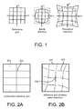
- Figure 1 schematically shows image distortion.
- a reference grid in the form of 5 horizontal and 5 vertical lines, is imaged by two systems, one system showing barrel distortion (A 21 ⁇ 0) and one system showing pincushion distortion (A 21 > 0). Barrel- and pincushion distortion are the most well-known distortions.
- Figure 2 shows the effect of anisotropic distortion, also known as spiral distortion.
- FIG 2 the effect of spiral distortion is shown.
- Spiral distortion is a distortion peculiar to magnetic lenses. Magnetic lenses are often used in electron-optical apparatus.
- the effect of spiral distortion is that an image point at a distance from the particle-optical axis is rotated to an amount proportional to the distance to said axis.
- Figure 2A shows an undistorted reference grid 202 within a field-of-view 201
- figure 2B the reference grid imaged with spiral distortion, resulting in a distorted grid 203 within a field-of-view 201. It is noted that spiral distortion equals zero round the particle-optical axis or rotation centre 204.
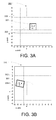
- Figure 3A schematically shows an image 300 centred round optical axis 301 and defined by a field of view 302. Within the image a sub-image 303 is identified, that in this image is centred round the particle-optical axis 301.
- Figure 3B shows another image 310, in which the object is slightly shifted. Due to distortions the sub-image 304-1 is slightly warped, which in first approximation can be described by a rotation and a change in magnification in the x and y direction when compared to the original sub-image shown in figure 3A . It is noted that the shift can be determined in several ways, including correlation of the whole image, identifying the sub-image, or by other means that may include read-out of the object carrier by e.g. an optical interferometer, capacitative measurements, etc.
- the distortions anywhere in the field-of-view can be determined. It is noted that the distortions will often show symmetry round the particle-optical axis, so that the parameter for missing locations can be derived from the parameters of other points.
- the distortion for a specific point can now be determined by integrating the distortions for each of the points between the axis and the specific point, taking into account e.g. the curving of the path due to spiral distortion.
- Figure 4 schematically shows a flowchart for determining the sub-image distortions.
- first step 401 a first image is acquired.
- step 402 the intersection of the particle-optical axis and the image plane is determined, e.g. by changing the excitation of the projection system, also known as "wobbling" of the projection system.
- a sub-image surrounding the centre is defined.
- This sub-image must contain some well defined structures. Further the sub-image must be sufficiently large to detect a small rotation of the sub-image due to distortions, but sufficiently small to be distortion free over the size of the sub-image. Inventors found that for a modern TEM with a 4000x4000 pixel camera system a sub-image size of between 64x64 and 512x512 pixels, gave good results.
- step 404 the object is shifted.
- the accuracy of the shift function of the object holder is such that it is ascertained that the sub-image is kept within the field-of-view.
- step 405 an image is acquired.
- step 406 the shift of the image with respect to the first image is determined.
- this can be done by correlation of the images, either with the full number of pixels available or with a reduced number of pixels, or it can be determined by looking for the sub-image and determining the shift between the sub-image and the centre of the first image. Also other means can be envisioned, such as with the aid of optical interferometry, etc.
- step 407 with a known shift from centre to new position, the sub-image is identified.
- step 408 the distortions of the sub-image are determined. It is noted that a first approximation of ⁇ Mx, ⁇ My and ⁇ is often sufficient to describe the distortions. Inventors found that it was sufficient to determine ⁇ M and ⁇ , although it might be that for some systems both ⁇ Mx and ⁇ My should be determined separately.
- step 409 it is determined whether sufficient points are gathered. This depends on the number, but also on the spread of the points over the field-of-view. If there are not enough points yet, a next shift is made in a subsequent step 404.
- the image shows an object with high contrast and high detail.
- a biological object stained with a heavy metal such as osmium or tungsten.
- gold particles e.g. in the form colloidal particles or in the form of organometallic particles, comprising e.g. gold and a protein, in conjunction with a biological sample results in such a high contrast, high detail image.
- a method of reconstructing the distortion in the image from the measured sub-image distortions is as follows:
- the distortion can be derived by going to the centre (the place where the particle-optical axis intersects the image plane) whilst integrating the distortions of the sub-fields in the path.
- this is the addition of the distortions when going from the distorted point to the centre, so: from a starting point make a step with length ds in the direction ⁇ of the centre, corrected for the sub-field distortions ⁇ M and ⁇ (so resulting in step size ds (1- ⁇ M) and in direction ⁇ - ⁇ ).
- This corresponds in the corrected world with a step ds in direction ⁇ . From this new position this is repeated until the centre is reached.
- the distorted pixel should be imaged. In this way the displayed location of a detected point can be changed so as to cancel the distortion in the detected image, and an image can be build that is free of distortion or at least shows much reduced distortion.
- the above method works well when the centres of the sub-fields form a relatively dense grid in the field of view.
- the distortion values can be derived by interpolating the values of the scaling ⁇ M and rotation ⁇ from nearby points, e.g. by Delaunay triangulation.
- the distortions of the sub-fields are expressed as polynomials or spleen function
- the distortion for each position can be estimated by direct integration of said functions.
- interpolation of distortion values may also take the form of interpolation between distortion values for different settings of the projection system.
Landscapes
- Chemical & Material Sciences (AREA)
- Analytical Chemistry (AREA)
- Engineering & Computer Science (AREA)
- Physics & Mathematics (AREA)
- General Physics & Mathematics (AREA)
- Theoretical Computer Science (AREA)
- Computer Vision & Pattern Recognition (AREA)
- Image Processing (AREA)
- Analysing Materials By The Use Of Radiation (AREA)
- Geometry (AREA)
- Testing Of Optical Devices Or Fibers (AREA)
Priority Applications (6)
| Application Number | Priority Date | Filing Date | Title |
|---|---|---|---|
| EP08171413A EP2197018A1 (fr) | 2008-12-12 | 2008-12-12 | Procédé pour déterminer les distorsions dans un appareil optique corpusculaire |
| JP2009278580A JP5558088B2 (ja) | 2008-12-12 | 2009-12-08 | 粒子光学装置の歪曲を特定するための方法 |
| CN200910260522.4A CN101858821B (zh) | 2008-12-12 | 2009-12-11 | 用于确定粒子-光学仪器中畸变的方法 |
| US12/636,592 US8447133B2 (en) | 2008-12-12 | 2009-12-11 | Method for determining distortions in a particle-optical apparatus |
| EP09178788A EP2197017A3 (fr) | 2008-12-12 | 2009-12-11 | Procédé pour déterminer les distorsions dans un appareil optique corpusculaire |
| US13/799,223 US8885973B2 (en) | 2008-12-12 | 2013-03-13 | Method for determining distortions in a particle-optical apparatus |
Applications Claiming Priority (1)
| Application Number | Priority Date | Filing Date | Title |
|---|---|---|---|
| EP08171413A EP2197018A1 (fr) | 2008-12-12 | 2008-12-12 | Procédé pour déterminer les distorsions dans un appareil optique corpusculaire |
Publications (1)
| Publication Number | Publication Date |
|---|---|
| EP2197018A1 true EP2197018A1 (fr) | 2010-06-16 |
Family
ID=40564943
Family Applications (2)
| Application Number | Title | Priority Date | Filing Date |
|---|---|---|---|
| EP08171413A Withdrawn EP2197018A1 (fr) | 2008-12-12 | 2008-12-12 | Procédé pour déterminer les distorsions dans un appareil optique corpusculaire |
| EP09178788A Withdrawn EP2197017A3 (fr) | 2008-12-12 | 2009-12-11 | Procédé pour déterminer les distorsions dans un appareil optique corpusculaire |
Family Applications After (1)
| Application Number | Title | Priority Date | Filing Date |
|---|---|---|---|
| EP09178788A Withdrawn EP2197017A3 (fr) | 2008-12-12 | 2009-12-11 | Procédé pour déterminer les distorsions dans un appareil optique corpusculaire |
Country Status (4)
| Country | Link |
|---|---|
| US (2) | US8447133B2 (fr) |
| EP (2) | EP2197018A1 (fr) |
| JP (1) | JP5558088B2 (fr) |
| CN (1) | CN101858821B (fr) |
Cited By (5)
| Publication number | Priority date | Publication date | Assignee | Title |
|---|---|---|---|---|
| CN105744243A (zh) * | 2016-01-21 | 2016-07-06 | 上海应用技术学院 | 基于切交点特征实现的多投影拼接中全自动几何校正方法 |
| GB2555643A (en) * | 2016-11-08 | 2018-05-09 | Nokia Technologies Oy | Determining an intersection location of an optical axis of a lens with a camera sensor |
| CN108022217A (zh) * | 2017-11-26 | 2018-05-11 | 合肥赛为智能有限公司 | 一种空中拍摄形变调整方法 |
| WO2020070156A1 (fr) * | 2018-10-02 | 2020-04-09 | Carl Zeiss Smt Gmbh | Procédé d'enregistrement d'une image à l'aide d'un microscope à particules |
| EP4009042A1 (fr) * | 2015-03-23 | 2022-06-08 | Techinsights Inc. | Procédés, systèmes et dispositifs se rapportant à une correction de la distorsion dans des dispositifs d'imagerie |
Families Citing this family (72)
| Publication number | Priority date | Publication date | Assignee | Title |
|---|---|---|---|---|
| GB0718706D0 (en) | 2007-09-25 | 2007-11-07 | Creative Physics Ltd | Method and apparatus for reducing laser speckle |
| EP2197018A1 (fr) | 2008-12-12 | 2010-06-16 | FEI Company | Procédé pour déterminer les distorsions dans un appareil optique corpusculaire |
| US9335604B2 (en) | 2013-12-11 | 2016-05-10 | Milan Momcilo Popovich | Holographic waveguide display |
| US11726332B2 (en) | 2009-04-27 | 2023-08-15 | Digilens Inc. | Diffractive projection apparatus |
| US11300795B1 (en) | 2009-09-30 | 2022-04-12 | Digilens Inc. | Systems for and methods of using fold gratings coordinated with output couplers for dual axis expansion |
| US11320571B2 (en) | 2012-11-16 | 2022-05-03 | Rockwell Collins, Inc. | Transparent waveguide display providing upper and lower fields of view with uniform light extraction |
| US8233204B1 (en) | 2009-09-30 | 2012-07-31 | Rockwell Collins, Inc. | Optical displays |
| US10795160B1 (en) | 2014-09-25 | 2020-10-06 | Rockwell Collins, Inc. | Systems for and methods of using fold gratings for dual axis expansion |
| US9341846B2 (en) | 2012-04-25 | 2016-05-17 | Rockwell Collins Inc. | Holographic wide angle display |
| US8659826B1 (en) | 2010-02-04 | 2014-02-25 | Rockwell Collins, Inc. | Worn display system and method without requiring real time tracking for boresight precision |
| WO2012136970A1 (fr) | 2011-04-07 | 2012-10-11 | Milan Momcilo Popovich | Dispositif d'élimination de la granularité laser basé sur une diversité angulaire |
| WO2016020630A2 (fr) | 2014-08-08 | 2016-02-11 | Milan Momcilo Popovich | Illuminateur laser en guide d'ondes comprenant un dispositif de déchatoiement |
| US20140204455A1 (en) | 2011-08-24 | 2014-07-24 | Milan Momcilo Popovich | Wearable data display |
| US10670876B2 (en) | 2011-08-24 | 2020-06-02 | Digilens Inc. | Waveguide laser illuminator incorporating a despeckler |
| US9366864B1 (en) | 2011-09-30 | 2016-06-14 | Rockwell Collins, Inc. | System for and method of displaying information without need for a combiner alignment detector |
| US8634139B1 (en) | 2011-09-30 | 2014-01-21 | Rockwell Collins, Inc. | System for and method of catadioptric collimation in a compact head up display (HUD) |
| US8749890B1 (en) | 2011-09-30 | 2014-06-10 | Rockwell Collins, Inc. | Compact head up display (HUD) for cockpits with constrained space envelopes |
| US9715067B1 (en) | 2011-09-30 | 2017-07-25 | Rockwell Collins, Inc. | Ultra-compact HUD utilizing waveguide pupil expander with surface relief gratings in high refractive index materials |
| US9599813B1 (en) | 2011-09-30 | 2017-03-21 | Rockwell Collins, Inc. | Waveguide combiner system and method with less susceptibility to glare |
| US8937772B1 (en) | 2011-09-30 | 2015-01-20 | Rockwell Collins, Inc. | System for and method of stowing HUD combiners |
| US8903207B1 (en) | 2011-09-30 | 2014-12-02 | Rockwell Collins, Inc. | System for and method of extending vertical field of view in head up display utilizing a waveguide combiner |
| EP2584584A1 (fr) | 2011-10-19 | 2013-04-24 | FEI Company | Procédé d'ajustement d'un METB équipé d'un correcteur d'aberrations |
| WO2013102759A2 (fr) | 2012-01-06 | 2013-07-11 | Milan Momcilo Popovich | Capteur d'image à contact utilisant des réseaux de bragg commutables |
| JP6116598B2 (ja) * | 2012-03-08 | 2017-04-19 | アップファイブ エルエルシー | 物質中のひずみを高空間分解能で測定するためのシステムおよび方法 |
| US8830588B1 (en) | 2012-03-28 | 2014-09-09 | Rockwell Collins, Inc. | Reflector and cover glass for substrate guided HUD |
| US9523852B1 (en) | 2012-03-28 | 2016-12-20 | Rockwell Collins, Inc. | Micro collimator system and method for a head up display (HUD) |
| EP2704177B1 (fr) | 2012-09-04 | 2014-11-26 | Fei Company | Procédé d'investigation et de correction des aberrations dans un système de lentilles à particules chargées |
| US9933684B2 (en) | 2012-11-16 | 2018-04-03 | Rockwell Collins, Inc. | Transparent waveguide display providing upper and lower fields of view having a specific light output aperture configuration |
| DE102013101445B9 (de) * | 2013-02-14 | 2022-01-05 | Carl Zeiss Smt Gmbh | Verfahren zur Ermittlung von Verzeichnungseigenschaften eines optischen Systems in einer Messvorrichtung für die Mikrolithographie |
| US9674413B1 (en) | 2013-04-17 | 2017-06-06 | Rockwell Collins, Inc. | Vision system and method having improved performance and solar mitigation |
| US9727772B2 (en) | 2013-07-31 | 2017-08-08 | Digilens, Inc. | Method and apparatus for contact image sensing |
| US9244281B1 (en) | 2013-09-26 | 2016-01-26 | Rockwell Collins, Inc. | Display system and method using a detached combiner |
| US10732407B1 (en) | 2014-01-10 | 2020-08-04 | Rockwell Collins, Inc. | Near eye head up display system and method with fixed combiner |
| US20190287759A1 (en) * | 2014-01-27 | 2019-09-19 | Mochii, Inc. (D/B/A Voxa) | Transmission Electron Microscopy |
| US9519089B1 (en) | 2014-01-30 | 2016-12-13 | Rockwell Collins, Inc. | High performance volume phase gratings |
| US9244280B1 (en) | 2014-03-25 | 2016-01-26 | Rockwell Collins, Inc. | Near eye display system and method for display enhancement or redundancy |
| EP2966668B1 (fr) | 2014-07-10 | 2016-10-12 | Fei Company | Procédé d'étalonnage d'un microscope à particules chargées de transmission de balayage |
| US10359736B2 (en) | 2014-08-08 | 2019-07-23 | Digilens Inc. | Method for holographic mastering and replication |
| US10241330B2 (en) | 2014-09-19 | 2019-03-26 | Digilens, Inc. | Method and apparatus for generating input images for holographic waveguide displays |
| US10088675B1 (en) | 2015-05-18 | 2018-10-02 | Rockwell Collins, Inc. | Turning light pipe for a pupil expansion system and method |
| US9715110B1 (en) | 2014-09-25 | 2017-07-25 | Rockwell Collins, Inc. | Automotive head up display (HUD) |
| CN107873086B (zh) | 2015-01-12 | 2020-03-20 | 迪吉伦斯公司 | 环境隔离的波导显示器 |
| US9632226B2 (en) | 2015-02-12 | 2017-04-25 | Digilens Inc. | Waveguide grating device |
| US10126552B2 (en) | 2015-05-18 | 2018-11-13 | Rockwell Collins, Inc. | Micro collimator system and method for a head up display (HUD) |
| US11366316B2 (en) | 2015-05-18 | 2022-06-21 | Rockwell Collins, Inc. | Head up display (HUD) using a light pipe |
| US10247943B1 (en) | 2015-05-18 | 2019-04-02 | Rockwell Collins, Inc. | Head up display (HUD) using a light pipe |
| US10108010B2 (en) | 2015-06-29 | 2018-10-23 | Rockwell Collins, Inc. | System for and method of integrating head up displays and head down displays |
| EP3121637B1 (fr) * | 2015-07-24 | 2021-09-01 | Leica Instruments (Singapore) Pte. Ltd. | Microscope et procêdê de gênêration d'une image combinêe à partir de plusieurs images individuelles d'un objet |
| KR101714213B1 (ko) * | 2015-09-09 | 2017-03-09 | 현대오트론 주식회사 | 렌즈 영상 왜곡 보정 장치 |
| WO2017060665A1 (fr) | 2015-10-05 | 2017-04-13 | Milan Momcilo Popovich | Afficheur à guide d'ondes |
| US10598932B1 (en) | 2016-01-06 | 2020-03-24 | Rockwell Collins, Inc. | Head up display for integrating views of conformally mapped symbols and a fixed image source |
| WO2017162999A1 (fr) | 2016-03-24 | 2017-09-28 | Popovich Milan Momcilo | Procédé et appareil pour fournir un dispositif guide d'ondes holographique sélectif en polarisation |
| JP6734933B2 (ja) | 2016-04-11 | 2020-08-05 | ディジレンズ インコーポレイテッド | 構造化光投影のためのホログラフィック導波管装置 |
| CN106093108B (zh) * | 2016-05-19 | 2018-10-16 | 南京航空航天大学 | 基于间隙缺陷识别的单向纤维增韧复合材料等效导热系数预估方法 |
| CN106500969B (zh) * | 2016-11-17 | 2019-07-26 | 深圳Tcl新技术有限公司 | 显示屏均匀性测试方法及显示屏均匀性测试系统 |
| WO2018102834A2 (fr) | 2016-12-02 | 2018-06-07 | Digilens, Inc. | Dispositif de guide d'ondes à éclairage de sortie uniforme |
| WO2018129398A1 (fr) | 2017-01-05 | 2018-07-12 | Digilens, Inc. | Dispositifs d'affichage tête haute vestimentaires |
| US10295824B2 (en) | 2017-01-26 | 2019-05-21 | Rockwell Collins, Inc. | Head up display with an angled light pipe |
| DE102017212214A1 (de) * | 2017-07-17 | 2019-01-17 | Carl Zeiss Microscopy Gmbh | Verfahren zum Aufzeichnen eines Bildes unter Verwendung eines Teilchenmikroskops und Teilchenmikroskop |
| WO2019049260A1 (fr) * | 2017-09-07 | 2019-03-14 | 株式会社日立ハイテクノロジーズ | Dispositif de traitement d'image |
| JP7399084B2 (ja) | 2017-10-16 | 2023-12-15 | ディジレンズ インコーポレイテッド | ピクセル化されたディスプレイの画像分解能を倍増させるためのシステムおよび方法 |
| US20190212588A1 (en) | 2018-01-08 | 2019-07-11 | Digilens, Inc. | Systems and Methods for Manufacturing Waveguide Cells |
| JP7404243B2 (ja) | 2018-01-08 | 2023-12-25 | ディジレンズ インコーポレイテッド | 導波管セル内のホログラフィック格子の高スループット記録のためのシステムおよび方法 |
| WO2019136476A1 (fr) | 2018-01-08 | 2019-07-11 | Digilens, Inc. | Architectures de guides d'ondes et procédés de fabrication associés |
| US11402801B2 (en) | 2018-07-25 | 2022-08-02 | Digilens Inc. | Systems and methods for fabricating a multilayer optical structure |
| EP3924759A4 (fr) | 2019-02-15 | 2022-12-28 | Digilens Inc. | Procédés et appareils pour fournir un affichage de guide d'ondes holographique à l'aide de réseaux intégrés |
| JP2022525165A (ja) | 2019-03-12 | 2022-05-11 | ディジレンズ インコーポレイテッド | ホログラフィック導波管バックライトおよび関連する製造方法 |
| DE102020108514A1 (de) * | 2019-03-28 | 2020-10-01 | Carl Zeiss Microscopy Gmbh | Verfahren zum Bestimmen eines Bildaufnahmefehlers |
| US20200386947A1 (en) | 2019-06-07 | 2020-12-10 | Digilens Inc. | Waveguides Incorporating Transmissive and Reflective Gratings and Related Methods of Manufacturing |
| EP4004646A4 (fr) | 2019-07-29 | 2023-09-06 | Digilens Inc. | Procédés et appareils de multiplication de la résolution d'image et du champ de vision d'un écran d'affichage pixélisé |
| US12073541B2 (en) | 2019-08-09 | 2024-08-27 | The Board Of Regents Of The University Of Texas System | Methods for high-performance electron microscopy |
| KR20220054386A (ko) | 2019-08-29 | 2022-05-02 | 디지렌즈 인코포레이티드. | 진공 브래그 격자 및 이의 제조 방법 |
Family Cites Families (25)
| Publication number | Priority date | Publication date | Assignee | Title |
|---|---|---|---|---|
| NL9100294A (nl) | 1991-02-20 | 1992-09-16 | Philips Nv | Geladen deeltjesbundelinrichting. |
| DE69402283T2 (de) | 1993-05-21 | 1997-09-18 | Philips Electronics Nv | Energiefilter mit Korrektur von chromatischen Aberrationen zweiter ordnung |
| EP0644411B1 (fr) | 1993-09-17 | 1997-03-26 | ESSILOR INTERNATIONAL (Compagnie Générale d'Optique) | Procédé de mesure absolue de la structure géométrique ou optique d'un composant optique et dispositif pour sa mise en oeuvre |
| WO1997044811A1 (fr) * | 1996-05-21 | 1997-11-27 | Philips Electronics N.V. | Correcteur d'aberrations de lentilles d'appareils optiques a rayonnement corpusculaire |
| US5627373A (en) * | 1996-06-17 | 1997-05-06 | Hewlett-Packard Company | Automatic electron beam alignment and astigmatism correction in scanning electron microscope |
| EP0868739B1 (fr) * | 1996-09-20 | 2005-06-01 | Fei Company | Dispositif correcteur pour corriger les aberrations chromatiques dans un appareil optique a particules |
| JP2001509952A (ja) * | 1997-11-20 | 2001-07-24 | フィリップス エレクトロン オプティクス ビー ヴィ | 粒子光学的装置の色収差を補正するための装置 |
| WO1999030342A1 (fr) * | 1997-12-11 | 1999-06-17 | Philips Electron Optics B.V. | Dispositif de correction de l'aberration spherique dans un appareil optique a particules |
| WO1999033085A1 (fr) * | 1997-12-22 | 1999-07-01 | Philips Electron Optics B.V. | Dispositif de correction des aberrations chromatiques dans des appareils d'optique particulaire |
| JP2001274973A (ja) * | 2000-03-24 | 2001-10-05 | Sanyo Electric Co Ltd | 顕微鏡画像合成装置、顕微鏡画像合成方法、顕微鏡画像合成処理プログラムを記録したコンピュータ読み取り可能な記録媒体 |
| US6552340B1 (en) | 2000-10-12 | 2003-04-22 | Nion Co. | Autoadjusting charged-particle probe-forming apparatus |
| JP3986260B2 (ja) * | 2001-01-19 | 2007-10-03 | 株式会社東芝 | 欠陥検査装置及びそれを用いたデバイス製造方法 |
| CN100341106C (zh) | 2001-10-10 | 2007-10-03 | 应用材料以色列有限公司 | 对准带电颗粒束列的方法与装置 |
| JP3968421B2 (ja) * | 2002-07-01 | 2007-08-29 | 独立行政法人産業技術総合研究所 | 電子顕微鏡観察像の画像処理方法および画像処理プログラム並びに記録媒体 |
| EP1717840B1 (fr) * | 2005-04-05 | 2011-06-08 | Fei Company | Dispositif à particules chargées avec correcteur d'aberrations |
| NL1029847C2 (nl) | 2005-09-01 | 2007-03-05 | Fei Co | Werkwijze voor het bepalen van lensfouten in een deeltjes-optisch apparaat. |
| EP1783811A3 (fr) | 2005-11-02 | 2008-02-27 | FEI Company | Correcteur pour la correction d'aberrations chromatiques dans un appareil optique à particules |
| JP4790567B2 (ja) | 2005-11-30 | 2011-10-12 | 日本電子株式会社 | ロンチグラムを用いた収差測定方法及び収差補正方法及び電子顕微鏡 |
| EP1796130A1 (fr) * | 2005-12-06 | 2007-06-13 | FEI Company | Procédé de determination des coefficients de la fonction d'aberration d'une lentille à particules chargées |
| JP4801518B2 (ja) * | 2006-07-07 | 2011-10-26 | 株式会社日立ハイテクノロジーズ | 荷電粒子線顕微方法および荷電粒子線装置 |
| JP5134804B2 (ja) * | 2006-10-06 | 2013-01-30 | 株式会社日立ハイテクノロジーズ | 走査電子顕微鏡および走査電子顕微鏡像の歪み校正 |
| JP4891788B2 (ja) * | 2007-01-15 | 2012-03-07 | 日本電子株式会社 | 電子顕微鏡像の歪み補正方法及び輝度補正方法 |
| JP5223208B2 (ja) * | 2007-03-01 | 2013-06-26 | 株式会社日立製作所 | 透過型電子顕微鏡 |
| JP5129509B2 (ja) * | 2007-05-14 | 2013-01-30 | 株式会社日立ハイテクノロジーズ | 透過型電子顕微鏡及び撮影方法 |
| EP2197018A1 (fr) | 2008-12-12 | 2010-06-16 | FEI Company | Procédé pour déterminer les distorsions dans un appareil optique corpusculaire |
-
2008
- 2008-12-12 EP EP08171413A patent/EP2197018A1/fr not_active Withdrawn
-
2009
- 2009-12-08 JP JP2009278580A patent/JP5558088B2/ja active Active
- 2009-12-11 US US12/636,592 patent/US8447133B2/en active Active
- 2009-12-11 EP EP09178788A patent/EP2197017A3/fr not_active Withdrawn
- 2009-12-11 CN CN200910260522.4A patent/CN101858821B/zh active Active
-
2013
- 2013-03-13 US US13/799,223 patent/US8885973B2/en active Active
Non-Patent Citations (5)
| Title |
|---|
| DATABASE INSPEC [online] THE INSTITUTION OF ELECTRICAL ENGINEERS, STEVENAGE, GB; Database accession no. 1963B10390 * |
| DAVID G LOWE: "Distinctive Image Features from Scale-Invariant Keypoints", INTERNATIONAL JOURNAL OF COMPUTER VISION, KLUWER ACADEMIC PUBLISHERS, BO, vol. 60, no. 2, 1 November 2004 (2004-11-01), pages 91 - 110, XP019216426, ISSN: 1573-1405 * |
| F. HUE ET AL.: "Calibration of projector lens distortions for quantitative high-resolution TEM", MICROSC. MICROANAL., vol. 11, no. 2, 2005, pages 552 - 553, XP009116864 |
| HECKMAN F A ET AL: "The reduction of error in magnification determination in electron microscopes", ELECTRON MICROSCOPY. FIFTH INTERNATIONAL CONGRESS 29 AUG. 1962 - 5 SEPT. 1962 PHILADELPHIA, PA, USA, vol. 1, 1962, Electron Microscopy Conference, XP009116862 * |
| KAYNIG V ET AL: "Probabilistic image registration and anomaly detection by nonlinear warping", COMPUTER VISION AND PATTERN RECOGNITION, 2008. CVPR 2008. IEEE CONFERENCE ON, IEEE, PISCATAWAY, NJ, USA, 23 June 2008 (2008-06-23), pages 1 - 8, XP031297301, ISBN: 978-1-4244-2242-5 * |
Cited By (10)
| Publication number | Priority date | Publication date | Assignee | Title |
|---|---|---|---|---|
| EP4009042A1 (fr) * | 2015-03-23 | 2022-06-08 | Techinsights Inc. | Procédés, systèmes et dispositifs se rapportant à une correction de la distorsion dans des dispositifs d'imagerie |
| CN105744243A (zh) * | 2016-01-21 | 2016-07-06 | 上海应用技术学院 | 基于切交点特征实现的多投影拼接中全自动几何校正方法 |
| CN105744243B (zh) * | 2016-01-21 | 2017-08-29 | 上海应用技术学院 | 基于切交点特征实现的多投影拼接中全自动几何校正方法 |
| GB2555643A (en) * | 2016-11-08 | 2018-05-09 | Nokia Technologies Oy | Determining an intersection location of an optical axis of a lens with a camera sensor |
| CN108022217A (zh) * | 2017-11-26 | 2018-05-11 | 合肥赛为智能有限公司 | 一种空中拍摄形变调整方法 |
| CN108022217B (zh) * | 2017-11-26 | 2021-07-30 | 合肥赛为智能有限公司 | 一种空中拍摄形变调整方法 |
| WO2020070156A1 (fr) * | 2018-10-02 | 2020-04-09 | Carl Zeiss Smt Gmbh | Procédé d'enregistrement d'une image à l'aide d'un microscope à particules |
| CN112805747A (zh) * | 2018-10-02 | 2021-05-14 | 卡尔蔡司Smt有限责任公司 | 使用粒子显微镜来记录图像的方法 |
| KR20210069690A (ko) * | 2018-10-02 | 2021-06-11 | 칼 짜이스 에스엠테 게엠베하 | 입자 현미경을 사용하여 영상을 기록하는 방법 |
| US11728130B2 (en) | 2018-10-02 | 2023-08-15 | Carl Zeiss Smt Gmbh | Method of recording an image using a particle microscope |
Also Published As
| Publication number | Publication date |
|---|---|
| US8447133B2 (en) | 2013-05-21 |
| JP2010140899A (ja) | 2010-06-24 |
| EP2197017A2 (fr) | 2010-06-16 |
| EP2197017A3 (fr) | 2011-01-26 |
| US20100246993A1 (en) | 2010-09-30 |
| US8885973B2 (en) | 2014-11-11 |
| US20130266240A1 (en) | 2013-10-10 |
| CN101858821A (zh) | 2010-10-13 |
| JP5558088B2 (ja) | 2014-07-23 |
| CN101858821B (zh) | 2014-03-26 |
Similar Documents
| Publication | Publication Date | Title |
|---|---|---|
| US8885973B2 (en) | Method for determining distortions in a particle-optical apparatus | |
| US20200126201A1 (en) | Sample observation device and sample observation method | |
| US8692196B2 (en) | Method of use for a multipole detector for a transmission electron microscope | |
| EP1804272B1 (fr) | Procédé de détermination des coefficients d'aberration de la fonction d'aberration d'une lentille optique à particules | |
| JP5422673B2 (ja) | 荷電粒子線顕微鏡及びそれを用いた測定方法 | |
| JP5603421B2 (ja) | 自動収差補正法を備えた荷電粒子線装置 | |
| JP2010062106A (ja) | 走査型荷電粒子顕微鏡装置及び走査型荷電粒子顕微鏡装置で取得した画像の処理方法 | |
| WO2015015985A1 (fr) | Dispositif à faisceau de particules chargées et procédé de mesure d'aberration dans un dispositif à faisceau de particules chargées | |
| KR102149947B1 (ko) | 투과 전자 현미경 샘플 정렬 시스템 및 방법 | |
| JP7232326B2 (ja) | 粒子顕微鏡を用いる画像記録方法 | |
| US20070206847A1 (en) | Correction of vibration-induced and random positioning errors in tomosynthesis | |
| US11545337B2 (en) | Scanning transmission electron microscope and adjustment method of optical system | |
| US11011346B2 (en) | Electron beam device and image processing method | |
| Printemps et al. | Non‐rigid alignment in electron tomography in materials science | |
| JP4409861B2 (ja) | 三次元座標測定装置及び方法 | |
| JP2003317654A (ja) | 電子顕微方法及びそれを用いた電子顕微鏡並び生体試料検査方法及び生体検査装置 | |
| EP3637452A1 (fr) | Microscope à particules chargées et procédé de réglage d'un microscope à particules chargées | |
| Postek et al. | Nanomanufacturing concerns about measurements made in the SEM Part V: dealing with noise | |
| Tivol | Automated Functions in Electron Microscopy | |
| JP2006294443A (ja) | 走査像観察機能を有した透過電子顕微鏡 |
Legal Events
| Date | Code | Title | Description |
|---|---|---|---|
| PUAI | Public reference made under article 153(3) epc to a published international application that has entered the european phase |
Free format text: ORIGINAL CODE: 0009012 |
|
| AK | Designated contracting states |
Kind code of ref document: A1 Designated state(s): AT BE BG CH CY CZ DE DK EE ES FI FR GB GR HR HU IE IS IT LI LT LU LV MC MT NL NO PL PT RO SE SI SK TR |
|
| AX | Request for extension of the european patent |
Extension state: AL BA MK RS |
|
| AKY | No designation fees paid | ||
| REG | Reference to a national code |
Ref country code: DE Ref legal event code: 8566 |
|
| STAA | Information on the status of an ep patent application or granted ep patent |
Free format text: STATUS: THE APPLICATION IS DEEMED TO BE WITHDRAWN |
|
| 18D | Application deemed to be withdrawn |
Effective date: 20101217 |