EP2184113A1 - Auspressvorrichtung - Google Patents
Auspressvorrichtung Download PDFInfo
- Publication number
- EP2184113A1 EP2184113A1 EP09172496A EP09172496A EP2184113A1 EP 2184113 A1 EP2184113 A1 EP 2184113A1 EP 09172496 A EP09172496 A EP 09172496A EP 09172496 A EP09172496 A EP 09172496A EP 2184113 A1 EP2184113 A1 EP 2184113A1
- Authority
- EP
- European Patent Office
- Prior art keywords
- piston rod
- drive means
- squeezing device
- holes
- gear
- Prior art date
- Legal status (The legal status is an assumption and is not a legal conclusion. Google has not performed a legal analysis and makes no representation as to the accuracy of the status listed.)
- Granted
Links
Images
Classifications
-
- B—PERFORMING OPERATIONS; TRANSPORTING
- B05—SPRAYING OR ATOMISING IN GENERAL; APPLYING FLUENT MATERIALS TO SURFACES, IN GENERAL
- B05C—APPARATUS FOR APPLYING FLUENT MATERIALS TO SURFACES, IN GENERAL
- B05C17/00—Hand tools or apparatus using hand held tools, for applying liquids or other fluent materials to, for spreading applied liquids or other fluent materials on, or for partially removing applied liquids or other fluent materials from, surfaces
- B05C17/005—Hand tools or apparatus using hand held tools, for applying liquids or other fluent materials to, for spreading applied liquids or other fluent materials on, or for partially removing applied liquids or other fluent materials from, surfaces for discharging material from a reservoir or container located in or on the hand tool through an outlet orifice by pressure without using surface contacting members like pads or brushes
- B05C17/01—Hand tools or apparatus using hand held tools, for applying liquids or other fluent materials to, for spreading applied liquids or other fluent materials on, or for partially removing applied liquids or other fluent materials from, surfaces for discharging material from a reservoir or container located in or on the hand tool through an outlet orifice by pressure without using surface contacting members like pads or brushes with manually mechanically or electrically actuated piston or the like
- B05C17/0103—Hand tools or apparatus using hand held tools, for applying liquids or other fluent materials to, for spreading applied liquids or other fluent materials on, or for partially removing applied liquids or other fluent materials from, surfaces for discharging material from a reservoir or container located in or on the hand tool through an outlet orifice by pressure without using surface contacting members like pads or brushes with manually mechanically or electrically actuated piston or the like with electrically actuated piston or the like
-
- B—PERFORMING OPERATIONS; TRANSPORTING
- B05—SPRAYING OR ATOMISING IN GENERAL; APPLYING FLUENT MATERIALS TO SURFACES, IN GENERAL
- B05C—APPARATUS FOR APPLYING FLUENT MATERIALS TO SURFACES, IN GENERAL
- B05C17/00—Hand tools or apparatus using hand held tools, for applying liquids or other fluent materials to, for spreading applied liquids or other fluent materials on, or for partially removing applied liquids or other fluent materials from, surfaces
- B05C17/005—Hand tools or apparatus using hand held tools, for applying liquids or other fluent materials to, for spreading applied liquids or other fluent materials on, or for partially removing applied liquids or other fluent materials from, surfaces for discharging material from a reservoir or container located in or on the hand tool through an outlet orifice by pressure without using surface contacting members like pads or brushes
- B05C17/00576—Hand tools or apparatus using hand held tools, for applying liquids or other fluent materials to, for spreading applied liquids or other fluent materials on, or for partially removing applied liquids or other fluent materials from, surfaces for discharging material from a reservoir or container located in or on the hand tool through an outlet orifice by pressure without using surface contacting members like pads or brushes characterised by the construction of a piston as pressure exerting means, or of the co-operating container
-
- B—PERFORMING OPERATIONS; TRANSPORTING
- B65—CONVEYING; PACKING; STORING; HANDLING THIN OR FILAMENTARY MATERIAL
- B65D—CONTAINERS FOR STORAGE OR TRANSPORT OF ARTICLES OR MATERIALS, e.g. BAGS, BARRELS, BOTTLES, BOXES, CANS, CARTONS, CRATES, DRUMS, JARS, TANKS, HOPPERS, FORWARDING CONTAINERS; ACCESSORIES, CLOSURES, OR FITTINGS THEREFOR; PACKAGING ELEMENTS; PACKAGES
- B65D83/00—Containers or packages with special means for dispensing contents
- B65D83/76—Containers or packages with special means for dispensing contents for dispensing fluent contents by means of a piston
- B65D83/768—Containers or packages with special means for dispensing contents for dispensing fluent contents by means of a piston the piston or movable bottom being pulled upwards to dispense the contents
-
- F—MECHANICAL ENGINEERING; LIGHTING; HEATING; WEAPONS; BLASTING
- F16—ENGINEERING ELEMENTS AND UNITS; GENERAL MEASURES FOR PRODUCING AND MAINTAINING EFFECTIVE FUNCTIONING OF MACHINES OR INSTALLATIONS; THERMAL INSULATION IN GENERAL
- F16N—LUBRICATING
- F16N3/00—Devices for supplying lubricant by manual action
- F16N3/10—Devices for supplying lubricant by manual action delivering grease
- F16N3/12—Grease guns
Definitions
- the invention relates to a squeezing device for mass-containing container with at least one piston rod, which has a profiling along its longitudinal extension, and with a drive unit for the at least one piston rod with a meshing with the profiling of the at least one piston rod drive means.
- Such a squeezing device serves to dispense in containers, such. B. in foil pouches or cartridges, packed masses at an application site.
- This squeezing device is for discharging different types of masses, such. As mortar or sealants suitable.
- the drive means is activated and the at least one piston rod is advanced over a predetermined amount, wherein a pressure plate arranged on the piston rod acts on the container and a corresponding quantity of the mass present therein is applied through an outlet opening of the extrusion device.
- the piston rod To replace a squeezed out container, the piston rod must be retracted so that the container inserted into the squeezing device can be removed from it and replaced by another container.
- a squeezing device with a piston rod, which has a tooth profile along its longitudinal extent, and with a drive unit for the at least one piston rod known.
- the drive unit comprises a motor and a gear drive and a driven by the drive, with the tooth profiling of the at least one piston rod meshing gear as drive means.
- the previously advanced by the drive unit piston rod is moved back to its original position in which the inserted container can be removed and a new container in the squeezing device can be inserted.
- a squeezing device is also referred to as a toothed rack dispenser and ensures a continuous feed of the piston rod.
- a disadvantage of the known solution is that a piston rod with tooth profiling is complex to manufacture and susceptible to contamination, since accumulating impurities such as dust, mass or the like can deposit on the tooth profiling and thus hinder the meshing of the gear as a drive means.
- the object of the invention is to provide a generic Auspressvorraum, which does not have the aforementioned disadvantages, in particular, the at least one piston rod is inexpensive to manufacture.
- the profiling of the at least one piston rod is formed by a plurality of equi-spaced, piston rod penetrating through-holes in which engagement means of the drive means for advancing the at least one piston rod engage.
- any contaminants depositing in the through-holes are ejected through the through-holes when the drive means mesh with the at least one piston rod.
- the engagement means of the drive means of the drive device engage the lying in the feed direction flanks of the through holes and ensure a continuous feed of the at least one piston rod.
- the at least one piston rod can be displaced by the drive device both in and counter to the feed direction.
- the at least one perforated piston rod is simply produced, for example, by fine cutting, with which the through-holes can be formed with high precision and without any flashing on the at least one piston rod.
- the drive means is at least one gear, wherein the teeth of the at least one gear are the engagement means.
- the at least one gear meshes with the feed holes of the at least one piston rod with the through holes in the at least one piston rod, whereby a continuous feed of the at least one piston rod is ensured during the entire Auspressvorgang.
- impurities in the through holes are simply ejected.
- the drive means comprises, for example, a lever mechanism with a lever, upon actuation of which a free end of the lever penetrates as an engagement means for advancing the at least one piston rod into the through-holes or meshes with them.
- the teeth of the at least one gear on a involute contour which ensure an advantageous combing with the at least one piston rod and thus an advantageous feed thereof over the entire Auspressvorgang.
- the through holes in the opening cross-section are rectangular and particularly advantageously approximately square, whereby a symmetrical structure over the corresponding longitudinal extension of the at least one perforated piston rod is given and a hardening distortion along this is prevented.
- At least the in the feed direction of the at least one piston rod opposite side edge of each through hole, which faces the meshing drive means provided with a fold.
- the fold which is formed for example as a chamfer or as a rounding, a perfect combing of the drive means with the at least one piston rod, in particular when the drive means comprises a with the at least one piston rod meshing gear, guaranteed.
- the fold also solidifies the at least one perforated piston rod.
- the tooth flank loading can be controlled in an advantageous manner.
- each through hole of the at least one perforated piston rod on the side facing the drive means of the at least one piston rod is widened at least counter to the feed direction with respect to its opening cross section, which enables a simple meshing of the drive means with the at least one perforated piston rod.
- each through-hole which in longitudinal direction or in the feed direction of the at least one piston rod facing each other and facing the meshing drive means, each provided with a fold.
- the opposing folds which are formed for example as a chamfer or as a rounding, a perfect combing of the drive means is ensured with the at least one piston rod.
- the drive means comprises a gear meshing with the at least one piston rod.
- the bends also solidify the at least one perforated piston rod. Also let To control the tooth flank loads in even more advantageous manner.
- each through hole of the at least one perforated piston rod on the drive means side facing the at least one piston rod in and against the feed direction with respect to the opening cross section is widened partially, which allows a still simple combing of the drive means with the at least one perforated piston rod ,
- the in the Figures 1 and 2 illustrated squeezing device 11 is used to squeeze a mass from a container, which is arranged interchangeable in a receiving space 13 of the squeezing device 11.
- the squeezing device 11 has two piston rods 21 which each have at their free ends a pressure plate 22 for squeezing out the mass in the container.
- these each have a profiling 17, which are spaced from each other by a uniform distance, which forms the piston rod 21 passing through holes 24.
- the squeezing device 11 has a drive unit 16 for the piston rods 21, which comprises, for example, an electric motor as a drive, a transmission gear and two gear wheels 18 meshing with one another and meshing with the through holes 24 of the piston rods 21 as drive means 17 driven by the drive.
- the gears 18 are set in rotation, which mesh with their teeth as engagement simultaneously with the through holes of the perforated piston rods 21, so that both piston rods 21 are advanced by the gears 18 for squeezing the mass. The case thereby discharged from the container mass exits from the discharge opening 19 of the squeezing device 11.
- the teeth of the two gears 18 each have an involute contour. For example, a pole reversal of the electric motor or by switching the drive, the gears 18 counter to the direction of rotation for the Feed of the piston rods 21 rotates, so that the piston rods 21 are moved back again into a starting position for a change of the container.
- the drive comprises a lever mechanism which can be actuated manually, for example, which at the same time has the drive means 17, which meshes with at least one of the perforated piston rods and comprises engaging means, for advancing the same.
- the through holes 24 are rectangular in the opening cross section.
- the side edges 25 and 26 of each through hole 24, which in the longitudinal direction or in the feed direction V of the piston rods 21 are opposite to each other and facing the meshing drive means 17 are each provided with a fold.
- the through holes 24 are widened in the longitudinal extent of the piston rods 21 with respect to the approximately square opening cross section in the direction of the longitudinal extent of the piston rods 21, respectively on the side facing the drive means 17 side of the piston rods 21.
Landscapes
- Engineering & Computer Science (AREA)
- Mechanical Engineering (AREA)
- Coating Apparatus (AREA)
- Basic Packing Technique (AREA)
- Actuator (AREA)
- Preliminary Treatment Of Fibers (AREA)
- Containers And Packaging Bodies Having A Special Means To Remove Contents (AREA)
- Feeding, Discharge, Calcimining, Fusing, And Gas-Generation Devices (AREA)
- Reciprocating Pumps (AREA)
Abstract
Description
- Die Erfindung betrifft eine Auspressvorrichtung für Massen enthaltende Gebinde mit zumindest einer Kolbenstange, die entlang ihrer Längserstreckung eine Profilierung aufweist, und mit einer Antriebseinheit für die zumindest eine Kolbenstange mit einem mit der Profilierung der zumindest einen Kolbenstange kämmenden Antriebsmittel.
- Eine derartige Auspressvorrichtung dient dem Ausbringen von in Gebinden, wie z. B. in Folienbeutel oder Kartuschen, verpackten Massen an einem Applikationsort. Diese Auspressvorrichtung ist zum Ausbringen von verschiedenen Arten von Massen, wie z. B. Mörtel- oder Dichtmassen geeignet. Durch Betätigung der manuellen oder elektrischen Antriebseinrichtung wird das Antriebsmittel aktiviert und die zumindest eine Kolbenstange über ein vorbestimmtes Mass vorgeschoben, wobei ein an der Kolbenstange angeordneter Druckteller auf das Gebinde einwirkt und eine entsprechende Menge der darin vorhandenen Masse durch eine Ausgabeöffnung der Auspressvorrichtung ausgebracht wird. Zum Austauschen eines ausgepressten Gebindes muss die Kolbenstange zurückgezogen werden, damit das in die Auspressvorrichtung eingelegte Gebinde aus diesem entnommen und durch ein anderes Gebinde ersetzt werden kann.
- Aus der
DE 22 27 930 A1 ist eine Auspressvorrichtung mit einer Kolbenstange, die entlang ihrer Längserstreckung eine Zahnprofilierung aufweist, und mit einer Antriebseinheit für die zumindest eine Kolbenstange bekannt. Die Antriebseinheit umfasst einen Motor und ein Getriebe als Antrieb sowie ein von dem Antrieb angetriebenes, mit der Zahnprofilierung der zumindest einen Kolbenstange kämmendes Zahnrad als Antriebsmittel. Mittels Polumschaltung des Motors wird die zuvor von der Antriebseinheit vorgeschobene Kolbenstange in ihre Ausgangsstellung zurückgefahren, in der das eingelegte Gebinde entnehmbar und ein neues Gebinde in die Auspressvorrichtung einlegbar ist. Eine derartige Auspressvorrichtung wird auch als Zahnstangendispenser bezeichnet und gewährleistet einen kontinuierlichen Vorschub der Kolbenstange. - Nachteilig an der bekannten Lösung ist, dass eine Kolbenstange mit Zahnprofilierung aufwändig in der Herstellung und verschmutzungsanfällig ist, da anfallende Verunreinigungen wie Staub, Masse oder dergleichen sich an der Zahnprofilierung ablagern können und somit die Kämmung des Zahnrades als Antriebsmittel behindern.
- Aufgabe der Erfindung ist es, eine gattungsgemässe Auspressvorrichtung zu schaffen, welche die vorgenannten Nachteile nicht aufweist, wobei insbesondere die zumindest eine Kolbenstange kostengünstig zu fertigen ist.
- Die Aufgabe ist durch die Merkmale des unabhängigen Anspruchs gelöst. Vorteilhafte Weiterbildungen sind in den Unteransprüchen dargelegt.
- Gemäss der Erfindung ist die Profilierung der zumindest einen Kolbenstange von mehreren im gleichmässigen Abstand zueinander beabstandeten, die Kolbenstange durchsetzenden Durchgangslöchern gebildet, in welche Eingriffsmittel des Antriebsmittels für den Vorschub der zumindest einen Kolbenstange eingreifen.
- Etwaige sich in den Durchgangslöchern ablagernde Verunreinigungen werden beim Kämmen des Antriebsmittels mit der zumindest einen Kolbenstange durch die durchgängigen Durchgangslöcher hindurch ausgeworfen. Die Eingriffsmittel des Antriebsmittels der Antriebseinrichtung greifen an den in Vorschubrichtung liegenden Flanken der Durchgangslöcher an und gewährleisten einen kontinuierlichen Vorschub der zumindest einen Kolbenstange. Dabei ist die zumindest eine Kolbenstange von der Antriebseinrichtung sowohl in als auch entgegen der Vorschubrichtung versetzbar.
- Die zumindest eine gelochte Kolbenstange ist einfach beispielsweise durch Feinschneiden hergestellt, womit die Durchgangslöcher hochpräzis sowie gratlos an der zumindest einen Kolbenstange ausgebildet werden können.
- Vorzugsweise ist das Antriebsmittel zumindest ein Zahnrad, wobei die Zähne des zumindest einen Zahnrades die Eingriffsmittel sind. Das zumindest eine Zahnrad kämmt für den Vorschub der zumindest einen Kolbenstange mit den Durchgangslöchern in der zumindest einen Kolbenstange, womit ein kontinuierlicher Vorschub der zumindest einen Kolbenstange während dem gesamten Auspressvorgang gewährleistet ist. Zudem werden durch die in die Durchgangslöcher eindringenden Zähne sich in den Durchgangslöchern befindliche Verunreinigungen einfach ausgeworfen.
- Alternativ umfasst das Antriebsmittel beispielsweise einen Hebelmechanismus mit einem Hebel, bei dessen Betätigung ein freies Ende des Hebels als Eingreifmittel für den Vorschub der zumindest einen Kolbenstange in die Durchgangslöcher eindringt beziehungsweise mit diesen kämmt.
- Bevorzugt weisen die Zähne des zumindest einen Zahnrades eine Evolventenkontur auf, welche ein vorteilhaftes Kämmen mit der zumindest einen Kolbenstange und somit einen vorteilhaften Vorschub derselben über den gesamten Auspressvorgang gewährleisten.
- Vorzugsweise sind die Durchgangslöcher im Öffnungsquerschnitt rechteckig und besonders vorteilhaft annähernd quadratisch, womit ein symmetrischer Aufbau über die entsprechende Längserstreckung der zumindest einen gelochten Kolbenstange gegeben ist und ein Härteverzug entlang dieser verhindert ist.
- Bevorzugt ist zumindest die in Vorschubrichtung der zumindest einen Kolbenstange abgewandte Seitenkante eines jeden Durchgangslochs, welche dem kämmenden Antriebsmittel zugewandt ist, mit einer Abkantung versehen. Mit der Abkantung, welche beispielsweise als Fase oder als Abrundung ausgebildet ist, wird eine einwandfreie Kämmung des Antriebsmittels mit der zumindest einen Kolbenstange, insbesondere wenn das Antriebsmittel ein mit der zumindest einen Kolbenstange kämmendes Zahnrad umfasst, gewährleistet. Die Abkantung verfestigt zudem die zumindest eine gelochte Kolbenstange. Zudem lässt sich die Zahnflankenbelastung in vorteilhafter Weise beherrschen. Durch die Abkantung wird jedes Durchgangsloch der zumindest einen gelochten Kolbenstange auf der dem Antriebsmittel zugewandten Seite der zumindest einen Kolbenstange zumindest entgegen der Vorschubrichtung in Bezug auf dessen Öffnungsquerschnitt bereichsweise aufgeweitet, was ein einfaches Kämmen des Antriebsmittels mit der zumindest einen gelochten Kolbenstange ermöglicht.
- Vorzugsweise sind zumindest zwei einander gegenüberliegende Seitenkanten eines jeden Durchgangslochs, welche in Längserstreckung beziehungsweise in Vorschubrichtung der zumindest einen Kolbenstange einander gegenüberliegenden und dem kämmenden Antriebsmittel zugewandt sind, jeweils mit einer Abkantung versehen. Mit den einander gegenüberliegenden Abkantungen, welche beispielsweise als Fase oder als Abrundung ausgebildet sind, wird eine einwandfreie Kämmung des Antriebsmittels mit der zumindest einen Kolbenstange gewährleistet. Dies wird insbesondere gewährleistet, wenn das Antriebsmittel ein mit der zumindest einen Kolbenstange kämmendes Zahnrad umfasst. Die Abkantungen verfestigen zudem die zumindest eine gelochte Kolbenstange. Zudem lassen sich die Zahnflankenbelastungen in noch vorteilhafterer Weise beherrschen. Durch die einander gegenüberliegenden Abkantungen wird jedes Durchgangsloch der zumindest einen gelochten Kolbenstange auf der dem Antriebsmittel zugewandten Seite der zumindest einen Kolbenstange in sowie entgegen der Vorschubrichtung in Bezug auf dessen Öffnungsquerschnitt bereichsweise aufgeweitet, was ein noch einfaches Kämmen des Antriebsmittels mit der zumindest einen gelochten Kolbenstange ermöglicht.
- Die Erfindung wird nachstehend anhand eines Ausführungsbeispiels näher erläutert. Es zeigen:
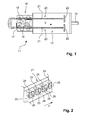
- Fig. 1
- Eine Auspressvorrichtung im Grundriss; und
- Fig. 2
- ein Abschnitt einer Kolbenstange in perspektivischer Darstellung.
- Grundsätzlich sind in den Figuren gleiche Teile mit den gleichen Bezugszeichen versehen.
- Die in den
Figuren 1 und 2 dargestellte Auspressvorrichtung 11 dient dem Auspressen einer Masse aus einem Gebinde, das in einem Aufnahmeraum 13 der Auspressvorrichtung 11 auswechselbar angeordnet ist. Die Auspressvorrichtung 11 weist zwei Kolbenstangen 21 auf, die an ihren freien Enden jeweils einen Druckteller 22 zum Auspressen der im Gebinde befindlichen Masse aufweisen. Entlang der Längserstreckung der Kolbenstangen 21 weisen diese jeweils eine Profilierung 17 auf, die von mehreren im gleichmässigen Abstand zueinander beabstandeten, die die Kolbenstange 21 durchsetzenden Durchgangslöchern 24 gebildet ist. - Weiter weist die Auspressvorrichtung 11 eine Antriebseinheit 16 für die Kolbenstangen 21 auf, die beispielsweise einen Elektromotor als Antrieb, ein Übersetzungsgetriebe und zwei, von dem Antrieb angetriebene, miteinander und mit den Durchgangslöchern 24 der Kolbenstangen 21 kämmende Zahnräder 18 als Antriebsmittel 17 umfasst. Bei Betätigung des Antriebs werden die Zahnräder 18 in Rotation versetzt, welche mit ihren Zähnen als Eingreifmittel gleichzeitig mit den Durchgangslöchern der gelochten Kolbenstangen 21 kämmen, so dass beide Kolbenstangen 21 von den Zahnrädern 18 zum Auspressen der Masse vorgeschoben werden. Die dabei aus dem Gebinde ausgebrachte Masse tritt aus der Ausgabeöffnung 19 der Auspressvorrichtung 11 aus.
- Die Zähne der beiden Zahnräder 18 weisen jeweils eine Evolventenkontur auf. Beispielsweise über eine Polumkehr des Elektromotors beziehungsweise durch Umschaltung des Antriebs werden die Zahnräder 18 entgegen der Rotationsrichtung für den Vorschub der Kolbenstangen 21 rotiert, so dass die Kolbenstangen 21 wieder in eine Ausgangsstellung für einen Wechsel des Gebindes zurückfahrbar sind.
- Alternativ umfasst der Antrieb einen beispielsweise manuell betätigbaren Hebelmechanismus, der gleichzeitig das mit zumindest einer der gelochten Kolbenstangen kämmende, Eingriffsmittel umfassende Antriebsmittel 17 für den Vorschub derselben aufweist.
- Wie in der
Figur 2 ersichtlich, sind die Durchgangslöcher 24 im Öffnungsquerschnitt rechteckig. Die Seitenkanten 25 und 26 eines jeden Durchgangslochs 24, welche in Längserstreckung beziehungsweise in Vorschubrichtung V der Kolbenstangen 21 einander gegenüberliegen und dem kämmenden Antriebsmittel 17 zugewandt sind, sind jeweils mit einer Abkantung versehen. Somit sind die Durchgangslöcher 24 in Längserstreckung der Kolbenstangen 21 gegenüber dem annähernd quadratischen Öffnungsquerschnitt in Richtung der Längserstreckung der Kolbenstangen 21, jeweils auf der dem Antriebsmittel 17 zugewandten Seite der Kolbenstangen 21 aufgeweitet.
Claims (6)
- Auspressvorrichtung für Massen enthaltende Gebinde mit zumindest einer Kolbenstange (21), die entlang ihrer Längserstreckung eine Profilierung (23) aufweist, und
mit einer Antriebseinheit (16) für die zumindest eine Kolbenstange (21) mit einem mit der Profilierung (23) der zumindest einen Kolbenstange (21) kämmenden Antriebsmittel (17), dadurch gekennzeichnet, dass
die Profilierung (23) der zumindest einen Kolbenstange (21) von mehreren im gleichmässigen Abstand zueinander beabstandeten, die Kolbenstange (21) durchsetzenden Durchgangslöchern (24) gebildet ist, in welche Eingriffsmittel des Antriebsmittels (17) für den Vorschub der zumindest einen Kolbenstange (21) eingreifen. - Auspressvorrichtung nach Anspruch 1, dadurch gekennzeichnet, dass das Antriebsmittel (17) zumindest ein Zahnrad (18) ist, wobei die Zähne des zumindest einen Zahnrades (18) die Eingriffsmittel sind.
- Auspressvorrichtung nach Anspruch 2, dadurch gekennzeichnet, dass die Zähne des zumindest einen Zahnrades (18) eine Evolventenkontur aufweisen.
- Auspressvorrichtung nach einem der Ansprüche 1 bis 3, dadurch gekennzeichnet, dass die Durchgangslöcher (24) im Öffnungsquerschnitt rechteckig sind.
- Auspressvorrichtung nach einem der Ansprüche 1 bis 3, dadurch gekennzeichnet, dass zumindest die in Vorschubrichtung (V) der zumindest einen Kolbenstange (21) abgewandte Seitenkante (25) eines jeden Durchgangslochs (24), welche dem kämmenden Antriebsmittel (17) zugewandt ist, mit einer Abkantung versehen ist.
- Auspressvorrichtung nach einem der Ansprüche 1 bis 3, dadurch gekennzeichnet, dass zumindest zwei einander gegenüberliegenden Seitenkanten (25, 26) eines jeden Durchgangslochs (24), welche in Längserstreckung der zumindest einen Kolbenstange (21) einander gegenüberliegenden und dem kämmenden Antriebsmittel (17) zugewandt sind, jeweils mit einer Abkantung versehen sind.
Applications Claiming Priority (1)
| Application Number | Priority Date | Filing Date | Title |
|---|---|---|---|
| DE102008043538A DE102008043538A1 (de) | 2008-11-07 | 2008-11-07 | Auspressvorrichtung |
Publications (2)
| Publication Number | Publication Date |
|---|---|
| EP2184113A1 true EP2184113A1 (de) | 2010-05-12 |
| EP2184113B1 EP2184113B1 (de) | 2012-03-14 |
Family
ID=41404468
Family Applications (1)
| Application Number | Title | Priority Date | Filing Date |
|---|---|---|---|
| EP09172496A Active EP2184113B1 (de) | 2008-11-07 | 2009-10-08 | Auspressvorrichtung |
Country Status (8)
| Country | Link |
|---|---|
| US (1) | US9878345B2 (de) |
| EP (1) | EP2184113B1 (de) |
| JP (1) | JP2010110758A (de) |
| AT (1) | ATE549096T1 (de) |
| AU (1) | AU2009233649B2 (de) |
| CA (1) | CA2684164A1 (de) |
| DE (1) | DE102008043538A1 (de) |
| ES (1) | ES2380305T3 (de) |
Families Citing this family (2)
| Publication number | Priority date | Publication date | Assignee | Title |
|---|---|---|---|---|
| WO2016057647A1 (en) * | 2014-10-07 | 2016-04-14 | Westrock Mwv, Llc | Indexing dose dispensing device |
| CN108190261A (zh) * | 2018-01-24 | 2018-06-22 | 佛山科学技术学院 | 一种手持式电动管料推送器 |
Citations (8)
| Publication number | Priority date | Publication date | Assignee | Title |
|---|---|---|---|---|
| US2093387A (en) * | 1936-05-16 | 1937-09-14 | Lubrication Corp | Lubricating device |
| US2240046A (en) * | 1939-09-25 | 1941-04-29 | Marra Anthony | Liquid gun |
| FR918076A (fr) * | 1944-12-01 | 1947-01-29 | Appareil à délivrer du mastic de vitrier et à mastiquer les vitres de fenêtres | |
| CH248156A (de) * | 1944-12-01 | 1947-04-30 | F Benz Ernst | Apparat zum Kitten von Fensterscheiben. |
| DE2227930B1 (de) | 1972-06-08 | 1973-08-30 | Rudolf 7057 Winnenden Blieberger | Spritzgerat, insbesondere fur Kitt |
| US4318499A (en) * | 1980-08-18 | 1982-03-09 | Hamilton Joel A | Retainer and propulsion apparatus carried in a self-contained handle for use with a removable cartridge |
| JP2001317214A (ja) * | 2000-05-02 | 2001-11-16 | Koichi Hagiwara | コーキングガン |
| DE20309471U1 (de) * | 2003-06-20 | 2004-01-15 | Steinel Gmbh & Co. Kg | Kartuschenpresse |
Family Cites Families (24)
| Publication number | Priority date | Publication date | Assignee | Title |
|---|---|---|---|---|
| US654868A (en) * | 1900-04-27 | 1900-07-31 | Elum Ballinger | Pump. |
| US679983A (en) * | 1900-11-28 | 1901-08-06 | Charles E O'neil | Decorating-machine. |
| US975660A (en) * | 1910-03-21 | 1910-11-15 | Samuel T Waggoner | Reel for drying clothes, &c. |
| US1700364A (en) * | 1925-09-28 | 1929-01-29 | Mabel R Bishop | Appliance for dispensing soft and plastic material |
| US3747806A (en) * | 1971-11-17 | 1973-07-24 | H Goings | Dispenser for collapsible tubes |
| CH562942A5 (de) * | 1972-06-08 | 1975-06-13 | Blieberger Rudolf | |
| LU68217A1 (de) * | 1973-08-13 | 1975-05-21 | ||
| JPS5090967U (de) * | 1973-12-27 | 1975-07-31 | ||
| US3938474A (en) * | 1974-12-13 | 1976-02-17 | Goings Harford E | Dispenser for collapsible tubes |
| US4397199A (en) * | 1980-12-17 | 1983-08-09 | Gebr. Eickhoff, Maschinenfabrik Und Eisengiesserei, M.B.H. | Gear rack for a mining machine |
| JPS58137465A (ja) * | 1982-02-10 | 1983-08-15 | Katsuyuki Totsu | コ−キング材注出装置 |
| DE3736485A1 (de) * | 1987-10-28 | 1989-05-11 | Eickhoff Geb | Zahn- bzw. triebstockstange zum fahren und/oder fuehren eines walzenladers |
| DE4029011A1 (de) * | 1990-09-13 | 1992-03-19 | Webasto Ag Fahrzeugtechnik | Flexible kunststoff-zahnstange |
| DE9200521U1 (de) * | 1991-11-12 | 1993-03-25 | Thera Patent GmbH & Co KG Gesellschaft für industrielle Schutzrechte, 8031 Seefeld | Behälter für fließfähige Substanzen |
| JP2567292Y2 (ja) * | 1992-01-07 | 1998-04-02 | 株式会社岡村製作所 | 棚板等の昇降装置 |
| US5421663A (en) * | 1993-08-11 | 1995-06-06 | Bravo; Sergio M. | Butter dispenser |
| US5582067A (en) * | 1995-10-25 | 1996-12-10 | Delco Electronics Corporation | Integral rotary drive mechanism |
| US5735437A (en) * | 1996-01-22 | 1998-04-07 | Minnesota Mining And Manufacturing | Lockable, hand-held dispenser and mixing tray for dispensing small quantities of material |
| JP3477476B2 (ja) * | 1997-02-14 | 2003-12-10 | 陸男 高橋 | コーキングガン |
| US6338523B1 (en) * | 1999-11-23 | 2002-01-15 | Happijac Company | Sliding mechanisms and systems |
| US6837642B1 (en) * | 2003-03-28 | 2005-01-04 | Chia-Sheng Lin | Length adjustment mechanism of expandable rod |
| US6938799B1 (en) * | 2003-08-11 | 2005-09-06 | Kenneth R. Berntsen | Sealant/adhesive gun |
| JP2005097961A (ja) * | 2003-09-25 | 2005-04-14 | Yasumitsu Kubo | シーリングガン |
| DE102006037623B4 (de) * | 2006-08-10 | 2010-06-02 | Henkel Ag & Co. Kgaa | Kartuschenpistole |
-
2008
- 2008-11-07 DE DE102008043538A patent/DE102008043538A1/de not_active Withdrawn
-
2009
- 2009-10-08 EP EP09172496A patent/EP2184113B1/de active Active
- 2009-10-08 ES ES09172496T patent/ES2380305T3/es active Active
- 2009-10-08 AT AT09172496T patent/ATE549096T1/de active
- 2009-10-29 CA CA2684164A patent/CA2684164A1/en not_active Abandoned
- 2009-11-04 AU AU2009233649A patent/AU2009233649B2/en active Active
- 2009-11-05 US US12/613,311 patent/US9878345B2/en active Active
- 2009-11-05 JP JP2009254232A patent/JP2010110758A/ja active Pending
Patent Citations (8)
| Publication number | Priority date | Publication date | Assignee | Title |
|---|---|---|---|---|
| US2093387A (en) * | 1936-05-16 | 1937-09-14 | Lubrication Corp | Lubricating device |
| US2240046A (en) * | 1939-09-25 | 1941-04-29 | Marra Anthony | Liquid gun |
| FR918076A (fr) * | 1944-12-01 | 1947-01-29 | Appareil à délivrer du mastic de vitrier et à mastiquer les vitres de fenêtres | |
| CH248156A (de) * | 1944-12-01 | 1947-04-30 | F Benz Ernst | Apparat zum Kitten von Fensterscheiben. |
| DE2227930B1 (de) | 1972-06-08 | 1973-08-30 | Rudolf 7057 Winnenden Blieberger | Spritzgerat, insbesondere fur Kitt |
| US4318499A (en) * | 1980-08-18 | 1982-03-09 | Hamilton Joel A | Retainer and propulsion apparatus carried in a self-contained handle for use with a removable cartridge |
| JP2001317214A (ja) * | 2000-05-02 | 2001-11-16 | Koichi Hagiwara | コーキングガン |
| DE20309471U1 (de) * | 2003-06-20 | 2004-01-15 | Steinel Gmbh & Co. Kg | Kartuschenpresse |
Also Published As
| Publication number | Publication date |
|---|---|
| US20100116851A1 (en) | 2010-05-13 |
| EP2184113B1 (de) | 2012-03-14 |
| ATE549096T1 (de) | 2012-03-15 |
| ES2380305T3 (es) | 2012-05-10 |
| CA2684164A1 (en) | 2010-05-07 |
| US9878345B2 (en) | 2018-01-30 |
| AU2009233649A1 (en) | 2010-05-27 |
| DE102008043538A1 (de) | 2010-05-12 |
| JP2010110758A (ja) | 2010-05-20 |
| AU2009233649B2 (en) | 2011-09-08 |
Similar Documents
| Publication | Publication Date | Title |
|---|---|---|
| DE3428202C2 (de) | ||
| CH648255A5 (de) | Geraet zum abgeben von mehrkomponentenmassen. | |
| DE910218C (de) | Mischer fuer Kautschuk- oder aehnliche plastische Massen | |
| EP2059185A1 (de) | Gerät zum erzeugen einer mehrkomponentenmasse | |
| EP0232733A2 (de) | Zweikomponenten-Austrageinrichtung | |
| EP2050511A1 (de) | Auspressvorrichtung | |
| EP2298453A2 (de) | Auspressvorrichtung | |
| DE4026685A1 (de) | Verfahren und vorrichtung zum zusammenfuehren zweier pastoeser massen | |
| DE10207145B4 (de) | Vorrichtung zum Dispergieren und Aufschmelzen fließfähiger Stoffe | |
| EP2050510B1 (de) | Auspressvorrichtung | |
| EP2184113B1 (de) | Auspressvorrichtung | |
| EP0620047A1 (de) | Kolben für Auspressgeräte | |
| DE9100054U1 (de) | Vorratspackung für zweikomponentiges Polyurethanmaterial | |
| DE202006014187U1 (de) | Vorrichtung zum Vermischen einer Binder- und einer Härter-Komponente zur Herstellung einer gebrauchsfertigen Spachtelmasse | |
| DE102010051923A1 (de) | Vorrichtung zum verspannenden Verbinden von mit Abstand hintereinander liegenden Bauteilen | |
| EP2295152B1 (de) | Auspressvorrichtung | |
| EP2931624B1 (de) | Austragvorrichtung für eine mehrkomponentenmasse | |
| DE8028428U1 (de) | Vorrichtung zur gemeinsamen Abgabe wenigstens zweier in getrennten Behaeltern gelagerten Substanzen | |
| EP2868392A1 (de) | Hülse, Austragseinrichtung umfassend die Hülse und Verfahren | |
| DE828483C (de) | Presse zum Auspressen von Fluessigkeit aus einer fluessigkeits- haltigen Masse, z.B.zum Auspressen von OEl und Wasser aus gekochter Heringsmasse | |
| EP2885088B1 (de) | Austragvorrichtung | |
| DE739278C (de) | Vorrichtung zum Homogenisieren und Auspressen von plastischen bis kruemelig weichen Massen, Emulsionen u. dgl. | |
| DE29907201U1 (de) | Vorrichtung zum Auspressen und dosierten Abgeben von fließfähigen Massen | |
| DE1939518A1 (de) | Einrichtung fuer die wechselseitige Bewegungsuebertragung,in der Art eines Zahnstangen- und -Ritzel-Triebs | |
| DE10034998C2 (de) | Zahnradextruder |
Legal Events
| Date | Code | Title | Description |
|---|---|---|---|
| PUAI | Public reference made under article 153(3) epc to a published international application that has entered the european phase |
Free format text: ORIGINAL CODE: 0009012 |
|
| AK | Designated contracting states |
Kind code of ref document: A1 Designated state(s): AT BE BG CH CY CZ DE DK EE ES FI FR GB GR HR HU IE IS IT LI LT LU LV MC MK MT NL NO PL PT RO SE SI SK SM TR |
|
| AX | Request for extension of the european patent |
Extension state: AL BA RS |
|
| 17P | Request for examination filed |
Effective date: 20101112 |
|
| 17Q | First examination report despatched |
Effective date: 20110222 |
|
| GRAP | Despatch of communication of intention to grant a patent |
Free format text: ORIGINAL CODE: EPIDOSNIGR1 |
|
| RIC1 | Information provided on ipc code assigned before grant |
Ipc: B05C 17/01 20060101AFI20111021BHEP |
|
| GRAS | Grant fee paid |
Free format text: ORIGINAL CODE: EPIDOSNIGR3 |
|
| GRAA | (expected) grant |
Free format text: ORIGINAL CODE: 0009210 |
|
| AK | Designated contracting states |
Kind code of ref document: B1 Designated state(s): AT BE BG CH CY CZ DE DK EE ES FI FR GB GR HR HU IE IS IT LI LT LU LV MC MK MT NL NO PL PT RO SE SI SK SM TR |
|
| REG | Reference to a national code |
Ref country code: GB Ref legal event code: FG4D Free format text: NOT ENGLISH |
|
| REG | Reference to a national code |
Ref country code: AT Ref legal event code: REF Ref document number: 549096 Country of ref document: AT Kind code of ref document: T Effective date: 20120315 Ref country code: CH Ref legal event code: EP |
|
| REG | Reference to a national code |
Ref country code: IE Ref legal event code: FG4D Free format text: LANGUAGE OF EP DOCUMENT: GERMAN |
|
| REG | Reference to a national code |
Ref country code: ES Ref legal event code: FG2A Ref document number: 2380305 Country of ref document: ES Kind code of ref document: T3 Effective date: 20120510 |
|
| REG | Reference to a national code |
Ref country code: DE Ref legal event code: R096 Ref document number: 502009003017 Country of ref document: DE Effective date: 20120516 |
|
| REG | Reference to a national code |
Ref country code: NL Ref legal event code: VDEP Effective date: 20120314 |
|
| PG25 | Lapsed in a contracting state [announced via postgrant information from national office to epo] |
Ref country code: LT Free format text: LAPSE BECAUSE OF FAILURE TO SUBMIT A TRANSLATION OF THE DESCRIPTION OR TO PAY THE FEE WITHIN THE PRESCRIBED TIME-LIMIT Effective date: 20120314 Ref country code: NO Free format text: LAPSE BECAUSE OF FAILURE TO SUBMIT A TRANSLATION OF THE DESCRIPTION OR TO PAY THE FEE WITHIN THE PRESCRIBED TIME-LIMIT Effective date: 20120614 Ref country code: HR Free format text: LAPSE BECAUSE OF FAILURE TO SUBMIT A TRANSLATION OF THE DESCRIPTION OR TO PAY THE FEE WITHIN THE PRESCRIBED TIME-LIMIT Effective date: 20120314 |
|
| LTIE | Lt: invalidation of european patent or patent extension |
Effective date: 20120314 |
|
| PG25 | Lapsed in a contracting state [announced via postgrant information from national office to epo] |
Ref country code: GR Free format text: LAPSE BECAUSE OF FAILURE TO SUBMIT A TRANSLATION OF THE DESCRIPTION OR TO PAY THE FEE WITHIN THE PRESCRIBED TIME-LIMIT Effective date: 20120615 Ref country code: FI Free format text: LAPSE BECAUSE OF FAILURE TO SUBMIT A TRANSLATION OF THE DESCRIPTION OR TO PAY THE FEE WITHIN THE PRESCRIBED TIME-LIMIT Effective date: 20120314 Ref country code: LV Free format text: LAPSE BECAUSE OF FAILURE TO SUBMIT A TRANSLATION OF THE DESCRIPTION OR TO PAY THE FEE WITHIN THE PRESCRIBED TIME-LIMIT Effective date: 20120314 |
|
| PG25 | Lapsed in a contracting state [announced via postgrant information from national office to epo] |
Ref country code: CY Free format text: LAPSE BECAUSE OF FAILURE TO SUBMIT A TRANSLATION OF THE DESCRIPTION OR TO PAY THE FEE WITHIN THE PRESCRIBED TIME-LIMIT Effective date: 20120314 |
|
| PG25 | Lapsed in a contracting state [announced via postgrant information from national office to epo] |
Ref country code: RO Free format text: LAPSE BECAUSE OF FAILURE TO SUBMIT A TRANSLATION OF THE DESCRIPTION OR TO PAY THE FEE WITHIN THE PRESCRIBED TIME-LIMIT Effective date: 20120314 Ref country code: SI Free format text: LAPSE BECAUSE OF FAILURE TO SUBMIT A TRANSLATION OF THE DESCRIPTION OR TO PAY THE FEE WITHIN THE PRESCRIBED TIME-LIMIT Effective date: 20120314 Ref country code: IS Free format text: LAPSE BECAUSE OF FAILURE TO SUBMIT A TRANSLATION OF THE DESCRIPTION OR TO PAY THE FEE WITHIN THE PRESCRIBED TIME-LIMIT Effective date: 20120714 Ref country code: PL Free format text: LAPSE BECAUSE OF FAILURE TO SUBMIT A TRANSLATION OF THE DESCRIPTION OR TO PAY THE FEE WITHIN THE PRESCRIBED TIME-LIMIT Effective date: 20120314 Ref country code: SE Free format text: LAPSE BECAUSE OF FAILURE TO SUBMIT A TRANSLATION OF THE DESCRIPTION OR TO PAY THE FEE WITHIN THE PRESCRIBED TIME-LIMIT Effective date: 20120314 Ref country code: EE Free format text: LAPSE BECAUSE OF FAILURE TO SUBMIT A TRANSLATION OF THE DESCRIPTION OR TO PAY THE FEE WITHIN THE PRESCRIBED TIME-LIMIT Effective date: 20120314 Ref country code: CZ Free format text: LAPSE BECAUSE OF FAILURE TO SUBMIT A TRANSLATION OF THE DESCRIPTION OR TO PAY THE FEE WITHIN THE PRESCRIBED TIME-LIMIT Effective date: 20120314 |
|
| PG25 | Lapsed in a contracting state [announced via postgrant information from national office to epo] |
Ref country code: SK Free format text: LAPSE BECAUSE OF FAILURE TO SUBMIT A TRANSLATION OF THE DESCRIPTION OR TO PAY THE FEE WITHIN THE PRESCRIBED TIME-LIMIT Effective date: 20120314 Ref country code: PT Free format text: LAPSE BECAUSE OF FAILURE TO SUBMIT A TRANSLATION OF THE DESCRIPTION OR TO PAY THE FEE WITHIN THE PRESCRIBED TIME-LIMIT Effective date: 20120716 |
|
| PLBE | No opposition filed within time limit |
Free format text: ORIGINAL CODE: 0009261 |
|
| STAA | Information on the status of an ep patent application or granted ep patent |
Free format text: STATUS: NO OPPOSITION FILED WITHIN TIME LIMIT |
|
| PG25 | Lapsed in a contracting state [announced via postgrant information from national office to epo] |
Ref country code: DK Free format text: LAPSE BECAUSE OF FAILURE TO SUBMIT A TRANSLATION OF THE DESCRIPTION OR TO PAY THE FEE WITHIN THE PRESCRIBED TIME-LIMIT Effective date: 20120314 Ref country code: NL Free format text: LAPSE BECAUSE OF FAILURE TO SUBMIT A TRANSLATION OF THE DESCRIPTION OR TO PAY THE FEE WITHIN THE PRESCRIBED TIME-LIMIT Effective date: 20120314 |
|
| 26N | No opposition filed |
Effective date: 20121217 |
|
| REG | Reference to a national code |
Ref country code: DE Ref legal event code: R097 Ref document number: 502009003017 Country of ref document: DE Effective date: 20121217 |
|
| BERE | Be: lapsed |
Owner name: HILTI AKTIENGESELLSCHAFT Effective date: 20121031 |
|
| PG25 | Lapsed in a contracting state [announced via postgrant information from national office to epo] |
Ref country code: MC Free format text: LAPSE BECAUSE OF NON-PAYMENT OF DUE FEES Effective date: 20121031 |
|
| REG | Reference to a national code |
Ref country code: IE Ref legal event code: MM4A |
|
| PG25 | Lapsed in a contracting state [announced via postgrant information from national office to epo] |
Ref country code: IE Free format text: LAPSE BECAUSE OF NON-PAYMENT OF DUE FEES Effective date: 20121008 Ref country code: BG Free format text: LAPSE BECAUSE OF FAILURE TO SUBMIT A TRANSLATION OF THE DESCRIPTION OR TO PAY THE FEE WITHIN THE PRESCRIBED TIME-LIMIT Effective date: 20120614 Ref country code: BE Free format text: LAPSE BECAUSE OF NON-PAYMENT OF DUE FEES Effective date: 20121031 |
|
| PG25 | Lapsed in a contracting state [announced via postgrant information from national office to epo] |
Ref country code: MT Free format text: LAPSE BECAUSE OF FAILURE TO SUBMIT A TRANSLATION OF THE DESCRIPTION OR TO PAY THE FEE WITHIN THE PRESCRIBED TIME-LIMIT Effective date: 20120314 |
|
| PG25 | Lapsed in a contracting state [announced via postgrant information from national office to epo] |
Ref country code: TR Free format text: LAPSE BECAUSE OF FAILURE TO SUBMIT A TRANSLATION OF THE DESCRIPTION OR TO PAY THE FEE WITHIN THE PRESCRIBED TIME-LIMIT Effective date: 20120314 |
|
| PG25 | Lapsed in a contracting state [announced via postgrant information from national office to epo] |
Ref country code: SM Free format text: LAPSE BECAUSE OF FAILURE TO SUBMIT A TRANSLATION OF THE DESCRIPTION OR TO PAY THE FEE WITHIN THE PRESCRIBED TIME-LIMIT Effective date: 20120314 Ref country code: LU Free format text: LAPSE BECAUSE OF NON-PAYMENT OF DUE FEES Effective date: 20121008 |
|
| PG25 | Lapsed in a contracting state [announced via postgrant information from national office to epo] |
Ref country code: HU Free format text: LAPSE BECAUSE OF FAILURE TO SUBMIT A TRANSLATION OF THE DESCRIPTION OR TO PAY THE FEE WITHIN THE PRESCRIBED TIME-LIMIT Effective date: 20091008 |
|
| PG25 | Lapsed in a contracting state [announced via postgrant information from national office to epo] |
Ref country code: MK Free format text: LAPSE BECAUSE OF FAILURE TO SUBMIT A TRANSLATION OF THE DESCRIPTION OR TO PAY THE FEE WITHIN THE PRESCRIBED TIME-LIMIT Effective date: 20120314 |
|
| REG | Reference to a national code |
Ref country code: FR Ref legal event code: PLFP Year of fee payment: 8 |
|
| REG | Reference to a national code |
Ref country code: FR Ref legal event code: PLFP Year of fee payment: 9 |
|
| REG | Reference to a national code |
Ref country code: FR Ref legal event code: PLFP Year of fee payment: 10 |
|
| P01 | Opt-out of the competence of the unified patent court (upc) registered |
Effective date: 20230830 |
|
| REG | Reference to a national code |
Ref country code: CH Ref legal event code: U11 Free format text: ST27 STATUS EVENT CODE: U-0-0-U10-U11 (AS PROVIDED BY THE NATIONAL OFFICE) Effective date: 20251101 |
|
| PGFP | Annual fee paid to national office [announced via postgrant information from national office to epo] |
Ref country code: DE Payment date: 20251021 Year of fee payment: 17 |
|
| PGFP | Annual fee paid to national office [announced via postgrant information from national office to epo] |
Ref country code: GB Payment date: 20251022 Year of fee payment: 17 |
|
| PGFP | Annual fee paid to national office [announced via postgrant information from national office to epo] |
Ref country code: AT Payment date: 20251022 Year of fee payment: 17 |
|
| PGFP | Annual fee paid to national office [announced via postgrant information from national office to epo] |
Ref country code: IT Payment date: 20251024 Year of fee payment: 17 |
|
| PGFP | Annual fee paid to national office [announced via postgrant information from national office to epo] |
Ref country code: FR Payment date: 20251029 Year of fee payment: 17 |
|
| PGFP | Annual fee paid to national office [announced via postgrant information from national office to epo] |
Ref country code: CH Payment date: 20251101 Year of fee payment: 17 |
|
| PGFP | Annual fee paid to national office [announced via postgrant information from national office to epo] |
Ref country code: ES Payment date: 20251210 Year of fee payment: 17 |