EP2154443A1 - Installation d'alimentation en eau chaude pour le chauffage - Google Patents
Installation d'alimentation en eau chaude pour le chauffage Download PDFInfo
- Publication number
- EP2154443A1 EP2154443A1 EP08738756A EP08738756A EP2154443A1 EP 2154443 A1 EP2154443 A1 EP 2154443A1 EP 08738756 A EP08738756 A EP 08738756A EP 08738756 A EP08738756 A EP 08738756A EP 2154443 A1 EP2154443 A1 EP 2154443A1
- Authority
- EP
- European Patent Office
- Prior art keywords
- hot water
- tank
- heating
- heat exchanger
- supply apparatus
- Prior art date
- Legal status (The legal status is an assumption and is not a legal conclusion. Google has not performed a legal analysis and makes no representation as to the accuracy of the status listed.)
- Withdrawn
Links
Images


Classifications
-
- F—MECHANICAL ENGINEERING; LIGHTING; HEATING; WEAPONS; BLASTING
- F28—HEAT EXCHANGE IN GENERAL
- F28D—HEAT-EXCHANGE APPARATUS, NOT PROVIDED FOR IN ANOTHER SUBCLASS, IN WHICH THE HEAT-EXCHANGE MEDIA DO NOT COME INTO DIRECT CONTACT
- F28D7/00—Heat-exchange apparatus having stationary tubular conduit assemblies for both heat-exchange media, the media being in contact with different sides of a conduit wall
- F28D7/02—Heat-exchange apparatus having stationary tubular conduit assemblies for both heat-exchange media, the media being in contact with different sides of a conduit wall the conduits being helically coiled
- F28D7/024—Heat-exchange apparatus having stationary tubular conduit assemblies for both heat-exchange media, the media being in contact with different sides of a conduit wall the conduits being helically coiled the conduits of only one medium being helically coiled tubes, the coils having a cylindrical configuration
-
- F—MECHANICAL ENGINEERING; LIGHTING; HEATING; WEAPONS; BLASTING
- F24—HEATING; RANGES; VENTILATING
- F24D—DOMESTIC- OR SPACE-HEATING SYSTEMS, e.g. CENTRAL HEATING SYSTEMS; DOMESTIC HOT-WATER SUPPLY SYSTEMS; ELEMENTS OR COMPONENTS THEREFOR
- F24D11/00—Central heating systems using heat accumulated in storage masses
- F24D11/02—Central heating systems using heat accumulated in storage masses using heat pumps
- F24D11/0214—Central heating systems using heat accumulated in storage masses using heat pumps water heating system
- F24D11/0228—Central heating systems using heat accumulated in storage masses using heat pumps water heating system combined with conventional heater
-
- F—MECHANICAL ENGINEERING; LIGHTING; HEATING; WEAPONS; BLASTING
- F24—HEATING; RANGES; VENTILATING
- F24D—DOMESTIC- OR SPACE-HEATING SYSTEMS, e.g. CENTRAL HEATING SYSTEMS; DOMESTIC HOT-WATER SUPPLY SYSTEMS; ELEMENTS OR COMPONENTS THEREFOR
- F24D17/00—Domestic hot-water supply systems
- F24D17/02—Domestic hot-water supply systems using heat pumps
-
- F—MECHANICAL ENGINEERING; LIGHTING; HEATING; WEAPONS; BLASTING
- F28—HEAT EXCHANGE IN GENERAL
- F28D—HEAT-EXCHANGE APPARATUS, NOT PROVIDED FOR IN ANOTHER SUBCLASS, IN WHICH THE HEAT-EXCHANGE MEDIA DO NOT COME INTO DIRECT CONTACT
- F28D20/00—Heat storage plants or apparatus in general; Regenerative heat-exchange apparatus not covered by groups F28D17/00 or F28D19/00
- F28D20/0034—Heat storage plants or apparatus in general; Regenerative heat-exchange apparatus not covered by groups F28D17/00 or F28D19/00 using liquid heat storage material
- F28D20/0039—Heat storage plants or apparatus in general; Regenerative heat-exchange apparatus not covered by groups F28D17/00 or F28D19/00 using liquid heat storage material with stratification of the heat storage material
-
- F—MECHANICAL ENGINEERING; LIGHTING; HEATING; WEAPONS; BLASTING
- F28—HEAT EXCHANGE IN GENERAL
- F28D—HEAT-EXCHANGE APPARATUS, NOT PROVIDED FOR IN ANOTHER SUBCLASS, IN WHICH THE HEAT-EXCHANGE MEDIA DO NOT COME INTO DIRECT CONTACT
- F28D7/00—Heat-exchange apparatus having stationary tubular conduit assemblies for both heat-exchange media, the media being in contact with different sides of a conduit wall
- F28D7/02—Heat-exchange apparatus having stationary tubular conduit assemblies for both heat-exchange media, the media being in contact with different sides of a conduit wall the conduits being helically coiled
- F28D7/028—Heat-exchange apparatus having stationary tubular conduit assemblies for both heat-exchange media, the media being in contact with different sides of a conduit wall the conduits being helically coiled the conduits of at least one medium being helically coiled, the coils having a conical configuration
-
- F—MECHANICAL ENGINEERING; LIGHTING; HEATING; WEAPONS; BLASTING
- F24—HEATING; RANGES; VENTILATING
- F24D—DOMESTIC- OR SPACE-HEATING SYSTEMS, e.g. CENTRAL HEATING SYSTEMS; DOMESTIC HOT-WATER SUPPLY SYSTEMS; ELEMENTS OR COMPONENTS THEREFOR
- F24D2200/00—Heat sources or energy sources
- F24D2200/08—Electric heater
-
- F—MECHANICAL ENGINEERING; LIGHTING; HEATING; WEAPONS; BLASTING
- F24—HEATING; RANGES; VENTILATING
- F24D—DOMESTIC- OR SPACE-HEATING SYSTEMS, e.g. CENTRAL HEATING SYSTEMS; DOMESTIC HOT-WATER SUPPLY SYSTEMS; ELEMENTS OR COMPONENTS THEREFOR
- F24D2200/00—Heat sources or energy sources
- F24D2200/12—Heat pump
-
- F—MECHANICAL ENGINEERING; LIGHTING; HEATING; WEAPONS; BLASTING
- F24—HEATING; RANGES; VENTILATING
- F24D—DOMESTIC- OR SPACE-HEATING SYSTEMS, e.g. CENTRAL HEATING SYSTEMS; DOMESTIC HOT-WATER SUPPLY SYSTEMS; ELEMENTS OR COMPONENTS THEREFOR
- F24D2220/00—Components of central heating installations excluding heat sources
- F24D2220/06—Heat exchangers
-
- F—MECHANICAL ENGINEERING; LIGHTING; HEATING; WEAPONS; BLASTING
- F24—HEATING; RANGES; VENTILATING
- F24D—DOMESTIC- OR SPACE-HEATING SYSTEMS, e.g. CENTRAL HEATING SYSTEMS; DOMESTIC HOT-WATER SUPPLY SYSTEMS; ELEMENTS OR COMPONENTS THEREFOR
- F24D2220/00—Components of central heating installations excluding heat sources
- F24D2220/08—Storage tanks
-
- F—MECHANICAL ENGINEERING; LIGHTING; HEATING; WEAPONS; BLASTING
- F24—HEATING; RANGES; VENTILATING
- F24D—DOMESTIC- OR SPACE-HEATING SYSTEMS, e.g. CENTRAL HEATING SYSTEMS; DOMESTIC HOT-WATER SUPPLY SYSTEMS; ELEMENTS OR COMPONENTS THEREFOR
- F24D2220/00—Components of central heating installations excluding heat sources
- F24D2220/20—Heat consumers
- F24D2220/2009—Radiators
-
- F—MECHANICAL ENGINEERING; LIGHTING; HEATING; WEAPONS; BLASTING
- F24—HEATING; RANGES; VENTILATING
- F24D—DOMESTIC- OR SPACE-HEATING SYSTEMS, e.g. CENTRAL HEATING SYSTEMS; DOMESTIC HOT-WATER SUPPLY SYSTEMS; ELEMENTS OR COMPONENTS THEREFOR
- F24D2220/00—Components of central heating installations excluding heat sources
- F24D2220/20—Heat consumers
- F24D2220/209—Sanitary water taps
-
- F—MECHANICAL ENGINEERING; LIGHTING; HEATING; WEAPONS; BLASTING
- F24—HEATING; RANGES; VENTILATING
- F24D—DOMESTIC- OR SPACE-HEATING SYSTEMS, e.g. CENTRAL HEATING SYSTEMS; DOMESTIC HOT-WATER SUPPLY SYSTEMS; ELEMENTS OR COMPONENTS THEREFOR
- F24D2240/00—Characterizing positions, e.g. of sensors, inlets, outlets
- F24D2240/10—Placed within or inside of
-
- F—MECHANICAL ENGINEERING; LIGHTING; HEATING; WEAPONS; BLASTING
- F28—HEAT EXCHANGE IN GENERAL
- F28D—HEAT-EXCHANGE APPARATUS, NOT PROVIDED FOR IN ANOTHER SUBCLASS, IN WHICH THE HEAT-EXCHANGE MEDIA DO NOT COME INTO DIRECT CONTACT
- F28D20/00—Heat storage plants or apparatus in general; Regenerative heat-exchange apparatus not covered by groups F28D17/00 or F28D19/00
- F28D2020/0065—Details, e.g. particular heat storage tanks, auxiliary members within tanks
- F28D2020/0078—Heat exchanger arrangements
-
- F—MECHANICAL ENGINEERING; LIGHTING; HEATING; WEAPONS; BLASTING
- F28—HEAT EXCHANGE IN GENERAL
- F28D—HEAT-EXCHANGE APPARATUS, NOT PROVIDED FOR IN ANOTHER SUBCLASS, IN WHICH THE HEAT-EXCHANGE MEDIA DO NOT COME INTO DIRECT CONTACT
- F28D20/00—Heat storage plants or apparatus in general; Regenerative heat-exchange apparatus not covered by groups F28D17/00 or F28D19/00
- F28D2020/0065—Details, e.g. particular heat storage tanks, auxiliary members within tanks
- F28D2020/0086—Partitions
-
- Y—GENERAL TAGGING OF NEW TECHNOLOGICAL DEVELOPMENTS; GENERAL TAGGING OF CROSS-SECTIONAL TECHNOLOGIES SPANNING OVER SEVERAL SECTIONS OF THE IPC; TECHNICAL SUBJECTS COVERED BY FORMER USPC CROSS-REFERENCE ART COLLECTIONS [XRACs] AND DIGESTS
- Y02—TECHNOLOGIES OR APPLICATIONS FOR MITIGATION OR ADAPTATION AGAINST CLIMATE CHANGE
- Y02B—CLIMATE CHANGE MITIGATION TECHNOLOGIES RELATED TO BUILDINGS, e.g. HOUSING, HOUSE APPLIANCES OR RELATED END-USER APPLICATIONS
- Y02B10/00—Integration of renewable energy sources in buildings
- Y02B10/70—Hybrid systems, e.g. uninterruptible or back-up power supplies integrating renewable energies
-
- Y—GENERAL TAGGING OF NEW TECHNOLOGICAL DEVELOPMENTS; GENERAL TAGGING OF CROSS-SECTIONAL TECHNOLOGIES SPANNING OVER SEVERAL SECTIONS OF THE IPC; TECHNICAL SUBJECTS COVERED BY FORMER USPC CROSS-REFERENCE ART COLLECTIONS [XRACs] AND DIGESTS
- Y02—TECHNOLOGIES OR APPLICATIONS FOR MITIGATION OR ADAPTATION AGAINST CLIMATE CHANGE
- Y02E—REDUCTION OF GREENHOUSE GAS [GHG] EMISSIONS, RELATED TO ENERGY GENERATION, TRANSMISSION OR DISTRIBUTION
- Y02E60/00—Enabling technologies; Technologies with a potential or indirect contribution to GHG emissions mitigation
- Y02E60/14—Thermal energy storage
Definitions
- the present invention relates to a heating and hot water supply apparatus to be used for heating and hot water supply.
- This heating and hot water supply apparatus includes a heat pump, a hot water tank for storing hot water heated by the heat pump, a heat exchanger placed only in an upper region within the hot water tank, and a heater connected to the heat exchanger.
- the hot water tank is connected to a faucet via a hot water outlet pipe. Opening the faucet allows hot water stored in the hot water tank to be taken out from the faucet.
- the heater performs heating operation by using the hot water stored in the hot water tank. More specifically, when the heating operation is started, a heating medium in the heat exchanger is heated by the hot water contained in the hot water tank. The heated heating medium is fed to the heater to radiate heat indoors from the heater.
- the conventional heating and hot water supply apparatus described above has a problem that with 24-hour heating operation in winter, enough heating cannot be fulfilled in regions, such as Nordic countries, which have high heating loads involving a heating load to hot water supply load ratio of 10 : 1.
- an object of the present invention is to provide a heating and hot water supply apparatus capable of fulfilling enough heating even in regions of high heating loads such as Nordic countries.
- a heating and hot water supply apparatus comprising:
- heating and hot water supply apparatus of this invention when heating operation is started, hot water stored in the hot water tank flows to a heating terminal via a circulation path, and returns to the hot water tank again. Thus, heat of the hot water is radiated indoors via the heating terminal. That is, the heating terminal directly extracts heat of the hot water in the hot water tank and radiates the heat indoors.
- the heat of the hot water in the hot water tank is supplied to the heating terminal with high efficiency, and the heating and hot water supply apparatus is enabled to fulfill enough heating even in such regions of high heating loads as Nordic countries.
- the hot water tank is a cylindrical-shaped member and an aspect ratio of the hot water tank, which is a ratio of an inner height to an inner diameter of the hot water tank, is 4.0 or more.
- the in-tank heat exchanger is so arranged and configured that temperature of stored water stored in the hot water tank, which temperature varies due to heat exchange between the stored water and flow-through water flowing through the interior of the in-tank heat exchanger, is lower in a lower side in the hot water tank and higher in an upper side in the hot water tank.
- the in-tank heat exchanger is formed of a tubular member, and a lower-side portion of the in-tank heat exchanger is smaller in tubular inner diameter than an upper-side portion of the in-tank heat exchanger and an in-tube water flow velocity of the lower-side portion is higher than an in-tube water flow velocity of the upper-side portion.
- a lower-side portion of the in-tank heat exchanger is formed of an internally grooved tube.
- the in-tank heat exchanger is formed of a coiled tubular member, and a coil density of a lower-side portion of the in-tank heat exchanger is higher than a coil density of an upper-side portion of the in-tank heat exchanger.
- the in-tank heat exchanger is formed of a coiled tubular member, and a portion of the coiled tubular member is formed into a spiral shape in a vertical direction, the spiral shape having a height difference smaller than a tubular outer diameter, such that the spiral shape portion serves as a resistive member against vertical flow of the stored water stored in the hot water tank.
- a baffle member for restricting vertical water flow in the hot water tank is provided at an intermediate height position higher than an opening for a lower-position side water pipe in the hot water tank.
- the baffle member comprises a transverse plate member for vertically dividing an internal space of the hot water tank.
- the baffle member comprises a vertical plate member for diametrally dividing an internal space of the hot water tank.
- the baffle member comprises a transverse plate member for vertically dividing an internal space of the hot water tank and a vertical plate member for diametrally dividing the internal space of the hot water tank.
- the heating and hot water supply apparatus of the invention hot water stored in the hot water tank is fed to the heating terminal through the circulation path so that heat of the hot water is supplied to the heating terminal efficiently without passing through the heat exchanger.
- the heating and hot water supply apparatus is enabled to fulfill enough heating in such regions of high heating loads as Nordic countries where 24-hour heating operation is involved in winter.
- a heating and hot water supply apparatus has a first characteristic that hot water in the hot water tank is not used for purposes involving direct contact with the human body, and hot water heated indirectly by an in-tank heat exchanger provided in the hot water tank is used for purposes involving direct contact with the human body.
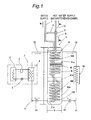
- the heating and hot water supply apparatus includes: a heat pump unit 2 having a compressor 3 for compressing a refrigerant, a radiative heat exchanger 4 for condensing the compressed refrigerant to radiate heat, and an endothermic heat exchanger 6 for evaporating the condensed refrigerant and absorbing heat from the air; and a water storage tank 1 which is connected to the heat pump unit 2 via a lower-position side water pipe 21 and a higher-position side water pipe 22 and in which stored water W 1 , i.e.
- hot water heated by the radiative heat exchanger 4 is stored and moreover which is internally provided with an in-tank heat exchanger 10 for performing heat exchange with the stored water W 1 to heat flow-through water W 2 , i.e. supply hot water flowing through the interior of the in-tank heat exchanger 10, wherein the water storage tank aspect ratio (H/D), i.e., a ratio of the inner height H to the inner diameter D ratio of the water storage tank 1, is set to 4.0 or more.
- H/D water storage tank aspect ratio
- the water storage tank 1 is an example of the hot water tank.
- the in-tank heat exchanger 10 in the water storage tank is an example of the in-tank heat exchanger in the hot water tank.
- hot water to be supplied directly toward the human body as in baths, kitchens, shower baths and the like is obtained by the flow-through water (supply hot water) W 2 flowing through the in-tank heat exchanger 10 provided in the water storage tank 1, and the (scale-containing) in-tank stored water (hot water) W 1 staying within the water storage tank 1 is never supplied directly toward the human body as in the conventional heating and hot water supply apparatus.
- the aspect ratio (H/D) of the water storage tank 1 is set to 4.0 or more to suppress vertical water flows within the water storage tank 1 so that uniformization of water temperatures of the stored water W 1 within the water storage tank 1 is suppressed. Therefore, in the water storage tank 1, water temperature on the lower (bottom portion) side is maintained lower than that of the upper (top portion) side by the most possible extent, making it possible to supply heated water of a relatively low temperature to the radiative heat exchanger 4 of the heat pump unit 2. As a result, heating efficiency by the heat pump unit 2 can be improved.
- Fig. 2 is a graph showing a relationship between the aspect ratio H/D, which is a ratio of the inner height H to the inner diameter D of the water storage tank 1, and the water convection action in the water storage tank 1.
- the graph shows that, generally, the water convection action (vertical water-temperature uniformization action) in the water storage tank 1 becomes more and more active with decreasing aspect ratio H/D (with the inner diameter D going larger, or thicker, relative to the height H) of the water storage tank 1, whereas the water convection action in the water storage tank 1 is suppressed more and more (i.e., vertical uniformization of water temperatures in the water storage tank 1 is suppressed more and more) with increasing aspect ratio H/D (with the height H becoming larger relative to the inner diameter D, hence elongation).
- the suppression tendency of water convection action becomes noticeable as the aspect ratio of the water storage tank 1 goes beyond about 4.0. It is also shown that with the aspect ratio beyond 4.0, the suppression action of the water convection in the water storage tank 1 gently and gradually decreases at a certain level or lower. From such knowledge shown above, the aspect ratio H/D of the water storage tank 1 is specified as 4.0 or more for the heating and hot water supply apparatus of the first embodiment (for conventional heating and hot water supply apparatuses of the same type, the aspect ratio of the water storage tank 1 is about 2.5).
- the aspect ratio (H/D) adoptable for the heating and hot water supply apparatus of the first embodiment should preferably be within an upper limit of 8.0 in terms of restraints of manufacture, transport, installation and the like of the water storage tank 1.
- the aspect ratio H/D of the water storage tank 1 is set to 4.0 or more as described above so that the vertical water flow in the water storage tank 1 is suppressed so as to cause a vertical (upper-and-lower) temperature difference of the hot water in the water storage tank 1, i.e., of the stored water W 1 (lower-side portion W 1b is lower in temperature than upper-side portion W 1a ).
- the vertical temperature difference (upper-side higher and lower-side lower in temperature) creating action for the stored water W 1 in the water storage tank 1 can be facilitated also by a function of the heat exchanger 10 itself in the water tank. Below explained is an actualization of this scheme.
- a water-supply side pipe line 7 running to the in-tank heat exchanger 10 is vertically provided in a straight pipe shape up to a vicinity of the bottom portion within the water storage tank 1, and a range from a lower end of the water-supply side pipe line 7 to an outlet-side pipe line 8 on an exit side is provided by the in-tank heat exchanger 10, which is a coiled tubular member.
- the in-tank heat exchanger 10 is formed by connecting an upper-side portion 10A of a relatively large tubular inner diameter and a lower-side portion 10B of a relatively small tubular inner diameter relative to the upper-side portion 10A to each other with a pipe joint 10D.
- the flow-through water W 2 i.e. supply hot water flowing through the interior of the in-tank heat exchanger 10 flows at higher velocity in the lower-side portion 10B of a relatively small tubular inner diameter than in the upper-side portion 10A of a relatively large tubular inner diameter, so that the heat exchange action with the lower-side portion W 1b of the stored water W 1 in the water storage tank 1 is enhanced.
- the endothermic action (heat removal action) in the lower-side portion W 1b of the stored water W 1 in the water storage tank 1 becomes greater than the endothermic action (heat removal action) in the upper-side portion W 1a , hence an action that the temperature of the stored water W 1 in the water storage tank 1 becomes lower in the lower-side portion W 1b than in the upper-side portion W 1a by the most possible extent.
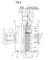
- Fig. 3 shows another example of the actualization for facilitating the vertical temperature difference creating action for the stored water W 1 in the water storage tank 1 by the in-tank heat exchanger 10.
- the heating and hot water supply apparatus shown in Fig. 3 is similar to the heating and hot water supply apparatus shown in Fig. 1 in that the water-supply side pipe line 7 running to the in-tank heat exchanger 10 is vertically provided in a straight pipe shape up to a vicinity of the bottom portion within the water storage tank 1 while the range from the lower end of the water-supply side pipe line 7 to the outlet-side pipe line 8 on the exit side is provided by the in-tank heat exchanger 10, which is a coiled tubular member.
- the in-tank heat exchanger 10 which is formed as a coiled tubular member, is made higher in coil density (larger in coil turns within an identical height) in its lower-side portion 10B than in its upper-side portion 10A, by which heat exchange action between the stored water W 1 in the water storage tank 1 and the flow-through water (water to be heated) W 2 flowing through within the in-tank heat exchanger 10 becomes greater in the lower-side portion 10B of the heat exchanger 10 than in its upper-side portion 10A.
- the endothermic (heat removal) action for the stored water W 1 in the water storage tank 1 is greater in the lower-side portion W 1b of the stored water W 1 than in its upper-side portion W 1a so that temperature decreasing action in the lower-side portion W 1b of the stored water W 1 in the water storage tank 1 becomes greater than in the upper-side portion W 1a by the most possible extent.
- a portion (a lowermost end side portion of the lower-side portion 10B) 10C of the in-tank heat exchanger 10 is formed into a spiral shape 10C of small vertical height differences.
- the spiral shape portion 10C serves as a resistive member against vertical flow of the stored water W 1 in the water storage tank 1 (uniformization of water temperatures in the water storage tank 1 is thereby suppressed).
- a baffle member for restricting the vertical water flow is provided in the water storage tank 1, by which the heating efficiency by the heat pump unit 2 can be further improved.
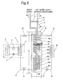
- the baffle member may be a transverse plate member 41A that vertically divides the internal space of the water storage tank 1 as illustrated in Figs. 1 and 3 , or a vertical plate member 41B that diametrally divides the internal space of the water storage tank 1 as illustrated in Fig. 4 , or a combination of the transverse plate member 41A and the vertical plate member 41B as illustrated in Fig. 5 .
- the transverse plate member 41A illustrated in Figs. 1 , 3 and 5 may be a disc-shaped porous plate (or nonporous plate) made of synthetic resin or stainless steel as an example. As to the number of the transverse plate member 41A, only one transverse plate member 41A may be provided at an intermediate height position higher than an opening 21a of the lower-position side water pipe 21 in the water storage tank 1, or a plurality of the transverse plate members 41A may be provided in a multistage fashion.
- the vertical plate member 41B illustrated in Figs. 4 and 5 may be a cylindrical-shaped porous plate (or nonporous plate) made of synthetic resin or stainless steel as an example. As to the number of the vertical plate member 41B, only one vertical plate member 41B may be provided at an intermediate height position higher than the opening 21a of the lower-position side water pipe 21 in the water storage tank 1, or a plurality of the vertical plate members 41B may be provided in a concentric form.
- Functioning of the vertical plate member 41B as a baffle member that restricts the vertical water flow in the water storage tank 1 is based on the condition that the vertical water flow (convection) in the water storage tank 1 is suppressed by the vertical plate member 41B diametrally subdividing the internal space of the water storage tank 1 more than when no vertical plate member 41B is provided.
- the lower-side portion 10B side of the in-tank heat exchanger 10 may be formed as an internally grooved tube having good heat exchange action, so that the heat exchange action in the lower-side portion 10B of the in-tank heat exchanger 10 is further facilitated.
- Each of the heating and hot water supply apparatuses illustrated in Figs. 1 , 3 , 4 and 5 includes: a heat pump unit 2 having a compressor 3 for compressing a refrigerant, a radiative heat exchanger 4 for condensing the compressed refrigerant to radiate heat, and an endothermic heat exchanger 6 for evaporating the condensed refrigerant and absorbing heat from the air; and a water storage tank 1 which is connected to the heat pump unit 2 via a lower-position side water pipe 21 and a higher-position side water pipe 22 and in which water W 1 to be heated by the radiative heat exchanger 4 is stored and moreover which is internally provided with a heat exchanger 10 for performing heat exchange with the stored water W 1 to heat flow-through water W 2 flowing through the interior the heat exchanger 10, so that hot water (W 2 ) heated by the in-tank heat exchanger 10 is made usable for direct supply to the human body as in baths, kitchens, shower baths and the like.
- the heating and hot water supply apparatus has an aspect ratio (H/D) of the water storage tank 1 set to 4.0 or more, the vertical water flow in the water storage tank 1 can be suppressed so that the lower-side portion W 1b of the stored water W 1 in the water storage tank 1 can be maintained at relatively low temperatures.
- H/D aspect ratio
- Each of the heating and hot water supply apparatuses includes: a heat pump unit 2 having a compressor 3 for compressing a refrigerant, a radiative heat exchanger 4 for condensing the compressed refrigerant to radiate heat, and an endothermic heat exchanger 6 for evaporating the condensed refrigerant and absorbing heat from the air; and a water storage tank 1 which is connected to the heat pump unit 2 via a lower-position side water pipe 21 and a higher-position side water pipe 22 and in which water W 1 to be heated by the radiative heat exchanger 4 is stored and moreover which is internally provided with a in-tank heat exchanger 10 for performing heat exchange with the stored water W 1 to heat flow-through water W 2 flowing through the interior of the in-tank heat exchanger 10.
- the aspect ratio H/D (height H to inner diameter D ratio in the water storage tank 1) of the water storage tank 1 is set to 4.0.
- a baffle member in various formations is provided as an additional means for suppressing the vertical water flow in the water storage tank 1.
- Figs. 1 and 3 shows embodiments in which a baffle member formed of a transverse plate member 41A is provided in the water storage tank 1.
- Fig. 4 shows an embodiment in which a baffle member formed of a cylindrical-shaped vertical plate member 41B is provided in the water storage tank 1.
- Fig. 5 shows an embodiment in which a baffle member formed of a transverse plate member 41A and up-and-down two baffle members formed of cylindrical-shaped vertical plate members 41B are provided in the water storage tank 1.
- the transverse plate member 41A is, in many cases, provided by a porous plate made of stainless steel or synthetic resin.
- the transverse plate member 41A does not necessarily need to be a porous plate only if it can suppress the vertical water flow in the water storage tank 1, and may be, for example, a nonporous disc having a diameter slightly smaller than the inner diameter of the water storage tank 1.
- the vertical plate member 41B also is, in many cases, provided by a cylindrical member made of stainless steel or synthetic resin.
- the vertical plate member 41B does not necessarily need to be a cylindrical member, and may be a vertical plate member only if it can diametrally subdivide the interior of the water storage tank 1 to suppress the vertical water flow in the water storage tank 1.
- the water storage tank 1 in the heating and hot water supply apparatuses of those embodiments has an inner diameter D of 350 mm, an inner height H of 1400 mm and a volume of 135L, and an aspect ratio (H/D) of the water storage tank 1 in the heating and hot water supply apparatuses of these embodiments is 4.0.
- the radiative heat exchanger 4 of the heat pump unit 2 is connected to the water storage tank 1 via the lower-position side water pipe 21 and the higher-position side water pipe 22.
- the heat pump unit 2 includes a compressor 3 for compressing a refrigerant (CO 2 ), a radiative heat exchanger 4 for condensing the compressed refrigerant to radiate heat (to heat the stored water W 1 in the water storage tank 1), an expansion mechanism 5 for decompressing the refrigerant condensed by the radiative heat exchanger 4, and an endothermic heat exchanger 6 for evaporating the decompressed refrigerant and absorbing heat from the air.
- a compressor 3 for compressing a refrigerant (CO 2 )
- a radiative heat exchanger 4 for condensing the compressed refrigerant to radiate heat (to heat the stored water W 1 in the water storage tank 1)
- an expansion mechanism 5 for decompressing the refrigerant condensed by the radiative heat exchanger 4
- an endothermic heat exchanger 6 for evaporating the decompressed refrigerant and absorbing heat from the air.
- the stored water W 1 in the water storage tank 1 is fed to the radiative heat exchanger 4 of the heat pump unit 2 by a pump 23, and becomes hot water of 85.0 °C and flows back into the water storage tank 1 as such.
- the stored water (hot water) W 1 in the water storage tank 1 heats the flow-through water W 2 flowing through the interior of the in-tank heat exchanger 10 provided in the water storage tank 1, while being fed by a pump 33 toward a heating-use radiator 30 connected by pipe lines 31, 32, thus being usable also as a heating-use heat source.
- the radiator 30 feeds hot water of 85.0 °C at a rate of 15.0 L/m, as an example, for fulfillment of indoor heating.
- the in-tank heat exchanger 10 is formed of a coiled tubular member continuing to the water-supply side pipe line 7 vertically provided up to a vicinity of the bottom portion within the water storage tank 1, the coiled tubular member continuing to an outlet-side pipe line 8 on an upper end side of the heat exchanger 10.
- Supply water W 0 flowing in from the water-supply side pipe line 7, while flowing through the in-tank heat exchanger 10, is heat-exchanged with the stored water W 1 in the water storage tank 1 to become hot water (heated water) W 2 of 85°C, thus being taken out through the outlet-side pipe line 8.
- thermo valve 11 The water-supply side pipe line 7 and the outlet-side pipe line 8 arse connected to each other via a bypass pipe 9 and a thermo valve 11, and supply hot water W 3 of 42.0°C is taken out through a hot water supply pipe 12 by action of the thermo valve 11.
- reference sign 40 in Figs. 1 , 3 , 4 and 5 denotes an electric heater serving as an auxiliary heat source.
- the portion (lower-side portion) 10B of the in-tank heat exchanger 10 formed of a coiled tubular member is made smaller in tubular inner diameter than the upper-side portion 10A, so that the flow-through water W 2 flows within the in-tank heat exchanger 10 at a higher flow velocity in the lower-side portion 10B than in the upper-side portion 10A.
- the heat exchange action (heat removal action) for the lower-side portion W 1b of the stored water W 1 in the water storage tank 1 becomes greater than that for the upper-side portion W 1a .
- the in-tank heat exchanger 10 in this embodiment is so arranged and configured that a lower end portion 10C of the lower-side portion 10B of the coiled tubular member is made larger in coil density (smaller in coil interval and formed into a spiral shape) than the upper-side portion 10A of the heat exchanger in the water tank.
- the endothermic action (heat removal action) from the lower-side portion W 1b of the stored water by the largeness of the coil density itself becomes greater in the lower end portion (spiral shape portion) 10C of the heat exchanger in the water tank, so that the temperature decreasing action for the lower-side portion W 1b of the stored water becomes greater.
- the spiral shape portion 10C acts to suppress the vertical water flow in the water storage tank 1 so that the lower-side portion W 1b of the stored water in the water storage tank 1 is maintained as low temperatures as possible.
- an internally grooved tube may be provided over a certain range from the lower end side of the lower-side portion 10B of the in-tank heat exchanger 10 formed of a coiled tubular member so as to enhance the heat exchange action (heat removal action) for the lower-side portion W 1b of the stored water in the vicinity of the above range portion.
- the stored water W 1 in the water storage tank 1 may be boiled up by the heat pump unit 2 so as to be hot water, and then fed to the heating-use radiator 30, so that heat of the resulting hot water can be supplied to the heating-use radiator 30 efficiently without passing through the heat exchanger.
- the heating and hot water supply apparatuses are enabled to fulfill enough heating in such regions of high heating loads as Nordic countries where 24-hour heating operation is involved in winter.
Landscapes
- Engineering & Computer Science (AREA)
- Physics & Mathematics (AREA)
- Thermal Sciences (AREA)
- Mechanical Engineering (AREA)
- General Engineering & Computer Science (AREA)
- Chemical & Material Sciences (AREA)
- Combustion & Propulsion (AREA)
- Heat-Pump Type And Storage Water Heaters (AREA)
- Steam Or Hot-Water Central Heating Systems (AREA)
- Details Of Fluid Heaters (AREA)
Applications Claiming Priority (3)
| Application Number | Priority Date | Filing Date | Title |
|---|---|---|---|
| JP2007091322 | 2007-03-30 | ||
| JP2008069840A JP2008275302A (ja) | 2007-03-30 | 2008-03-18 | 暖房給湯装置 |
| PCT/JP2008/055417 WO2008123188A1 (fr) | 2007-03-30 | 2008-03-24 | Installation d'alimentation en eau chaude pour le chauffage |
Publications (1)
| Publication Number | Publication Date |
|---|---|
| EP2154443A1 true EP2154443A1 (fr) | 2010-02-17 |
Family
ID=39830685
Family Applications (1)
| Application Number | Title | Priority Date | Filing Date |
|---|---|---|---|
| EP08738756A Withdrawn EP2154443A1 (fr) | 2007-03-30 | 2008-03-24 | Installation d'alimentation en eau chaude pour le chauffage |
Country Status (4)
| Country | Link |
|---|---|
| US (1) | US20100126705A1 (fr) |
| EP (1) | EP2154443A1 (fr) |
| JP (1) | JP2008275302A (fr) |
| WO (1) | WO2008123188A1 (fr) |
Cited By (3)
| Publication number | Priority date | Publication date | Assignee | Title |
|---|---|---|---|---|
| GB2525856A (en) * | 2014-05-05 | 2015-11-11 | Martin Hook | A thermal store and water storage cylinder designed to enhance the performance of a CO2 heat pump |
| WO2018229679A1 (fr) * | 2017-06-14 | 2018-12-20 | Innova S.R.L. | Appareil de conditionnement thermique |
| GR1010412B (el) * | 2022-07-13 | 2023-02-20 | Clima Control Ανωνυμη Εμπορικη Εταιρια Συστηματων Θερμανσης Και Κλιματισμου, | Συστημα αντλιας θερμοτητας με δοχειο διπλου εναλλακτη |
Families Citing this family (11)
| Publication number | Priority date | Publication date | Assignee | Title |
|---|---|---|---|---|
| US8720109B2 (en) * | 2011-01-25 | 2014-05-13 | Technologies Holdings Corp. | Portable heating system for pest control |
| JP5884042B2 (ja) * | 2011-05-31 | 2016-03-15 | パナソニックIpマネジメント株式会社 | ヒートポンプ式温水暖房装置 |
| ES2442247B1 (es) * | 2012-04-30 | 2014-09-02 | Jessica GUTIERREZ MURIANO | Equipo enfriador-recuperador para refrigeración de instalaciones |
| KR101379766B1 (ko) * | 2012-05-03 | 2014-04-01 | 주식회사 경동나비엔 | 난방효율을 향상시킨 난방 및 온수의 동시 사용이 가능한 보일러 |
| JP2014145532A (ja) * | 2013-01-29 | 2014-08-14 | Mitsubishi Electric Corp | 熱媒体利用装置 |
| PL2818821T3 (pl) * | 2013-06-27 | 2016-07-29 | Linde Ag | Nawijany wymiennik ciepła z zasilaniem rury rdzeniowej |
| US9746190B2 (en) * | 2014-06-06 | 2017-08-29 | Intellihot, Inc. | Combined heating system capable of bi-directional heating |
| WO2017027857A1 (fr) * | 2015-08-12 | 2017-02-16 | Sarkis Sr Anthony Michael | Système de chauffage à eau chaude et procédés associés |
| DE102017107394A1 (de) * | 2017-04-06 | 2018-10-11 | Stiebel Eltron Gmbh & Co. Kg | Wärmepumpenanlage |
| CN109654582B (zh) * | 2018-12-18 | 2023-10-10 | 北京中安金圣科技有限公司 | 一种储能供热设备 |
| KR102234392B1 (ko) * | 2019-11-19 | 2021-04-01 | 오문근 | 열교환 보일러 |
Family Cites Families (36)
| Publication number | Priority date | Publication date | Assignee | Title |
|---|---|---|---|---|
| US2020064A (en) * | 1933-10-13 | 1935-11-05 | Horace S Kehm | Heating system |
| US2060452A (en) * | 1934-01-19 | 1936-11-10 | Harrison D Sterick | Water heater |
| US2345209A (en) * | 1941-10-08 | 1944-03-28 | Robert E Moore | Heating system |
| US3545228A (en) * | 1968-12-04 | 1970-12-08 | Ice Ind Intern Inc | Limited subcooling condenser-receiver assembly for refrigerating systems |
| US4365483A (en) * | 1981-07-01 | 1982-12-28 | Binger Larry W | Vertical convection heat dissipation tower |
| JPS5881441U (ja) * | 1981-11-26 | 1983-06-02 | 塩見 市太郎 | タンク |
| US4474018A (en) * | 1982-05-06 | 1984-10-02 | Arthur D. Little, Inc. | Heat pump system for production of domestic hot water |
| EP0173173A3 (fr) * | 1984-08-29 | 1986-07-30 | Konvektco Nederland B.V. | Echangeur de chaleur |
| US4907738A (en) * | 1984-09-20 | 1990-03-13 | Conserve, Inc. | Heat pump |
| US5228505A (en) * | 1986-02-21 | 1993-07-20 | Aqua Systems Inc. | Shell and coil heat exchanger |
| US4959975A (en) * | 1987-05-14 | 1990-10-02 | Conserve, Inc. | Heat pump system |
| JPH07117290B2 (ja) * | 1987-12-18 | 1995-12-18 | ダイキン工業株式会社 | 給湯装置 |
| US4880505A (en) * | 1988-11-23 | 1989-11-14 | Lloyd Berg | Separation of M-diisopropylbenzene from P-diisopropylbenzene by azeotropic distillation with esters |
| US5052187A (en) * | 1989-07-21 | 1991-10-01 | Robinson Jr Glen P | Water flow control for heat pump water heaters |
| CA2121794A1 (fr) * | 1991-10-30 | 1993-05-13 | Theodore C. Gilles | Thermopompe auxiliaire destinee a produire de l'eau chaude pour usage domestique |
| US5372185A (en) * | 1993-06-29 | 1994-12-13 | Bradford-White Corporation | Combined water heater and heat exchanger |
| US5485879A (en) * | 1993-06-29 | 1996-01-23 | Bradford White Corporation | Combined water heater and heat exchanger |
| US5596952A (en) * | 1995-07-24 | 1997-01-28 | Bradford White Corporation | Indirect water heater |
| US5858252A (en) * | 1995-08-08 | 1999-01-12 | Darcy; Harold J. | Liquid purification system |
| TW445366B (en) * | 1998-05-15 | 2001-07-11 | Noboru Maruyama | Assembly body of heat exchange coils |
| JP4104261B2 (ja) * | 1999-11-30 | 2008-06-18 | 株式会社デンソー | 給湯装置 |
| JP3737381B2 (ja) * | 2000-06-05 | 2006-01-18 | 株式会社デンソー | 給湯装置 |
| JP2003130457A (ja) * | 2001-10-26 | 2003-05-08 | Sanyo Electric Co Ltd | 貯湯タンク及び貯湯システム |
| JP3742356B2 (ja) * | 2002-03-20 | 2006-02-01 | 株式会社日立製作所 | ヒートポンプ給湯機 |
| JP3741103B2 (ja) | 2003-01-29 | 2006-02-01 | 松下電器産業株式会社 | 給湯装置 |
| JP3900098B2 (ja) * | 2003-03-20 | 2007-04-04 | 株式会社デンソー | 給湯装置 |
| JP3918786B2 (ja) * | 2003-07-30 | 2007-05-23 | 株式会社デンソー | 貯湯式ヒートポンプ給湯装置 |
| US7007748B2 (en) * | 2003-09-30 | 2006-03-07 | Bradford White Corporation | Indirect water heater and method of manufacturing same |
| JP4501446B2 (ja) * | 2004-02-06 | 2010-07-14 | ダイキン工業株式会社 | 給湯用熱交換器 |
| US20050217839A1 (en) * | 2004-03-30 | 2005-10-06 | Papapanu Steven J | Integral primary and secondary heat exchanger |
| JP2006275357A (ja) * | 2005-03-29 | 2006-10-12 | Corona Corp | 給湯装置 |
| JP4736533B2 (ja) * | 2005-05-18 | 2011-07-27 | パナソニック株式会社 | 熱交換器 |
| JP3876911B2 (ja) * | 2005-06-29 | 2007-02-07 | ダイキン工業株式会社 | 給湯装置 |
| US7578933B1 (en) * | 2005-12-16 | 2009-08-25 | Benjamin B. Selman | Biological filter for aquatic ecosystems |
| JP2008267790A (ja) * | 2007-03-27 | 2008-11-06 | Daikin Ind Ltd | ヒートポンプ式給湯装置および暖房給湯装置 |
| JP4539777B2 (ja) * | 2008-02-01 | 2010-09-08 | ダイキン工業株式会社 | 貯湯式給湯機および貯湯式暖房給湯機 |
-
2008
- 2008-03-18 JP JP2008069840A patent/JP2008275302A/ja active Pending
- 2008-03-24 EP EP08738756A patent/EP2154443A1/fr not_active Withdrawn
- 2008-03-24 WO PCT/JP2008/055417 patent/WO2008123188A1/fr active Application Filing
- 2008-03-24 US US12/593,892 patent/US20100126705A1/en not_active Abandoned
Non-Patent Citations (1)
| Title |
|---|
| See references of WO2008123188A1 * |
Cited By (3)
| Publication number | Priority date | Publication date | Assignee | Title |
|---|---|---|---|---|
| GB2525856A (en) * | 2014-05-05 | 2015-11-11 | Martin Hook | A thermal store and water storage cylinder designed to enhance the performance of a CO2 heat pump |
| WO2018229679A1 (fr) * | 2017-06-14 | 2018-12-20 | Innova S.R.L. | Appareil de conditionnement thermique |
| GR1010412B (el) * | 2022-07-13 | 2023-02-20 | Clima Control Ανωνυμη Εμπορικη Εταιρια Συστηματων Θερμανσης Και Κλιματισμου, | Συστημα αντλιας θερμοτητας με δοχειο διπλου εναλλακτη |
Also Published As
| Publication number | Publication date |
|---|---|
| US20100126705A1 (en) | 2010-05-27 |
| WO2008123188A1 (fr) | 2008-10-16 |
| JP2008275302A (ja) | 2008-11-13 |
Similar Documents
| Publication | Publication Date | Title |
|---|---|---|
| EP2154443A1 (fr) | Installation d'alimentation en eau chaude pour le chauffage | |
| JP4787284B2 (ja) | ヒートポンプ式給湯装置 | |
| JP5077338B2 (ja) | 暖房給湯装置 | |
| US8978744B2 (en) | Hot-water storage type hot-water supply device and hot-water storage type heating and hot-water supply device | |
| EP2136151B1 (fr) | Installation de fourniture d'eau chaude de type pompe à chaleur et appareil de chauffage et fourniture d'eau chaude | |
| JP4298666B2 (ja) | ヒートポンプ給湯機 | |
| US20160313026A1 (en) | Heat Exchanger, Heating Device, Heating System and Method for Heating Water | |
| US20140003801A1 (en) | Water heating system | |
| JP5399327B2 (ja) | 貯湯タンクユニット | |
| JP2005291684A (ja) | 熱交換装置及びそれを用いたヒートポンプ給湯装置 | |
| JP2008241177A (ja) | ヒートポンプ式給湯装置 | |
| WO2021010168A1 (fr) | Unité réservoir de stockage | |
| WO2021010155A1 (fr) | Unité réservoir de stockage | |
| JP4383238B2 (ja) | 給湯装置 | |
| WO2000050821A1 (fr) | Chaudiere mixe | |
| JP4155162B2 (ja) | 貯湯式給湯装置 | |
| JP4161669B2 (ja) | 給湯装置 | |
| JP2015105804A (ja) | 加熱装置 | |
| WO2023144889A1 (fr) | Chauffe-eau à stockage | |
| JP2013242048A (ja) | 省エネ貯留方法及び貯湯式給湯機 | |
| JP4082343B2 (ja) | ヒートポンプ式給湯装置 | |
| JP2010169317A (ja) | ヒートポンプ給湯機 | |
| JP2006125837A (ja) | ヒートポンプ給湯機 | |
| JP2005315553A (ja) | 貯湯式給湯装置の熱交換器ユニット | |
| JP2008241170A (ja) | ヒートポンプ式給湯装置 |
Legal Events
| Date | Code | Title | Description |
|---|---|---|---|
| PUAI | Public reference made under article 153(3) epc to a published international application that has entered the european phase |
Free format text: ORIGINAL CODE: 0009012 |
|
| 17P | Request for examination filed |
Effective date: 20091008 |
|
| AK | Designated contracting states |
Kind code of ref document: A1 Designated state(s): AT BE BG CH CY CZ DE DK EE ES FI FR GB GR HR HU IE IS IT LI LT LU LV MC MT NL NO PL PT RO SE SI SK TR |
|
| AX | Request for extension of the european patent |
Extension state: AL BA MK RS |
|
| DAX | Request for extension of the european patent (deleted) | ||
| STAA | Information on the status of an ep patent application or granted ep patent |
Free format text: STATUS: THE APPLICATION HAS BEEN WITHDRAWN |
|
| 18W | Application withdrawn |
Effective date: 20131008 |